

Webinar: Simplifying touch sensing solutions for HMI applications October 2017
1

Introduction
Brian McCarthy Marketing Director
2
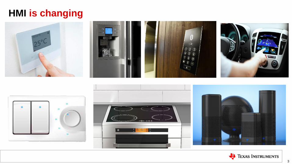
HMI is changing
3

Change enabler: Capacitive & inductive sensing
Capacitive touch Sleek industrial designs: with seamless glass, plastic or metal surfaces. Supporting HMI in different shapes and sizes Reliability: no moving parts make the design less prone to failure Harsh environment operation: Perfect for moisture sensitive or other dirty and environmental conditions
B E N E F I T S
Directional sensing without physically touching the surface
Relies on the electrical properties of the human body to detect a user’s touch on a surface
Proximity sensing Detects the presence of nearby objects without any physical contact through a change in an electrical field
Gesture recognition
Inductive sensing Uses any conductor to implement HMI functions including deflection-based / touch-on-metal buttons, knobs, dials, and simple switches
4

Solutions for your HMI challenges
5
Proximity Buttons Sliders Wheels/Dials Gesture
CapTIvate™ Technology

6
LDC FDC
Family MSP430FR25xx/FR26xx LDC10xx, LDC1101, LDC131x, LDC161x, LDC0851, LDC211x
FDC1004, FDC211x, FDC221x
#Channels 16 (self), 64(mutual) 1-4 2-4
Integrated MCU Yes No* No*
Power (Avg current) < 5uA Avg ~26uA Avg ~26uA Avg
Sensitivity for metal touch Medium High -
Proximity distance ≤ 15 cm - ≥ 15cm
Auto Qual (AEC-Q100) No Yes Yes
Temp range -40°C to 85°C -40°C to 125°C -40°C to 125°C
Focused applications
Electronic lock Building Security Keypad Appliances – Cooktops Smart Speakers Thermostat Metering - buttons Sensor transmitter Gestures/Sliders/Wheels
Mobile phones Wearables Speakers/Tablets/Power Tool Appliances/HMI- Buttons/Knob Metering- Tamper detection Automotive-Infotainment Buttons/Knob/Seatbelt
Proximity sensing Liquid Level Sensing Ice/Frost detection Collision avoidance Sliders
CapTIvate™ Technology
TI Capacitive and Inductive sensing guide

MSP430™ MCUs with CapTIvate Technology Dennis Lehman Sr. Systems Application Engineer
7

Designing for Capacitive Touch: Considerations
8
• Plastic is typical • Glass is elegant and works well too • Metal is an option for harsh environments • Other materials such as wood, ceramic and more
• Buttons or keypads • Slider for up/down control • Wheel for menu selection • Proximity for wake up
Sensors Overlay material
Environment
• If battery powered, low power is important • If line powered, EM disturbances are a concern
Power
• Indoor or outdoor application • Is moisture/water tolerance important • Application in wide range of temperatures or humidity • Robustness and reliability
• LEDs used to illuminate button • Haptics for touch feedback • Audible feedback
LED backlighting / illumination and touch feedback

High resolution sliders and wheels > 10 bits of resolution
Industry’s lowest power consumption < 0.9uA per button LOW POWER
HIGH RESOLUTION
Operates under harsh environments RELIABLE
Set-up your design in five minutes or less with CapTIvate Design Center EASE-OF-USE
VERSATILE
New possibilities with elegant designs: Diverse materials, buttons, slider and wheel configurations with advanced user outputs
Benefits: CapTIvate capacitive touch technology

Applications enabled by CapTIvate technology
10
Easy-to-use autonomous peripheral
Set-up design in less than five minutes
Tolerant to EM disturbances
Operates under harsh environments
Enables elegant designs
Industry’s highest resolution sliders and wheels
Industry’s lowest power cap touch sensors
Applications
Benefits Elevator Panels E-Locks Security panels Light switches
1 - 64 buttons
High resolution sliders Sense through
60mm thick glass Metal overlay
Small sensors Moisture tolerant
Capabilities Appliances Consumer

Applications in Home Automation
11
TI’s CapTIvate technology benefits: • 12 button keypad with wake-on proximity • <3uA Avg power Years of battery life • Moisture tolerance capability • Plastic/glass or metal overlay • FRAM for state/passcode retention • User output: Backlight/Haptics/Buzzer
Electronic Locks / Keypads
Featured Reference Designs • Capacitive touch through glass • eLock • Access panel with Bluetooth
Thermostat TI’s CapTIvate technology benefits: • Low power Use with energy stealing • Replace resistive with cap touch • Support for ITO (transparent sensors) • FRAM for user profile retention • User output: Backlight/Haptics/Buzzer
Featured Reference Designs & Collateral • Capacitive thermostat user
interface • ITO whitepaper

Applications in Building Automation
12
TI’s CapTIvate technology benefits: • <3uA Years of battery life • Use 3D gestures • Up to 64 buttons with mutual capacitance • Up to 10cm prox. sensing for back light • Gesture pad for more complex HMI
Security Panels Featured Reference Designs: • 64 buttons • Capacitive touch remote control
Light Switches
TI’s CapTIvate technology benefits: • Immune to power line noise • Design flexibility with plastic, glass, wood,
metal overlay • FRAM for user profile retention • User output: Backlight/Haptics/Buzzer
Featured Reference Designs: • Capacitive touch HMIs • Capacitive touch thermostat
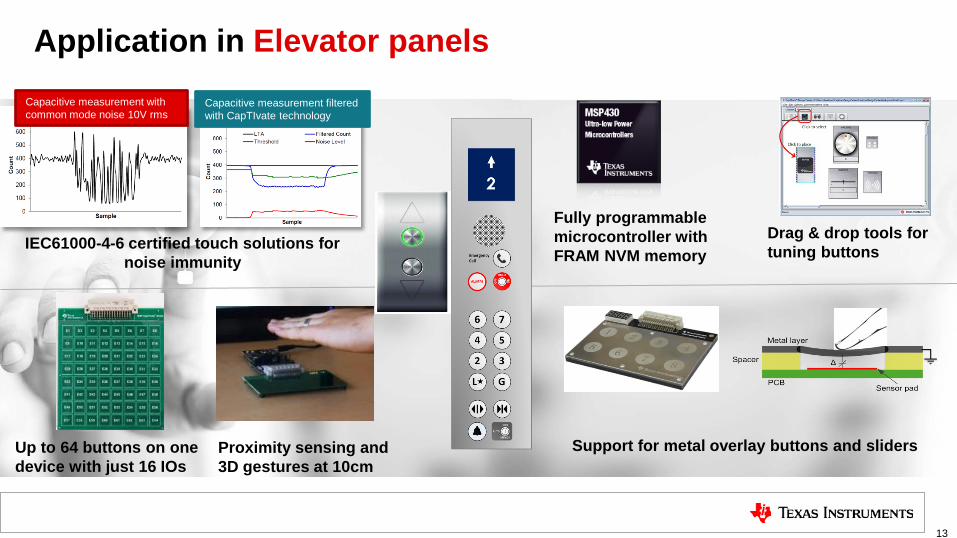
Application in Elevator panels
13
Capacitive measurement with common mode noise 10V rms
Capacitive measurement filtered with CapTIvate technology
IEC61000-4-6 certified touch solutions for noise immunity
Up to 64 buttons on one device with just 16 IOs
Proximity sensing and 3D gestures at 10cm
Support for metal overlay buttons and sliders
Fully programmable microcontroller with FRAM NVM memory
Drag & drop tools for tuning buttons

14
• Simplify and accelerate touch design with CapTIvate Design Center - one stop shop for tools, software and documentation
• Intuitive GUI tools for creating, configuring touch sensors and tuning them in real time • Tune buttons, sliders, wheels and proximity sensors for sensitivity, noise performance and
power consumption • Automated generation of complete source code projects for Code Composer Studio™ IDE and
IAR® IDEs
Ease-of-use Set-up your design in five minutes or less with CapTIvate Design Center
Drag & Drop Configure Real-time
tuning Generate Build

15
Proximity and gesture sensing is also possible with MSP430 MCUs with CapTIvate Technology
Most configurable button, slider and wheel combinations
Differentiate your solution with new materials
• Flexible combinations of buttons, sliders, wheels and prox. sensors in same design
• Design up to 64 buttons with just 16 IOs to simplify designs and reduce cost • Control user outputs: LEDs, Haptics, Buzzer
• Seamlessly integrate your sensors with metal, plastic, glass or wood panels • Increase functionality with multi-touch and force-touch
Versatility New possibilities with elegant designs
16 IOs = 32 buttons + 4 sliders + 4 wheels+ 1 prox
16
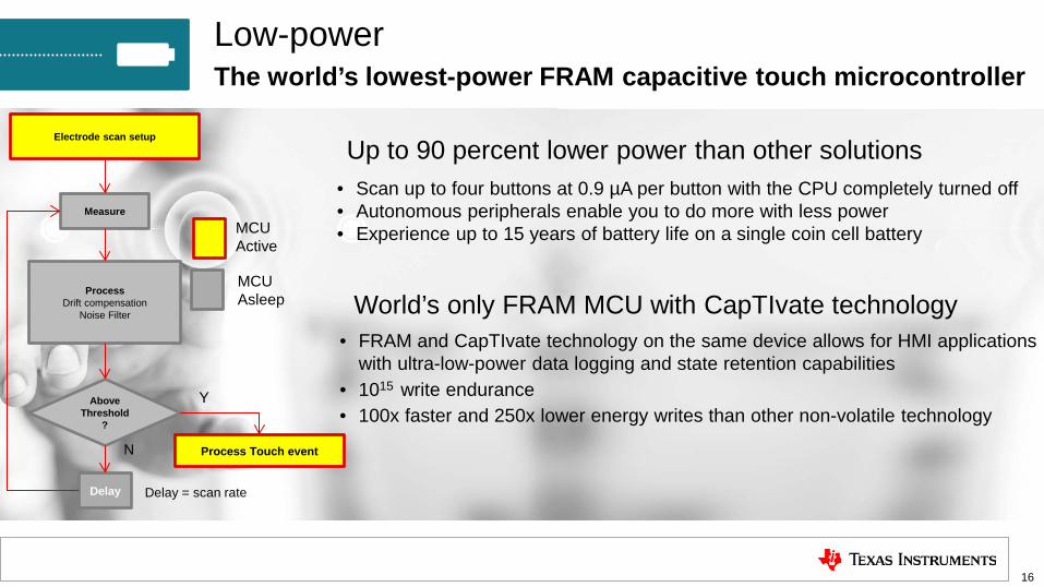
Up to 90 percent lower power than other solutions
World’s only FRAM MCU with CapTIvate technology
• Scan up to four buttons at 0.9 µA per button with the CPU completely turned off • Autonomous peripherals enable you to do more with less power • Experience up to 15 years of battery life on a single coin cell battery
• FRAM and CapTIvate technology on the same device allows for HMI applications with ultra-low-power data logging and state retention capabilities
• 1015 write endurance • 100x faster and 250x lower energy writes than other non-volatile technology
Low-power The world’s lowest-power FRAM capacitive touch microcontroller
MCU Active
Measure
Process Drift compensation
Noise Filter
Above Threshold
?
Delay
N
Electrode scan setup
Process Touch event
Y
Delay = scan rate
MCU Asleep
17
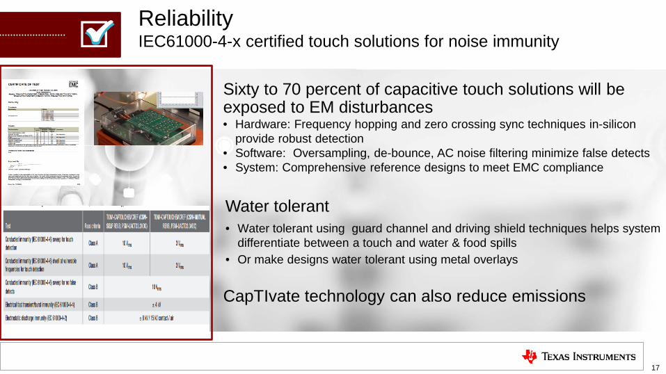
Sixty to 70 percent of capacitive touch solutions will be exposed to EM disturbances
Water tolerant
• Hardware: Frequency hopping and zero crossing sync techniques in-silicon provide robust detection
• Software: Oversampling, de-bounce, AC noise filtering minimize false detects • System: Comprehensive reference designs to meet EMC compliance
• Water tolerant using guard channel and driving shield techniques helps system differentiate between a touch and water & food spills
• Or make designs water tolerant using metal overlays
Reliability IEC61000-4-x certified touch solutions for noise immunity
CapTIvate technology can also reduce emissions
18
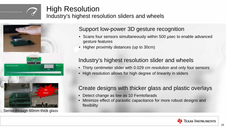
Create designs with thicker glass and plastic overlays
Industry’s highest resolution slider and wheels
Support low-power 3D gesture recognition
• Detect change as low as 10 Femtofarads • Minimize effect of parasitic capacitance for more robust designs and
flexibility
• Thirty centimeter slider with 0.029 cm resolution and only four sensors • High resolution allows for high degree of linearity in sliders
• Scans four sensors simultaneously within 500 µsec to enable advanced gesture features
• Higher proximity distances (up to 30cm)
High Resolution Industry’s highest resolution sliders and wheels
Sense through 60mm thick glass
60 mm!
Get started today
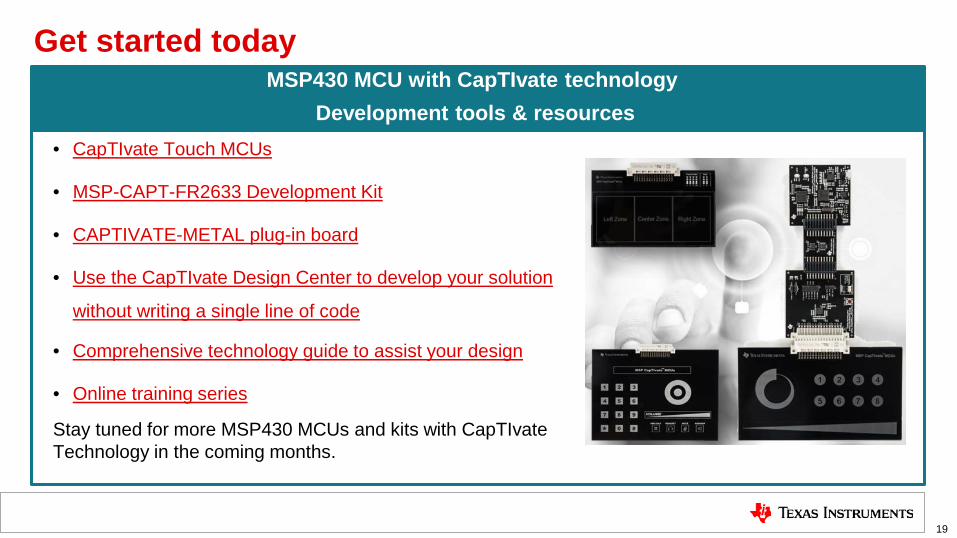
19
• CapTIvate Touch MCUs
• MSP-CAPT-FR2633 Development Kit
• CAPTIVATE-METAL plug-in board
• Use the CapTIvate Design Center to develop your solution
without writing a single line of code
• Comprehensive technology guide to assist your design
• Online training series
Stay tuned for more MSP430 MCUs and kits with CapTIvate Technology in the coming months.
MSP430 MCU with CapTIvate technology Development tools & resources

Inductive and capacitive sensing overview and applications
20
Chris Oberhauser Applications Engineer

Inductive sensing (LDC) – Fundamentals In
duct
ive
sens
ing
Ope
ratio
n PCB sensor coil
Conductive target
Flex sensor coil
Conductive target

Advantages of inductive sensing: • Does not require magnets • Reliable by virtue of being contactless • Insensitive to environmental contaminants (dust, dirt, etc.)
• Sub-micron resolution • Low-cost Sensor • LDC can be located remotely from the sensor
• Insensitive to DC magnetic fields • Works with wide range of conductors (steel, aluminum, copper, etc.…)
• Senses through non-conductors (plastic, glass, etc.…)
Sensing configuration Benefits
22
Inductive sensing Use cases enabled by inductive sensing

Inductive sensing (LDC) – Use cases Linear/lateral sensing Event counting Rotational sensing
Inductive touch
Inductive switches
Broad market LDC
Axial sensing (buttons)

Theory of operation
Inductive sensing (LDC) – HMI button
A flat metal plate held at a fixed distance from an inductive coil sensor. If a force is applied onto the metal plate, the metal will deform slightly.
As the conductive target moves closer to the sensor, the magnetic field will induce circulating eddy currents and generate their own magnetic field. The electromagnetic coupling between them becomes stronger. As a result, the change in sensor frequency is also more significant.
distance = 500µm from the coil
Sensor coil on PCB New distance = ~495µm Deflection = ~5µm
Metal strip mounted on PCB: “button”

Button construction
• The sensor is firmly attached to the inside surface to avoid false touch detections
Inductive sensing (LDC) – HMI buttons Frequency change vs. deflection
• LDC2112/LDC2114 measures the
shift in frequency of an LC resonator sensor

Inductive sensing (LDC) – Use cases Linear/lateral sensing Event counting Rotational sensing
Inductive touch
Inductive switches
Broad market LDC
Axial sensing (buttons)

Inductive sensing (LDC) – HMI incremental knob
27

Inductive sensing (LDC) – Use cases Linear/lateral sensing Event counting Rotational sensing
Inductive touch
Inductive switches
Broad market LDC
Axial sensing (Buttons)
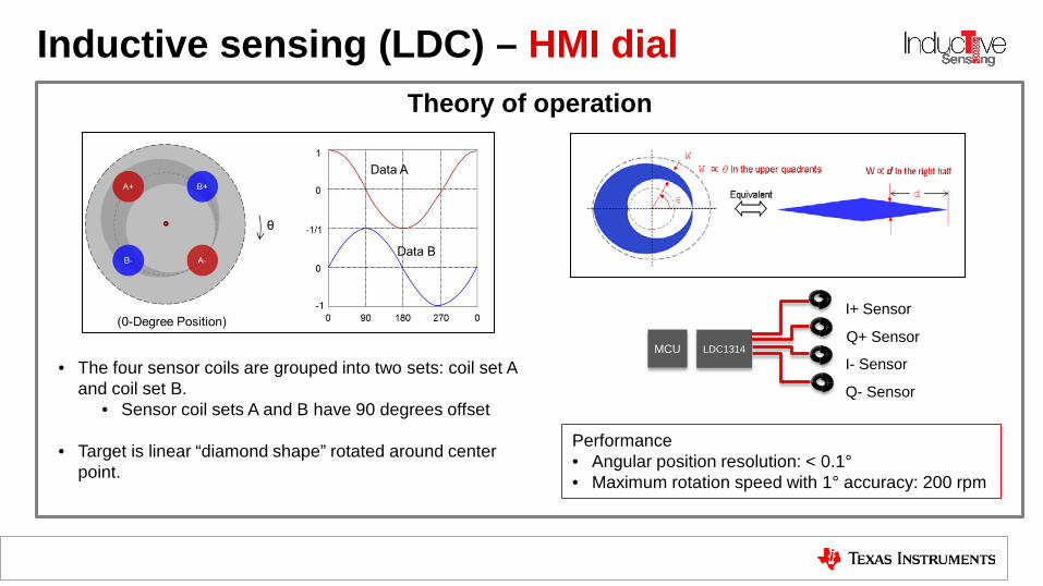
Inductive sensing (LDC) – HMI dial Theory of operation
• The four sensor coils are grouped into two sets: coil set A and coil set B.
• Sensor coil sets A and B have 90 degrees offset
• Target is linear “diamond shape” rotated around center point.
LDC1314
I+ Sensor
Q+ Sensor
I- Sensor
Q- Sensor
MCU
Performance • Angular position resolution: < 0.1° • Maximum rotation speed with 1° accuracy: 200 rpm
Inductive touch Inductive switches
Broad market LDC
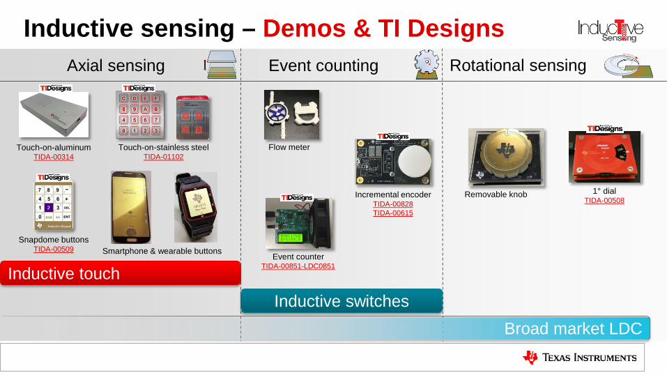
Inductive sensing – Demos & TI Designs
Removable knob
Flow meter
1° dial TIDA-00508
Event counter TIDA-00851-LDC0851
Touch-on-aluminum TIDA-00314
Snapdome buttons TIDA-00509
Touch-on-stainless steel TIDA-01102
Smartphone & wearable buttons
Incremental encoder TIDA-00828 TIDA-00615
Event counting Rotational sensing Axial sensing
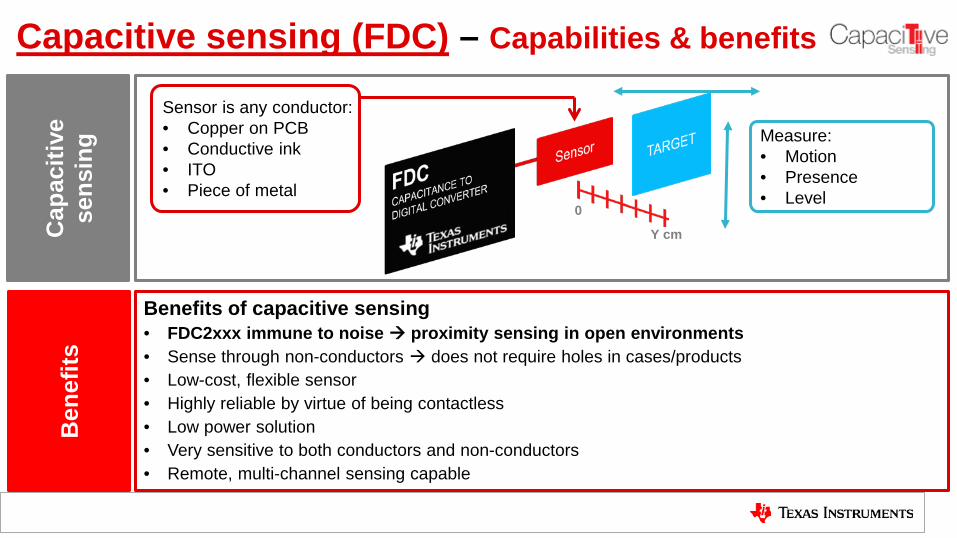
Benefits of capacitive sensing • FDC2xxx immune to noise proximity sensing in open environments • Sense through non-conductors does not require holes in cases/products • Low-cost, flexible sensor • Highly reliable by virtue of being contactless • Low power solution • Very sensitive to both conductors and non-conductors • Remote, multi-channel sensing capable
Cap
aciti
ve
sens
ing
Ben
efits
0
Y cm
Sensor is any conductor: • Copper on PCB • Conductive ink • ITO • Piece of metal
Measure: • Motion • Presence • Level
Capacitive sensing (FDC) – Capabilities & benefits

Charge-based measurement • Wideband input/antenna • Noise aliased in-band after sampling
Highly susceptible to noise
Oscillation-based measurement • High-Q narrowband band-pass filter • Strong noise rejection
Highly immune to noise
Example: Switched-cap
CIN
CIN
Example: Time-based /
Discharge
Frequency-to-digital converter
CIN
LFIXED
Switched-cap (SC) architecture Resonant sensing (FDC2xxx)
Capacitive sensing (FDC) – FDC2214 family

Capacitive sensing – Signal-to-noise comparison
# of samples
Mea
sure
d ca
paci
tanc
e of
FD
C22
14 (p
F)
Measured capacitance of traditional solutions (pF)
Each peak represents the response from a hand coming within 5 cm of a circular sensor that is 0.8 inch in diameter
Traditional cap-switch solution FDC2214
33

34
Capacitance measurements
Stage 1: No frost/ice • Constant capacitance value
Stage 2: Frost/ice gradually accumulates • Capacitance increases based on
thickness of ice due to dielectric change from air to ice
Stage 3: Frost/ice defrosting to water • Capacitance experiences a sharp
change due to the dielectric change from ice to water and returns to original value
Capacitive sensing (FDC) – Ice & frost detection
Applications • Refrigerators • Air conditioners • Freezers
TIDA-01465

35
Application use cases Measure level of liquid
in a container
ΔC/t
Liquid draining/filling rate
Liqu
id
Pressure, weight, force
Pressure, weight, force, … equivalency
System variables / parameters • Container material
• Conductor or non-conductor • Sensor location
• On container, remote, in liquid
• Environment • Nearby objects, temperature, etc.
• Liquid conductivity • Liquid viscosity
Liquid
FDC INxA INxB
Liquid
FDC INxA INxB
Liquid drains
Capacitive sensing (FDC) – Liquid level overview
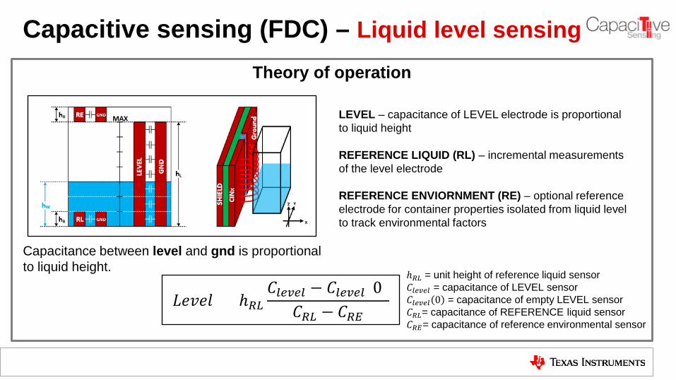
Theory of operation
Capacitive sensing (FDC) – Liquid level sensing
LEVEL – capacitance of LEVEL electrode is proportional to liquid height REFERENCE LIQUID (RL) – incremental measurements of the level electrode REFERENCE ENVIORNMENT (RE) – optional reference electrode for container properties isolated from liquid level to track environmental factors
Capacitance between level and gnd is proportional to liquid height.
𝐿𝐿𝐿𝐿𝐿 = ℎ𝑅𝑅𝐶𝑙𝑙𝑙𝑙𝑙 − 𝐶𝑙𝑙𝑙𝑙𝑙(0)
𝐶𝑅𝑅 − 𝐶𝑅𝑅
ℎ𝑅𝑅 = unit height of reference liquid sensor 𝐶𝑙𝑙𝑙𝑙𝑙 = capacitance of LEVEL sensor 𝐶𝑙𝑙𝑙𝑙𝑙 0 = capacitance of empty LEVEL sensor 𝐶𝑅𝑅= capacitance of REFERENCE liquid sensor 𝐶𝑅𝑅= capacitance of reference environmental sensor

Capacitive sensing – Demos & TI Designs Level sensing Proximity sensing Ice frost detection
TIDA-01465 (FDC2214)
TIDA-00317 (FDC1004) TIDA-01409
(FDC2212)
Proximity sensing
TIDA-00220 (FDC1004)
TIDA-01364/TIDA-00754 (FDC2214)
TIDA-00474 (FDC2214)
TIDA-00466 (FDC2214)
TIDA-00506 (FDC1004)

Thank you!
38


