
Year 2006 Report
“Better” Managed and Controlled Transmission Grids
usingAdvanced Technological Concepts
Aty Edris
EPRI
Power Delivery & Markets
2© 2007 Electric Power Research Institute, Inc. All rights reserved.
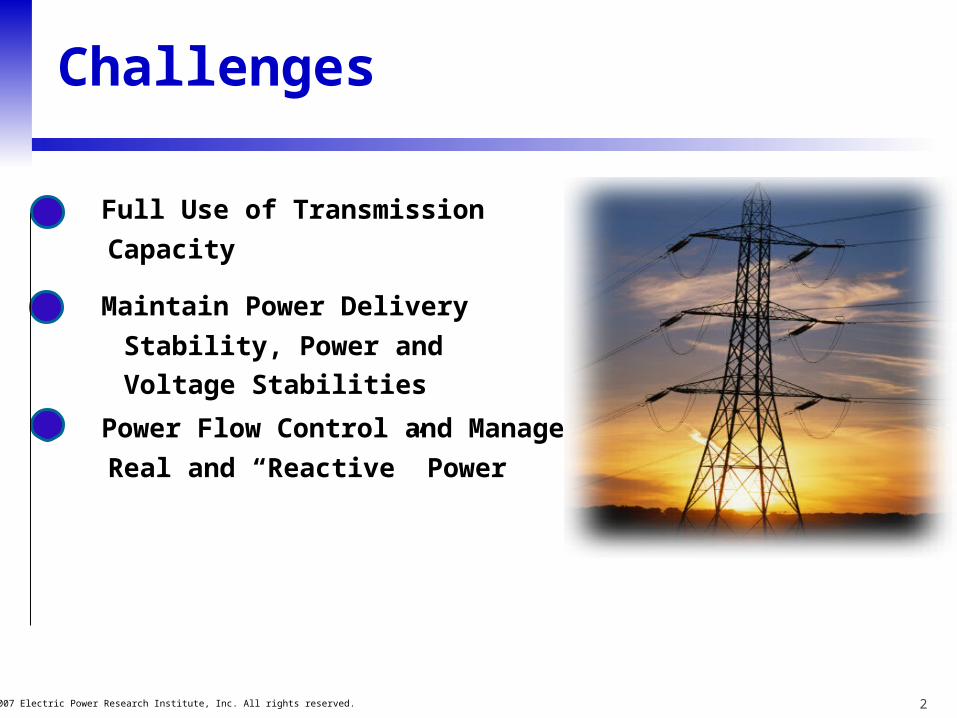
Challenges
• Full Use of Transmission
Capacity
• Maintain Power Delivery
Stability, Power and
Voltage Stabilities
• Power Flow Control and Management,
Real and “Reactive” Power

3© 2007 Electric Power Research Institute, Inc. All rights reserved.
R&D Work in 2006
• Reactive Power Management
• Operator/planner training simulator for the use of advanced technological Concepts
• Grid Shock Absorber Concept
• Bidirectional HVDC Valve and Tripole HVDC
• ETO-Based STATCOM for Wind Farm
• FACTS Technology- Information and Knowledge Sharing
4© 2007 Electric Power Research Institute, Inc. All rights reserved.
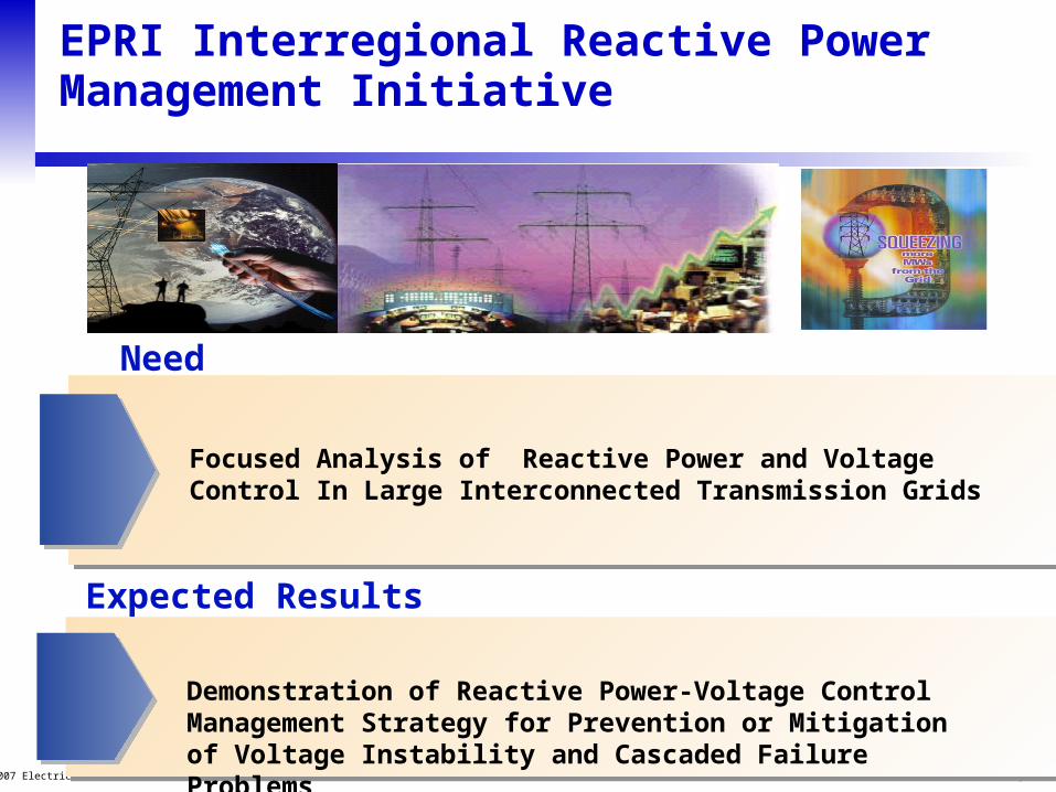
Need
Expected Results
EPRI Interregional Reactive Power Management Initiative
Focused Analysis of Reactive Power and Voltage Control In Large Interconnected Transmission Grids
Demonstration of Reactive Power-Voltage Control Management Strategy for Prevention or Mitigation of Voltage Instability and Cascaded Failure Problems

5© 2007 Electric Power Research Institute, Inc. All rights reserved.
Interrgional Reactive Power Management
EPRIs Interregional Reactive Power Management project aims at developing better methods for efficient use of reactive power resources and voltage control in order to improve power system operation reliability, security, and the functioning of markets.Reactive power planning is a key component. New methods are needed to help planners design systems which remain strong and robust under all conditions and contingencies.
2006 Results
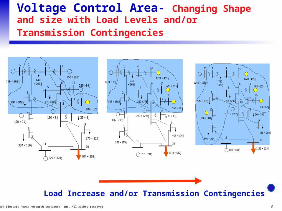
Development of highly automated method which identify “critical voltage control areas” in a system (for wide ranging topology, conditions, transfers and contingencies) and the required reactive power reserve solutions which will ensure system security.
6© 2007 Electric Power Research Institute, Inc. All rights reserved.
Voltage Control Area- Changing Shape and size
with Load Levels and/or Transmission Contingencies
750 +282j
250 +84j
100 +62j
20 + 8j
276 + 120j
130 + 8j
300 + 100j
750 + 262j 440+ 200j
120 + 11j
350 + 150j
227 + 420j 704 + 308j
2
3
4
5
7
6
1
8
9
1011
12 13
14
15
1617
176 +88j
1224 + 465j
408 + 155j
163 + 62jj
33 + 13j
458 + 199j
212 + 1297j
488 + 166j
1224 178j 731 + 365j
196 + 296j
531 + 219j
552 + 734j 1170 + 512j
2
3
4
5
7
6
1
8
9
1011
12 13
14
15
1617
282 +178j
1249 +465j
408 +155j
196 +62j
36 + 14j
488 + 203j
216 + 1597j
509 + 199j
1249 + 1550j 747+ 375j
200 + 300j
594 + 254j
602 + 813j 1195 + 523j
2
3
4
5
7
6
1
8
9
1011
12 13
14
15
1617
298 +149j
Load Increase and/or Transmission Contingencies
7© 2007 Electric Power Research Institute, Inc. All rights reserved.
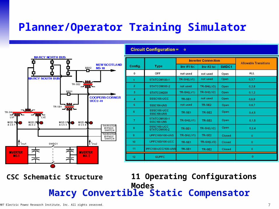
11 Operating Configurations ModesCSC Schematic Structure
Marcy Convertible Static Compensator
Planner/Operator Training Simulator
8© 2007 Electric Power Research Institute, Inc. All rights reserved.
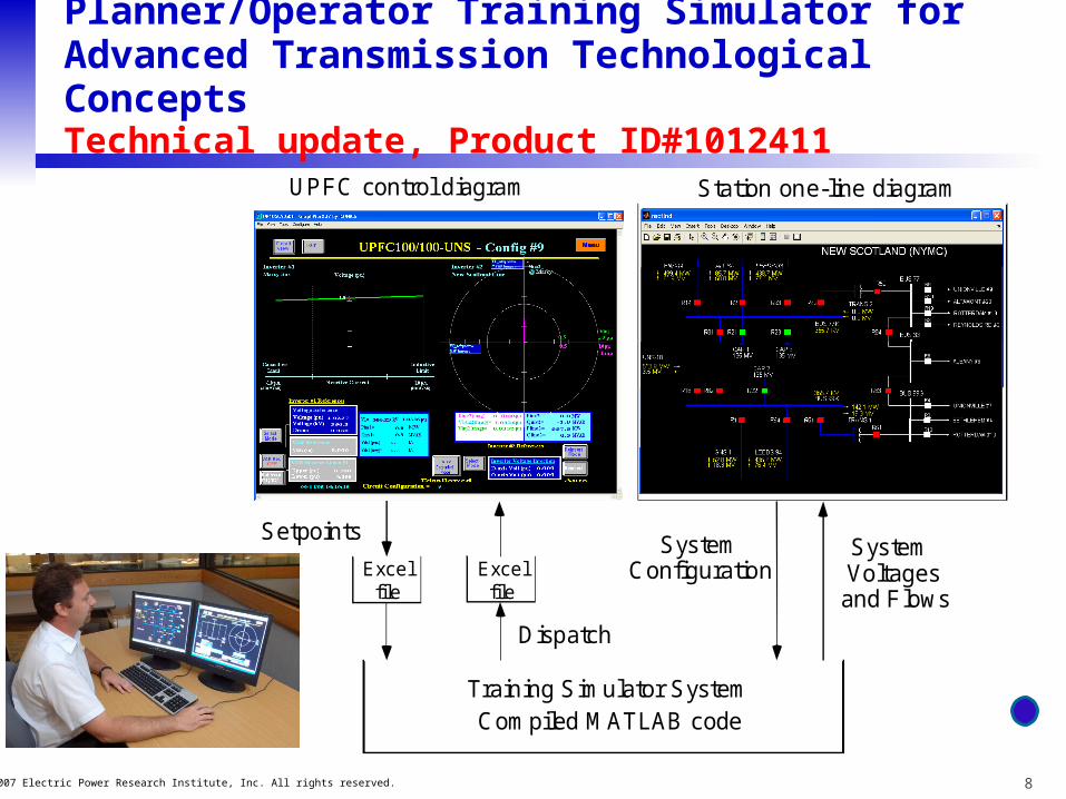
Planner/Operator Training Simulator for Advanced Transmission Technological ConceptsTechnical update, Product ID#1012411
Training Simulator SystemCompiled MATLAB code
Dispatch
SystemConfiguration
SetpointsSystemVoltagesand Flows
UPFC control diagram Station one-line diagram
Excelfile
Excelfile

9© 2007 Electric Power Research Institute, Inc. All rights reserved.
“Grid Shock Absorber” Implementation On Eastern Interconnection (EI)
VV
M W
Implementation of EPRI Converter-Based BTB Technology
Voltage supported junctionsSwitchingconverter
gcV V Vga gb
CouplingTransformer
Q
AT AC TERMINAL 2
DC terminal
Generator 1ac terminal
Vg
Parametersetting
Switchingconverter
gcV V Vga gb
Idc
CouplingTransformer
2V
DC terminal
Generator 2ac terminal
Vg
References
System variables
1V
Control P
2
2
>P2>Q2
P2 >Q2 <
00
00
>0P20Q2
<
0P20Q2
<<
Q
AT AC TERMINAL 1
P
1
1
>P1>Q1
P1 >Q1 <
00
00
>0P10Q1
<
0P10Q1
<<
C
Vdc
C
Vdc
+ +
P1 = -P2
MVA limitMVA limit
The idea !
Area 2Area 1
Grid Shock AbsorberSM

10© 2007 Electric Power Research Institute, Inc. All rights reserved.
“Grid Shock Absorber” Implementation On Eastern Interconnection (EI)
E
Ontario
D
Hydro Quebec
A
New England
B
New York
C
Outside World
PJM
B
A
D
C

11© 2007 Electric Power Research Institute, Inc. All rights reserved.
Impact of Generation Trip on Power Flows
G
B
A
D
C
1200 MW1625 MW
1150 MW
2775 MW
G150 MW G150 MW
500 MW500 MW
500 MW500 MW
G50 MW
G50 MW
G
50 MW
G
50 MW
G GG G
450 MW450 MW
Case 1 Case 1 –– With ac linksWith ac links
G
B
A
D
C
1200 MW1625 MW
2225 MW
G600 MW
G600 MW
600 MW
100 MW100 MW
100 MW100 MW
G400 MW G400 MW
Case 1 Case 1 –– With With dcdclinkslinks
B
Case 1 Case 1 –– With ac linksWith ac links Case 1 Case 1 –– With With dcdclinkslinks
12© 2007 Electric Power Research Institute, Inc. All rights reserved.
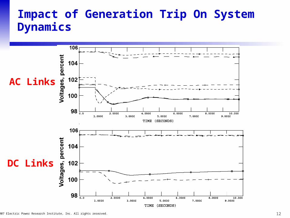
Impact of Generation Trip On System Dynamics
AC Links
DC Links

13© 2007 Electric Power Research Institute, Inc. All rights reserved.
Impact of “Larger” Generation Trip on Power Flows
G
B
A
D
C
2700 MW
1625 MW1625 MW
G100 MW
G100 MW100 MW
2600 MW2600 MW
Case 2 Case 2 –– With ac linksWith ac links
G
B
A
D
C
2700 MW1625 MW
2775 MW
G1550 MW
G1550 MW
1150 MW
150 MW
150 MW
G850 MW G850 MW
Case 2 Case 2 –– With With dcdclinkslinks
Selected bus voltages with ac ties (a) and dc links (b) in place. Voltages are not from the same buses in the two cases.
0.0 1.5 3.0 4.5 6.0 7.5 9.0 10.5 12.0 13.5 15.0
110
105
100
95
90
85
80
75
Volta
ges
(%)
Time (s)
Volta
ges
(%)
Time (s)
Volta
ges
(%)
Time (s)0.0 1.5 3.0 4.5 6.0 7.5 9.0 10.5 12.0 13.5 15.0
110
105
100
95
90
85
80
75
(a)
(b)
Technical Assessment of Grid Shock Absorber Proof of ConceptProduct ID # 1014494

14© 2007 Electric Power Research Institute, Inc. All rights reserved.
Bidirectional HVDC Valve and Tripole Concepts
Objectives • Enabling power reverse on a DC
transmission, without reversing Voltage Polarities at the transmission ends
• Tapping of existing HVDC lines• AC to DC line conversion• Providing a means for more reliable,
less costly applications of Cross Link Polyethylene (XLPE) cable for submarine & underground
Pole 3
Pole 1
Pole 2
A B
_
+
+/_

15© 2007 Electric Power Research Institute, Inc. All rights reserved.
Conversion of an AC Line into a Tripole DC Line
Pole 1
Pole 2
Pole 3
+
+
i 1
i 2
i 3
i ground = 0
-
• Higher $$/MW cost. Usually offset by increased transmission capacity
• About 40% more capacity compared to a bipole using the same 3-conductor system
• High redundancy: Loss of a converter or pole position drops just 16% of power at peak load
16© 2007 Electric Power Research Institute, Inc. All rights reserved.
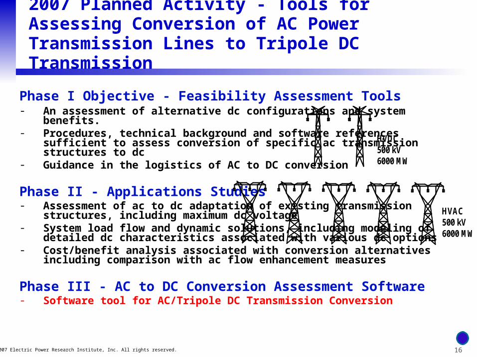
2007 Planned Activity - Tools for Assessing Conversion of AC Power Transmission Lines to Tripole DC Transmission
Phase I Objective - Feasibility Assessment Tools- An assessment of alternative dc configurations and system benefits.- Procedures, technical background and software references sufficient to
assess conversion of specific ac transmission structures to dc- Guidance in the logistics of AC to DC conversion
Phase II - Applications Studies - Assessment of ac to dc adaptation of existing transmission structures,
including maximum dc voltage- System load flow and dynamic solutions, including modeling of detailed dc
characteristics associated with various dc options - Cost/benefit analysis associated with conversion alternatives including
comparison with ac flow enhancement measures
Phase III - AC to DC Conversion Assessment Software - Software tool for AC/Tripole DC Transmission Conversion
HVDC500 kV 6000 MW
HVAC500 kV6000 MW

17© 2007 Electric Power Research Institute, Inc. All rights reserved.
Challenges (Cost of Converter-based Transmission Controllers!)
Converter-Based
Thyristor-Based
$ $ $ $$ $ $ $ $
Higher CostBetter PerformanceVersatile Functionality
Lower CostLimited PerformanceSingle Functionality
Cost Breakdown
(25%)
2050
18© 2007 Electric Power Research Institute, Inc. All rights reserved.
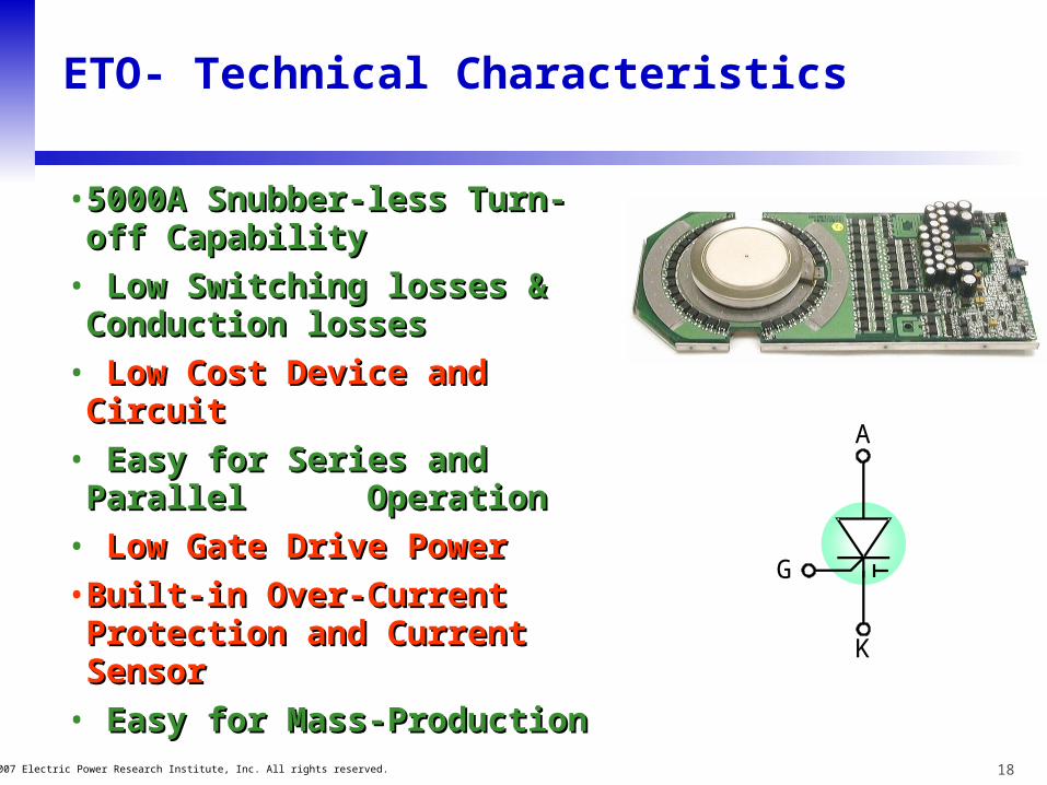
ETO- Technical Characteristics
• 5000A Snubber-less Turn-off 5000A Snubber-less Turn-off CapabilityCapability
• Low Switching losses & Low Switching losses & Conduction lossesConduction losses
• Low Cost Device and CircuitLow Cost Device and Circuit
• Easy for Series and Parallel Easy for Series and Parallel Operation Operation
• Low Gate Drive PowerLow Gate Drive Power
• Built-in Over-Current Built-in Over-Current Protection and Current SensorProtection and Current Sensor
• Easy for Mass-ProductionEasy for Mass-Production
G
A
K

19© 2007 Electric Power Research Institute, Inc. All rights reserved.
Field Demonstration of ETO-Based STATCOM
• 5-10 MVA ETO-Based STATCOM for Condon Windfarm
– Currently funded by BPA, TVA and TriState G&T
Current Objectives • Field demonstration of ETO-
based STATCOM, technically and economically, in mitigating voltage fluctuation due to a wind-driven induction generator
Big Eddy 115 kV
Klondike (wind)
De Moss 69 kV
Klondike (wind)
Rose bush (customer)
Condon Wind
Condon (customer)
Gordon Hollow (customer)
34 mi.
STATCOM
18 mi.
Fossil 69 kV
Maupin 115 kV
Maupin 69 kV
Bakeoven(customer)
Muddy Ranch(customer)
Antelope(customer)
24mi.
15 mi. 21 mi. 7 mi.
BPA Network-
Proposed Condon WindSTATCOM Project
70.4
70.6
70.8
71.0
71.2
71.4
71.6
71.8
72.0
72.2
72.4
72.6
72.8
5-M
ay-2
005
00:0
0
5-M
ay-2
005
06:0
0
5-M
ay-2
005
12:0
0
5-M
ay-2
005
18:0
0
6-M
ay-2
005
00:0
0
6-M
ay-2
005
06:0
0
6-M
ay-2
005
12:0
0
6-M
ay-2
005
18:0
0
7-M
ay-2
005
00:0
0
7-M
ay-2
005
06:0
0
7-M
ay-2
005
12:0
0
7-M
ay-2
005
18:0
0
8-M
ay-2
005
00:0
0
KV
69KV (69 kV) @CONDWIND: KV (62290), Date 5/5/2005-5/7/2005
Time

20© 2007 Electric Power Research Institute, Inc. All rights reserved.
FACTS Technology- Information and Knowledge Sharing
• Annual meeting, 9th FACTS Users Group meeting
• Reference Book, EPRI Power Electronics-Based Transmission Controllers Reference Book (“The Gold Book”)
• EPRIFACTS.Com
21© 2007 Electric Power Research Institute, Inc. All rights reserved.
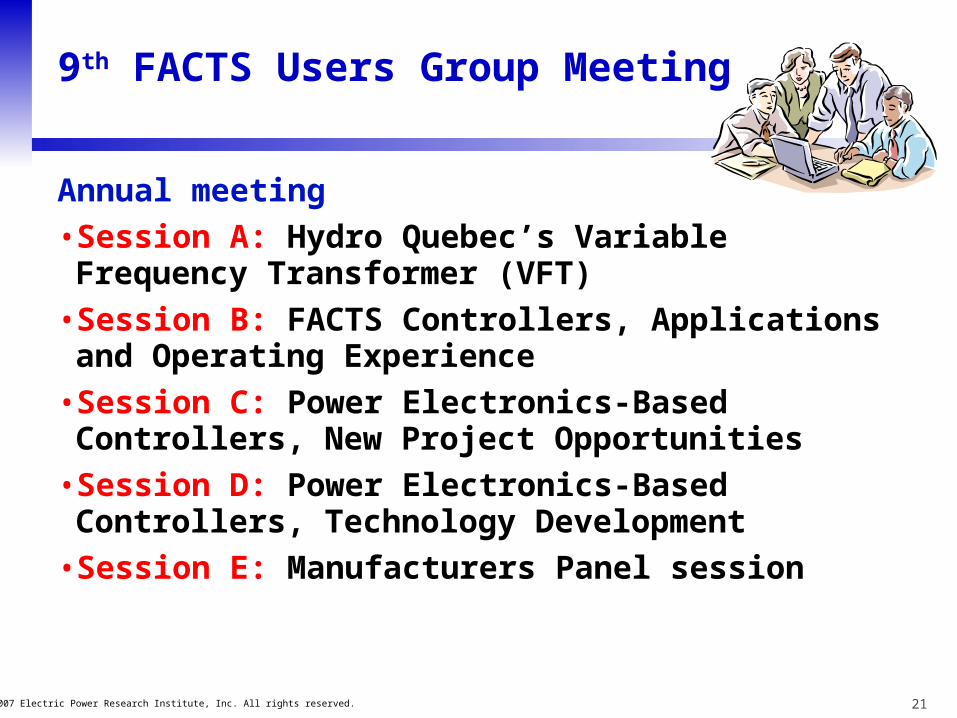
9th FACTS Users Group Meeting
Annual meeting
• Session A: Hydro Quebec’s Variable Frequency Transformer (VFT)
• Session B: FACTS Controllers, Applications and Operating Experience
• Session C: Power Electronics-Based Controllers, New Project Opportunities
• Session D: Power Electronics-Based Controllers, Technology Development
• Session E: Manufacturers Panel session
22© 2007 Electric Power Research Institute, Inc. All rights reserved.
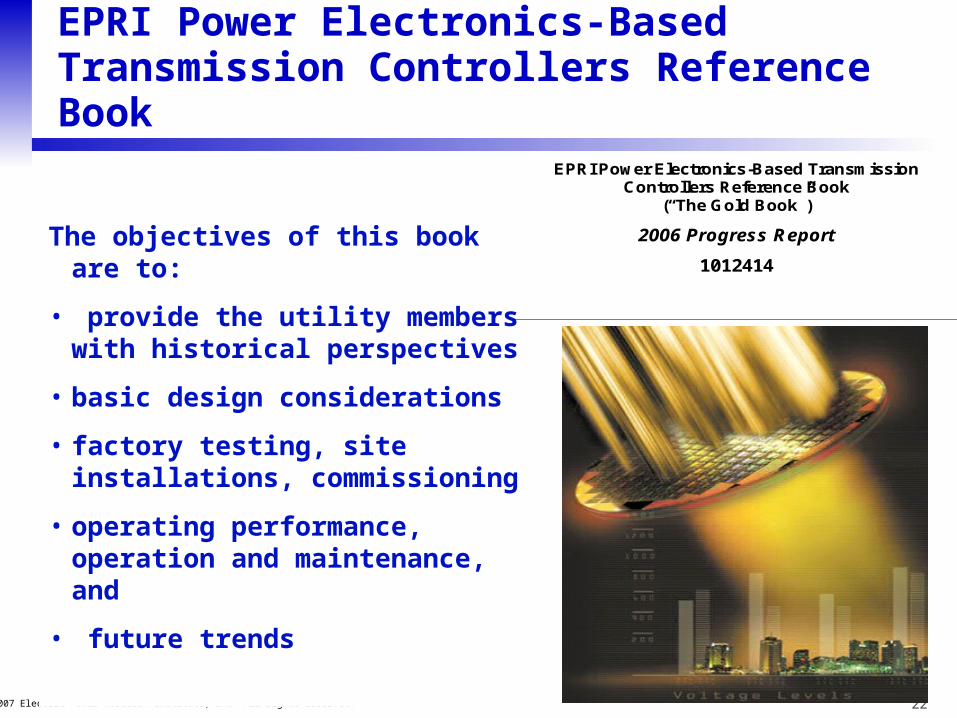
EPRI Power Electronics-Based Transmission Controllers Reference Book
The objectives of this book are to:
• provide the utility members with historical perspectives
• basic design considerations
• factory testing, site installations, commissioning
• operating performance, operation and maintenance, and
• future trends
EPRI Power Electronics-Based Transmission Controllers Reference Book
(“The Gold Book”)
2006 Progress Report
1012414

23© 2007 Electric Power Research Institute, Inc. All rights reserved.
EPRI Power Electronics-Based Transmission Controllers Reference Book
Written Chapters (five)• Alternating Current (AC)
Transmission Systems
• Power Semiconductors and Valves
• Generalized AC Transmission Controllers:
Unified Power Flow Controller and Interline Power Flow Controller
• Voltage Sourced Converter-Based DC Transmission
• AC to Tripole DC Transmission Conversion
Ten more Chapters to be written
EPRI Power Electronics-Based Transmission Controllers Reference Book
(“The Gold Book”)
2006 Progress Report
1012414
24© 2007 Electric Power Research Institute, Inc. All rights reserved.
THANKS FOR YOUR ATTENTION
Questions?
Together…..Shaping the Future of Electricity


