
8/12/2019 Zmep Kat Ne213 e
http://slidepdf.com/reader/full/zmep-kat-ne213-e 1/6
8/12/2019 Zmep Kat Ne213 e
http://slidepdf.com/reader/full/zmep-kat-ne213-e 2/6
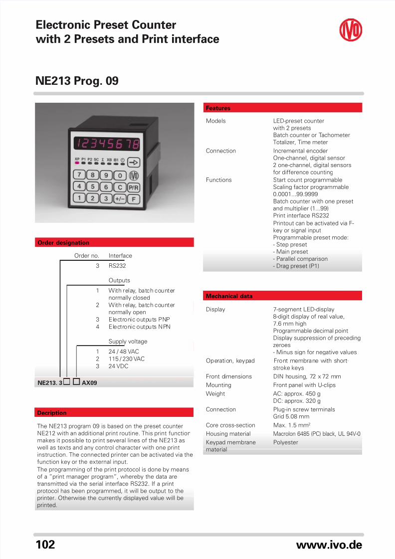
NE213 Prog. 09
103www.ivo.de
3
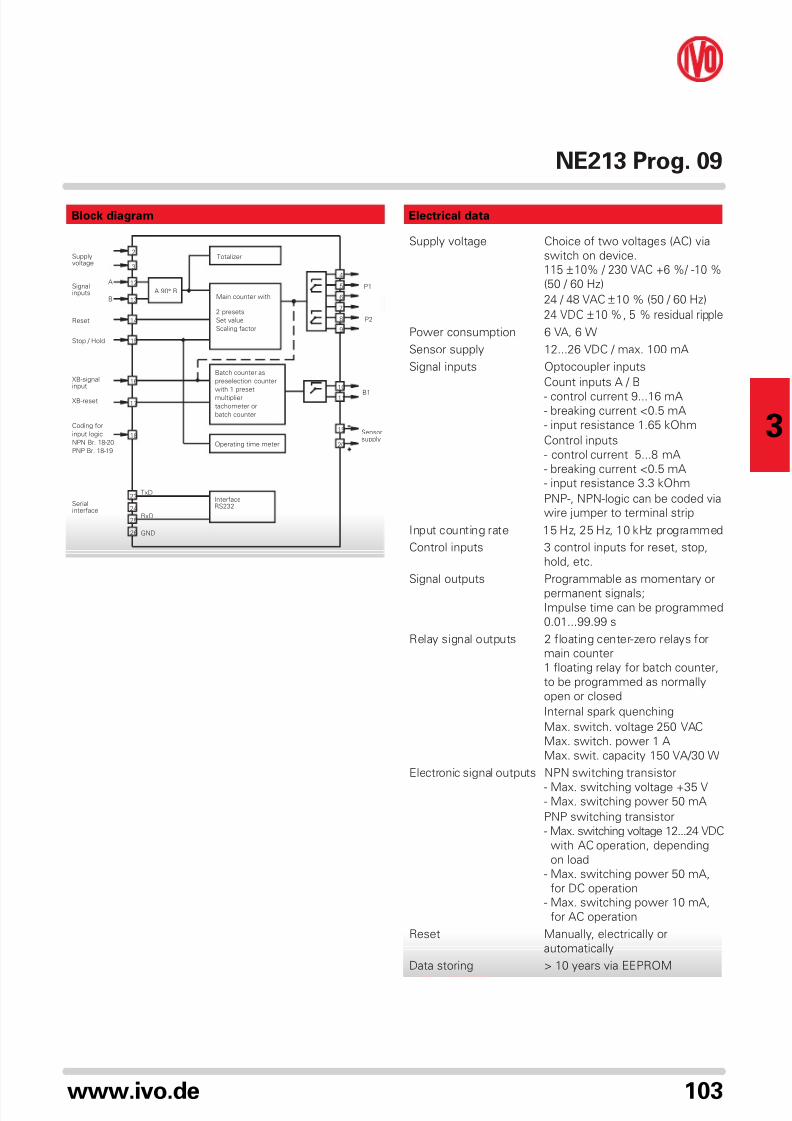
Block diagram Electrical data
Supply voltage Choice of two voltages (AC) via
switch on device.
115 ±10% / 230 VAC +6 %/ -10 %(50 / 60 Hz)
24 / 48 VAC ±10 % (50 / 60 Hz)
24 VDC ±10 %, 5 % residual ripple
Power consumption 6 VA, 6 W
Sensor supply 12...26 VDC / max. 100 mA
Signal inputs Optocoupler inputs
Count inputs A / B
- control current 9...16 mA- breaking current <0.5 mA
- input resistance 1.65 kOhm
Control inputs
- control current 5...8 mA
- breaking current <0.5 mA
- input resistance 3.3 kOhm
PNP-, NPN-logic can be coded via
wire jumper to terminal strip
Input counting rate 15 Hz, 25 Hz, 10 kHz programmed
Control inputs 3 control inputs for reset, stop,
hold, etc.
Signal outputs Programmable as momentary or
permanent signals;Impulse time can be programmed
0.01...99.99 s
Relay signal outputs 2 floating center-zero relays for
main counter
1 floating relay for batch counter,
to be programmed as normally
open or closed
Internal spark quenching
Max. switch. voltage 250 VAC
Max. switch. power 1 A
Max. swit. capacity 150 VA/30 W
Electronic signal outputs NPN switching transistor
- Max. switching voltage +35 V- Max. switching power 50 mA
PNP switching transistor
- Max. switching voltage 12...24 VDC
with AC operation, depending
on load
- Max. switching power 50 mA,
for DC operation
- Max. switching power 10 mA,
for AC operation
Reset Manually, electrically or
automatically
Data storing > 10 years via EEPROM
GND
Supplyvoltage
Signalinputs
Reset
Stop / Hold
XB-signalinput
XB-reset
A
B
Coding for
input logic
NPN Br. 18-20
PNP Br. 18-19
Serialinterface
InterfaceRS232
Operating time meter
B1
Sensorsupply
P1
P2
Totalizer
Main counter with
2 presets
Set value
Scaling factor
Batch counter as
preselection counter
with 1 presetmultiplier
tachometer or
batch counter
2
3
12
13
14
15
16
17
18
23
24
25
26
4
5
6
7
8
9
10
11
19
20
TxD
RxD
A 90° B
8/12/2019 Zmep Kat Ne213 e
http://slidepdf.com/reader/full/zmep-kat-ne213-e 3/6
NE213 Prog. 09
104 www.ivo.de
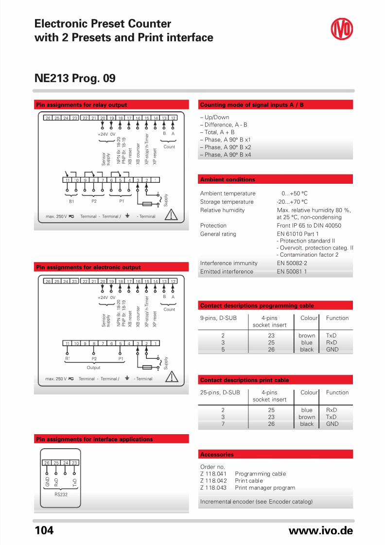
G N D
R x D
T x D
RS232
26 25 24 23
Pin assignments for interface applications
Ambient conditions
Ambient temperature 0...+50 °C
Storage temperature -20...+70 °C
Relative humidity Max. relative humidity 80 %,
at 25 °C, non-condensing
Protection Front IP 65 to DIN 40050
General rating EN 61010 Part 1
- Protection standard II
- Overvolt. protection categ. II
- Contamination factor 2
Interference immunity EN 50082-2
Emitted interference EN 50081-1
Counting mode of signal inputs A / B
– Up/Down
– Difference, A - B
– Total, A + B
– Phase, A 90° B x1
– Phase, A 90° B x2
– Phase, A 90° B x4
Pin assignments for relay output
Pin assignments for electronic output
Contact descriptions programming cable
9-pins, D-SUB 4-pins Colour Function
socket insert
2 23 brown TxD
3 25 blue RxD
5 26 black GND
Contact descriptions print cable
25-pins, D-SUB 4-pins Colour Function
socket insert
2 25 blue RxD
3 23 brown TxD
7 26 black GND
Accessories
Order no.
Z 118.041 Programming cable
Z 118.042 Print cable
Z 118.043 Print manager program
Incremental encoder (see Encoder catalog)
B1
Output
P2 P1
max. 250 V
AB+24V 0V
23
12131415161718212223242526
4567891011
1920
1
Terminal - Terminal / - Terminal
Count
S e n s o r
s u p p l y
N P N B r . 1 8 - 2 0
P N P B r . 1 8 - 1 9
X B r e s e t
X B c o u n t e r
X P - s t o p / h - T i m e r
X P r e s e t
S u p p l y
max. 250 V Terminal - Terminal / - Terminal
AB
Count
+24V 0V
S e n s o r
s u p p l y
N P N B r . 1 8 - 2 0
P N P B r . 1 8 - 1 9
X B r e s e t
X B c o u n t e r
X P - s t o p / h - T i m e r
X P r e s e t
S u p p l y
26 25 24 23 22 21 20 19 18 17 16 15 1314 12
11 10 9 8 7 6 5 4 3 2 1
B1 P2 P1
Electronic Preset Counter
with 2 Presets and Print interface
8/12/2019 Zmep Kat Ne213 e
http://slidepdf.com/reader/full/zmep-kat-ne213-e 4/6
NE213 Prog. 09
105www.ivo.de
3
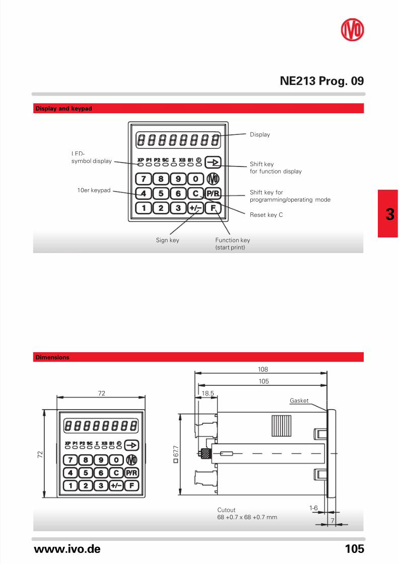
72
108
105
18.5
7 2
1-6
7
6 7 .
7
Display and keypad
Dimensions
Function key
(start print)
Shift key for
programming/operating mode
Reset key C
Sign key
10er keypad
Shift key
for function display
LED-
symbol display
Display
Cutout
68 +0.7 x 68 +0.7 mm
Gasket
8/12/2019 Zmep Kat Ne213 e
http://slidepdf.com/reader/full/zmep-kat-ne213-e 5/6
NE213 Prog. 09
106 www.ivo.de
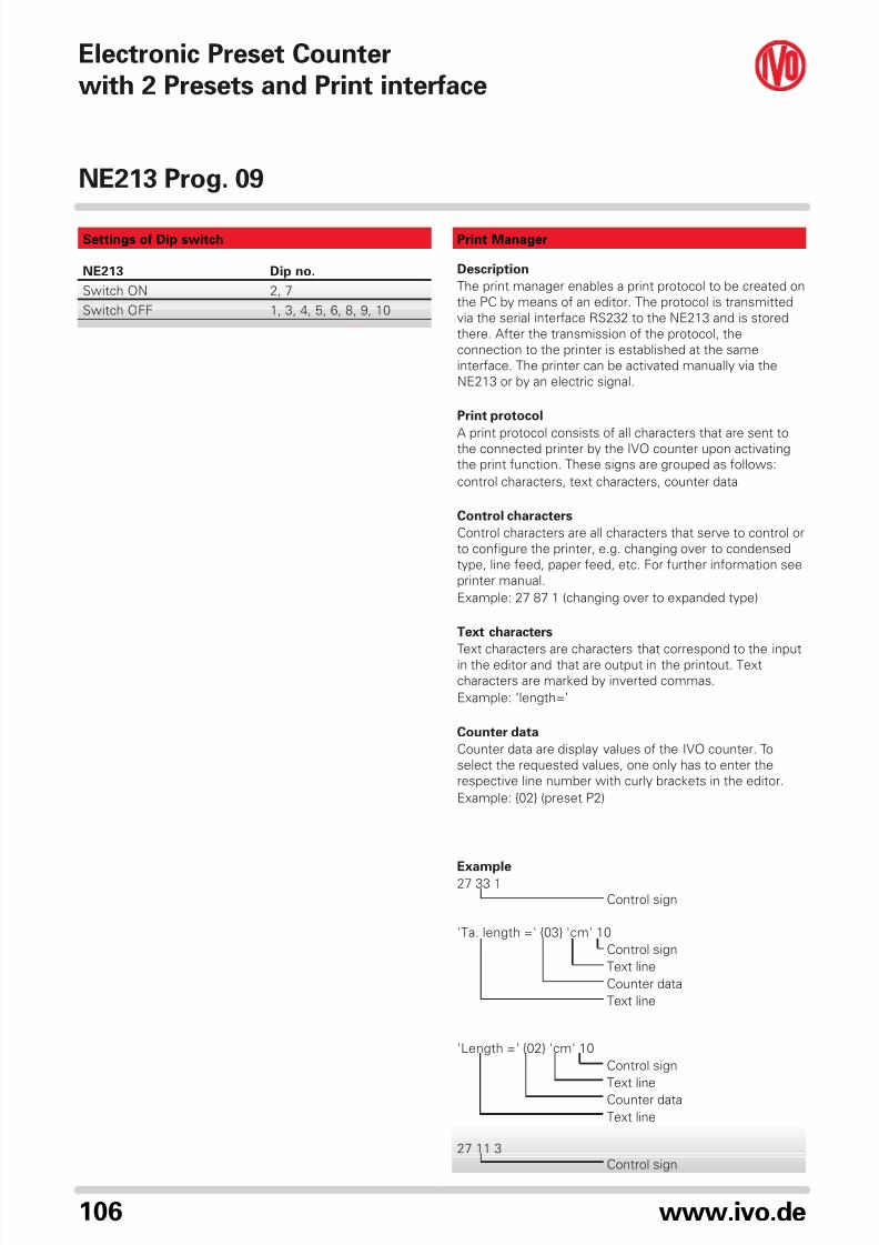
Print Manager
Description
The print manager enables a print protocol to be created on
the PC by means of an editor. The protocol is transmitted
via the serial interface RS232 to the NE213 and is stored
there. After the transmission of the protocol, the
connection to the printer is established at the same
interface. The printer can be activated manually via the
NE213 or by an electric signal.
Print protocol
A print protocol consists of all characters that are sent tothe connected printer by the IVO counter upon activating
the print function. These signs are grouped as follows:
control characters, text characters, counter data
Control characters
Control characters are all characters that serve to control or
to configure the printer, e.g. changing over to condensed
type, line feed, paper feed, etc. For further information see
printer manual.
Example: 27 87 1 (changing over to expanded type)
Text characters
Text characters are characters that correspond to the inputin the editor and that are output in the printout. Text
characters are marked by inverted commas.
Example: ‘length=’
Counter data
Counter data are display values of the IVO counter. To
select the requested values, one only has to enter the
respective line number with curly brackets in the editor.
Example: {02} (preset P2)
Example27 33 1
Control sign
'Ta. length =' {03} 'cm' 10
Control sign
Text line
Counter data
Text line
'Length =' {02} 'cm' 10
Control sign
Text line
Counter data
Text line
27 11 3
Control sign
Settings of Dip switch
NE213 Dip no.
Switch ON 2, 7
Switch OFF 1, 3, 4, 5, 6, 8, 9, 10
Electronic Preset Counter
with 2 Presets and Print interface
8/12/2019 Zmep Kat Ne213 e
http://slidepdf.com/reader/full/zmep-kat-ne213-e 6/6
NE213 Prog. 09
107www.ivo.de
3


