
Continuous Batch WasherDispenser Installation
Scope of presentation
1. Dispenser options
2. Which dispenser to pick
3. Summit XL tunnel mode comparison
4. Summit XL TAFS wiring and programming
5. Summit XL tunnel flush
6. ILS Max T installation
7. ILS Max T programming
8. Troubleshooting
9. ManageNet Reports
Continuous Batch Washer
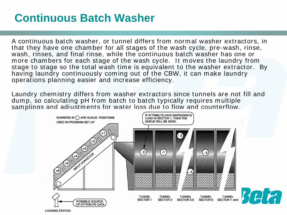
A continuous batch washer, or tunnel differs from normal washer extractors, in that they have one chamber for all stages of the wash cycle, pre-wash, rinse, wash, rinses, and final rinse, while the continuous batch washer has one or more chambers for each stage of the wash cycle. It moves the laundry from stage to stage so the total wash time is equivalent to the washer extractor. By having laundry continuously coming out of the CBW, it can make laundry operations planning easier and increase efficiency.
Laundry chemistry differs from washer extractors since tunnels are not fill and dump, so calculating pH from batch to batch typically requires multiple samplings and adjustments for water loss due to flow and counterflow.
Dispenser Options
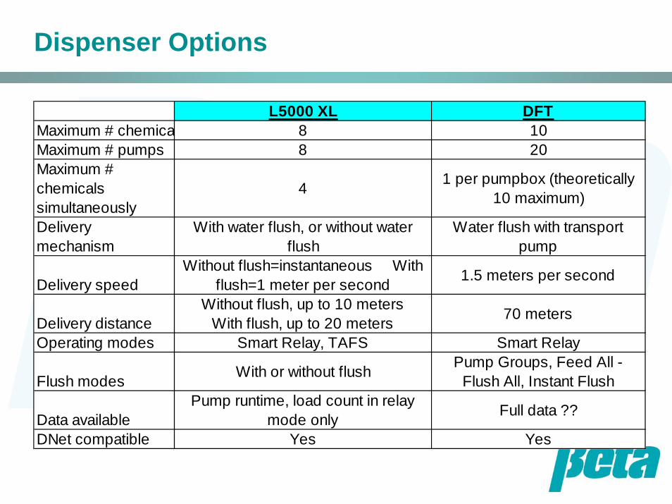
L5000 XL DFTMaximum # chemica 8 10Maximum # pumps 8 20Maximum # chemicals simultaneously
4 1 per pumpbox (theoretically 10 maximum)
Delivery mechanism
With water flush, or without water flush
Water flush with transport pump
Delivery speedWithout flush=instantaneous With
flush=1 meter per second 1.5 meters per second
Delivery distanceWithout flush, up to 10 meters
With flush, up to 20 meters 70 meters
Operating modes Smart Relay, TAFS Smart Relay
Flush modes With or without flush Pump Groups, Feed All - Flush All, Instant Flush
Data availablePump runtime, load count in relay
mode only Full data ??
DNet compatible Yes Yes
XL Operating Mode Comparison
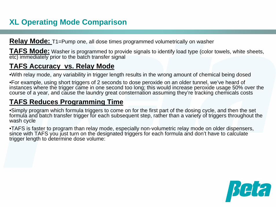
Relay Mode: T1=Pump one, all dose times programmed volumetrically on washer
TAFS Mode: Washer is programmed to provide signals to identify load type (color towels, white sheets, etc) immediately prior to the batch transfer signal
TAFS Accuracy vs. Relay Mode•With relay mode, any variability in trigger length results in the wrong amount of chemical being dosed•For example, using short triggers of 2 seconds to dose peroxide on an older tunnel, we’ve heard of instances where the trigger came in one second too long; this would increase peroxide usage 50% over the course of a year, and cause the laundry great consternation assuming they’re tracking chemicals costs
TAFS Reduces Programming Time•Simply program which formula triggers to come on for the first part of the dosing cycle, and then the set formula and batch transfer trigger for each subsequent step, rather than a variety of triggers throughout the wash cycle•TAFS is faster to program than relay mode, especially non-volumetric relay mode on older dispensers, since with TAFS you just turn on the designated triggers for each formula and don’t have to calculate trigger length to determine dose volume:
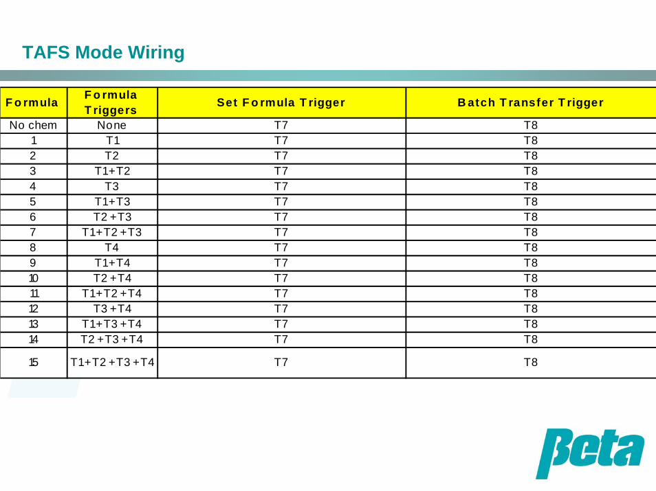
TAFS Mode Wiring
F o rmula F o rmula T riggers Set F o rmula T rigger B atch T ransfer T rigger
No chem None T7 T81 T1 T7 T82 T2 T7 T83 T1 + T2 T7 T84 T3 T7 T85 T1 + T3 T7 T86 T2 + T3 T7 T87 T1 + T2 + T3 T7 T88 T4 T7 T89 T1 + T4 T7 T810 T2 + T4 T7 T811 T1 + T2 + T4 T7 T812 T3 + T4 T7 T813 T1 + T3 + T4 T7 T814 T2 + T3 + T4 T7 T8
15 T1 + T2 + T3 + T4 T7 T8
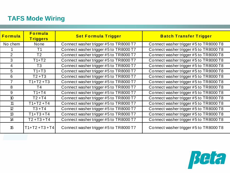
TAFS Mode Wiring
F o rmula F o rmula T riggers Set F o rmula T rigger B atch T ransfer T rigger
No chem None Connect washer trigger #5 to TR8000 T7 Connect washer trigger #5 to TR8000 T81 T1 Connect washer trigger #5 to TR8000 T7 Connect washer trigger #5 to TR8000 T82 T2 Connect washer trigger #5 to TR8000 T7 Connect washer trigger #5 to TR8000 T83 T1 + T2 Connect washer trigger #5 to TR8000 T7 Connect washer trigger #5 to TR8000 T84 T3 Connect washer trigger #5 to TR8000 T7 Connect washer trigger #5 to TR8000 T85 T1 + T3 Connect washer trigger #5 to TR8000 T7 Connect washer trigger #5 to TR8000 T86 T2 + T3 Connect washer trigger #5 to TR8000 T7 Connect washer trigger #5 to TR8000 T87 T1 + T2 + T3 Connect washer trigger #5 to TR8000 T7 Connect washer trigger #5 to TR8000 T88 T4 Connect washer trigger #5 to TR8000 T7 Connect washer trigger #5 to TR8000 T89 T1 + T4 Connect washer trigger #5 to TR8000 T7 Connect washer trigger #5 to TR8000 T810 T2 + T4 Connect washer trigger #5 to TR8000 T7 Connect washer trigger #5 to TR8000 T811 T1 + T2 + T4 Connect washer trigger #5 to TR8000 T7 Connect washer trigger #5 to TR8000 T812 T3 + T4 Connect washer trigger #5 to TR8000 T7 Connect washer trigger #5 to TR8000 T813 T1 + T3 + T4 Connect washer trigger #5 to TR8000 T7 Connect washer trigger #5 to TR8000 T814 T2 + T3 + T4 Connect washer trigger #5 to TR8000 T7 Connect washer trigger #5 to TR8000 T8
15 T1 + T2 + T3 + T4 Connect washer trigger #5 to TR8000 T7 Connect washer trigger #5 to TR8000 T8
TAFS Mode Triggering
•For each formula, program the formula triggers required to come on from the washer for five seconds after the formula starts. Program the set formula trigger to come on for 5 seconds, five seconds after the formula triggers required shut off
•The set formula trigger must come on within 10 seconds of the last formula trigger, or no chemical will be dosed • The formula triggers must all occur more or less simultaneously. If there's a 10 second gap in between them, the wrong formula number will be set• Batch transfer and set formula trigger can be the same •TAFS doesn't log formulas as complete, so you shouldn't use the data PCB to log data in this mode. •TAFS MODE REQUIRES THE TR8000 AND WON'T WORK WITH TR6000
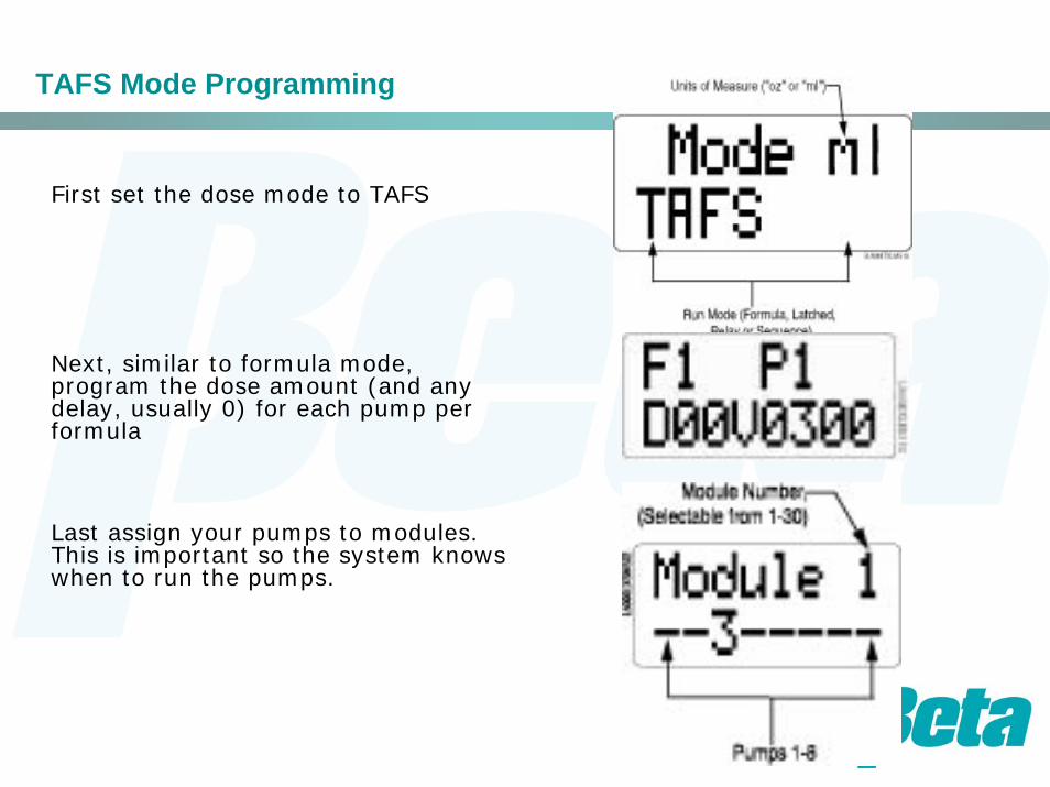
TAFS Mode Programming
First set the dose mode to TAFS
Next, similar to formula mode, program the dose amount (and any delay, usually 0) for each pump per formula
Last assign your pumps to modules. This is important so the system knows when to run the pumps.
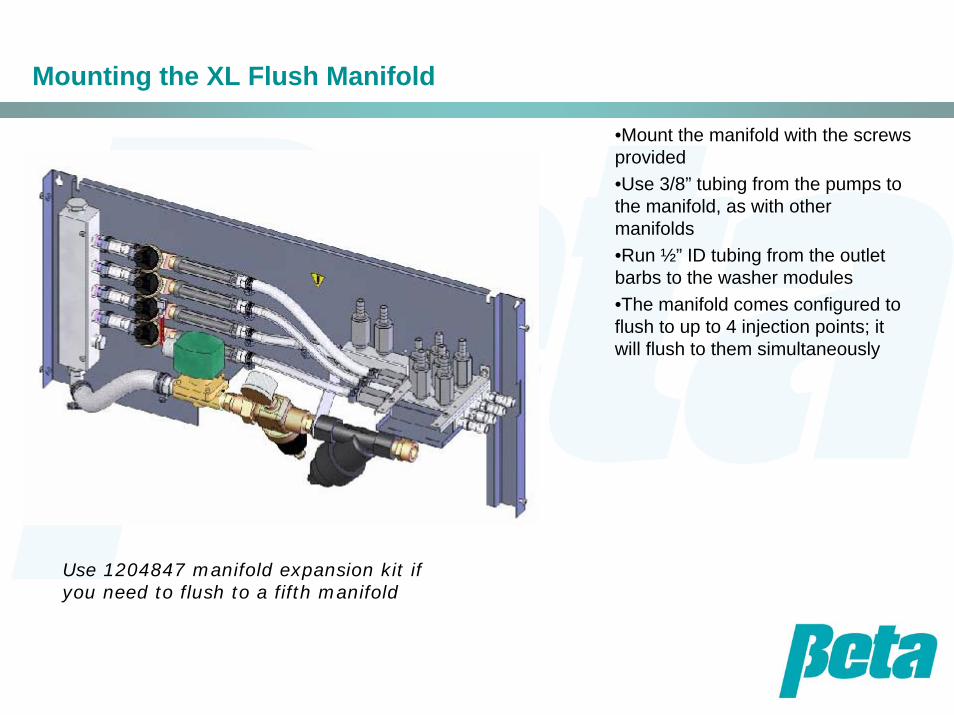
Mounting the XL Flush Manifold
•Mount the manifold with the screws provided•Use 3/8” tubing from the pumps to the manifold, as with other manifolds•Run ½” ID tubing from the outlet barbs to the washer modules•The manifold comes configured to flush to up to 4 injection points; it will flush to them simultaneously
Use 1204847 manifold expansion kit if you need to flush to a fifth manifold
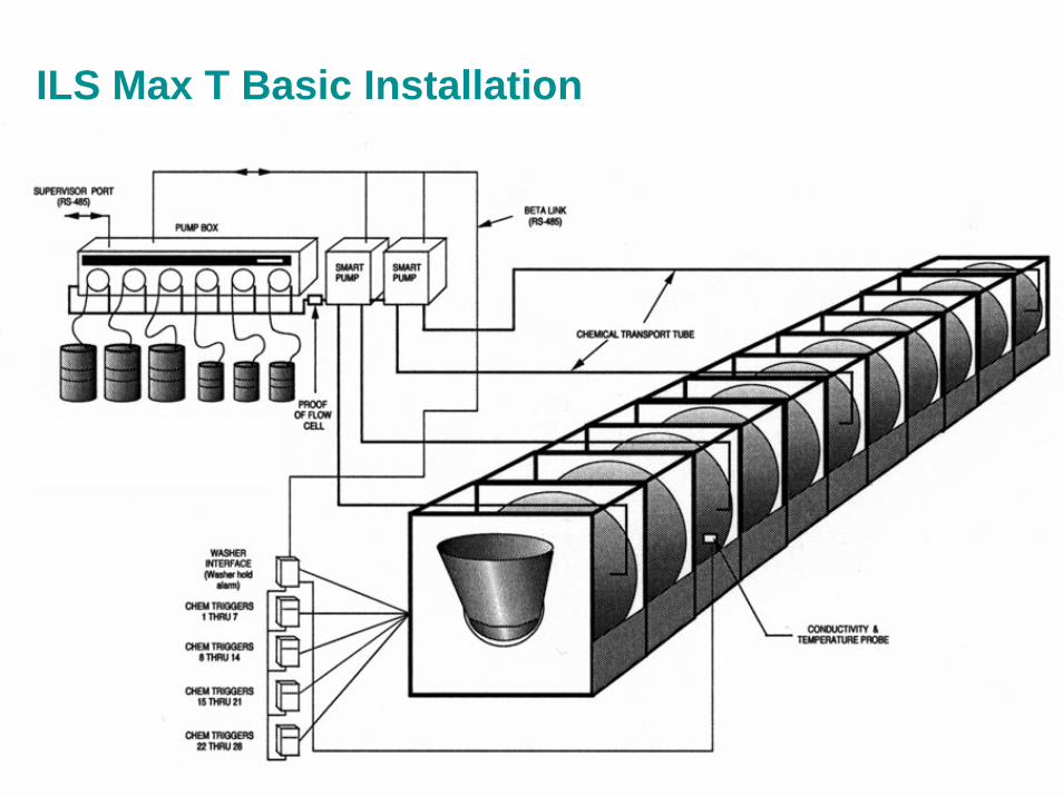
ILS Max T Basic Installation

ILS Max T Typical Installation
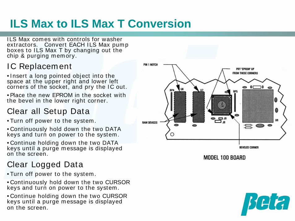
ILS Max to ILS Max T ConversionILS Max comes with controls for washer extractors. Convert EACH ILS Max pump boxes to ILS Max T by changing out the chip & purging memory.
IC Replacement•Insert a long pointed object into the space at the upper right and lower left corners of the socket, and pry the IC out.•Place the new EPROM in the socket with the bevel in the lower right corner.
Clear all Setup Data•Turn off power to the system.•Continuously hold down the two DATA keys and turn on power to the system.•Continue holding down the two DATA keys until a purge message is displayed on the screen.
Clear Logged Data•Turn off power to the system.•Continuously hold down the two CURSOR keys and turn on power to the system.•Continue holding down the two CURSOR keys until a purge message is displayed on the screen.

ILS Max T Wiring
•Run a separate power source for the master and slave pumpboxes.
•The master and slave are not wired together; the master does all datalogging, but it doesn’t control the slave units
•Each pumpbox, whether master or slave, uses one WIM
•Slave triggers are jumped both to the slave’s single TR7000 AC/DC and the master’s TR7000 AC/DC, enabling the slave to pump when these triggers occur and the master to log data when they occur.
•MNet is only connected to the master
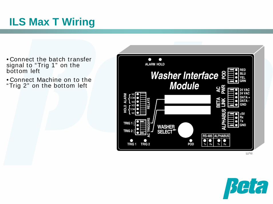
ILS Max T Wiring
•Connect the batch transfer signal to “Trig 1” on the bottom left•Connect Machine on to the “Trig 2” on the bottom left
ILS Max T Programming
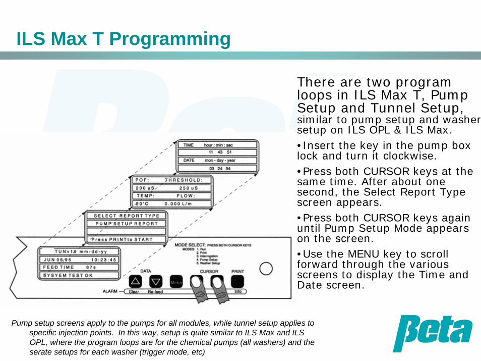
There are two program loops in ILS Max T, Pump Setup and Tunnel Setup, similar to pump setup and washer setup on ILS OPL & ILS Max.•Insert the key in the pump box lock and turn it clockwise.•Press both CURSOR keys at the same time. After about one second, the Select Report Type screen appears. •Press both CURSOR keys again until Pump Setup Mode appears on the screen.•Use the MENU key to scroll forward through the various screens to display the Time and Date screen.
Pump setup screens apply to the pumps for all modules, while tunnel setup applies to specific injection points. In this way, setup is quite similar to ILS Max and ILS OPL, where the program loops are for the chemical pumps (all washers) and the serate setups for each washer (trigger mode, etc)
ILS Max T Programming: Pump Setup
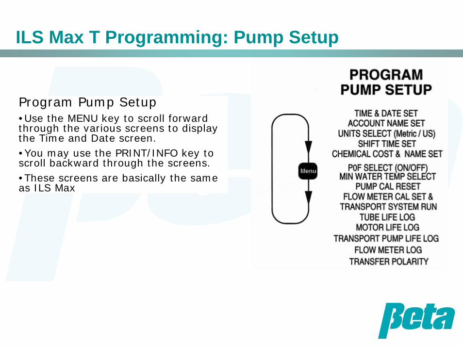
Program Pump Setup•Use the MENU key to scroll forward through the various screens to display the Time and Date screen.•You may use the PRINT/INFO key to scroll backward through the screens. •These screens are basically the same as ILS Max
Washer Setup Programming
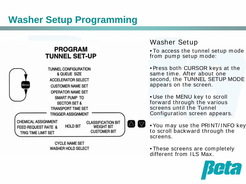
Washer Setup•To access the tunnel setup mode from pump setup mode:
•Press both CURSOR keys at the same time. After about one second, the TUNNEL SETUP MODE appears on the screen.
•Use the MENU key to scroll forward through the various screens until the Tunnel Configuration screen appears.
•You may use the PRINT/INFO key to scroll backward through the screens.
•These screens are completely different from ILS Max.
Programming Tunnel Configuration
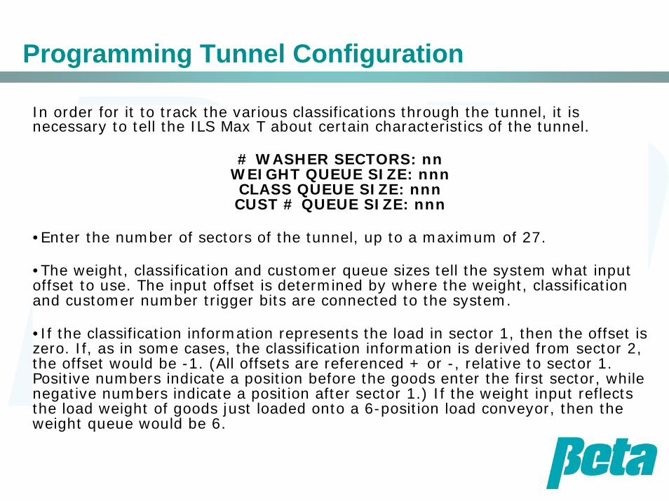
In order for it to track the various classifications through the tunnel, it is necessary to tell the ILS Max T about certain characteristics of the tunnel.
# WASHER SECTORS: nnWEIGHT QUEUE SIZE: nnnCLASS QUEUE SIZE: nnnCUST # QUEUE SIZE: nnn
•Enter the number of sectors of the tunnel, up to a maximum of 27.
•The weight, classification and customer queue sizes tell the system what input offset to use. The input offset is determined by where the weight, classification and customer number trigger bits are connected to the system.
•If the classification information represents the load in sector 1, then the offset is zero. If, as in some cases, the classification information is derived from sector 2, the offset would be -1. (All offsets are referenced + or -, relative to sector 1. Positive numbers indicate a position before the goods enter the first sector, while negative numbers indicate a position after sector 1.) If the weight input reflects the load weight of goods just loaded onto a 6-position load conveyor, then the weight queue would be 6.
Transport or “Accelerator Setup”
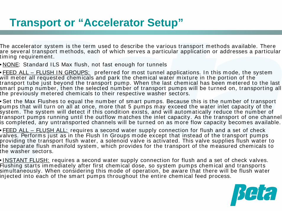
The accelerator system is the term used to describe the various transport methods available. There are several transport methods, each of which serves a particular application or addresses a particular timing requirement.•NONE: Standard ILS Max flush, not fast enough for tunnels•FEED ALL – FLUSH IN GROUPS: preferred for most tunnel applications. In this mode, the system will meter all requested chemicals and park the chemical water mixture in the portion of the transport tube just beyond the transport pump. When the last chemical has been metered to the last smart pump number, then the selected number of transport pumps will be turned on, transporting all the previously metered chemicals to their respective washer sectors.•Set the Max Flushes to equal the number of smart pumps. Because this is the number of transport pumps that will turn on all at once, more that 5 pumps may exceed the water inlet capacity of the system. The system will detect if this condition exists, and will automatically reduce the number of transport pumps running until the outflow matches the inlet capacity. As the transport of one channel is completed, any untransported channels will be turned on as more flow capacity becomes available.•FEED ALL – FLUSH ALL: requires a second water supply connection for flush and a set of check valves. Performs just as in the Flush In Groups mode except that instead of the transport pumps providing the transport flush water, a solenoid valve is activated. This valve supplies flush water to the separate flush manifold system, which provides for the transport of the measured chemicals to the washer sectors.
•INSTANT FLUSH: requires a second water supply connection for flush and a set of check valves.Flushing starts immediately after first chemical dose, so system pumps chemical and transports simultaneously. When considering this mode of operation, be aware that there will be flush water injected into each of the smart pumps throughout the entire chemical feed process.

Smart Pump Setup
•This setting is important so the ILS Max T knows which tunnel module the smart pump is assigned to, so it will pump at the right time.
SMART PUMP: nnWASHER SECTOR: nn
TRANSPORT TIME : ##
•Smart pump=transport pump
•Washer sector=tunnel module
•So, if smart pump #3 injects into tunnel module number 5, set smart pump to 3 and washer sector to 5.
•You will also use this screen to enter the transport time in seconds. Use 5 feet per second from the pumpbox to the injection point.
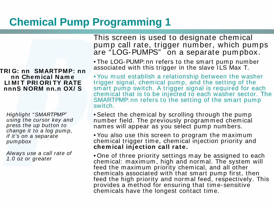
Chemical Pump Programming 1This screen is used to designate chemical pump call rate, trigger number, which pumps are “LOG-PUMPS” on a separate pumpbox.•The LOG-PUMP:nn refers to the smart pump number associated with this trigger in the slave ILS Max T. •You must establish a relationship between the washer trigger signal, chemical pump, and the setting of the smart pump switch. A trigger signal is required for each chemical that is to be injected to each washer sector. The SMARTPMP:nn refers to the setting of the smart pump switch.•Select the chemical by scrolling through the pump number field. The previously programmed chemical names will appear as you select pump numbers.•You also use this screen to program the maximum chemical trigger time, chemical injection priority and chemical injection call rate.•One of three priority settings may be assigned to each chemical: maximum, high and normal. The system will feed the maximum priority chemical, and all other chemicals associated with that smart pump first, then feed the high priority and normal feed, respectively. This provides a method for ensuring that time-sensitive chemicals have the longest contact time.
TRIG: nn SMARTPMP: nnnn Chemical Name
LIMIT PRIORITY RATEnnnS NORM nn.n OX/S
Highlight “SMARTPMP” using the cursor key and press the up button to change it to a log pump, if it’s on a separate pumpbox
Always use a call rate of 1.0 oz or greater
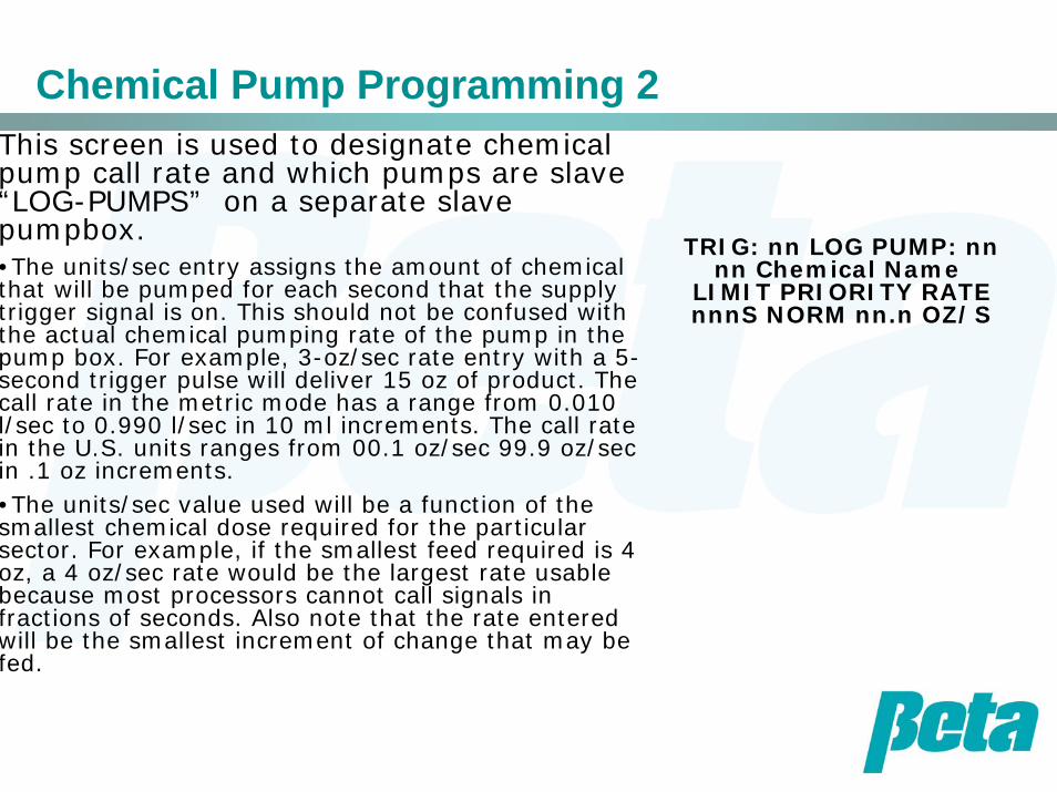
Chemical Pump Programming 2This screen is used to designate chemical pump call rate and which pumps are slave “LOG-PUMPS” on a separate slave pumpbox.•The units/sec entry assigns the amount of chemical that will be pumped for each second that the supply trigger signal is on. This should not be confused with the actual chemical pumping rate of the pump in the pump box. For example, 3-oz/sec rate entry with a 5-second trigger pulse will deliver 15 oz of product. The call rate in the metric mode has a range from 0.010 l/sec to 0.990 l/sec in 10 ml increments. The call rate in the U.S. units ranges from 00.1 oz/sec 99.9 oz/sec in .1 oz increments.•The units/sec value used will be a function of the smallest chemical dose required for the particular sector. For example, if the smallest feed required is 4 oz, a 4 oz/sec rate would be the largest rate usable because most processors cannot call signals in fractions of seconds. Also note that the rate entered will be the smallest increment of change that may be fed.
TRIG: nn LOG PUMP: nnnn Chemical Name
LIMIT PRIORITY RATEnnnS NORM nn.n OZ/S
MNet Programming
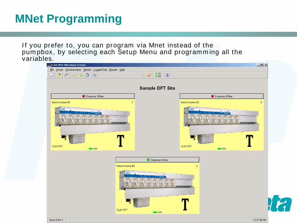
If you prefer to, you can program via Mnet instead of the pumpbox, by selecting each Setup Menu and programming all the variables.
MNet Programming
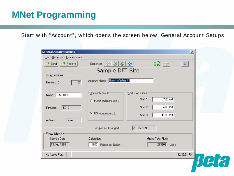
Start with “Account”, which opens the screen below, General Account Setups

MNet Programming
Continue with General Tunnel Configuration Setups
MNet Programming
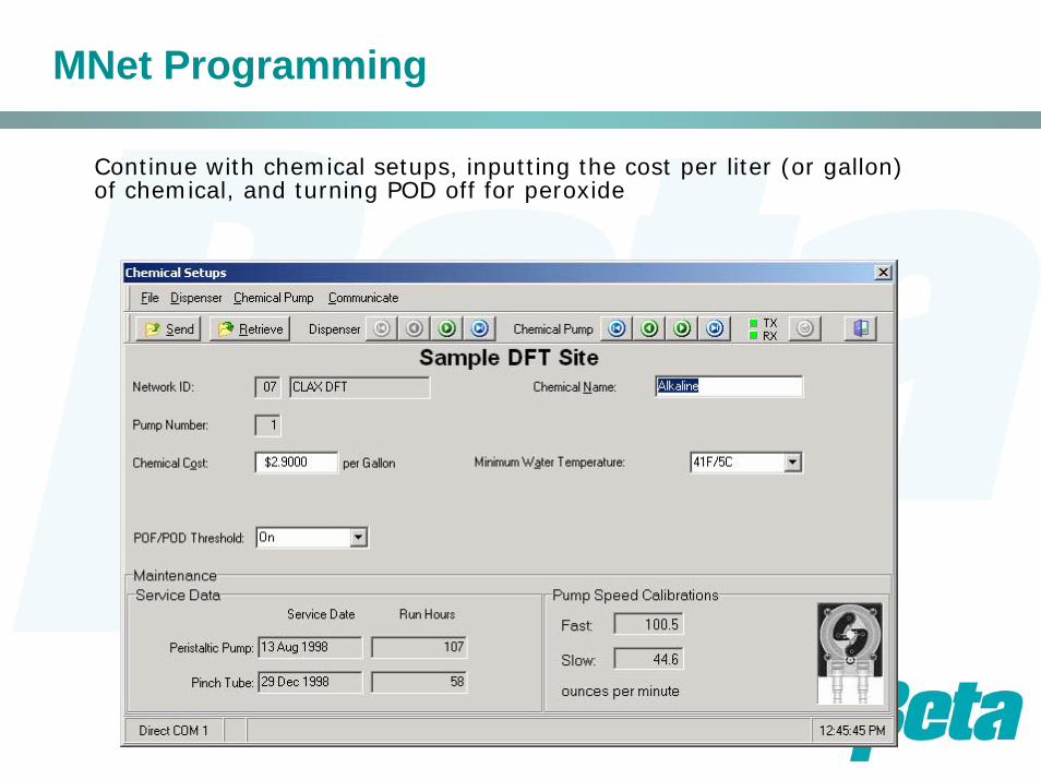
Continue with chemical setups, inputting the cost per liter (or gallon) of chemical, and turning POD off for peroxide
MNet Programming
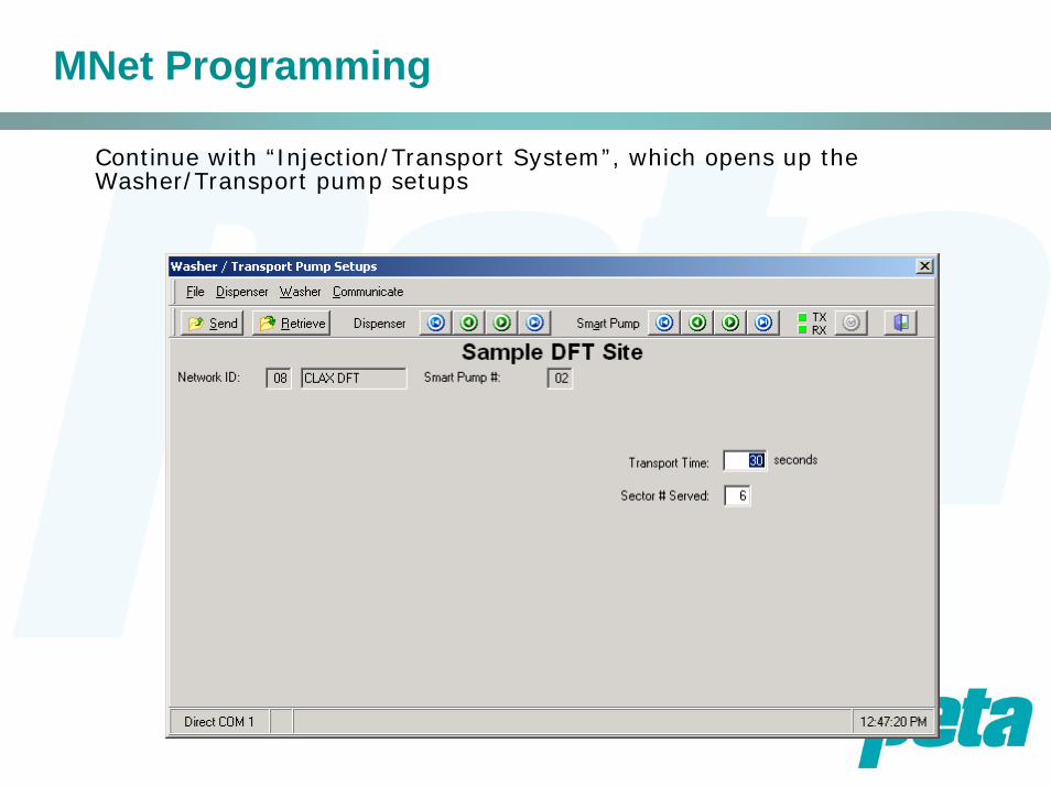
Continue with “Injection/Transport System”, which opens up the Washer/Transport pump setups
MNet Programming
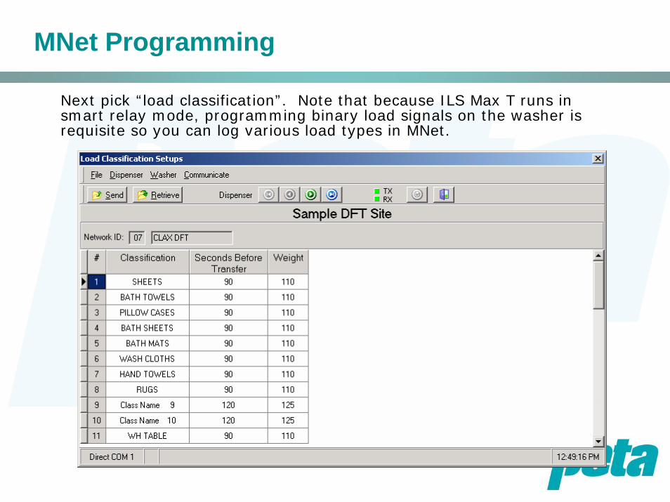
Next pick “load classification”. Note that because ILS Max T runs in smart relay mode, programming binary load signals on the washer is requisite so you can log various load types in MNet.

MNet Programming
Next pick “Trigger”, which opens up the “Feed Triggering Setups”screen shown below. Use “Trigger Use” to select which signals will be chemical triggers, which chemical pump they will run, and which smart transport pump they will be assigned to.
MNet Programming
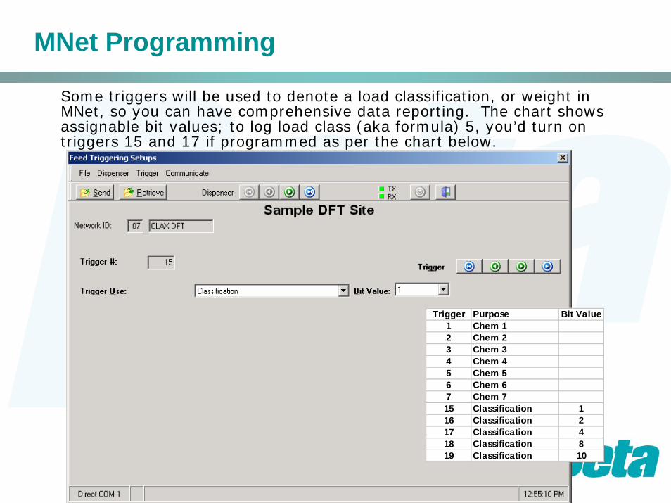
Some triggers will be used to denote a load classification, or weight in MNet, so you can have comprehensive data reporting. The chart shows assignable bit values; to log load class (aka formula) 5, you’d turn on triggers 15 and 17 if programmed as per the chart below.
Trigger Purpose Bit Value1 Chem 12 Chem 23 Chem 34 Chem 45 Chem 56 Chem 6 7 Chem 715 Classification 116 Classification 217 Classification 418 Classification 819 Classification 10

MNet Programming
Similar to load classification, with weight you turn on some triggers to show an amount of weight. For example with it set up as per the chart below, we’d have the tunnel emit triggers 9 & 14 to log a weight of 90.
Trigger Purpose Bit Value8 Weight 89 Weight 1010 Weight 1611 Weight 3212 Weight 4013 Weight 6414 Weight 8015 Classification 116 Classification 217 Classification 418 Classification 819 Classification 10

MNet Programming
Other trigger uses include being a “log pump”, as shown on the left, or a customer number. The log pump is used when a second ILS Max T will feed the chemical, and the trigger is tied to both the master data unit and the secondary unit, which will feed the dose.
MNet Programming
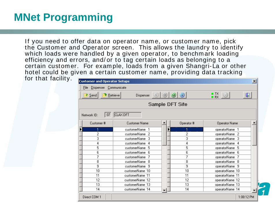
If you need to offer data on operator name, or customer name, pick the Customer and Operator screen. This allows the laundry to identify which loads were handled by a given operator, to benchmark loading efficiency and errors, and/or to tag certain loads as belonging to a certain customer. For example, loads from a given Shangri-La or other hotel could be given a certain customer name, providing data tracking for that facility.
Troubleshooting
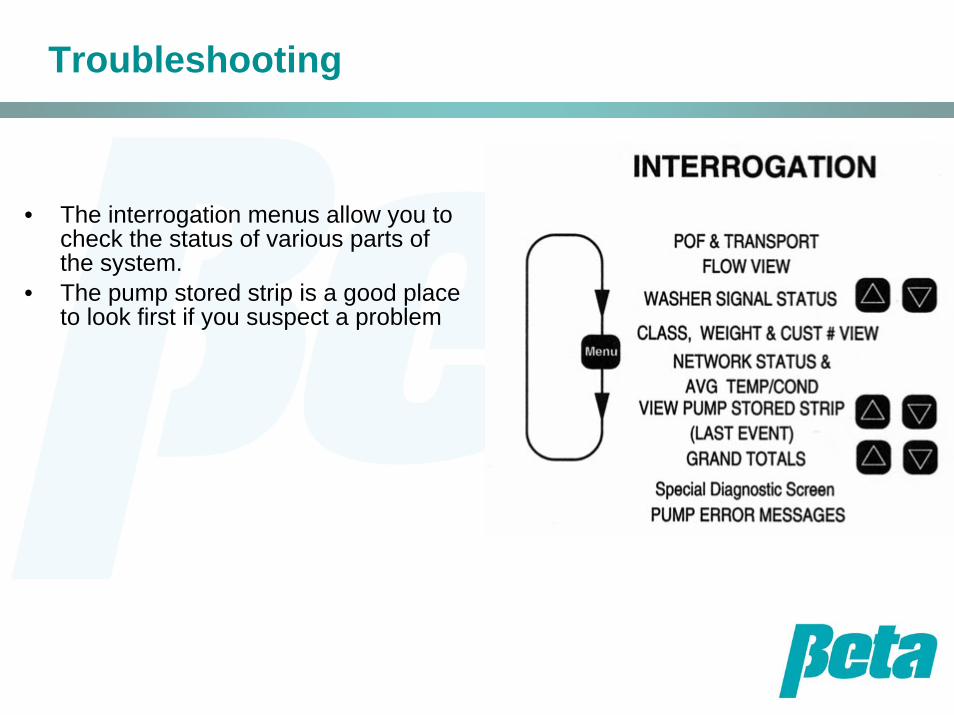
• The interrogation menus allow you to check the status of various parts of the system.
• The pump stored strip is a good place to look first if you suspect a problem
Pump Stored Strip
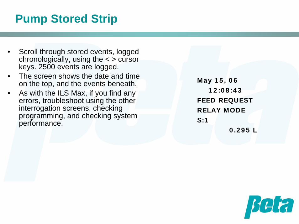
• Scroll through stored events, logged chronologically, using the < > cursor keys. 2500 events are logged.
• The screen shows the date and time on the top, and the events beneath.
• As with the ILS Max, if you find any errors, troubleshoot using the other interrogation screens, checking programming, and checking system performance.
May 15, 0612:08:43
FEED REQUESTRELAY MODES:1
0.295 L
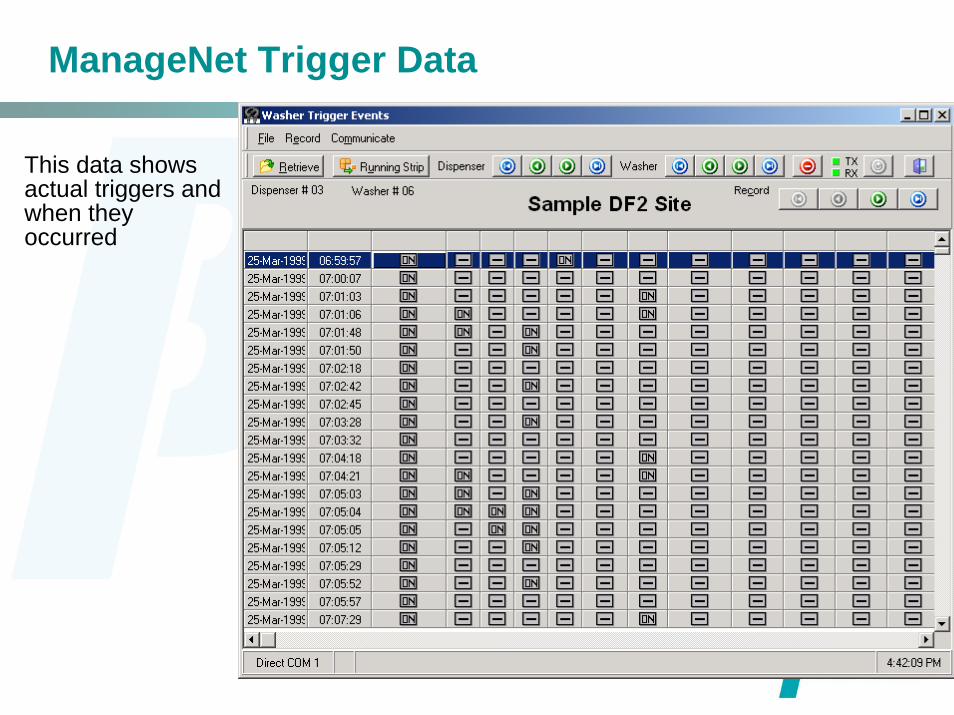
ManageNet Trigger Data
This data shows actual triggers and when they occurred
ManageNet Data
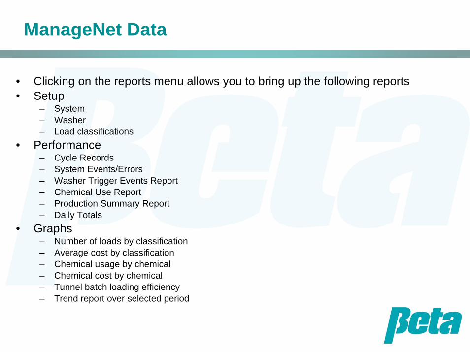
• Clicking on the reports menu allows you to bring up the following reports• Setup
– System– Washer – Load classifications
• Performance– Cycle Records– System Events/Errors– Washer Trigger Events Report– Chemical Use Report– Production Summary Report– Daily Totals
• Graphs– Number of loads by classification– Average cost by classification– Chemical usage by chemical– Chemical cost by chemical– Tunnel batch loading efficiency– Trend report over selected period
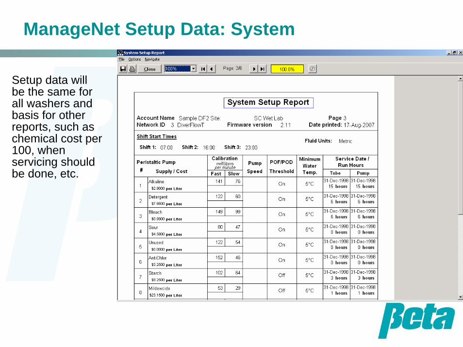
ManageNet Setup Data: System
Setup data will be the same for all washers and basis for other reports, such as chemical cost per 100, when servicing should be done, etc.

ManageNet Setup Data: Washer
Shows transport time per washer, or per tunnel moduleFor washer extractors, shows trigger polarity and other data such as relay mode call rate
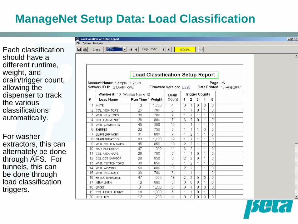
ManageNet Setup Data: Load Classification
Each classification should have a different runtime, weight, and drain/trigger count, allowing the dispenser to track the various classifications automatically.
For washer extractors, this can alternately be done through AFS. For tunnels, this can be done through load classification triggers.
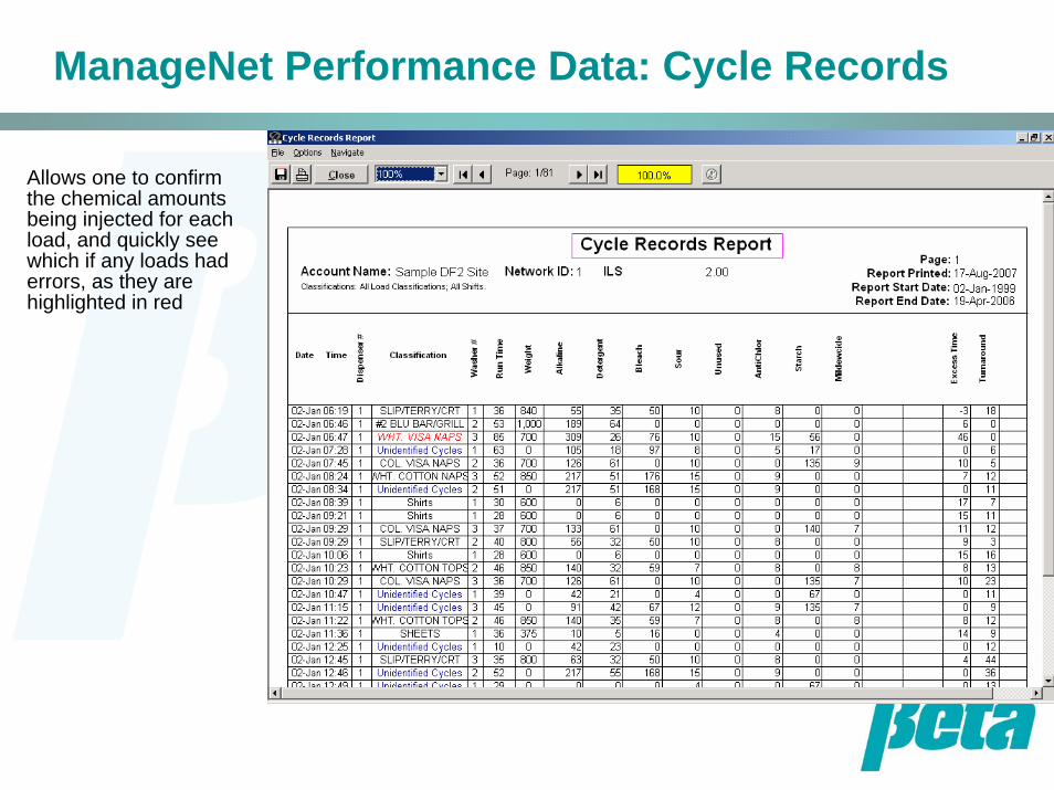
ManageNet Performance Data: Cycle Records
Allows one to confirm the chemical amounts being injected for each load, and quickly see which if any loads had errors, as they are highlighted in red

ManageNet Performance Data: System Events
System events data can be used for troubleshooting or optimizing wash quality
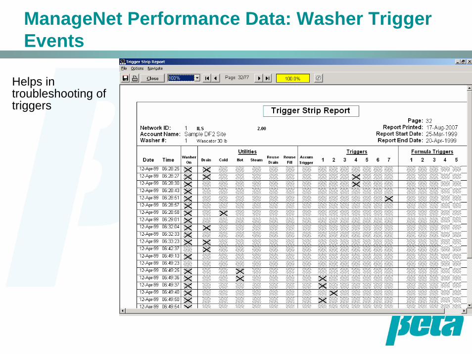
ManageNet Performance Data: Washer Trigger Events
Helps in troubleshooting of triggers
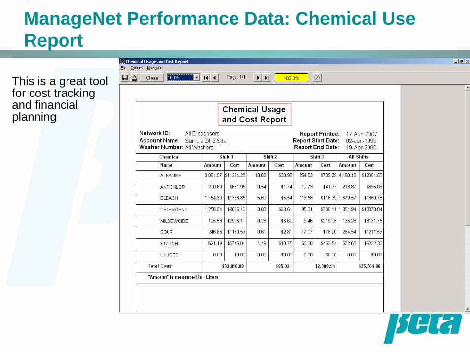
ManageNet Performance Data: Chemical Use Report
This is a great tool for cost tracking and financial planning
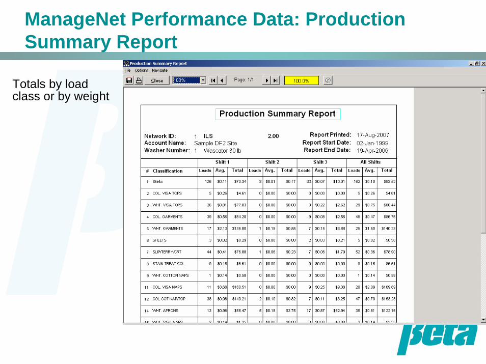
ManageNet Performance Data: Production Summary Report
Totals by load class or by weight

ManageNet Performance Data: Daily Totals
Shows classifications, chemical costs, utilities, hold time, excess time, and cost per 100 kilos.
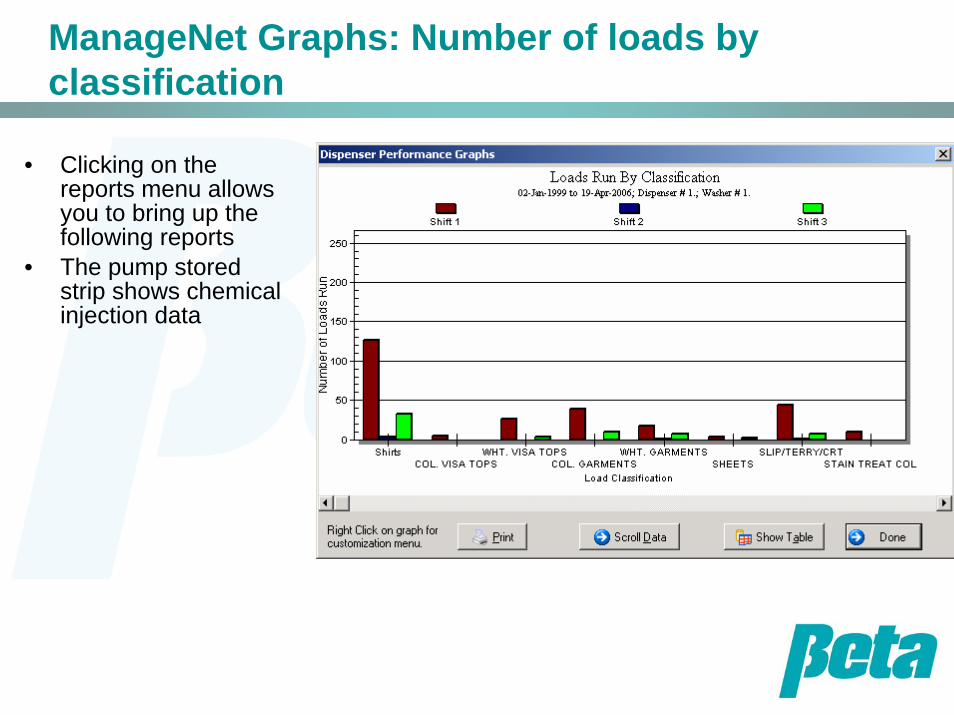
ManageNet Graphs: Number of loads by classification
• Clicking on the reports menu allows you to bring up the following reports
• The pump stored strip shows chemical injection data
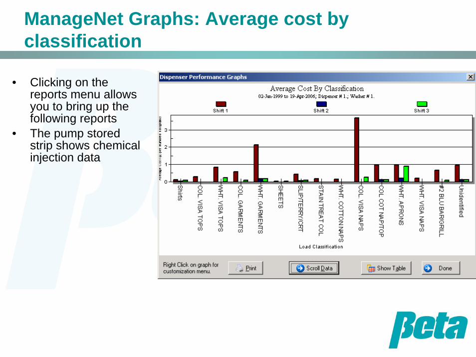
ManageNet Graphs: Average cost by classification
• Clicking on the reports menu allows you to bring up the following reports
• The pump stored strip shows chemical injection data
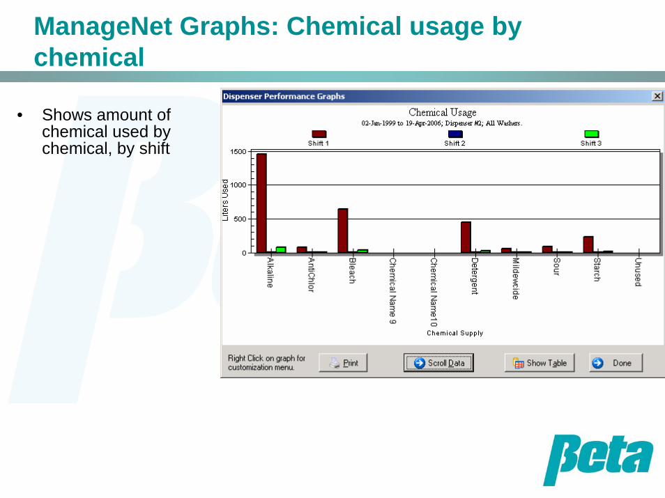
ManageNet Graphs: Chemical usage by chemical
• Shows amount of chemical used by chemical, by shift
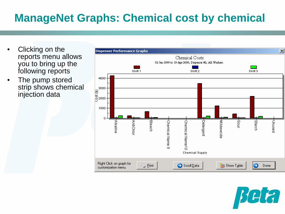
ManageNet Graphs: Chemical cost by chemical
• Clicking on the reports menu allows you to bring up the following reports
• The pump stored strip shows chemical injection data

ManageNet Graphs: Tunnel batch loading efficiency
• Clicking on the reports menu allows you to bring up the following reports
• The pump stored strip shows chemical injection data
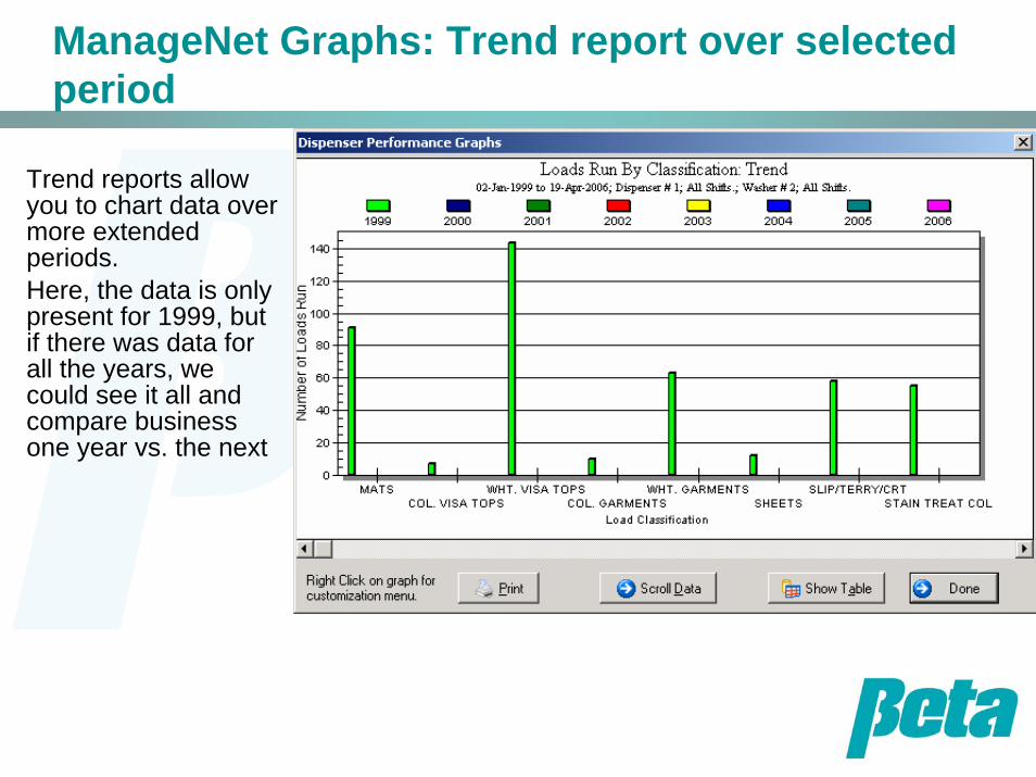
ManageNet Graphs: Trend report over selected period
Trend reports allow you to chart data over more extended periods.Here, the data is only present for 1999, but if there was data for all the years, we could see it all and compare business one year vs. the next

Continuous Batch WasherDispenser Installation


