Integration Manual Ultra3000 Digital Servo Drives (Catalog Numbers 2098-DSD-005, -010, and -020 2098-DSD-xxxX 2098-DSD-xxx-SE 2098-DSD-xxx-DN 2098-DSD-xxxX-DN 2098-DSD-030, -075, and -150 2098-DSD-xxxX 2098-DSD-xxx-SE 2098-DSD-xxx-DN 2098-DSD-xxxX-DN 2098-DSD-HV030, -HV050, -HV100, -HV150, and -HV220 2098-DSD-HVxxxX 2098-DSD-HVxxx-SE 2098-DSD-HVxxx-DN 2098-DSD-HVxxxX-DN)
Transcript
Integration Manual
Ultra3000 Digital Servo Drives
(Catalog Numbers 2098-DSD-005, -010, and -020 2098-DSD-xxxX 2098-DSD-xxx-SE 2098-DSD-xxx-DN 2098-DSD-xxxX-DN 2098-DSD-030, -075, and -150 2098-DSD-xxxX 2098-DSD-xxx-SE 2098-DSD-xxx-DN 2098-DSD-xxxX-DN 2098-DSD-HV030, -HV050, -HV100, -HV150, and -HV220 2098-DSD-HVxxxX 2098-DSD-HVxxx-SE 2098-DSD-HVxxx-DN 2098-DSD-HVxxxX-DN)
Important User Information Because of the variety of uses for the products described in this publication, those responsible for the application and use of this control equipment must satisfy themselves that all necessary steps have been taken to assure that each application and use meets all performance and safety requirements, including any applicable laws, regulations, codes and standards.
The illustrations, charts, sample programs and layout examples shown in this guide are intended solely for purposes of example. Since there are many variables and requirements associated with any particular installation, Allen-Bradley does not assume responsibility or liability (to include intellectual property liability) for actual use based upon the examples shown in this publication.
Allen-Bradley publication SGI-1.1, Safety Guidelines for the Application, Installation and Maintenance of Solid-State Control (available from your local Allen-Bradley office), describes some important differences between solid-state equipment and electromechanical devices that should be taken into consideration when applying products such as those described in this publication.
Reproduction of the contents of this copyrighted publication, in
whole or part, without written permission of Rockwell Automation, is prohibited.
Throughout this manual we use notes to make you aware of safety considerations:
Attention statements help you to:
• identify a hazard
• avoid a hazard
• recognize the consequences
Allen-Bradley, A-B, ControlLogix, Kinetix, and Rockwell Automation are registered trademarks of Rockwell Automation.RSLogix, RSLogix 5000, SoftLogix, and Ultra3000 are trademarks of Rockwell Automation.DeviceNet is a trademark of the Open DeviceNet Vendor Association.SERCOS interface is a trademark of the Interests Group SERCOS interface e.V. (IGS).Hiperface is a registered trademarks of Stegmann, Inc.
ATTENTION
!Identifies information about practices or circumstances that can lead to personal injury or death, property damage or economic loss.
IMPORTANT Identifies information that is critical for successful application and understanding of the product.
Introduction Read this preface to familiarize yourself with the rest of the manual. This preface contains the following topics:
• Who Should Use this Manual
• Purpose of this Manual
• Contents of this Manual
• Product Receiving and Storage Responsibility
• Related Documentation
• Conventions Used in this Manual
• Allen-Bradley Support
Who Should Use this Manual
This manual is intended for engineers or programmers directly involved in the operation, field maintenance, and integration of the Ultra3000 Digital Servo Drives (DSD).
If you do not have a basic understanding of the Ultra3000, contact your local Allen-Bradley representative for information on available training courses before using this product.
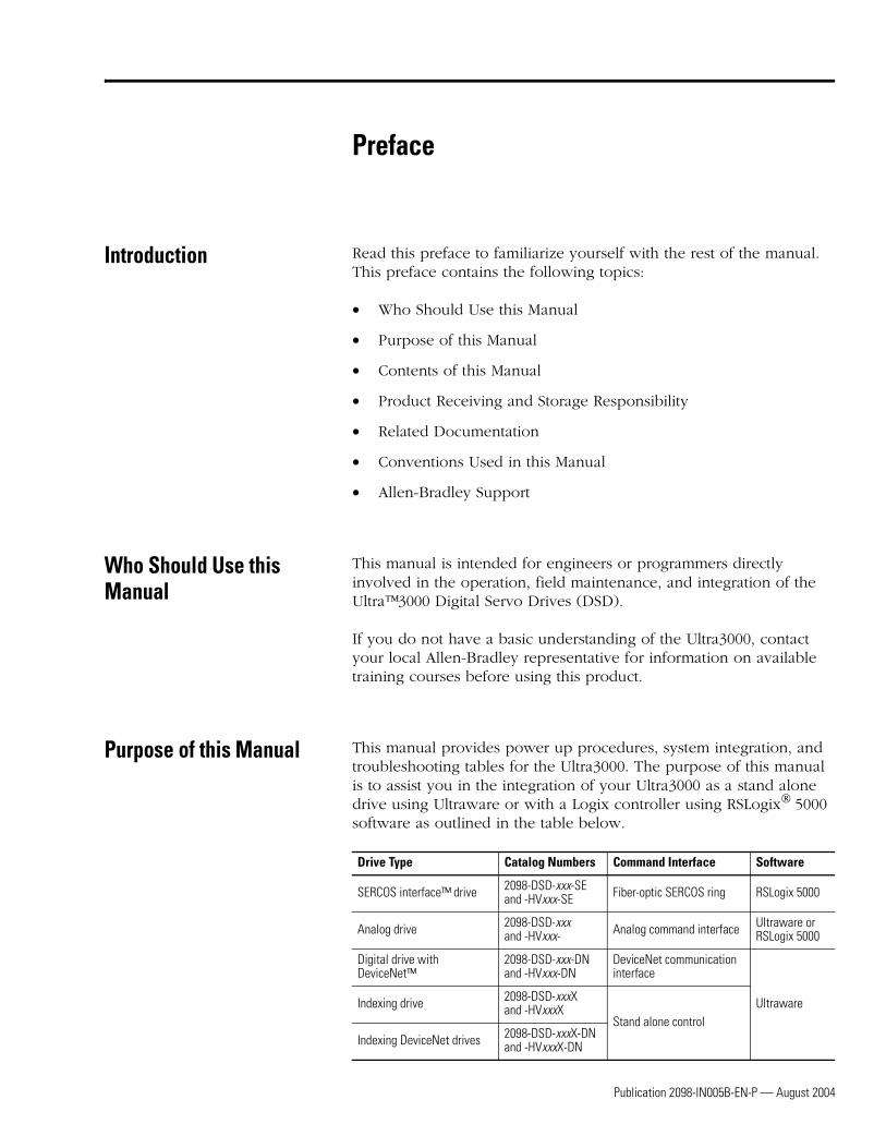
Purpose of this Manual This manual provides power up procedures, system integration, and troubleshooting tables for the Ultra3000. The purpose of this manual is to assist you in the integration of your Ultra3000 as a stand alone drive using Ultraware or with a Logix controller using RSLogix 5000 software as outlined in the table below.
Drive Type Catalog Numbers Command Interface Software
SERCOS interface™ drive 2098-DSD-xxx-SE and -HVxxx-SE Fiber-optic SERCOS ring RSLogix 5000
Analog drive 2098-DSD-xxx and -HVxxx- Analog command interface Ultraware or
RSLogix 5000
Digital drive with DeviceNet™
2098-DSD-xxx-DN and -HVxxx-DN
DeviceNet communication interface
UltrawareIndexing drive 2098-DSD-xxxX and -HVxxxX
Stand alone controlIndexing DeviceNet drives 2098-DSD-xxxX-DN
and -HVxxxX-DN
Publication 2098-IN005B-EN-P — August 2004
P-2 Preface
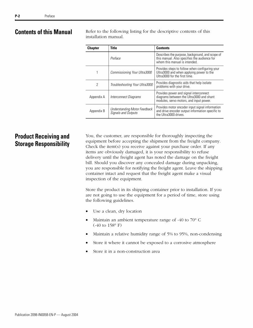
Contents of this Manual Refer to the following listing for the descriptive contents of this installation manual.
Product Receiving and Storage Responsibility
You, the customer, are responsible for thoroughly inspecting the equipment before accepting the shipment from the freight company. Check the item(s) you receive against your purchase order. If any items are obviously damaged, it is your responsibility to refuse delivery until the freight agent has noted the damage on the freight bill. Should you discover any concealed damage during unpacking, you are responsible for notifying the freight agent. Leave the shipping container intact and request that the freight agent make a visual inspection of the equipment.
Store the product in its shipping container prior to installation. If you are not going to use the equipment for a period of time, store using the following guidelines.
• Use a clean, dry location
• Maintain an ambient temperature range of -40 to 70° C (-40 to 158° F)
• Maintain a relative humidity range of 5% to 95%, non-condensing
• Store it where it cannot be exposed to a corrosive atmosphere
• Store it in a non-construction area
Chapter Title Contents
PrefaceDescribes the purpose, background, and scope of this manual. Also specifies the audience for whom this manual is intended.
1 Commissioning Your Ultra3000Provides steps to follow when configuring your Ultra3000 and when applying power to the Ultra3000 for the first time.
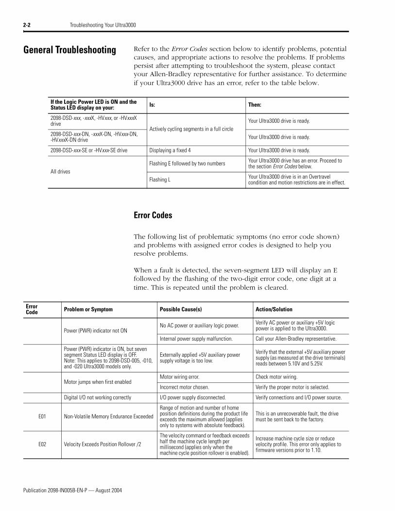
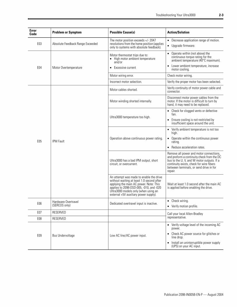
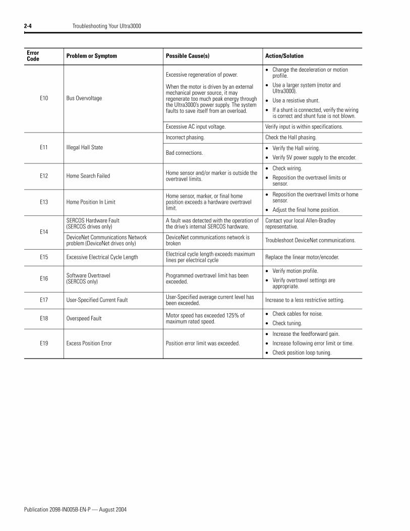
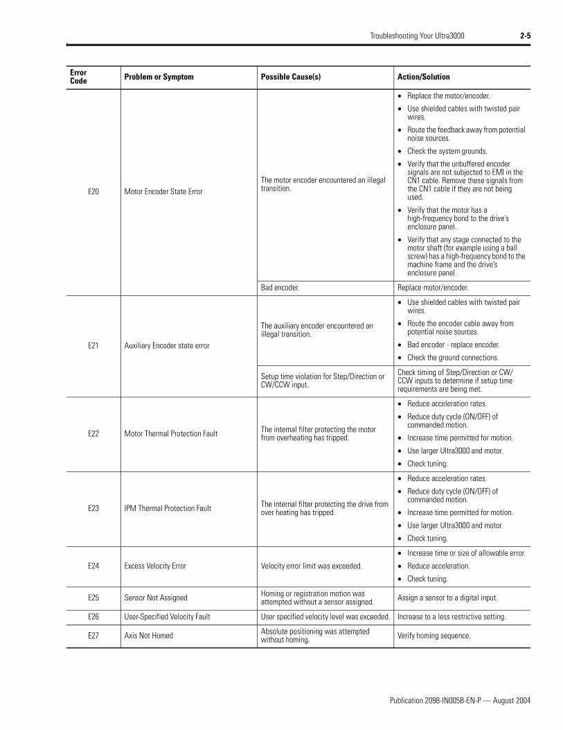
2 Troubleshooting Your Ultra3000 Provides diagnostic aids that help isolate problems with your drive.
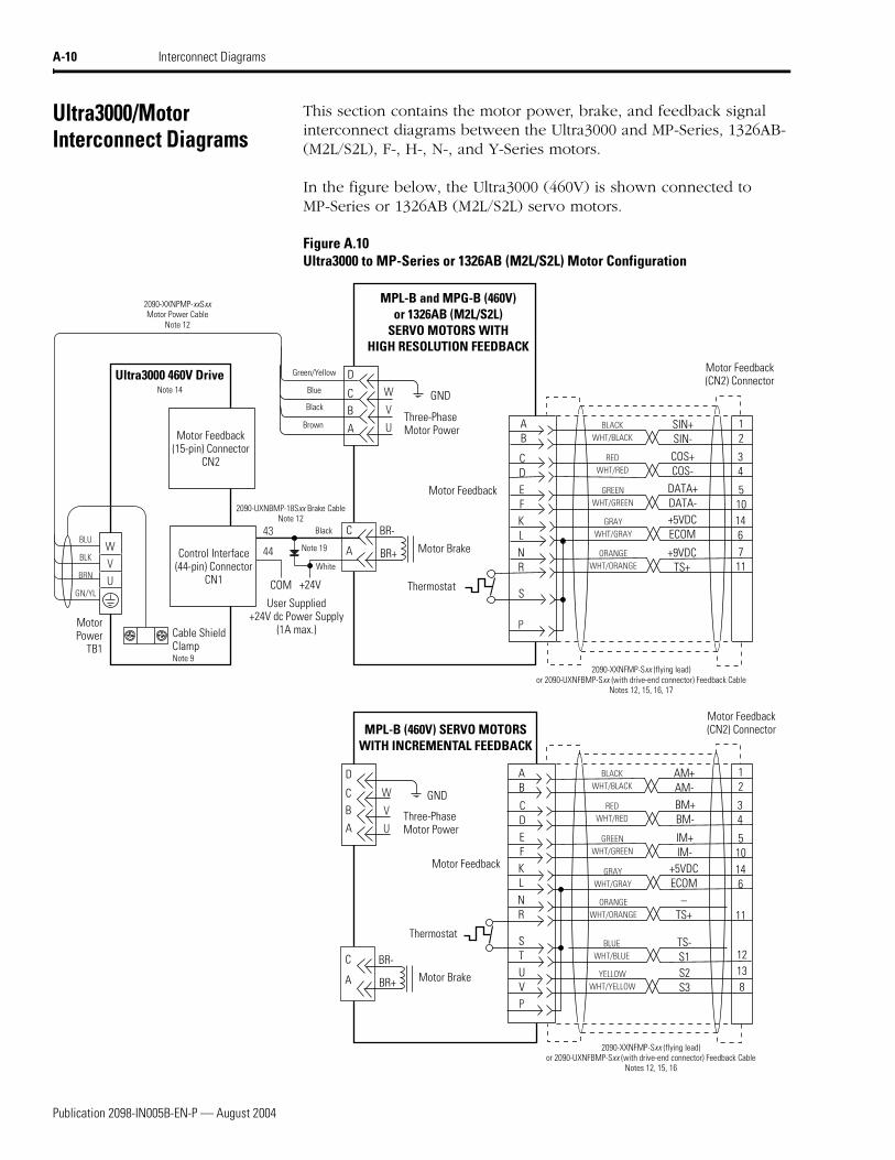
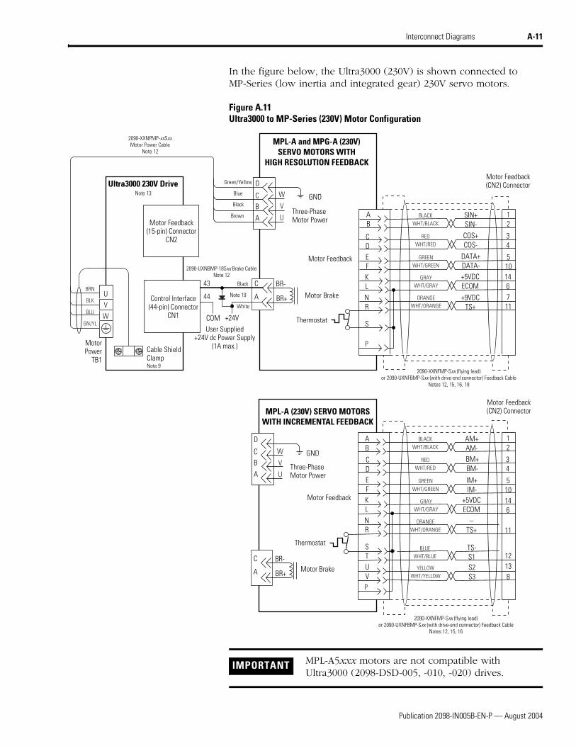
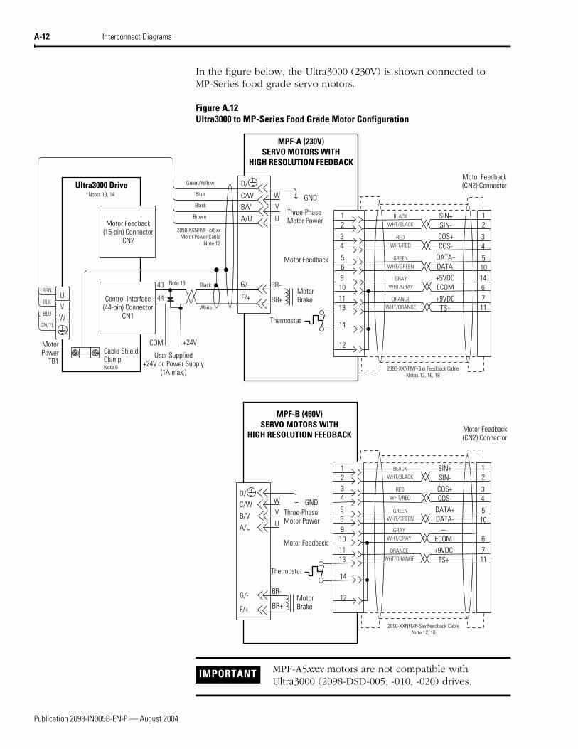
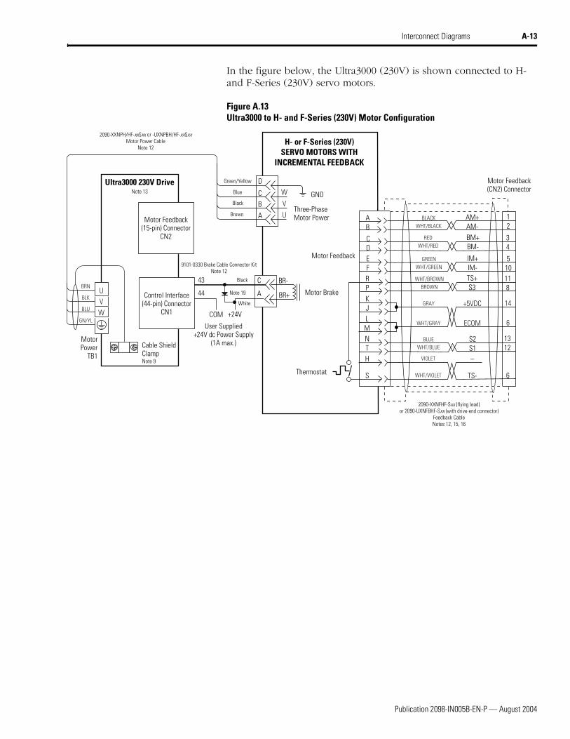
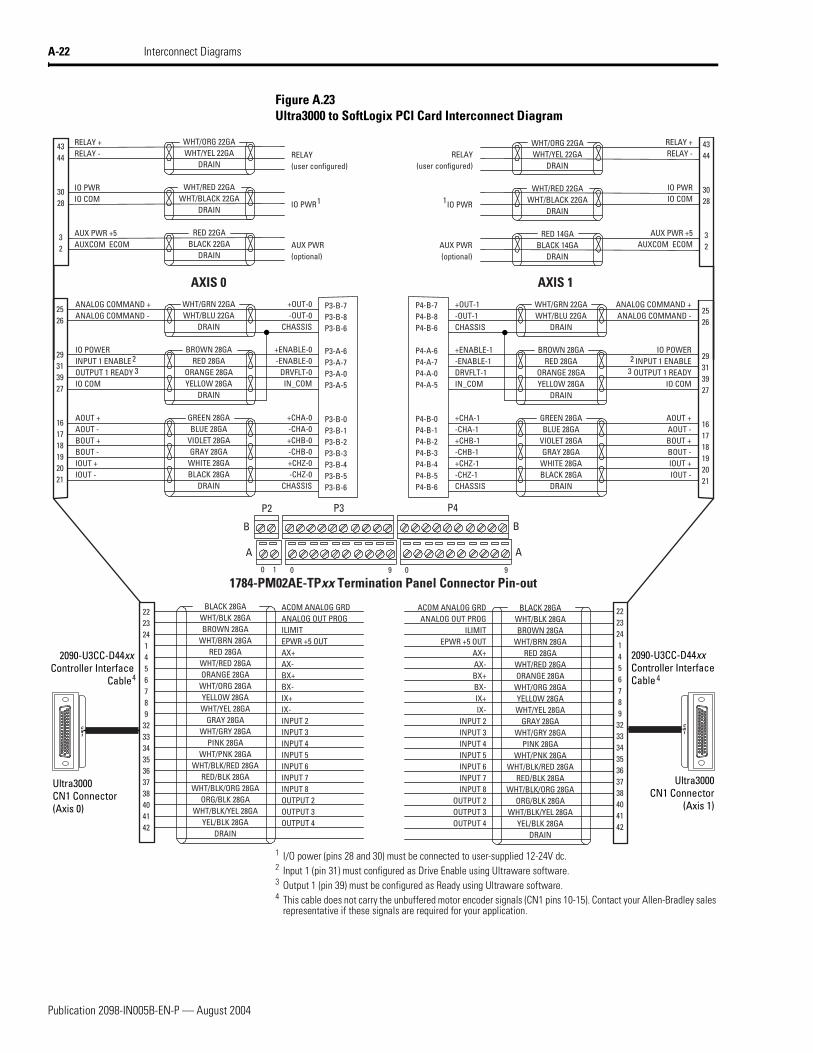
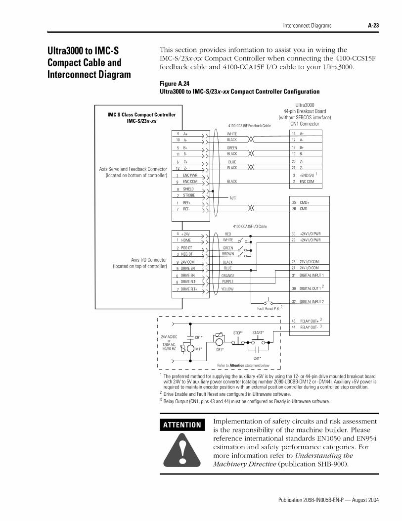
Appendix A Interconnect DiagramsProvides power and signal interconnect diagrams between the Ultra3000 and shunt modules, servo motors, and input power.
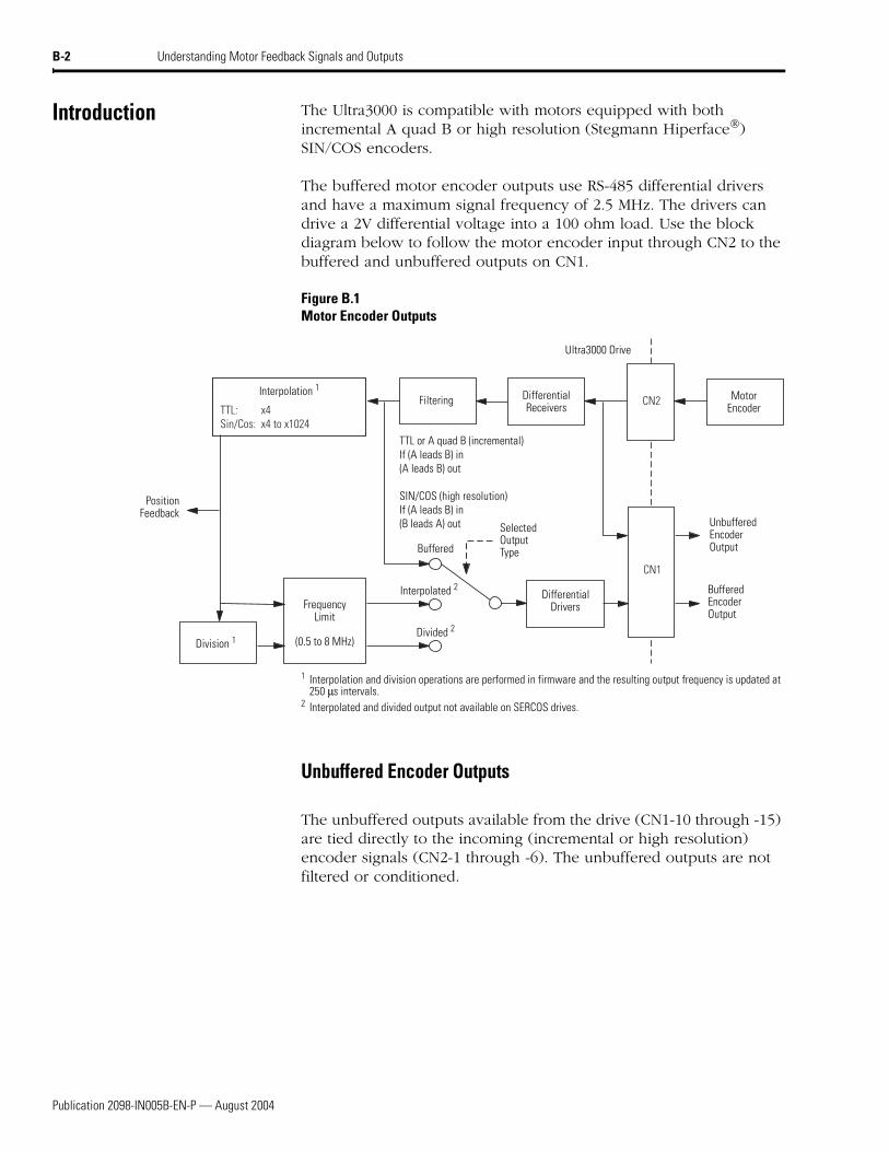
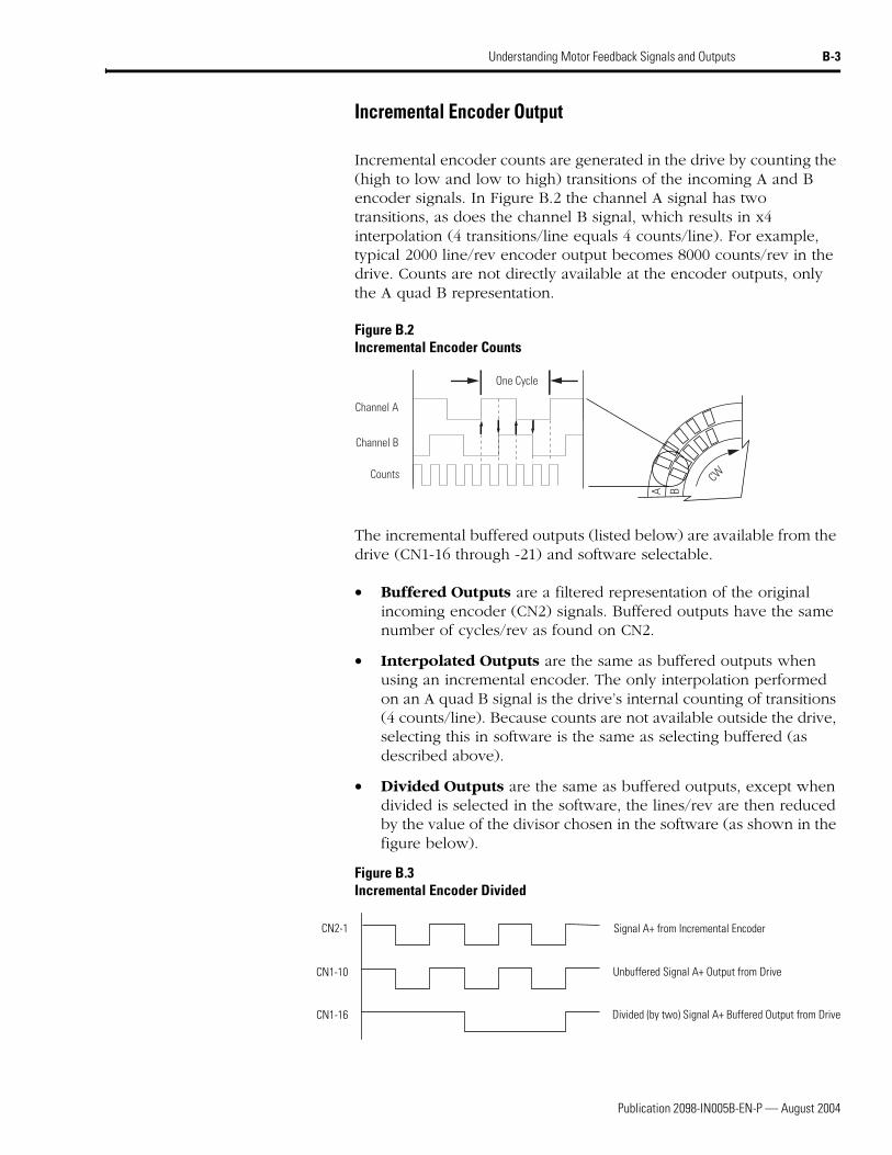
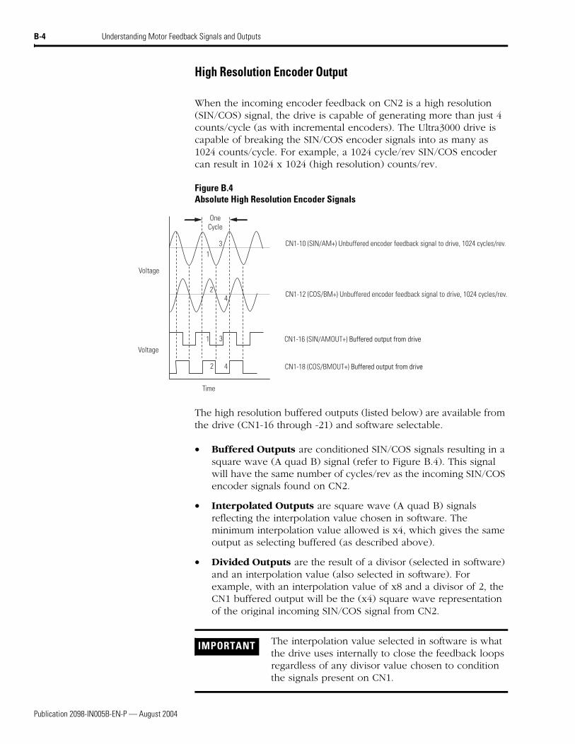
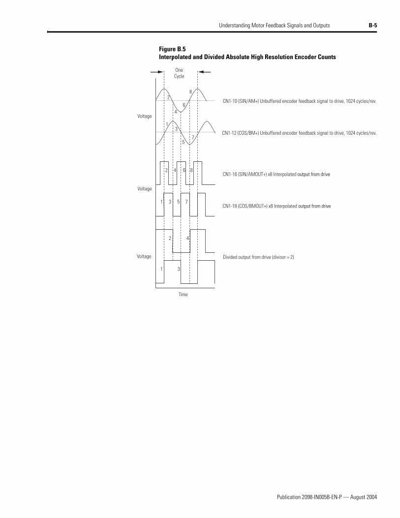
Appendix B Understanding Motor Feedback Signals and Outputs
Provides motor encoder input signal information and drive encoder output information specific to the Ultra3000 drives.
Publication 2098-IN005B-EN-P — August 2004
Preface P-3
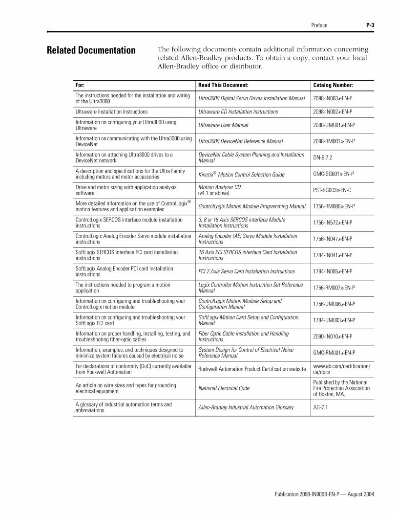
Related Documentation The following documents contain additional information concerning related Allen-Bradley products. To obtain a copy, contact your local Allen-Bradley office or distributor.
For: Read This Document: Catalog Number:
The instructions needed for the installation and wiring of the Ultra3000 Ultra3000 Digital Servo Drives Installation Manual 2098-IN003x-EN-P
Ultraware Installation Instructions Ultraware CD Installation Instructions 2098-IN002x-EN-P
Information on configuring your Ultra3000 using Ultraware Ultraware User Manual 2098-UM001x-EN-P
Information on communicating with the Ultra3000 using DeviceNet Ultra3000 DeviceNet Reference Manual 2098-RM001x-EN-P
Information on attaching Ultra3000 drives to a DeviceNet network
DeviceNet Cable System Planning and Installation Manual DN-6.7.2
A description and specifications for the Ultra Family including motors and motor accessories Kinetix Motion Control Selection Guide GMC-SG001x-EN-P
Drive and motor sizing with application analysis software
Motion Analyzer CD (v4.1 or above) PST-SG003x-EN-C
More detailed information on the use of ControlLogix motion features and application examples ControlLogix Motion Module Programming Manual 1756-RM086x-EN-P
The instructions needed to program a motion application
Logix Controller Motion Instruction Set Reference Manual 1756-RM007x-EN-P
Information on configuring and troubleshooting your ControlLogix motion module
ControlLogix Motion Module Setup and Configuration Manual 1756-UM006x-EN-P
Information on configuring and troubleshooting your SoftLogix PCI card
SoftLogix Motion Card Setup and Configuration Manual 1784-UM003x-EN-P
Information on proper handling, installing, testing, and troubleshooting fiber-optic cables
Fiber Optic Cable Installation and Handling Instructions 2090-IN010x-EN-P
Information, examples, and techniques designed to minimize system failures caused by electrical noise
System Design for Control of Electrical Noise Reference Manual GMC-RM001x-EN-P
For declarations of conformity (DoC) currently available from Rockwell Automation Rockwell Automation Product Certification website www.ab.com/certification/
ce/docs
An article on wire sizes and types for grounding electrical equipment National Electrical Code
Published by the National Fire Protection Association of Boston, MA.
A glossary of industrial automation terms and abbreviations Allen-Bradley Industrial Automation Glossary AG-7.1
Publication 2098-IN005B-EN-P — August 2004
P-4 Preface
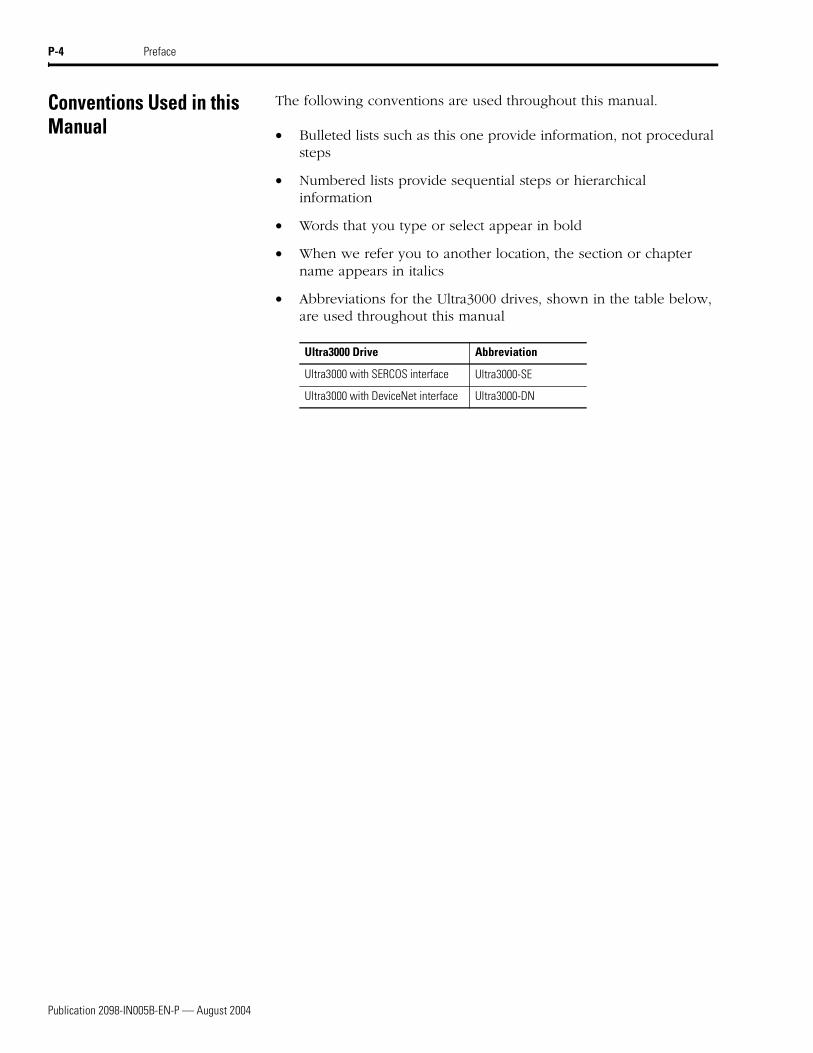
Conventions Used in this Manual
The following conventions are used throughout this manual.
• Bulleted lists such as this one provide information, not procedural steps
• Numbered lists provide sequential steps or hierarchical information
• Words that you type or select appear in bold
• When we refer you to another location, the section or chapter name appears in italics
• Abbreviations for the Ultra3000 drives, shown in the table below, are used throughout this manual
Ultra3000 Drive Abbreviation
Ultra3000 with SERCOS interface Ultra3000-SE
Ultra3000 with DeviceNet interface Ultra3000-DN
Publication 2098-IN005B-EN-P — August 2004
Preface P-5
Allen-Bradley Support Allen-Bradley offers support services worldwide, with over 75 Sales/Support Offices, 512 authorized Distributors and 260 authorized Systems Integrators located throughout the United States alone, plus Allen-Bradley representatives in every major country in the world.
Local Product Support
Contact your local Allen-Bradley representative for:
• Sales and order support
• Product technical training
• Warranty support
• Support service agreements
Technical Product Assistance
If you need to contact Allen-Bradley for technical assistance, please review the information in the chapter Troubleshooting Status Indicators first, then call your local Allen-Bradley representative or Rockwell Automation Technical Support at (440)-646-5800. For the quickest possible response, please have the catalog numbers of your products available when you call.
Comments Regarding this Manual
To offer comments regarding the contents of this manual, go to www.ab.com/manuals/gmc and download the Motion Control Problem Report form. Mail or fax your comments to the address/fax number given on the form.
Publication 2098-IN005B-EN-P — August 2004
P-6 Preface
1 Publication 2098-IN005B-EN-P — August 2004
Chapter 1
Commissioning Your Ultra3000
Chapter Objectives This chapter provides you with information to apply power and configure your Ultra3000. This chapter includes these sections:
• General Startup Precautions
• Before You Begin
• Configuring Your Ultra3000 and Ultra3000 with Indexing
• Configuring Your Ultra3000 with SERCOS interface Drive
• Configuring Your Ultra3000 with DeviceNet Drive
Note: Some of the procedures in this chapter include information regarding integration with other products.
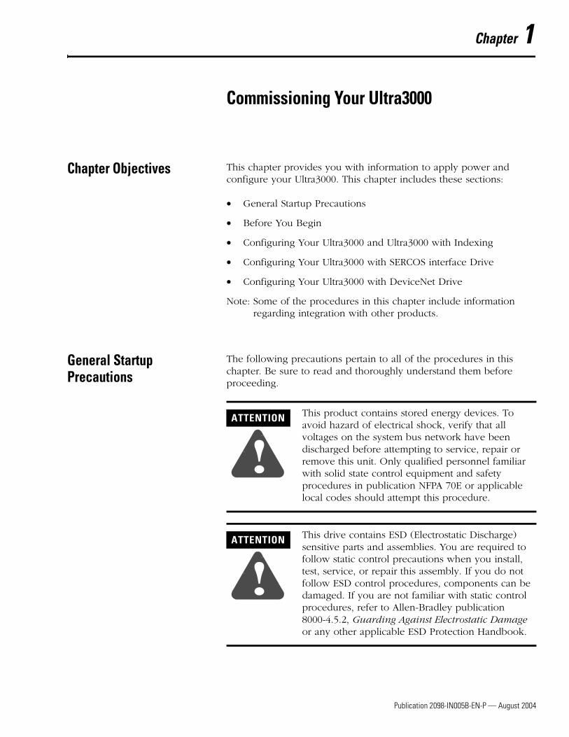
General Startup Precautions
The following precautions pertain to all of the procedures in this chapter. Be sure to read and thoroughly understand them before proceeding.
ATTENTION
!This product contains stored energy devices. To avoid hazard of electrical shock, verify that all voltages on the system bus network have been discharged before attempting to service, repair or remove this unit. Only qualified personnel familiar with solid state control equipment and safety procedures in publication NFPA 70E or applicable local codes should attempt this procedure.
ATTENTION
!This drive contains ESD (Electrostatic Discharge) sensitive parts and assemblies. You are required to follow static control precautions when you install, test, service, or repair this assembly. If you do not follow ESD control procedures, components can be damaged. If you are not familiar with static control procedures, refer to Allen-Bradley publication 8000-4.5.2, Guarding Against Electrostatic Damage or any other applicable ESD Protection Handbook.
Publication 2098-IN005B-EN-P — August 2004
1-2 Commissioning Your Ultra3000
Before You Begin These procedures assume you have completed mounting, wiring, and connecting your Ultra3000 drive as described in the Ultra3000 Digital Servo Drives Installation Manual (publication 2098-IN003x-EN-P).
Use the table below to determine where to begin configuring your Ultra3000 drive.
Configuring Your Ultra3000 and Ultra3000 with Indexing
The procedures in this section apply to Ultra3000 drives (2098-DSD-xxx, -xxxX, -HVxxx, or -HVxxxX) and describe how to:
• Apply power to your Ultra3000 drive
• Detect your Ultra3000 drive
• Understand the workspace and drive branches in Ultraware
• Select your motor
• Tune your motor
• Test your motor (non-indexing move)
• Test your motor (indexing move)
• Make indexing and non-indexing moves
• Configure your Ultra3000 drive with the Logix servo module
If you are configuring this drive: Then:
2098-DSD-xxx, -xxxX, -HVxxx, or -HVxxxX Go to Configuring Your Ultra3000 and Ultra3000 with Indexing
2098-DSD-xxx-SE or -HVxxx-SE Go to Configuring Your Ultra3000 Drive
2098-DSD-xxx-DN, -xxxX-DN, -HVxxx-DN, or -HVxxxX-DN
Go to Configuring Your Ultra3000 with DeviceNet Drive
Publication 2098-IN005B-EN-P — August 2004
Commissioning Your Ultra3000 1-3
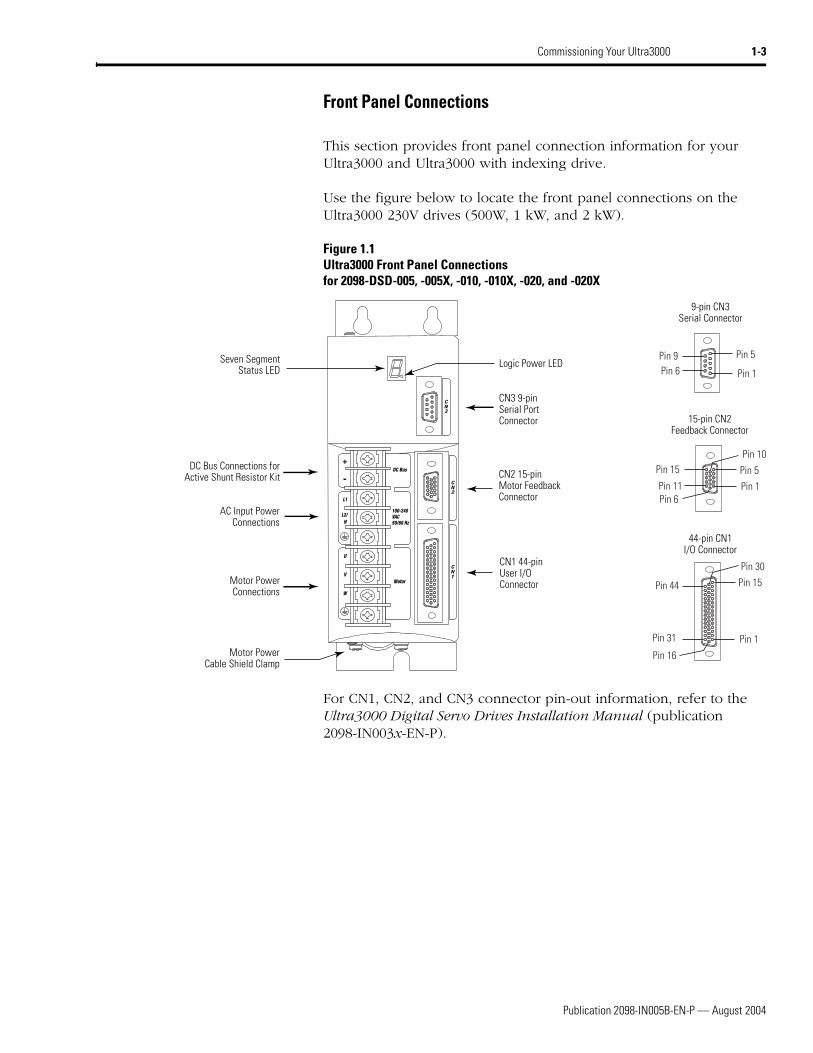
Front Panel Connections
This section provides front panel connection information for your Ultra3000 and Ultra3000 with indexing drive.
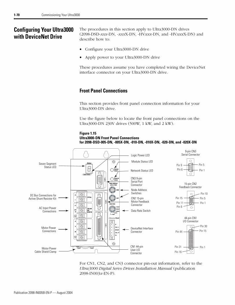
Use the figure below to locate the front panel connections on the Ultra3000 230V drives (500W, 1 kW, and 2 kW).
Figure 1.1Ultra3000 Front Panel Connections for 2098-DSD-005, -005X, -010, -010X, -020, and -020X
For CN1, CN2, and CN3 connector pin-out information, refer to the Ultra3000 Digital Servo Drives Installation Manual (publication 2098-IN003x-EN-P).
Pin 11Pin 6
Pin 15
Pin 1
Pin 10
Pin 5
Pin 30
Pin 44
Pin 1
Pin 15
Pin 16
Pin 31
Pin 6Pin 9
Pin 1
Pin 5
CN1 44-pinUser I/OConnector
CN2 15-pinMotor FeedbackConnector
CN3 9-pinSerial PortConnector
Logic Power LEDSeven SegmentStatus LED
DC Bus Connections forActive Shunt Resistor Kit
AC Input Power Connections
Motor Power Connections
9-pin CN3Serial Connector
15-pin CN2Feedback Connector
44-pin CN1I/O Connector
Motor Power Cable Shield Clamp
Publication 2098-IN005B-EN-P — August 2004
1-4 Commissioning Your Ultra3000
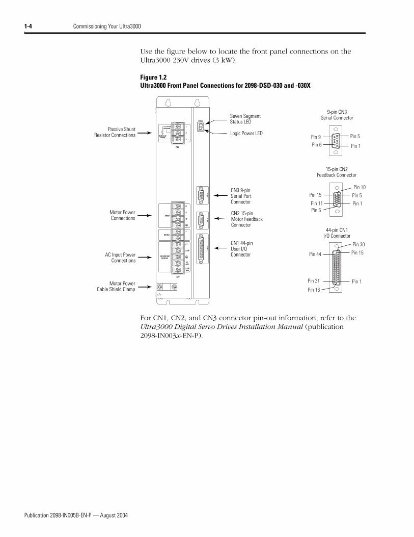
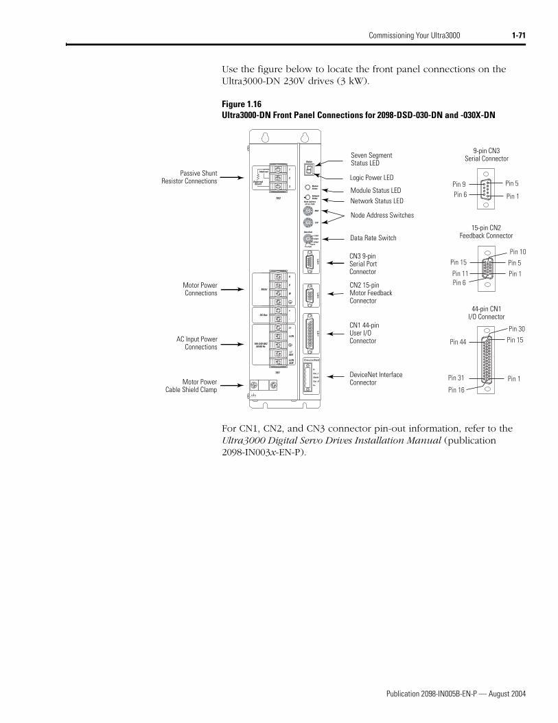
Use the figure below to locate the front panel connections on the Ultra3000 230V drives (3 kW).
Figure 1.2Ultra3000 Front Panel Connections for 2098-DSD-030 and -030X
For CN1, CN2, and CN3 connector pin-out information, refer to the Ultra3000 Digital Servo Drives Installation Manual (publication 2098-IN003x-EN-P).
U
V
W
+
-
L1
L2/N
L1AUX
L2/NAUX
1
2
3
Motor
DC Bus
100-240 VAC50/60 Hz
Internal
ExternalShunt
TB1
TB2
Pin 11Pin 6
Pin 15
Pin 1
Pin 10
Pin 5
Pin 30
Pin 44
Pin 1
Pin 15
Pin 16
Pin 31
Pin 6Pin 9
Pin 1
Pin 5
AC Input Power Connections
Motor Power Connections
Passive Shunt Resistor Connections
Seven Segment Status LED
Logic Power LED
CN3 9-pin Serial Port Connector
CN2 15-pin Motor Feedback Connector
CN1 44-pin User I/O Connector
Motor Power Cable Shield Clamp
9-pin CN3Serial Connector
15-pin CN2Feedback Connector
44-pin CN1I/O Connector
Publication 2098-IN005B-EN-P — August 2004
Commissioning Your Ultra3000 1-5
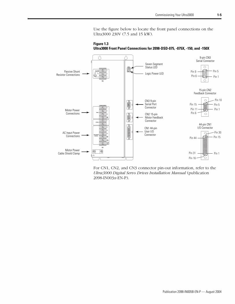
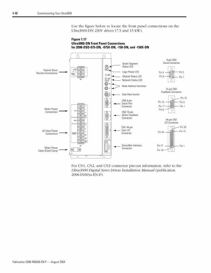
Use the figure below to locate the front panel connections on the Ultra3000 230V (7.5 and 15 kW).
Figure 1.3Ultra3000 Front Panel Connections for 2098-DSD-075, -075X, -150, and -150X
For CN1, CN2, and CN3 connector pin-out information, refer to the Ultra3000 Digital Servo Drives Installation Manual (publication 2098-IN003x-EN-P).
U
V
W
+
-
L1
L2
L3
L1AUX
L2/NAUX
Motor
DC Bus
100-240 VAC50/60 Hz
Internal
ExternalShunt
1
2
3
TB2
TB1
Pin 11Pin 6
Pin 15
Pin 1
Pin 10
Pin 5
Pin 30
Pin 44
Pin 1
Pin 15
Pin 16
Pin 31
Pin 6Pin 9
Pin 1
Pin 5
AC Input Power Connections
Motor Power Connections
Passive Shunt Resistor Connections
Seven Segment Status LED
Logic Power LED
CN3 9-pin Serial Port Connector
CN2 15-pin Motor Feedback Connector
CN1 44-pin User I/O Connector
Motor Power Cable Shield Clamp
9-pin CN3Serial Connector
15-pin CN2Feedback Connector
44-pin CN1I/O Connector
Publication 2098-IN005B-EN-P — August 2004
1-6 Commissioning Your Ultra3000
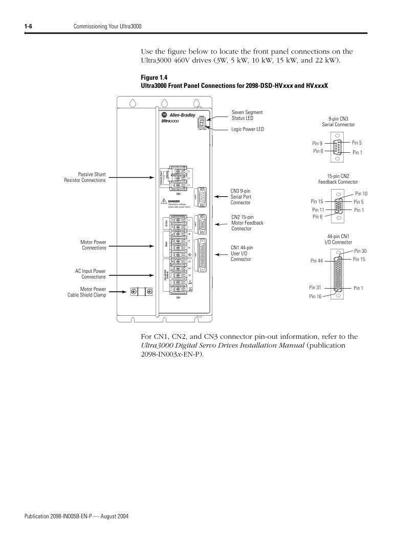
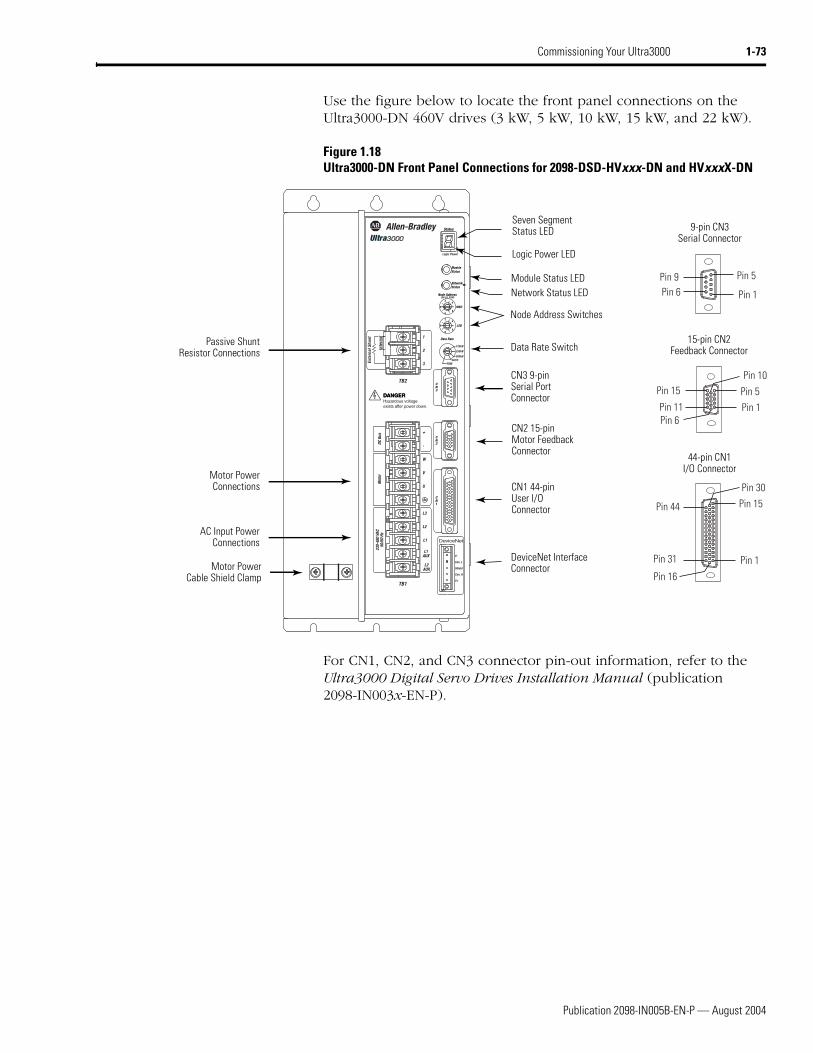
Use the figure below to locate the front panel connections on the Ultra3000 460V drives (3W, 5 kW, 10 kW, 15 kW, and 22 kW).
Figure 1.4Ultra3000 Front Panel Connections for 2098-DSD-HVxxx and HVxxxX
For CN1, CN2, and CN3 connector pin-out information, refer to the Ultra3000 Digital Servo Drives Installation Manual (publication 2098-IN003x-EN-P).
W
V
U
+
-
L3
L2
L1
L1AUX
L2AUX
Mot
orDC
Bus
230-
480
VAC
50/6
0 Hz
Inte
rnal
Exte
rnal
Shu
nt 1
2
3
TB2
DANGERDANGERHazardous voltageexists after power down.
TB1
Pin 11Pin 6
Pin 15
Pin 1
Pin 10
Pin 5
Pin 30
Pin 44
Pin 1
Pin 15
Pin 16
Pin 31
Pin 6Pin 9
Pin 1
Pin 5
AC Input Power Connections
Motor Power Connections
Passive Shunt Resistor Connections
Seven Segment Status LED
Logic Power LED
CN3 9-pin Serial Port Connector
CN2 15-pin Motor Feedback Connector
CN1 44-pin User I/O Connector
Motor Power Cable Shield Clamp
9-pin CN3Serial Connector
15-pin CN2Feedback Connector
44-pin CN1I/O Connector
Publication 2098-IN005B-EN-P — August 2004
Commissioning Your Ultra3000 1-7
Applying Power To Your Ultra3000 Drive
This procedure assumes you have wired your Ultra3000 system, verified the wiring, and are ready to begin using your Ultraware software.
To apply power to your Ultra3000 drive:
1. Disconnect any load to the motor. Ensure the motor is free of all linkages when initially applying power to the system.
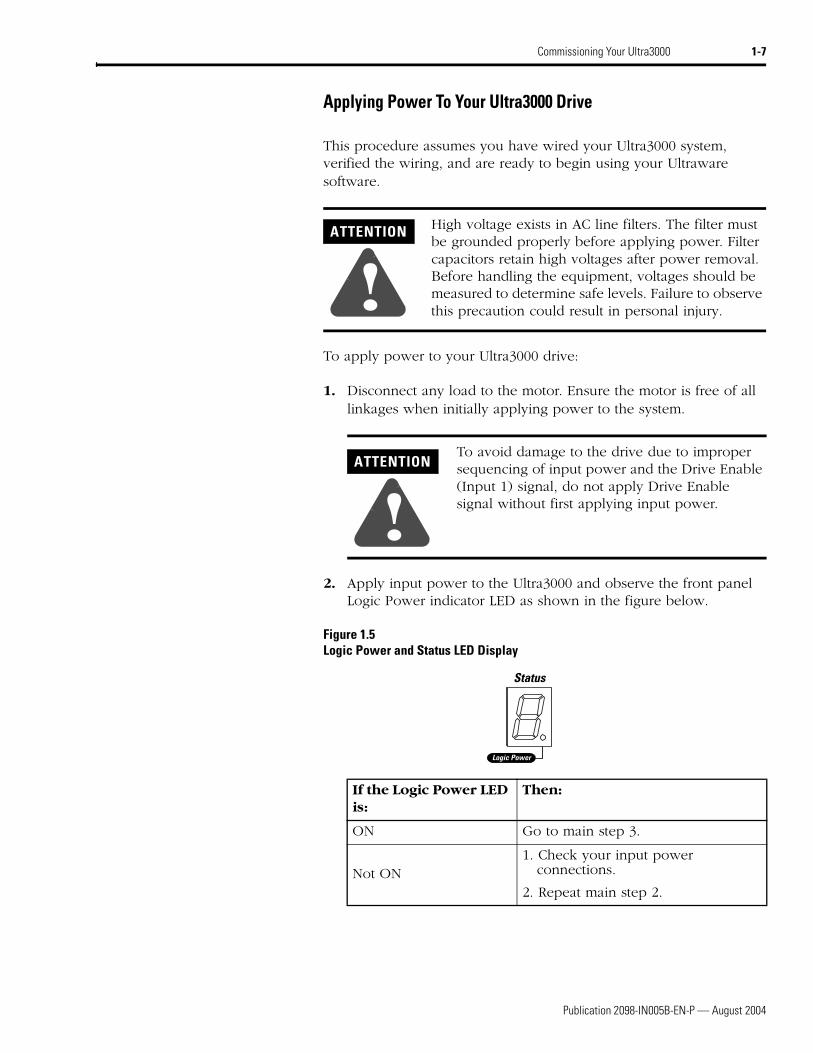
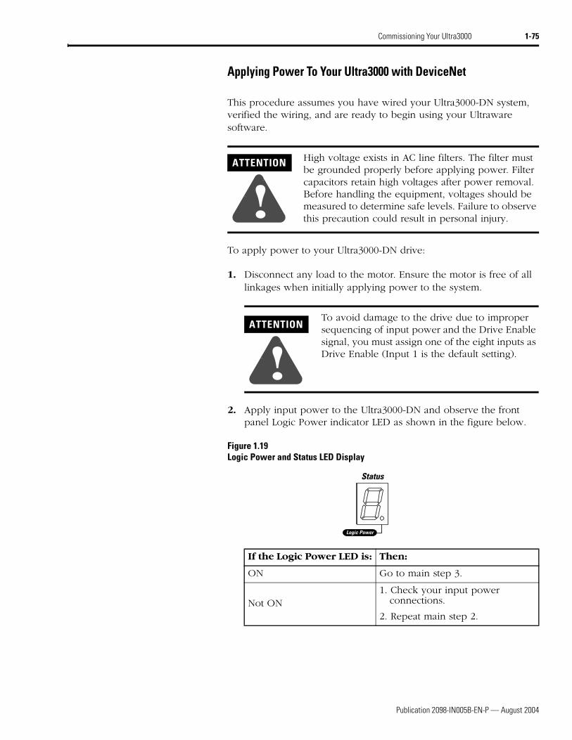
2. Apply input power to the Ultra3000 and observe the front panel Logic Power indicator LED as shown in the figure below.
Figure 1.5Logic Power and Status LED Display
ATTENTION
!High voltage exists in AC line filters. The filter must be grounded properly before applying power. Filter capacitors retain high voltages after power removal. Before handling the equipment, voltages should be measured to determine safe levels. Failure to observe this precaution could result in personal injury.
ATTENTION
!To avoid damage to the drive due to improper sequencing of input power and the Drive Enable (Input 1) signal, do not apply Drive Enable signal without first applying input power.
Status
Logic Power
If the Logic Power LED is:
Then:
ON Go to main step 3.
Not ON1. Check your input power
connections.
2. Repeat main step 2.
Publication 2098-IN005B-EN-P — August 2004
1-8 Commissioning Your Ultra3000
3. Observe the front panel seven segment Status LED display as shown in Figure 1.5.
Detecting Your Ultra3000 Drive
This procedure assumes you have successfully applied power to your drive. By following these steps you will ensure that your Ultra3000 drive is communicating with your Ultraware software. To detect your Ultra3000 drive:
1. Start your Ultraware software. Refer to the Ultraware User Manual (publication 2098-UM001x-EN-P) for more information on starting the Ultraware software.
2. Create a new file. Ultraware will scan for on-line drives.
3. Click on the Stop Scanning button when your drive is detected or wait for the scanning to time out.
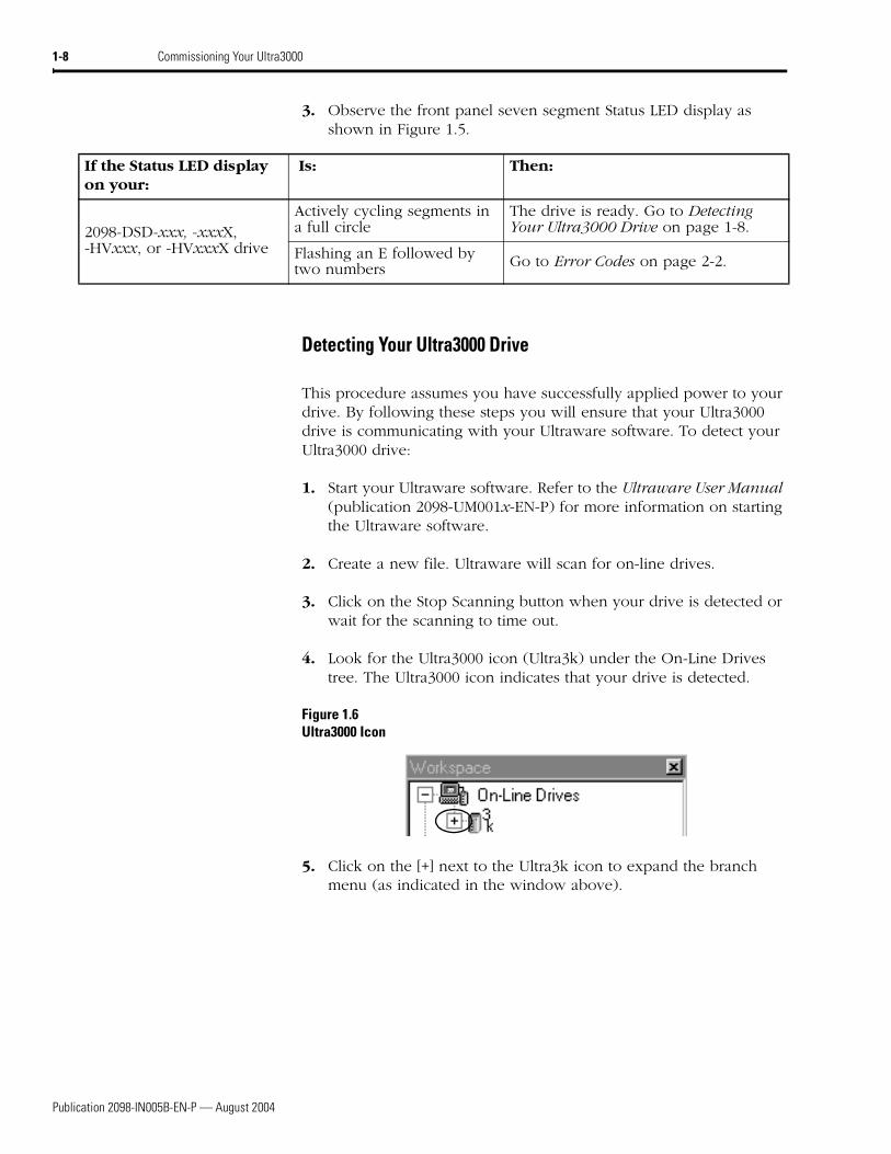
4. Look for the Ultra3000 icon (Ultra3k) under the On-Line Drives tree. The Ultra3000 icon indicates that your drive is detected.
Figure 1.6Ultra3000 Icon
5. Click on the [+] next to the Ultra3k icon to expand the branch menu (as indicated in the window above).
If the Status LED display on your:
Is: Then:
2098-DSD-xxx, -xxxX, -HVxxx, or -HVxxxX drive
Actively cycling segments in a full circle
The drive is ready. Go to Detecting Your Ultra3000 Drive on page 1-8.
Flashing an E followed by two numbers Go to Error Codes on page 2-2.
Publication 2098-IN005B-EN-P — August 2004
Commissioning Your Ultra3000 1-9
6.
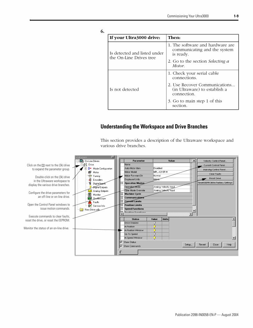
Understanding the Workspace and Drive Branches
This section provides a description of the Ultraware workspace and various drive branches.
If your Ultra3000 drive: Then:
Is detected and listed under the On-Line Drives tree
1. The software and hardware are communicating and the system is ready.
2. Go to the section Selecting a Motor.
Is not detected
1. Check your serial cable connections.
2. Use Recover Communications... (in Ultraware) to establish a connection.
3. Go to main step 1 of this section.
Click on the + next to the (3k) driveto expand the parameter group.
Double-click on the (3k) drivein the Ultraware workspace to
display the various drive branches.
Configure the drive parameters foran off-line or on-line drive.
Open the Control Panel windows toissue motion commands.
Execute commands to clear faults,reset the drive, or reset the EEPROM.
Monitor the status of an on-line drive.
Publication 2098-IN005B-EN-P — August 2004
1-10 Commissioning Your Ultra3000
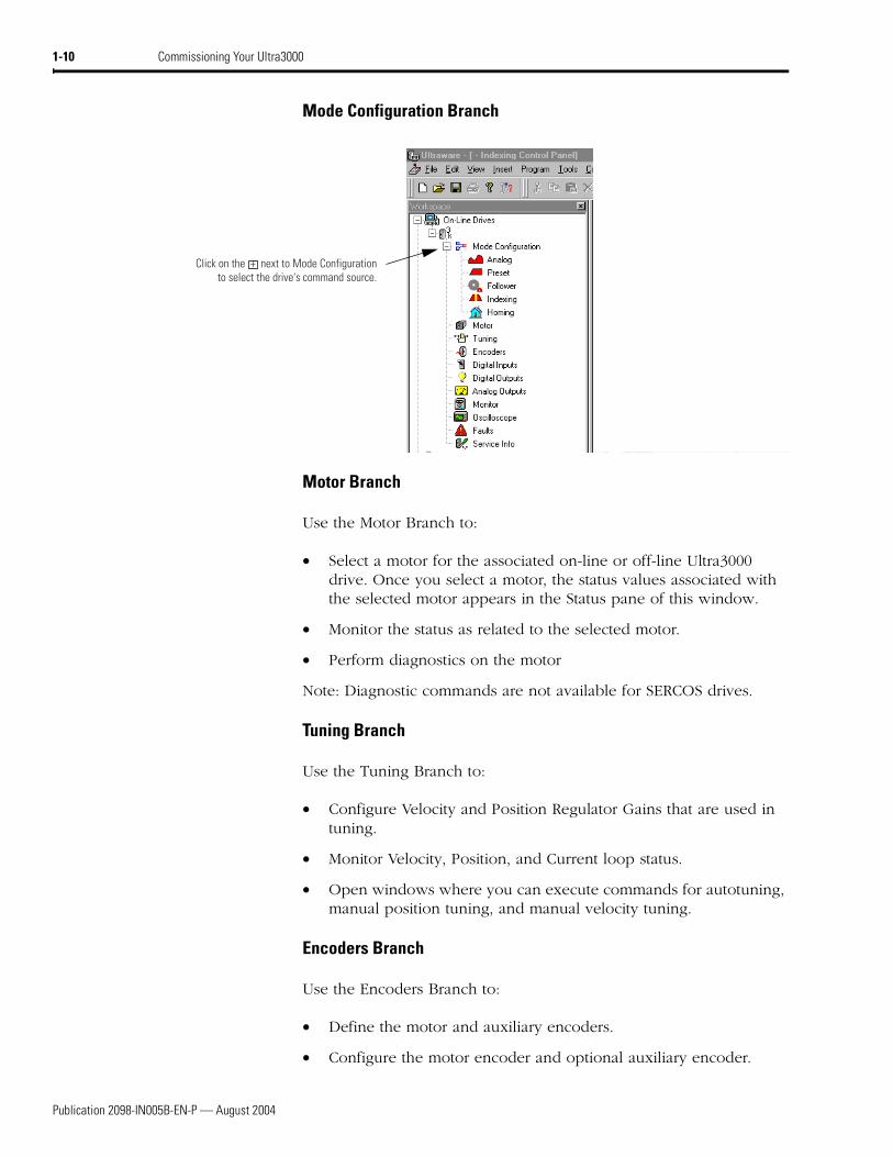
Mode Configuration Branch
Motor Branch
Use the Motor Branch to:
• Select a motor for the associated on-line or off-line Ultra3000 drive. Once you select a motor, the status values associated with the selected motor appears in the Status pane of this window.
• Monitor the status as related to the selected motor.
• Perform diagnostics on the motor
Note: Diagnostic commands are not available for SERCOS drives.
Tuning Branch
Use the Tuning Branch to:
• Configure Velocity and Position Regulator Gains that are used in tuning.
• Monitor Velocity, Position, and Current loop status.
• Open windows where you can execute commands for autotuning, manual position tuning, and manual velocity tuning.
Encoders Branch
Use the Encoders Branch to:
• Define the motor and auxiliary encoders.
• Configure the motor encoder and optional auxiliary encoder.
Click on the + next to Mode Configurationto select the drive's command source.
Publication 2098-IN005B-EN-P — August 2004
Commissioning Your Ultra3000 1-11
Digital Inputs Branch
Use the Digital Inputs Branch to:
• Assign functionality to digital inputs.
• Monitor the status of digital inputs.
Digital Outputs Branch
Use the Digital Outputs Branch to:
• Assign functionality to digital outputs.
• Set both active and inactive brake delays.
• Monitor the status of digital outputs and the digital relay.
• Open other windows where you can override the state of digital outputs and the relay.
Analog Outputs Branch
Use the Analog Outputs Branch to:
• Assign drive signals to analog outputs
• Monitor the status of Analog Outputs
• Open a window where you can monitor and override the analog output value.
Monitor Branch
Use the Monitor Branch to:
• View a collection of statuses.
• Open the Monitor Setup window where you can select the collection of statuses to display in this window.
• Load a monitor previously saved.
• Save a monitor for later use.
Publication 2098-IN005B-EN-P — August 2004
1-12 Commissioning Your Ultra3000
Oscilloscope Branch
Use the Oscilloscope Branch to trace one of four drive signals by:
• Configuring the oscilloscope by selecting a the drive signal to trace.
• Executing commands that run the oscilloscope's tracing function continuously or in response to the configured trigger.
• Monitoring the oscilloscope as it traces the selected drive signal.
Faults Branch
Use the Faults Branch to:
• Set fault limits
• Monitor fault status
• Execute the Clear Faults command
• Open a window where you can review the drive's fault history
• Enable or disable user faults.
Service Information Branch
Use the Service Information Branch to:
• Modify the size of an off-line drive file before transferring the configuration to an on-line drive.
• Display and monitor service information about the drive.
• Display the firmware version of the drive.
Publication 2098-IN005B-EN-P — August 2004
Commissioning Your Ultra3000 1-13
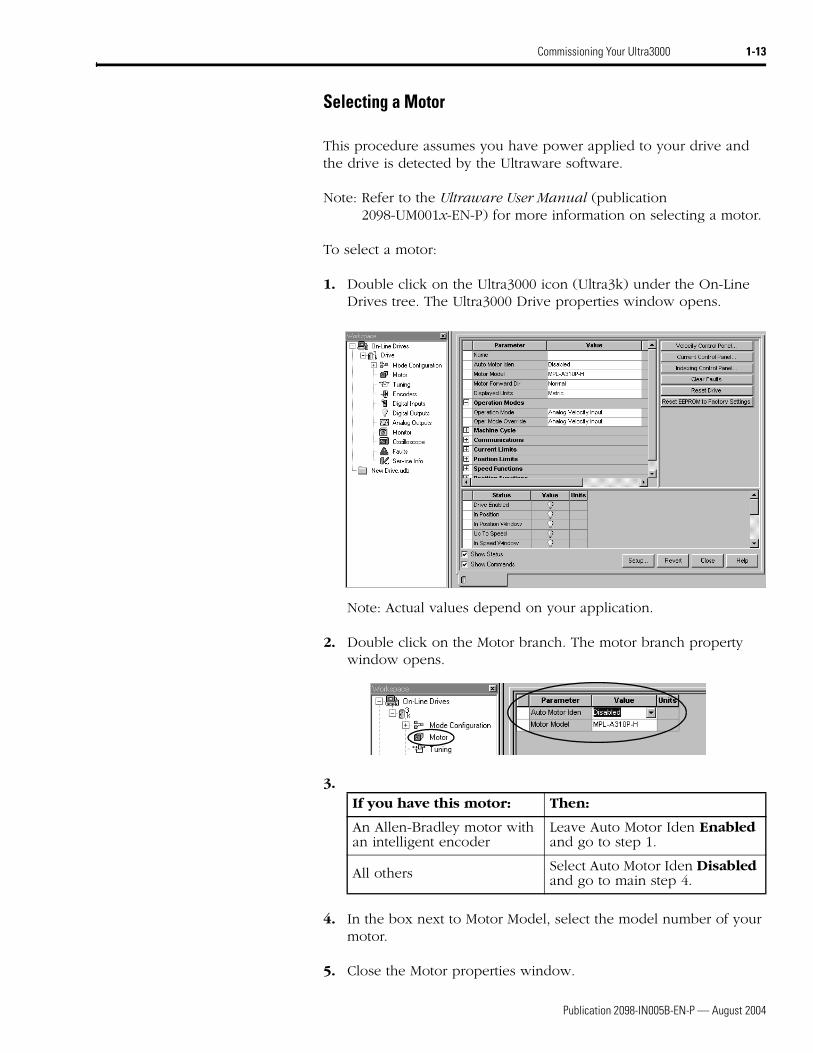
Selecting a Motor
This procedure assumes you have power applied to your drive and the drive is detected by the Ultraware software.
Note: Refer to the Ultraware User Manual (publication 2098-UM001x-EN-P) for more information on selecting a motor.
To select a motor:
1. Double click on the Ultra3000 icon (Ultra3k) under the On-Line Drives tree. The Ultra3000 Drive properties window opens.
Note: Actual values depend on your application.
2. Double click on the Motor branch. The motor branch property window opens.
3.
4. In the box next to Motor Model, select the model number of your motor.
5. Close the Motor properties window.
If you have this motor: Then:
An Allen-Bradley motor with an intelligent encoder
Leave Auto Motor Iden Enabled and go to step 1.
All others Select Auto Motor Iden Disabled and go to main step 4.
Publication 2098-IN005B-EN-P — August 2004
1-14 Commissioning Your Ultra3000
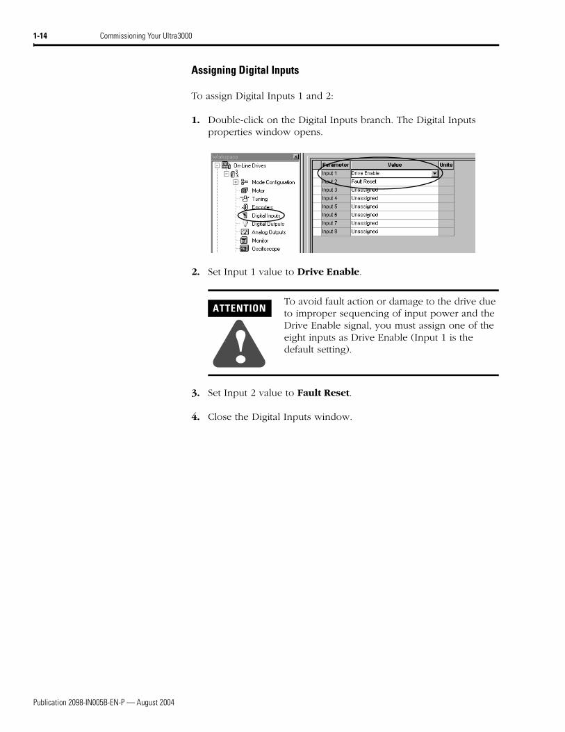
Assigning Digital Inputs
To assign Digital Inputs 1 and 2:
1. Double-click on the Digital Inputs branch. The Digital Inputs properties window opens.
2. Set Input 1 value to Drive Enable.
3. Set Input 2 value to Fault Reset.
4. Close the Digital Inputs window.
ATTENTION
!To avoid fault action or damage to the drive due to improper sequencing of input power and the Drive Enable signal, you must assign one of the eight inputs as Drive Enable (Input 1 is the default setting).
Publication 2098-IN005B-EN-P — August 2004
Commissioning Your Ultra3000 1-15
Tuning Your Motor
This procedure assumes your drive is detected and you have selected a motor. In this procedure you will autotune your motor.
To autotune your motor:
1. Double-click on the Tuning branch. The Tuning branch properties window opens.
2. Select Autotuning. The Autotuning window opens.
3. Apply 12-24V to input 1. Input 1 was configured as Drive Enable in a previous step (Drive Enabled light turns yellow).
4. Select appropriate autotune settings for your application.
5. Select Start Autotune. The motor responds and the tuning process is complete (Autotune Complete light turns yellow).
Note: Actual values depend on your application.
6. Close the Tuning properties window.
ATTENTION
!To avoid damage to the drive due to improper sequencing of input power and the Drive Enable signal, do not apply Drive Enable signal without first applying input power.
Publication 2098-IN005B-EN-P — August 2004
1-16 Commissioning Your Ultra3000
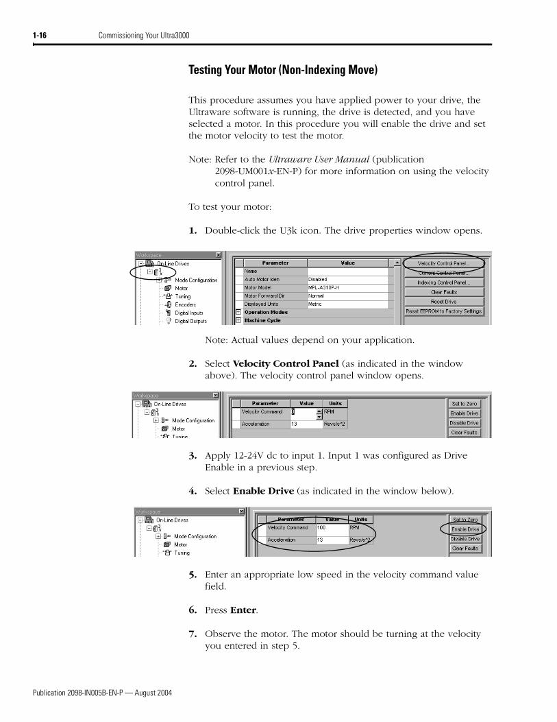
Testing Your Motor (Non-Indexing Move)
This procedure assumes you have applied power to your drive, the Ultraware software is running, the drive is detected, and you have selected a motor. In this procedure you will enable the drive and set the motor velocity to test the motor.
Note: Refer to the Ultraware User Manual (publication 2098-UM001x-EN-P) for more information on using the velocity control panel.
To test your motor:
1. Double-click the U3k icon. The drive properties window opens.
Note: Actual values depend on your application.
2. Select Velocity Control Panel (as indicated in the window above). The velocity control panel window opens.
3. Apply 12-24V dc to input 1. Input 1 was configured as Drive Enable in a previous step.
4. Select Enable Drive (as indicated in the window below).
5. Enter an appropriate low speed in the velocity command value field.
6. Press Enter.
7. Observe the motor. The motor should be turning at the velocity you entered in step 5.
Publication 2098-IN005B-EN-P — August 2004
Commissioning Your Ultra3000 1-17
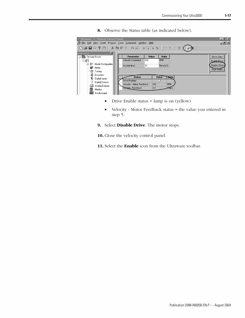
8. Observe the Status table (as indicated below).
• Drive Enable status = lamp is on (yellow)
• Velocity - Motor Feedback status = the value you entered in step 5.
9. Select Disable Drive. The motor stops.
10. Close the velocity control panel.
11. Select the Enable icon from the Ultraware toolbar.
Publication 2098-IN005B-EN-P — August 2004
1-18 Commissioning Your Ultra3000
Testing Your Motor (Indexing Move)
This procedure assumes you have applied power to your drive, the Ultraware software is running, the drive is detected, and you have selected a motor. In this procedure you will enable the drive and make an incremental move to test the motor.
Note: Refer to the Ultraware User Manual (publication 2098-UM001x-EN-P) for more information on using the indexing control panel.
To test your motor:
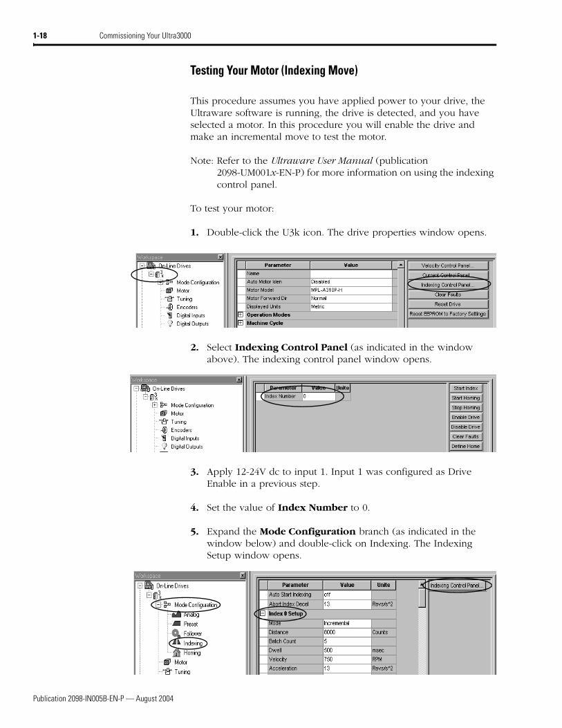
1. Double-click the U3k icon. The drive properties window opens.
2. Select Indexing Control Panel (as indicated in the window above). The indexing control panel window opens.
3. Apply 12-24V dc to input 1. Input 1 was configured as Drive Enable in a previous step.
4. Set the value of Index Number to 0.
5. Expand the Mode Configuration branch (as indicated in the window below) and double-click on Indexing. The Indexing Setup window opens.
Publication 2098-IN005B-EN-P — August 2004
Commissioning Your Ultra3000 1-19
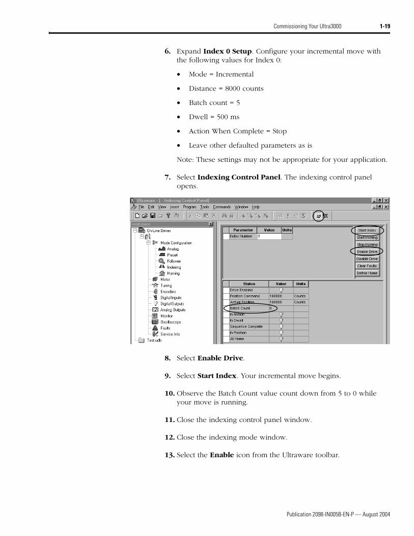
6. Expand Index 0 Setup. Configure your incremental move with the following values for Index 0:
• Mode = Incremental
• Distance = 8000 counts
• Batch count = 5
• Dwell = 500 ms
• Action When Complete = Stop
• Leave other defaulted parameters as is
Note: These settings may not be appropriate for your application.
7. Select Indexing Control Panel. The indexing control panel opens.
8. Select Enable Drive.
9. Select Start Index. Your incremental move begins.
10. Observe the Batch Count value count down from 5 to 0 while your move is running.
11. Close the indexing control panel window.
12. Close the indexing mode window.
13. Select the Enable icon from the Ultraware toolbar.
Publication 2098-IN005B-EN-P — August 2004
1-20 Commissioning Your Ultra3000
Indexing and Non-Indexing Move Examples
This section provides examples of indexing and non-indexing moves you can make with your Ultra3000 drive using Ultraware.
Analog Velocity Mode (Non-Indexing Move)
This procedure assumes you have applied power to your drive, the Ultraware software is running, the drive is detected, and you have tested a motor. In this procedure you will run the drive in analog velocity mode.
Note: Refer to the Ultraware User Manual (publication 2098-UM001x-EN-P) for more information on analog velocity mode.
To run your drive in analog velocity mode:
1. Double-click the U3k icon. The drive properties window opens.
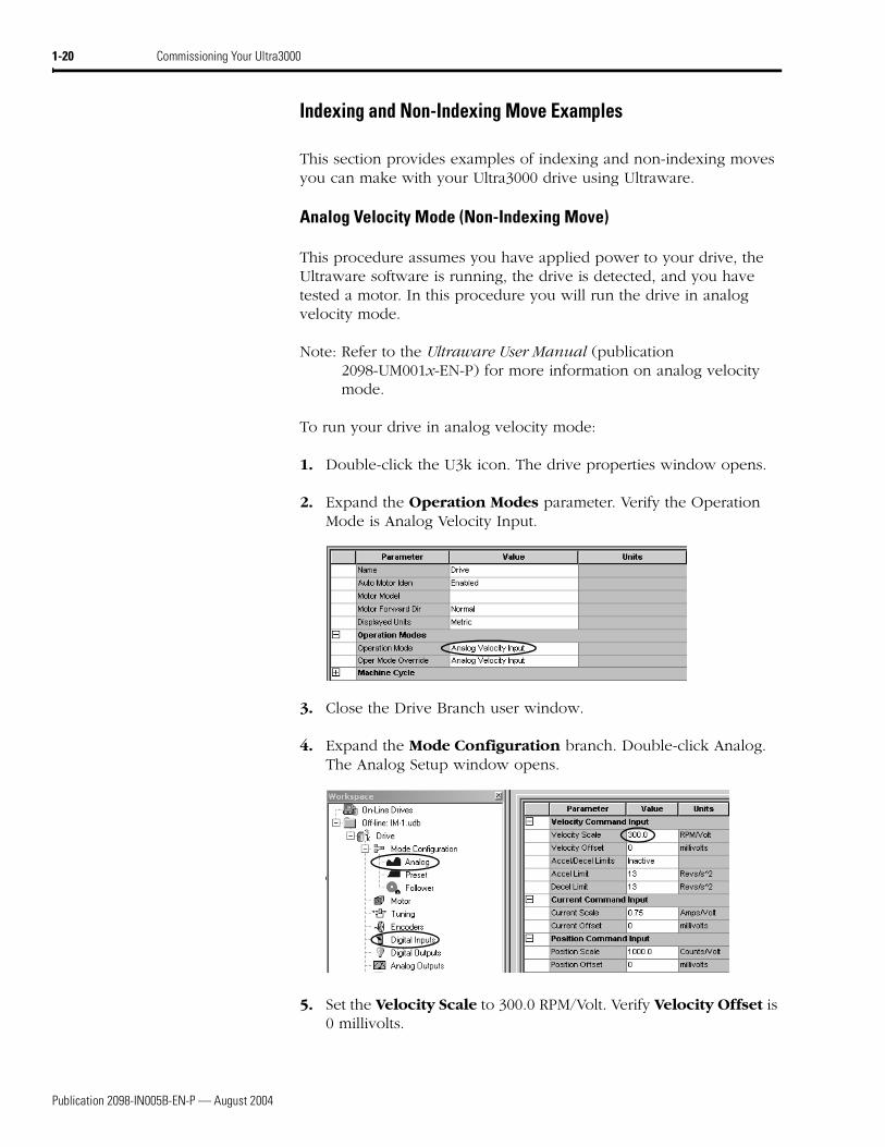
2. Expand the Operation Modes parameter. Verify the Operation Mode is Analog Velocity Input.
3. Close the Drive Branch user window.
4. Expand the Mode Configuration branch. Double-click Analog. The Analog Setup window opens.
5. Set the Velocity Scale to 300.0 RPM/Volt. Verify Velocity Offset is 0 millivolts.
Publication 2098-IN005B-EN-P — August 2004
Commissioning Your Ultra3000 1-21
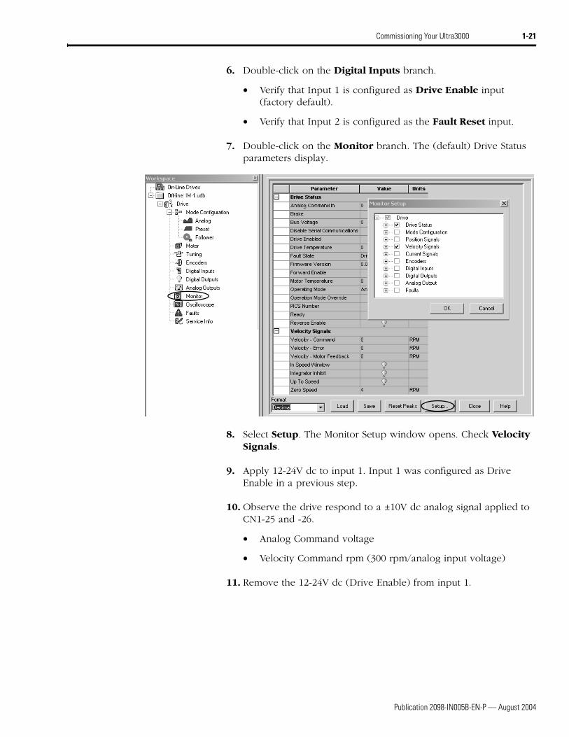
6. Double-click on the Digital Inputs branch.
• Verify that Input 1 is configured as Drive Enable input (factory default).
• Verify that Input 2 is configured as the Fault Reset input.
7. Double-click on the Monitor branch. The (default) Drive Status parameters display.
11. Remove the 12-24V dc (Drive Enable) from input 1.
Publication 2098-IN005B-EN-P — August 2004
1-22 Commissioning Your Ultra3000
Preset Velocity Control (Non-Indexing Move)
This procedure assumes you have applied power to your drive, the Ultraware software is running, the drive is detected, and you have tested a motor. In this procedure you will run the drive using preset velocity control.
Note: Refer to the Ultraware User Manual (publication 2098-UM001x-EN-P) for more information on preset velocity control.
To use preset velocity control:
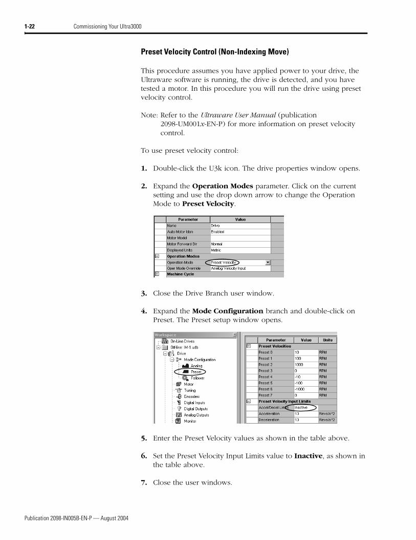
1. Double-click the U3k icon. The drive properties window opens.
2. Expand the Operation Modes parameter. Click on the current setting and use the drop down arrow to change the Operation Mode to Preset Velocity.
3. Close the Drive Branch user window.
4. Expand the Mode Configuration branch and double-click on Preset. The Preset setup window opens.
5. Enter the Preset Velocity values as shown in the table above.
6. Set the Preset Velocity Input Limits value to Inactive, as shown in the table above.
7. Close the user windows.
Publication 2098-IN005B-EN-P — August 2004
Commissioning Your Ultra3000 1-23
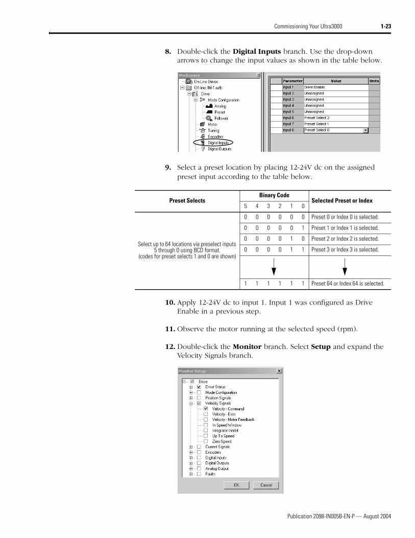
8. Double-click the Digital Inputs branch. Use the drop-down arrows to change the input values as shown in the table below.
9. Select a preset location by placing 12-24V dc on the assigned preset input according to the table below.
10. Apply 12-24V dc to input 1. Input 1 was configured as Drive Enable in a previous step.
11. Observe the motor running at the selected speed (rpm).
12. Double-click the Monitor branch. Select Setup and expand the Velocity Signals branch.
Preset SelectsBinary Code
Selected Preset or Index5 4 3 2 1 0
Select up to 64 locations via preselect inputs 5 through 0 using BCD format.
(codes for preset selects 1 and 0 are shown)
0 0 0 0 0 0 Preset 0 or Index 0 is selected.
0 0 0 0 0 1 Preset 1 or Index 1 is selected.
0 0 0 0 1 0 Preset 2 or Index 2 is selected.
0 0 0 0 1 1 Preset 3 or Index 3 is selected.
1 1 1 1 1 1 Preset 64 or Index 64 is selected.
Publication 2098-IN005B-EN-P — August 2004
1-24 Commissioning Your Ultra3000
13. Check Velocity - Command and click OK.
14. Go to the Monitor Branch and verify the Velocity - Command signal coincides with the selected preset value.
15. Remove the 12-24V dc (Drive Enable) from input 1.
Master Follower and Preset Gear Ratios (Non-Indexing Move)
This procedure assumes you have applied power to your drive, the Ultraware software is running, the drive is detected, and you have tested a motor. Also assumed is an external auxiliary incremental encoder wired to CN1-1 and -2 (power) and CN1-4, through -9 (encoder signals). In this procedure you will run the drive in position follower (Master Encoder) mode.
Note: Refer to the Ultraware User Manual (publication 2098-UM001x-EN-P) for more information on position follower mode.
To run the drive in position follower mode:
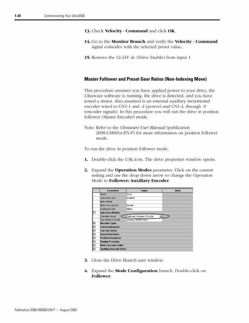
1. Double-click the U3k icon. The drive properties window opens.
2. Expand the Operation Modes parameter. Click on the current setting and use the drop down arrow to change the Operation Mode to Follower: Auxiliary Encoder.
3. Close the Drive Branch user window.
4. Expand the Mode Configuration branch. Double-click on Follower.
Publication 2098-IN005B-EN-P — August 2004
Commissioning Your Ultra3000 1-25
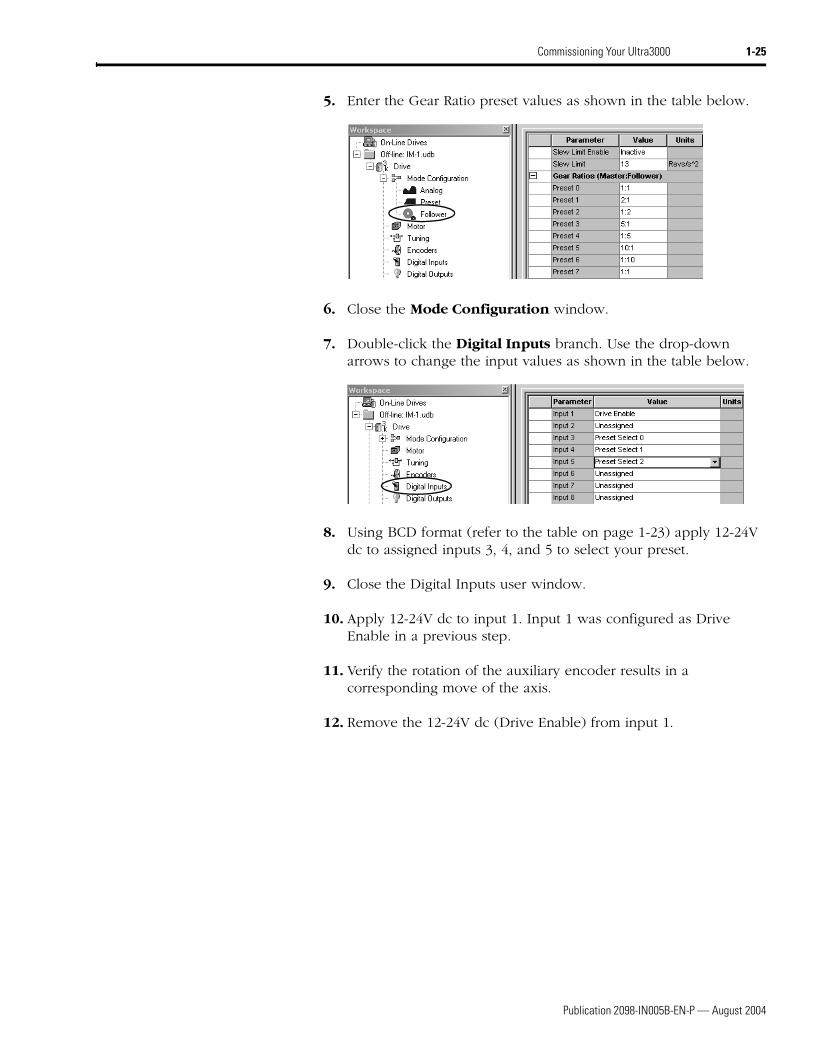
5. Enter the Gear Ratio preset values as shown in the table below.
6. Close the Mode Configuration window.
7. Double-click the Digital Inputs branch. Use the drop-down arrows to change the input values as shown in the table below.
8. Using BCD format (refer to the table on page 1-23) apply 12-24V dc to assigned inputs 3, 4, and 5 to select your preset.
9. Close the Digital Inputs user window.
10. Apply 12-24V dc to input 1. Input 1 was configured as Drive Enable in a previous step.
11. Verify the rotation of the auxiliary encoder results in a corresponding move of the axis.
12. Remove the 12-24V dc (Drive Enable) from input 1.
Publication 2098-IN005B-EN-P — August 2004
1-26 Commissioning Your Ultra3000
Incremental Indexing (Indexing Move)
This procedure assumes you have applied power to your indexing drive, the Ultraware software is running, the drive is detected, and you have tested a motor. In this procedure you will run the drive in incremental indexing mode.
Note: Refer to the Ultraware User Manual (publication 2098-UM001x-EN-P) for more information on incremental indexing moves.
To set parameters for an incremental indexing move:
1. Double-click the U3k icon. The drive properties window opens.
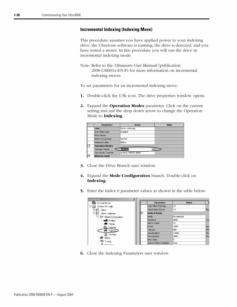
2. Expand the Operation Modes parameter. Click on the current setting and use the drop down arrow to change the Operation Mode to Indexing.
3. Close the Drive Branch user window.
4. Expand the Mode Configuration branch. Double-click on Indexing.
5. Enter the Index 0 parameter values as shown in the table below.
6. Close the Indexing Parameters user window.
Publication 2098-IN005B-EN-P — August 2004
Commissioning Your Ultra3000 1-27
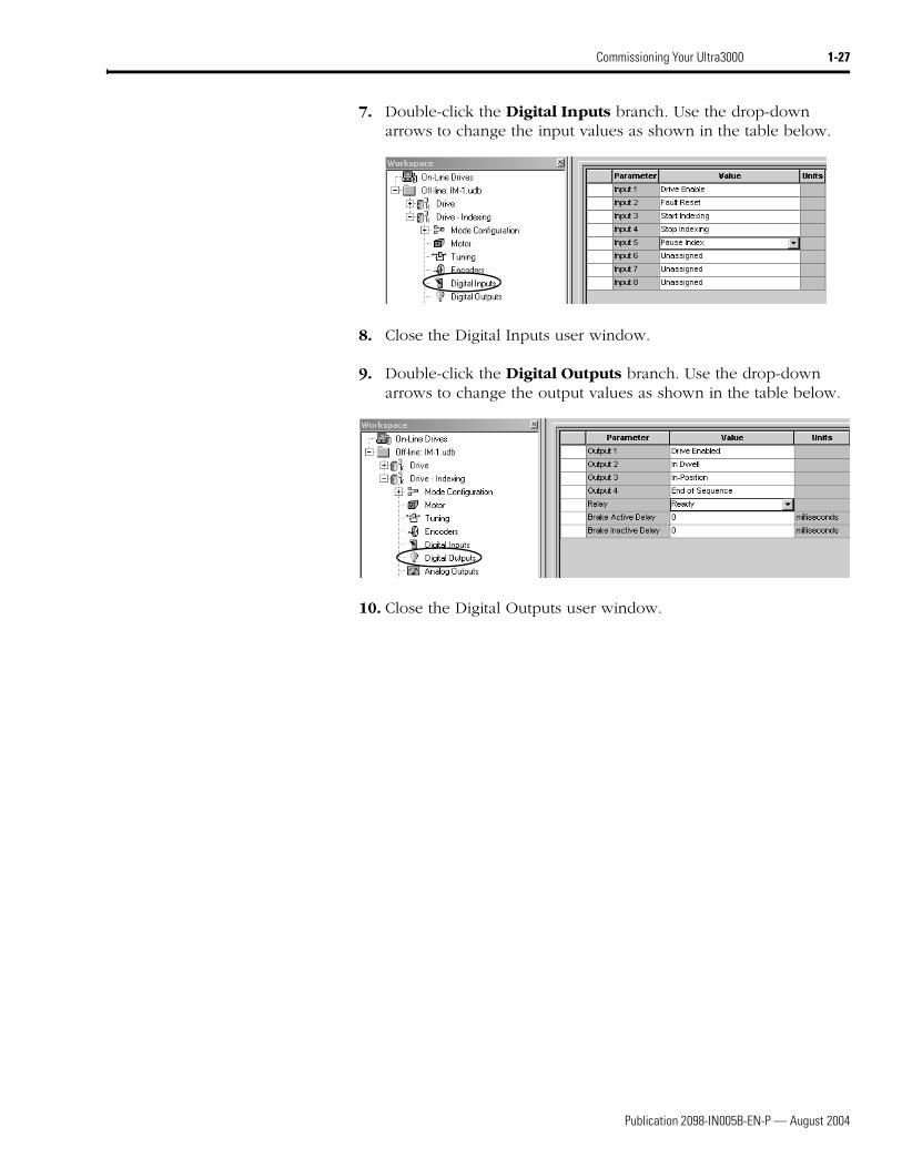
7. Double-click the Digital Inputs branch. Use the drop-down arrows to change the input values as shown in the table below.
8. Close the Digital Inputs user window.
9. Double-click the Digital Outputs branch. Use the drop-down arrows to change the output values as shown in the table below.
10. Close the Digital Outputs user window.
Publication 2098-IN005B-EN-P — August 2004
1-28 Commissioning Your Ultra3000
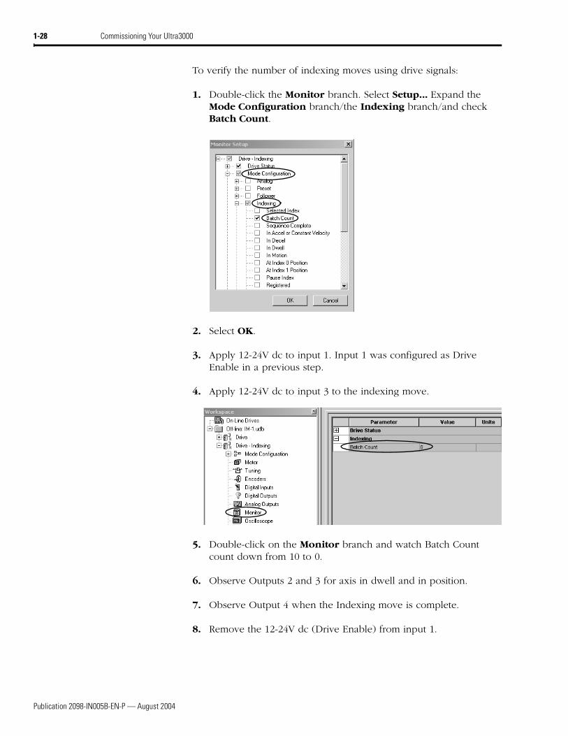
To verify the number of indexing moves using drive signals:
1. Double-click the Monitor branch. Select Setup... Expand the Mode Configuration branch/the Indexing branch/and check Batch Count.
2. Select OK.
3. Apply 12-24V dc to input 1. Input 1 was configured as Drive Enable in a previous step.
4. Apply 12-24V dc to input 3 to the indexing move.
5. Double-click on the Monitor branch and watch Batch Count count down from 10 to 0.
6. Observe Outputs 2 and 3 for axis in dwell and in position.
7. Observe Output 4 when the Indexing move is complete.
8. Remove the 12-24V dc (Drive Enable) from input 1.
Publication 2098-IN005B-EN-P — August 2004
Commissioning Your Ultra3000 1-29
To use the stop indexing feature:
1. Apply 12-24V dc to input 1. Input 1 was configured as Drive Enable in a previous step.
2. Apply 12-24V dc to input 3 to the indexing move.
3. Apply 12-24V dc to input 4 and verify that the indexing move has stopped.
4. Apply 12-24V dc to input 3 (again) and verify the original indexing move is re-initiated.
5. Apply 12-24V dc to input 5 and verify the index move is paused.
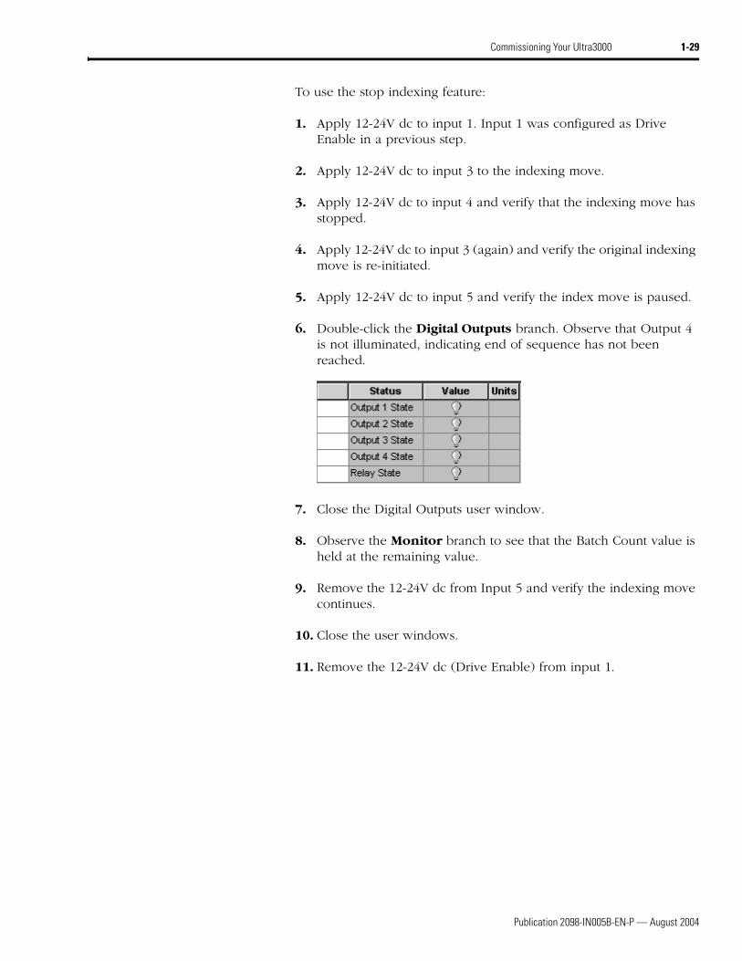
6. Double-click the Digital Outputs branch. Observe that Output 4 is not illuminated, indicating end of sequence has not been reached.
7. Close the Digital Outputs user window.
8. Observe the Monitor branch to see that the Batch Count value is held at the remaining value.
9. Remove the 12-24V dc from Input 5 and verify the indexing move continues.
10. Close the user windows.
11. Remove the 12-24V dc (Drive Enable) from input 1.
Publication 2098-IN005B-EN-P — August 2004
1-30 Commissioning Your Ultra3000
Absolute Indexing (Indexing Move)
This procedure assumes you have applied power to your indexing drive, the Ultraware software is running, the drive is detected, and you have tested a motor. In this procedure you will run the drive in absolute indexing mode.
Note: Refer to the Ultraware User Manual (publication 2098-UM001x-EN-P) for more information on absolute indexing moves.
To set parameters for an absolute indexing move:
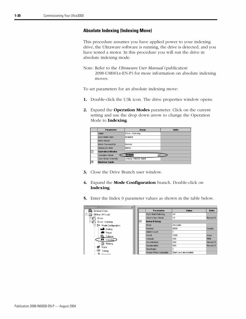
1. Double-click the U3k icon. The drive properties window opens.
2. Expand the Operation Modes parameter. Click on the current setting and use the drop down arrow to change the Operation Mode to Indexing.
3. Close the Drive Branch user window.
4. Expand the Mode Configuration branch. Double-click on Indexing.
5. Enter the Index 0 parameter values as shown in the table below.
Publication 2098-IN005B-EN-P — August 2004
Commissioning Your Ultra3000 1-31
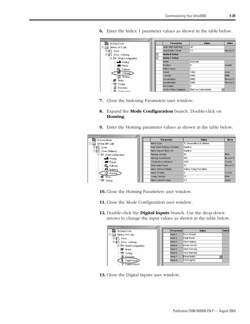
6. Enter the Index 1 parameter values as shown in the table below.
7. Close the Indexing Parameters user window.
8. Expand the Mode Configuration branch. Double-click on Homing.
9. Enter the Homing parameter values as shown in the table below.
10. Close the Homing Parameters user window.
11. Close the Mode Configuration user window.
12. Double-click the Digital Inputs branch. Use the drop-down arrows to change the input values as shown in the table below.
13. Close the Digital Inputs user window.
Publication 2098-IN005B-EN-P — August 2004
1-32 Commissioning Your Ultra3000
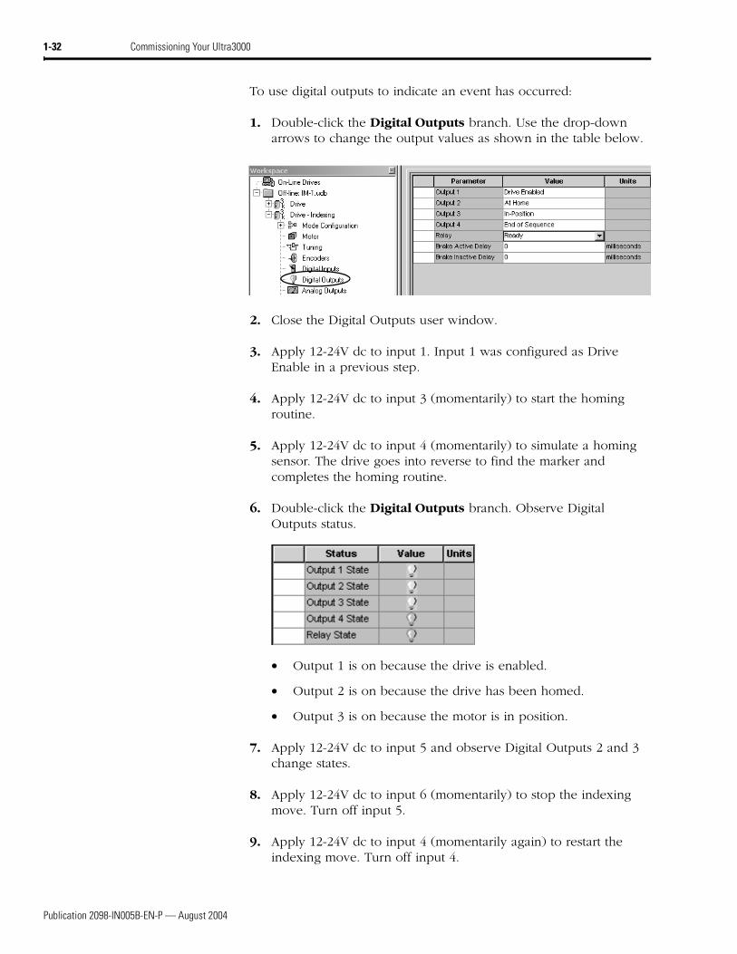
To use digital outputs to indicate an event has occurred:
1. Double-click the Digital Outputs branch. Use the drop-down arrows to change the output values as shown in the table below.
2. Close the Digital Outputs user window.
3. Apply 12-24V dc to input 1. Input 1 was configured as Drive Enable in a previous step.
4. Apply 12-24V dc to input 3 (momentarily) to start the homing routine.
5. Apply 12-24V dc to input 4 (momentarily) to simulate a homing sensor. The drive goes into reverse to find the marker and completes the homing routine.
6. Double-click the Digital Outputs branch. Observe Digital Outputs status.
• Output 1 is on because the drive is enabled.
• Output 2 is on because the drive has been homed.
• Output 3 is on because the motor is in position.
7. Apply 12-24V dc to input 5 and observe Digital Outputs 2 and 3 change states.
8. Apply 12-24V dc to input 6 (momentarily) to stop the indexing move. Turn off input 5.
9. Apply 12-24V dc to input 4 (momentarily again) to restart the indexing move. Turn off input 4.
Publication 2098-IN005B-EN-P — August 2004
Commissioning Your Ultra3000 1-33
10. Apply 12-24V dc to input 7 to pause the indexing move. Remove the 12-24V dc and observe the index move continue.
11. Close the user windows.
12. Remove the 12-24V dc (Drive Enable) from input 1.
Publication 2098-IN005B-EN-P — August 2004
1-34 Commissioning Your Ultra3000
Configuring Your Ultra3000 Drive with Logix
In this section you will configure your Ultra3000 drive using Ultraware software, configure the Logix analog motion module using RSLogix 5000, and test/tune your axis.
Configuring Your Ultra3000 Drive
To configure your Ultra3000 drive:
1. Apply power to your Ultra3000 drive (refer to the section Applying Power To Your Ultra3000 Drive).
2. Start your Ultraware software and ensure your Ultra3000 drive is detected (refer to the section Detecting Your Ultra3000 Drive).
3. Select a motor (refer to the section Selecting a Motor).
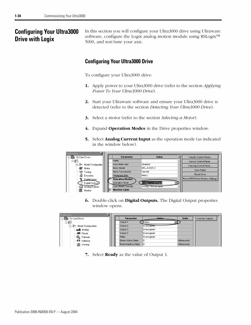
4. Expand Operation Modes in the Drive properties window.
5. Select Analog Current Input as the operation mode (as indicated in the window below).
6. Double-click on Digital Outputs. The Digital Output properties window opens.
7. Select Ready as the value of Output 1.
Publication 2098-IN005B-EN-P — August 2004
Commissioning Your Ultra3000 1-35
Configuring Your Logix Analog Motion Module
This procedure assumes that you have finished configuring your Ultra3000 drive.
For greater detail on the RSLogix 5000 software as it applies to ControlLogix and SoftLogix modules, refer to the table below for the appropriate publication.
If you have already configured your Logix module using one of the setup and configuration manuals listed above, go directly to Testing and Tuning Your Axis (page 1-41). If not, go to Configuring Your Logix Controller beginning below.
Configuring Your Logix Controller
To configure your Logix controller:
1. Apply power to your Logix chassis/PC containing the analog motion module and open your RSLogix 5000 software.
2. Select New in the File menu. The New Controller window opens.
• Select controller type
• Name the file
• Select the ControlLogix chassis size
• Select the ControlLogix processor slot
3. Select OK.
4. Select Controller Properties in the edit menu. The Controller Properties window opens.
For: Refer to this Document Publication Number:
Detailed information on configuring and troubleshooting your ControlLogix motion module
ControlLogix Motion Module Setup and Configuration Manual 1756-UM006x-EN-P
Detailed information on configuring and troubleshooting your SoftLogix PCI card
SoftLogix Motion Card Setup and Configuration Manual 1784-UM003x-EN-P
Publication 2098-IN005B-EN-P — August 2004
1-36 Commissioning Your Ultra3000
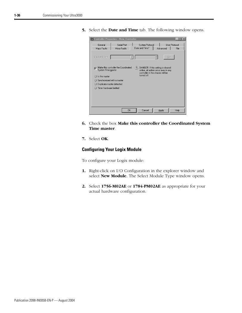
5. Select the Date and Time tab. The following window opens.
6. Check the box Make this controller the Coordinated System Time master.
7. Select OK.
Configuring Your Logix Module
To configure your Logix module:
1. Right-click on I/O Configuration in the explorer window and select New Module. The Select Module Type window opens.
2. Select 1756-M02AE or 1784-PM02AE as appropriate for your actual hardware configuration.
Publication 2098-IN005B-EN-P — August 2004
Commissioning Your Ultra3000 1-37
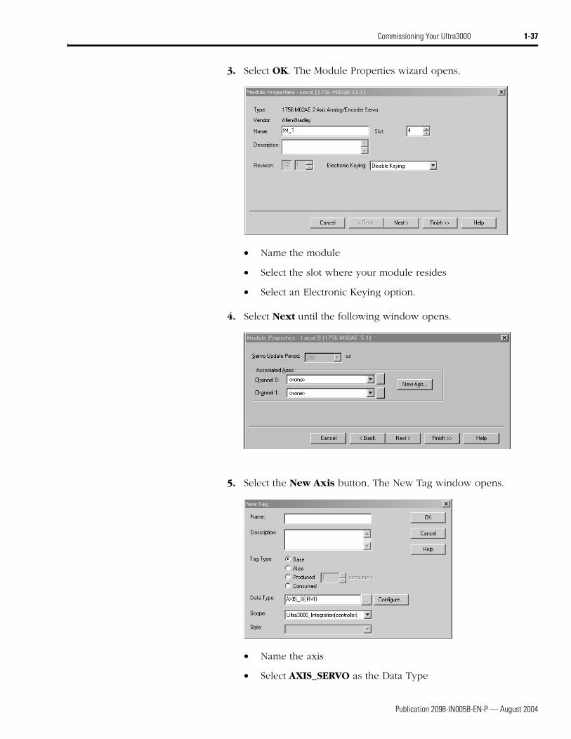
3. Select OK. The Module Properties wizard opens.
• Name the module
• Select the slot where your module resides
• Select an Electronic Keying option.
4. Select Next until the following window opens.
5. Select the New Axis button. The New Tag window opens.
• Name the axis
• Select AXIS_SERVO as the Data Type
Publication 2098-IN005B-EN-P — August 2004
1-38 Commissioning Your Ultra3000
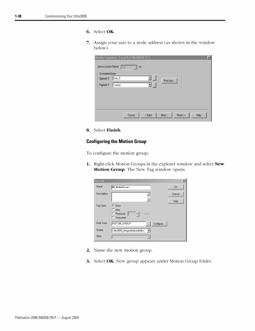
6. Select OK.
7. Assign your axis to a node address (as shown in the window below).
8. Select Finish.
Configuring the Motion Group
To configure the motion group:
1. Right-click Motion Groups in the explorer window and select New Motion Group. The New Tag window opens.
2. Name the new motion group.
3. Select OK. New group appears under Motion Group folder.
Publication 2098-IN005B-EN-P — August 2004
Commissioning Your Ultra3000 1-39
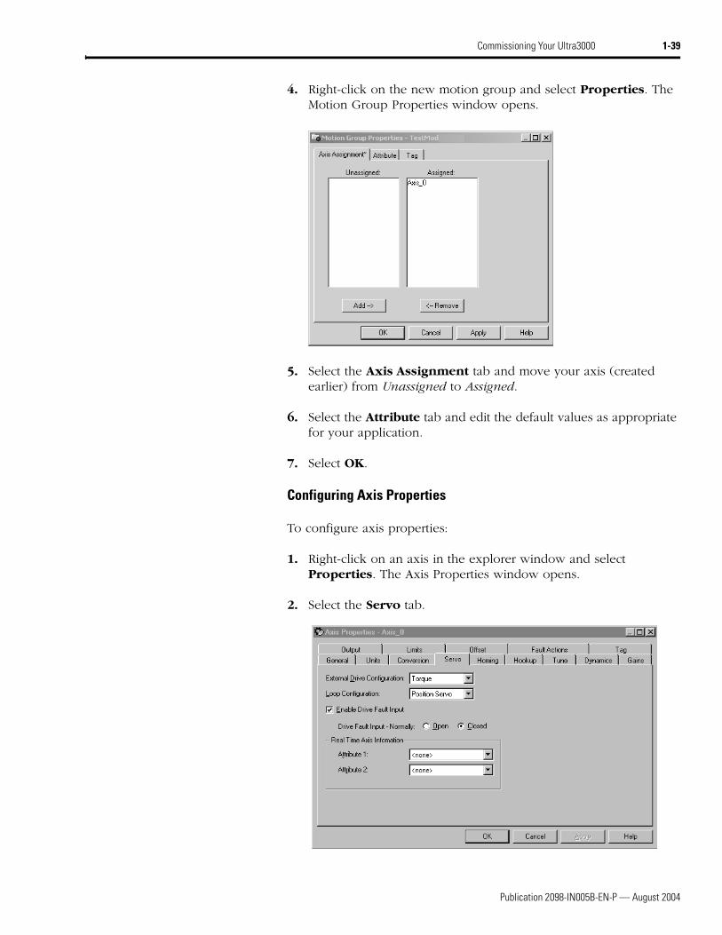
4. Right-click on the new motion group and select Properties. The Motion Group Properties window opens.
5. Select the Axis Assignment tab and move your axis (created earlier) from Unassigned to Assigned.
6. Select the Attribute tab and edit the default values as appropriate for your application.
7. Select OK.
Configuring Axis Properties
To configure axis properties:
1. Right-click on an axis in the explorer window and select Properties. The Axis Properties window opens.
2. Select the Servo tab.
Publication 2098-IN005B-EN-P — August 2004
1-40 Commissioning Your Ultra3000
3. Select Torque as the External Drive Configuration.
4. Check the box Enable Drive Fault Input and select Normally Closed.
5. Select the Units tab and edit default values as appropriate for your application.
6. Select the Conversion tab and edit default values as appropriate for your application.
7. Select OK.
8. Verify your Logix program and save the file.
Downloading Your Program
After completing the Logix configuration you must download your program to the Logix processor.
Publication 2098-IN005B-EN-P — August 2004
Commissioning Your Ultra3000 1-41
Testing and Tuning Your Axis
This procedure assumes that you have configured your Ultra3000 and the analog motion module.
For greater detail on the RSLogix 5000 software as it applies to ControlLogix and SoftLogix modules, refer to the table below for the appropriate publication.
If you have already tested and tuned your axis using one of the setup and configuration manuals listed above, you are finished commissioning your drive. If not, go to Testing Your Axis beginning below.
Testing Your Axis
To test your axis:
1. Remove the load from your axis.
2. Right-click on the axis in your Motion Group folder in the explorer window and select Axis Properties. The Axis Properties window opens.
IMPORTANT Before proceeding with testing and tuning your axis, verify that the seven-segment status LEDs are actively cycling in a full circle.
For: Refer to this Document Publication Number:
Detailed information on configuring and troubleshooting your ControlLogix motion module
ControlLogix Motion Module Setup and Configuration Manual 1756-UM006x-EN-P
Detailed information on configuring and troubleshooting your SoftLogix PCI card
SoftLogix Motion Card Setup and Configuration Manual 1784-UM003x-EN-P
Publication 2098-IN005B-EN-P — August 2004
1-42 Commissioning Your Ultra3000
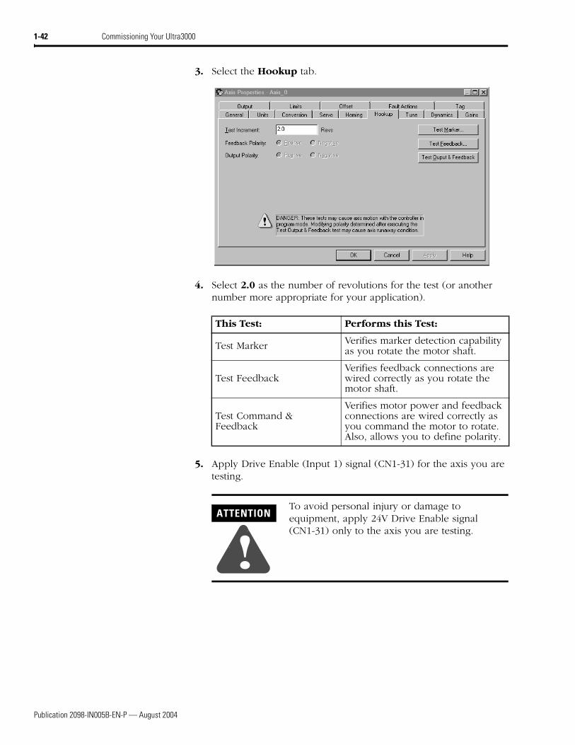
3. Select the Hookup tab.
4. Select 2.0 as the number of revolutions for the test (or another number more appropriate for your application).
5. Apply Drive Enable (Input 1) signal (CN1-31) for the axis you are testing.
This Test: Performs this Test:
Test Marker Verifies marker detection capability as you rotate the motor shaft.
Test FeedbackVerifies feedback connections are wired correctly as you rotate the motor shaft.
Test Command & Feedback
Verifies motor power and feedback connections are wired correctly as you command the motor to rotate. Also, allows you to define polarity.
ATTENTION
!To avoid personal injury or damage to equipment, apply 24V Drive Enable signal (CN1-31) only to the axis you are testing.
Publication 2098-IN005B-EN-P — August 2004
Commissioning Your Ultra3000 1-43
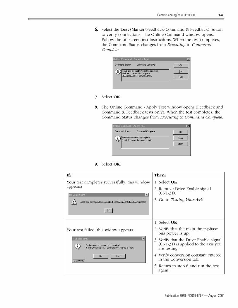
6. Select the Test (Marker/Feedback/Command & Feedback) button to verify connections. The Online Command window opens. Follow the on-screen test instructions. When the test completes, the Command Status changes from Executing to Command Complete
7. Select OK.
8. The Online Command - Apply Test window opens (Feedback and Command & Feedback tests only). When the test completes, the Command Status changes from Executing to Command Complete.
9. Select OK.
If: Then:
Your test completes successfully, this window appears:
1. Select OK.
2. Remove Drive Enable signal (CN1-31).
3. Go to Tuning Your Axis.
Your test failed, this widow appears:
1. Select OK.
2. Verify that the main three-phase bus power is up.
3. Verify that the Drive Enable signal (CN1-31) is applied to the axis you are testing.
4. Verify conversion constant entered in the Conversion tab.
5. Return to step 6 and run the test again.
Publication 2098-IN005B-EN-P — August 2004
1-44 Commissioning Your Ultra3000
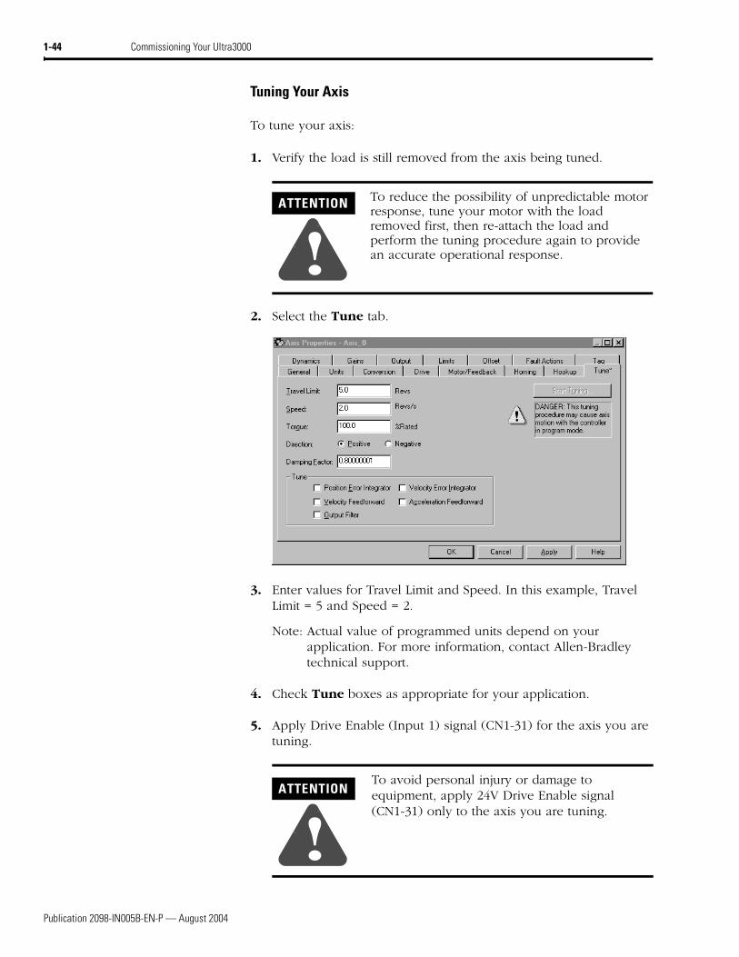
Tuning Your Axis
To tune your axis:
1. Verify the load is still removed from the axis being tuned.
2. Select the Tune tab.
3. Enter values for Travel Limit and Speed. In this example, Travel Limit = 5 and Speed = 2.
Note: Actual value of programmed units depend on your application. For more information, contact Allen-Bradley technical support.
4. Check Tune boxes as appropriate for your application.
5. Apply Drive Enable (Input 1) signal (CN1-31) for the axis you are tuning.
ATTENTION
!To reduce the possibility of unpredictable motor response, tune your motor with the load removed first, then re-attach the load and perform the tuning procedure again to provide an accurate operational response.
ATTENTION
!To avoid personal injury or damage to equipment, apply 24V Drive Enable signal (CN1-31) only to the axis you are tuning.
Publication 2098-IN005B-EN-P — August 2004
Commissioning Your Ultra3000 1-45
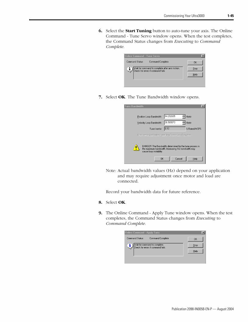
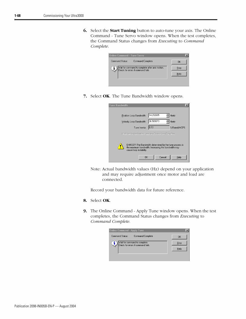
6. Select the Start Tuning button to auto-tune your axis. The Online Command - Tune Servo window opens. When the test completes, the Command Status changes from Executing to Command Complete.
7. Select OK. The Tune Bandwidth window opens.
Note: Actual bandwidth values (Hz) depend on your application and may require adjustment once motor and load are connected.
Record your bandwidth data for future reference.
8. Select OK.
9. The Online Command - Apply Tune window opens. When the test completes, the Command Status changes from Executing to Command Complete.
Publication 2098-IN005B-EN-P — August 2004
1-46 Commissioning Your Ultra3000
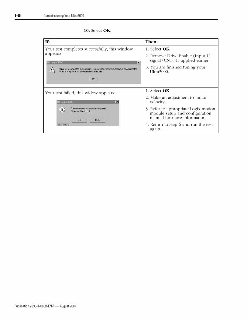
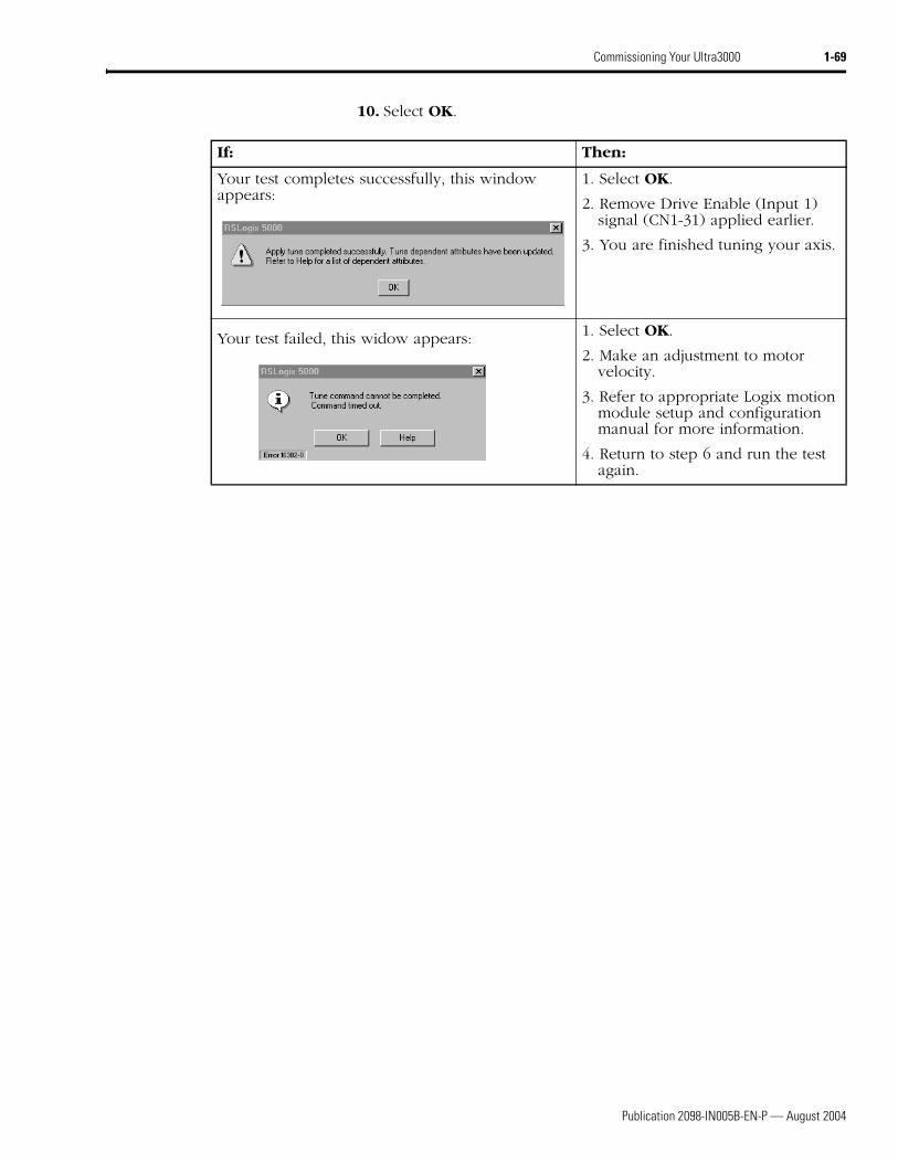
10. Select OK.
If: Then:
Your test completes successfully, this window appears:
1. Select OK.
2. Remove Drive Enable (Input 1) signal (CN1-31) applied earlier.
3. You are finished tuning your Ultra3000.
Your test failed, this widow appears: 1. Select OK.
2. Make an adjustment to motor velocity.
3. Refer to appropriate Logix motion module setup and configuration manual for more information.
4. Return to step 6 and run the test again.
Publication 2098-IN005B-EN-P — August 2004
Commissioning Your Ultra3000 1-47
Configuring Your Ultra3000 with SERCOS interface Drive
The procedures in this section apply to Ultra3000-SE drives (2098-DSD-xxx-SE and -HVxxx-SE) and describe how to:
• Configure your Ultra3000-SE drive
• Configure your SERCOS interface module using RSLogix 5000 software
• Download your program to your Logix controller
• Apply power to your Ultra3000-SE drive
• Test and tune your motor using RSLogix 5000 software.
These procedures assume you have connected the fiber-optic cables between your Ultra3000-SE drive and the SERCOS interface module.
Front Panel Connections
This section provides front panel connection information for your Ultra3000-SE and the ControlLogix SERCOS interface module or SoftLogix SERCOS PCI card.
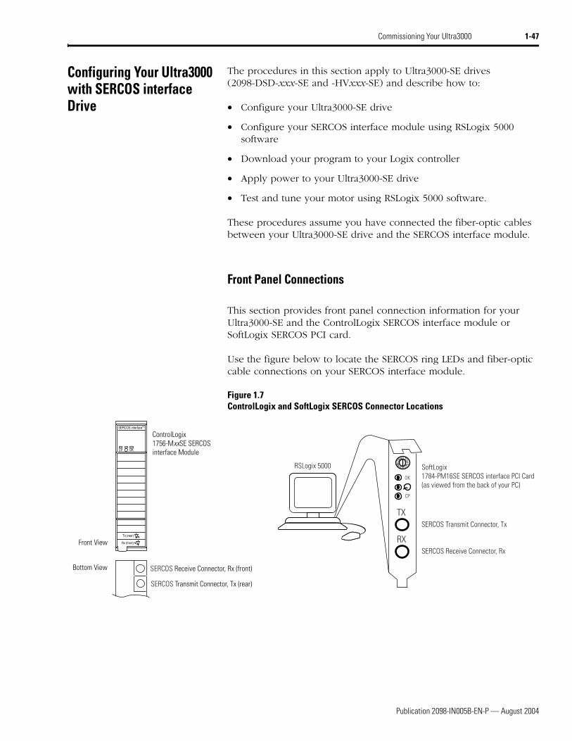
Use the figure below to locate the SERCOS ring LEDs and fiber-optic cable connections on your SERCOS interface module.
Figure 1.7ControlLogix and SoftLogix SERCOS Connector Locations
SERCOS interfaceTM
Tx (rear)
Rx (front)
OKCP
0
8
4
C 675
321
9AB
ED F
TX
RX
OK
CP
ControlLogix1756-MxxSE SERCOSinterface Module
SERCOS Receive Connector, Rx (front)
SERCOS Transmit Connector, Tx (rear)
Front View
Bottom View
SERCOS Receive Connector, Rx
SERCOS Transmit Connector, Tx
SoftLogix1784-PM16SE SERCOS interface PCI Card(as viewed from the back of your PC)
RSLogix 5000
Publication 2098-IN005B-EN-P — August 2004
1-48 Commissioning Your Ultra3000
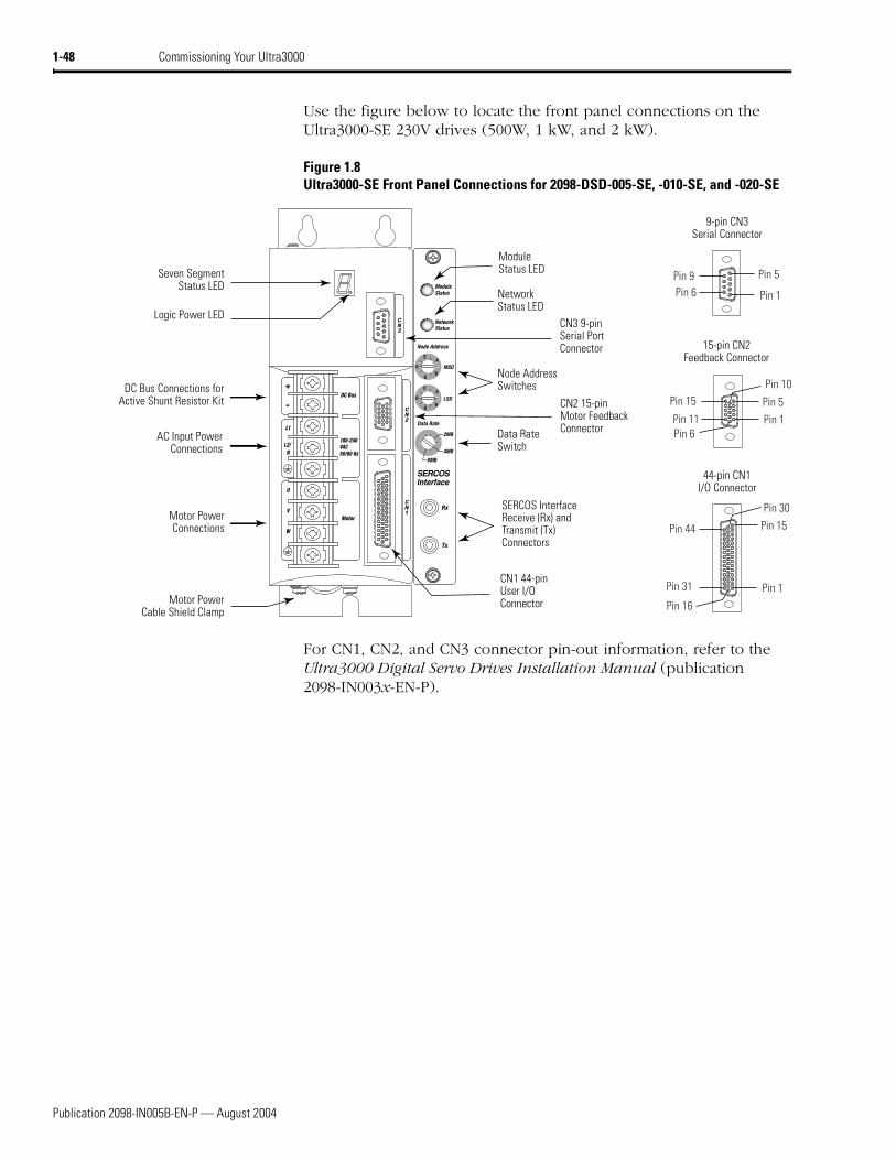
Use the figure below to locate the front panel connections on the Ultra3000-SE 230V drives (500W, 1 kW, and 2 kW).
Figure 1.8Ultra3000-SE Front Panel Connections for 2098-DSD-005-SE, -010-SE, and -020-SE
For CN1, CN2, and CN3 connector pin-out information, refer to the Ultra3000 Digital Servo Drives Installation Manual (publication 2098-IN003x-EN-P).
Pin 11Pin 6
Pin 15
Pin 1
Pin 10
Pin 5
Pin 30
Pin 44
Pin 1
Pin 15
Pin 16
Pin 31
Pin 6Pin 9
Pin 1
Pin 5
8
CN1 44-pinUser I/OConnector
CN2 15-pinMotor FeedbackConnector
CN3 9-pinSerial PortConnector
Logic Power LED
Seven SegmentStatus LED
DC Bus Connections forActive Shunt Resistor Kit
AC Input Power Connections
Motor Power Connections
ModuleStatus LED
NetworkStatus LED
Node Address Switches
Data RateSwitch
SERCOS Interface Receive (Rx) and Transmit (Tx) Connectors
Motor Power Cable Shield Clamp
9-pin CN3Serial Connector
15-pin CN2Feedback Connector
44-pin CN1I/O Connector
Publication 2098-IN005B-EN-P — August 2004
Commissioning Your Ultra3000 1-49
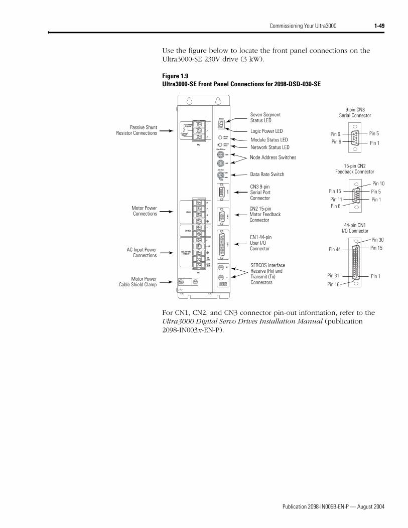
Use the figure below to locate the front panel connections on the Ultra3000-SE 230V drive (3 kW).
Figure 1.9Ultra3000-SE Front Panel Connections for 2098-DSD-030-SE
For CN1, CN2, and CN3 connector pin-out information, refer to the Ultra3000 Digital Servo Drives Installation Manual (publication 2098-IN003x-EN-P).
U
V
W
+
-
L1
L2/N
L1AUX
L2/NAUX
1
2
3
Motor
DC Bus
100-240 VAC50/60 Hz
Internal
ExternalShunt
TB2
TB1
Pin 11Pin 6
Pin 15
Pin 1
Pin 10
Pin 5
Pin 30
Pin 44
Pin 1
Pin 15
Pin 16
Pin 31
Pin 6Pin 9
Pin 1
Pin 5
8
AC Input Power Connections
Motor Power Connections
Passive Shunt Resistor Connections
Seven Segment Status LED
Logic Power LED
CN3 9-pin Serial Port Connector
CN2 15-pin Motor Feedback Connector
CN1 44-pin User I/O Connector
SERCOS interface Receive (Rx) and Transmit (Tx)Connectors
Node Address Switches
Data Rate Switch
Module Status LEDNetwork Status LED
Motor Power Cable Shield Clamp
9-pin CN3Serial Connector
15-pin CN2Feedback Connector
44-pin CN1I/O Connector
Publication 2098-IN005B-EN-P — August 2004
1-50 Commissioning Your Ultra3000
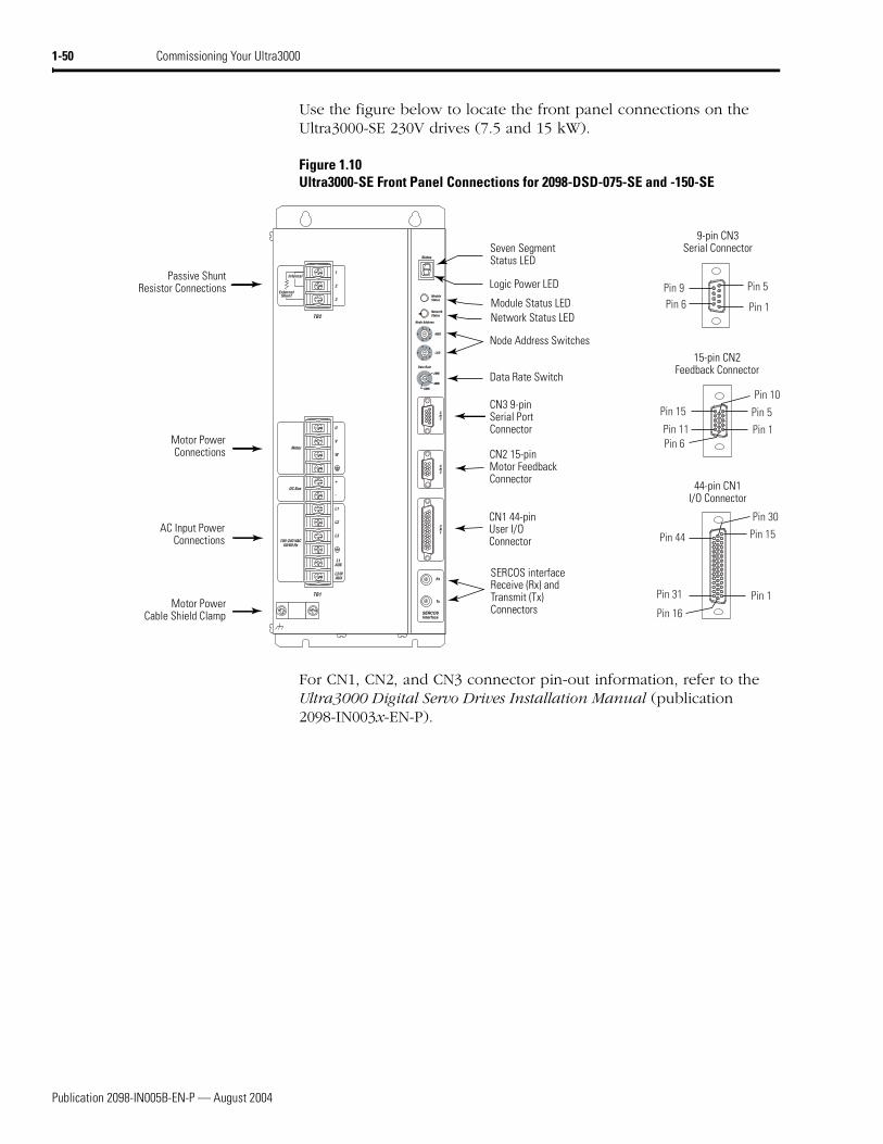
Use the figure below to locate the front panel connections on the Ultra3000-SE 230V drives (7.5 and 15 kW).
Figure 1.10Ultra3000-SE Front Panel Connections for 2098-DSD-075-SE and -150-SE
For CN1, CN2, and CN3 connector pin-out information, refer to the Ultra3000 Digital Servo Drives Installation Manual (publication 2098-IN003x-EN-P).
U
V
W
+
-
L1
L2
L3
L1AUX
L2/NAUX
Motor
DC Bus
100-240 VAC50/60 Hz
Internal
ExternalShunt
1
2
3
TB2
TB1
Pin 11Pin 6
Pin 15
Pin 1
Pin 10
Pin 5
Pin 30
Pin 44
Pin 1
Pin 15
Pin 16
Pin 31
Pin 6Pin 9
Pin 1
Pin 5
8
AC Input Power Connections
Motor Power Connections
Passive Shunt Resistor Connections
Seven Segment Status LED
Logic Power LED
CN3 9-pin Serial Port Connector
CN2 15-pin Motor Feedback Connector
CN1 44-pin User I/O Connector
SERCOS interface Receive (Rx) and Transmit (Tx)Connectors
Node Address Switches
Data Rate Switch
Module Status LEDNetwork Status LED
Motor Power Cable Shield Clamp
9-pin CN3Serial Connector
15-pin CN2Feedback Connector
44-pin CN1I/O Connector
Publication 2098-IN005B-EN-P — August 2004
Commissioning Your Ultra3000 1-51
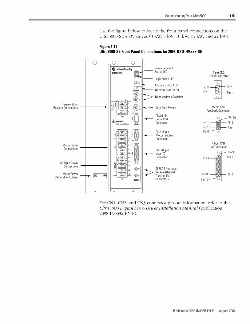
Use the figure below to locate the front panel connections on the Ultra3000-SE 460V drives (3 kW, 5 kW, 10 kW, 15 kW, and 22 kW).
Figure 1.11Ultra3000-SE Front Panel Connections for 2098-DSD-HVxxx-SE
For CN1, CN2, and CN3 connector pin-out information, refer to the Ultra3000 Digital Servo Drives Installation Manual (publication 2098-IN003x-EN-P).
W
V
U
+
-
L3
L2
L1
L1AUX
L2AUX
Mot
orDC
Bus
230-
480
VAC
50/6
0 Hz
Inte
rnal
Exte
rnal
Shu
nt 1
2
3
TB2
DANGERDANGERHazardous voltageexists after power down.
TB1
Pin 11Pin 6
Pin 15
Pin 1
Pin 10
Pin 5
Pin 30
Pin 44
Pin 1
Pin 15
Pin 16
Pin 31
Pin 6Pin 9
Pin 1
Pin 5
8
AC Input Power Connections
Motor Power Connections
Passive Shunt Resistor Connections
Seven Segment Status LED
Logic Power LED
CN3 9-pin Serial Port Connector
CN2 15-pin Motor Feedback Connector
CN1 44-pin User I/O Connector
SERCOS interface Receive (Rx) and Transmit (Tx)Connectors
Node Address Switches
Data Rate Switch
Module Status LEDNetwork Status LED
Motor Power Cable Shield Clamp
9-pin CN3Serial Connector
15-pin CN2Feedback Connector
44-pin CN1I/O Connector
Publication 2098-IN005B-EN-P — August 2004
1-52 Commissioning Your Ultra3000
Configuring Your Ultra3000 Drive
Use the following procedures to configure your Ultra3000-SE drive (2098-DSD-xxx-SE and -HVxxx-SE).
To configure your Ultra3000-SE drive:
1. Verify that there is no power applied to the drive, and the SERCOS fiber-optic cables are correctly plugged into the Tx and Rx connectors. To verify your fiber-optic cable connections, refer to the Ultra3000 Digital Servo Drives Installation Manual (publication 2098-IN003x-EN-P).
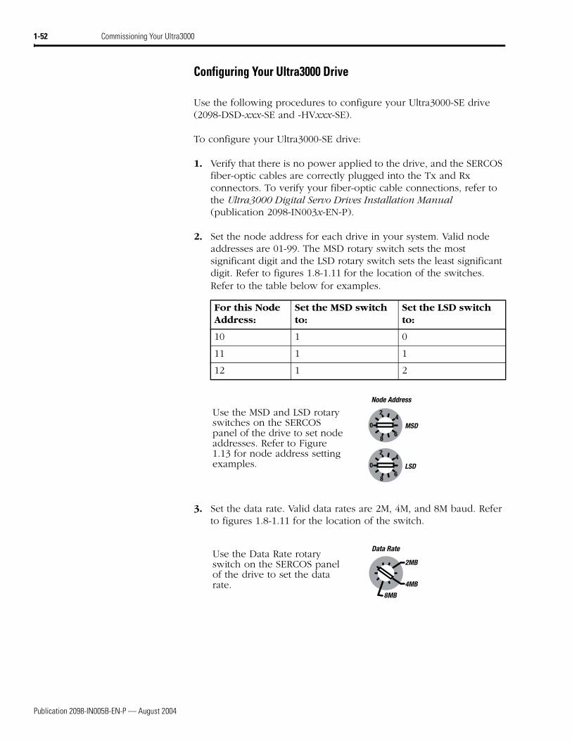
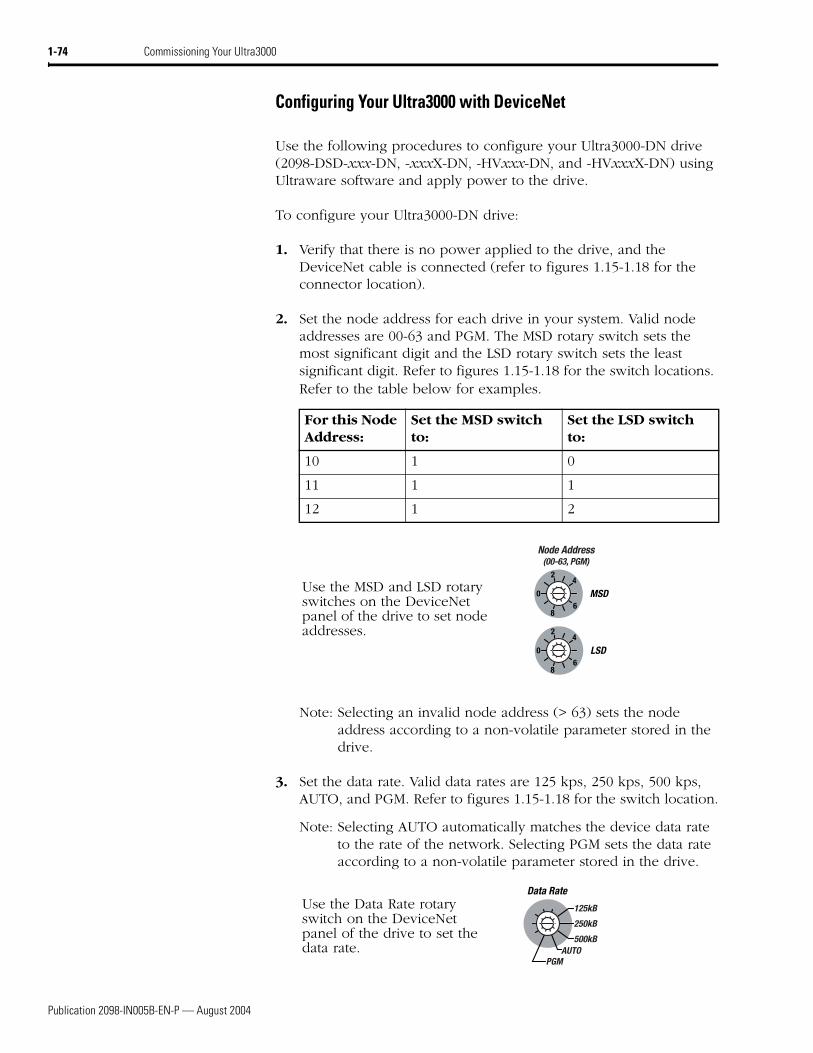
2. Set the node address for each drive in your system. Valid node addresses are 01-99. The MSD rotary switch sets the most significant digit and the LSD rotary switch sets the least significant digit. Refer to figures 1.8-1.11 for the location of the switches. Refer to the table below for examples.
3. Set the data rate. Valid data rates are 2M, 4M, and 8M baud. Refer to figures 1.8-1.11 for the location of the switch.
For this Node Address:
Set the MSD switch to:
Set the LSD switch to:
10 1 0
11 1 1
12 1 2
Use the MSD and LSD rotary switches on the SERCOS panel of the drive to set node addresses. Refer to Figure 1.13 for node address setting examples.
Use the Data Rate rotary switch on the SERCOS panel of the drive to set the data rate.
8
Publication 2098-IN005B-EN-P — August 2004
Commissioning Your Ultra3000 1-53
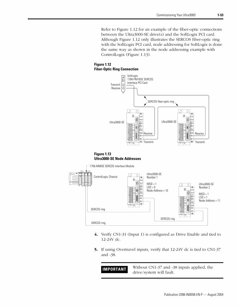
Refer to Figure 1.12 for an example of the fiber-optic connections between the Ultra3000-SE drive(s) and the SoftLogix PCI card. Although Figure 1.12 only illustrates the SERCOS fiber-optic ring with the SoftLogix PCI card, node addressing for SoftLogix is done the same way as shown in the node addressing example with ControlLogix (Figure 1.13).
Figure 1.12Fiber-Optic Ring Connection
Figure 1.13Ultra3000-SE Node Addresses
4. Verify CN1-31 (Input 1) is configured as Drive Enable and tied to 12-24V dc.
5. If using Overtravel inputs, verify that 12-24V dc is tied to CN1-37 and -38.
IMPORTANT Without CN1-37 and -38 inputs applied, the drive/system will fault.
Publication 2098-IN005B-EN-P — August 2004
1-54 Commissioning Your Ultra3000
Configuring Your Logix SERCOS interface Module
This procedure assumes that you have configured the Ultra3000-SE baud rate and optical power switches.
For greater detail on the RSLogix 5000 software as it applies to ControlLogix and SoftLogix modules, refer to the table below for the appropriate publication.
If you have already configured your Logix controller using one of the setup and configuration manuals listed above, go directly to Applying Power To Your Ultra3000 with SERCOS (page 1-61). If not, go to Configuring Your Logix Controller beginning below.
Configuring Your Logix Controller
To configure your Logix controller:
1. Apply power to your Logix chassis/PC containing the SERCOS interface module and open your RSLogix 5000 software.
2. Select New in the File menu. The New Controller window opens.
• Select controller type
• Name the file
• Select the ControlLogix chassis size
• Select the ControlLogix processor slot
3. Select OK.
4. Select Controller Properties in the edit menu. The Controller Properties window opens.
For: Refer to this Document Publication Number:
Detailed information on configuring and troubleshooting your ControlLogix motion module
ControlLogix Motion Module Setup and Configuration Manual 1756-UM006x-EN-P
Detailed information on configuring and troubleshooting your SoftLogix PCI card
SoftLogix Motion Card Setup and Configuration Manual 1784-UM003x-EN-P
Publication 2098-IN005B-EN-P — August 2004
Commissioning Your Ultra3000 1-55
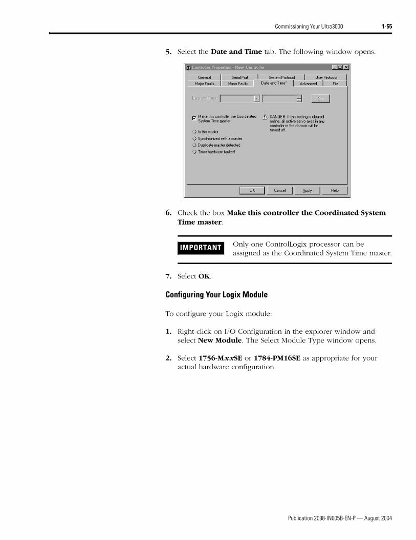
5. Select the Date and Time tab. The following window opens.
6. Check the box Make this controller the Coordinated System Time master.
7. Select OK.
Configuring Your Logix Module
To configure your Logix module:
1. Right-click on I/O Configuration in the explorer window and select New Module. The Select Module Type window opens.
2. Select 1756-MxxSE or 1784-PM16SE as appropriate for your actual hardware configuration.
IMPORTANT Only one ControlLogix processor can be assigned as the Coordinated System Time master.
Publication 2098-IN005B-EN-P — August 2004
1-56 Commissioning Your Ultra3000
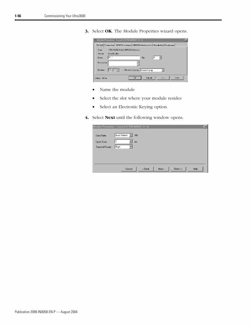
3. Select OK. The Module Properties wizard opens.
• Name the module
• Select the slot where your module resides
• Select an Electronic Keying option.
4. Select Next until the following window opens.
Publication 2098-IN005B-EN-P — August 2004
Commissioning Your Ultra3000 1-57
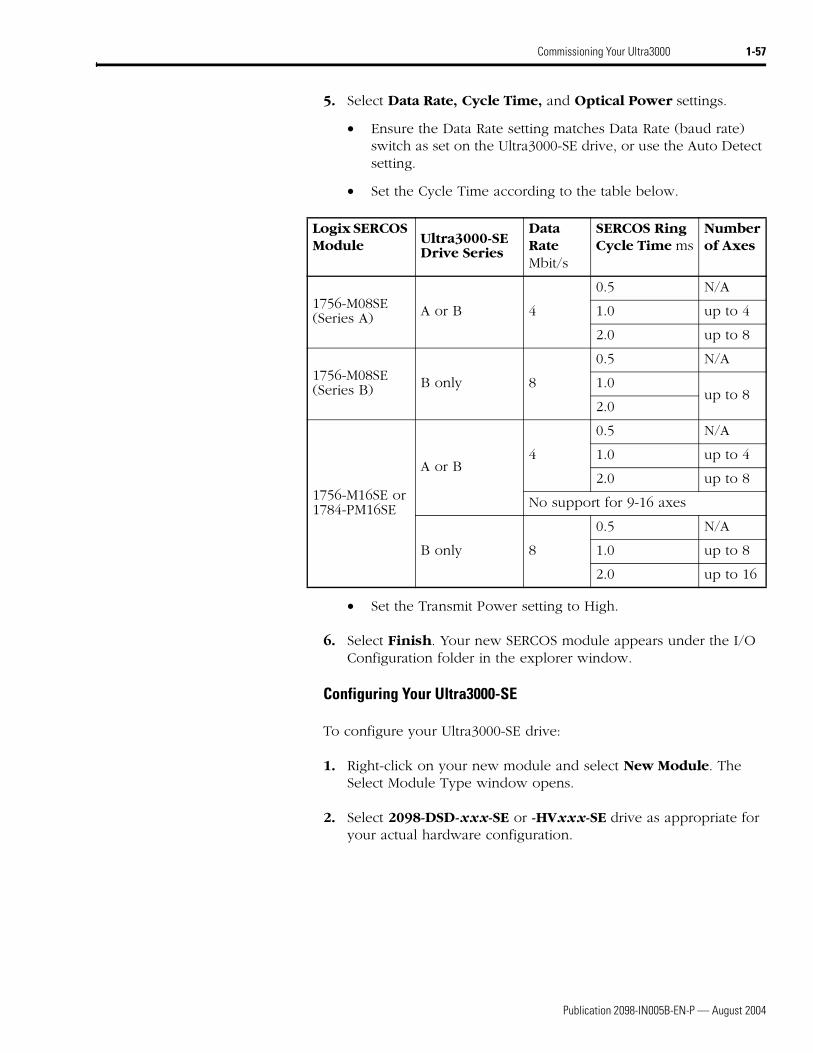
5. Select Data Rate, Cycle Time, and Optical Power settings.
• Ensure the Data Rate setting matches Data Rate (baud rate) switch as set on the Ultra3000-SE drive, or use the Auto Detect setting.
• Set the Cycle Time according to the table below.
• Set the Transmit Power setting to High.
6. Select Finish. Your new SERCOS module appears under the I/O Configuration folder in the explorer window.
Configuring Your Ultra3000-SE
To configure your Ultra3000-SE drive:
1. Right-click on your new module and select New Module. The Select Module Type window opens.
2. Select 2098-DSD-xxx-SE or -HVxxx-SE drive as appropriate for your actual hardware configuration.
Logix SERCOS Module Ultra3000-SE
Drive Series
Data RateMbit/s
SERCOS Ring Cycle Time ms
Number of Axes
1756-M08SE (Series A) A or B 4
0.5 N/A
1.0 up to 4
2.0 up to 8
1756-M08SE (Series B) B only 8
0.5 N/A
1.0up to 8
2.0
1756-M16SE or 1784-PM16SE
A or B4
0.5 N/A
1.0 up to 4
2.0 up to 8
No support for 9-16 axes
B only 8
0.5 N/A
1.0 up to 8
2.0 up to 16
Publication 2098-IN005B-EN-P — August 2004
1-58 Commissioning Your Ultra3000
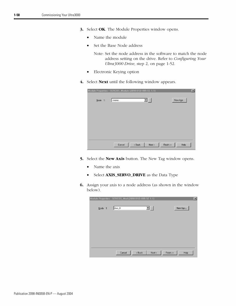
3. Select OK. The Module Properties window opens.
• Name the module
• Set the Base Node address
Note: Set the node address in the software to match the node address setting on the drive. Refer to Configuring Your Ultra3000 Drive, step 2, on page 1-52.
• Electronic Keying option
4. Select Next until the following window appears.
5. Select the New Axis button. The New Tag window opens.
• Name the axis
• Select AXIS_SERVO_DRIVE as the Data Type
6. Assign your axis to a node address (as shown in the window below).
Publication 2098-IN005B-EN-P — August 2004
Commissioning Your Ultra3000 1-59
7. Select Next. Bus Regulator Catalog Number (shunt option) does not apply. Select <none>.
8. Select Finish.
Configuring the Motion Group
To configure the motion group:
1. Right-click Motion Groups in the explorer window and select New Motion Group. The New Tag window opens.
2. Name new motion group.
3. Select OK. New group appears under Motion Group folder.
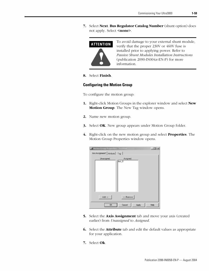
4. Right-click on the new motion group and select Properties. The Motion Group Properties window opens.
5. Select the Axis Assignment tab and move your axis (created earlier) from Unassigned to Assigned.
6. Select the Attribute tab and edit the default values as appropriate for your application.
7. Select Ok.
ATTENTION
!To avoid damage to your external shunt module, verify that the proper 230V or 460V fuse is installed prior to applying power. Refer to Passive Shunt Modules Installation Instructions (publication 2090-IN004x-EN-P) for more information.
Publication 2098-IN005B-EN-P — August 2004
1-60 Commissioning Your Ultra3000
Configuring Axis Properties
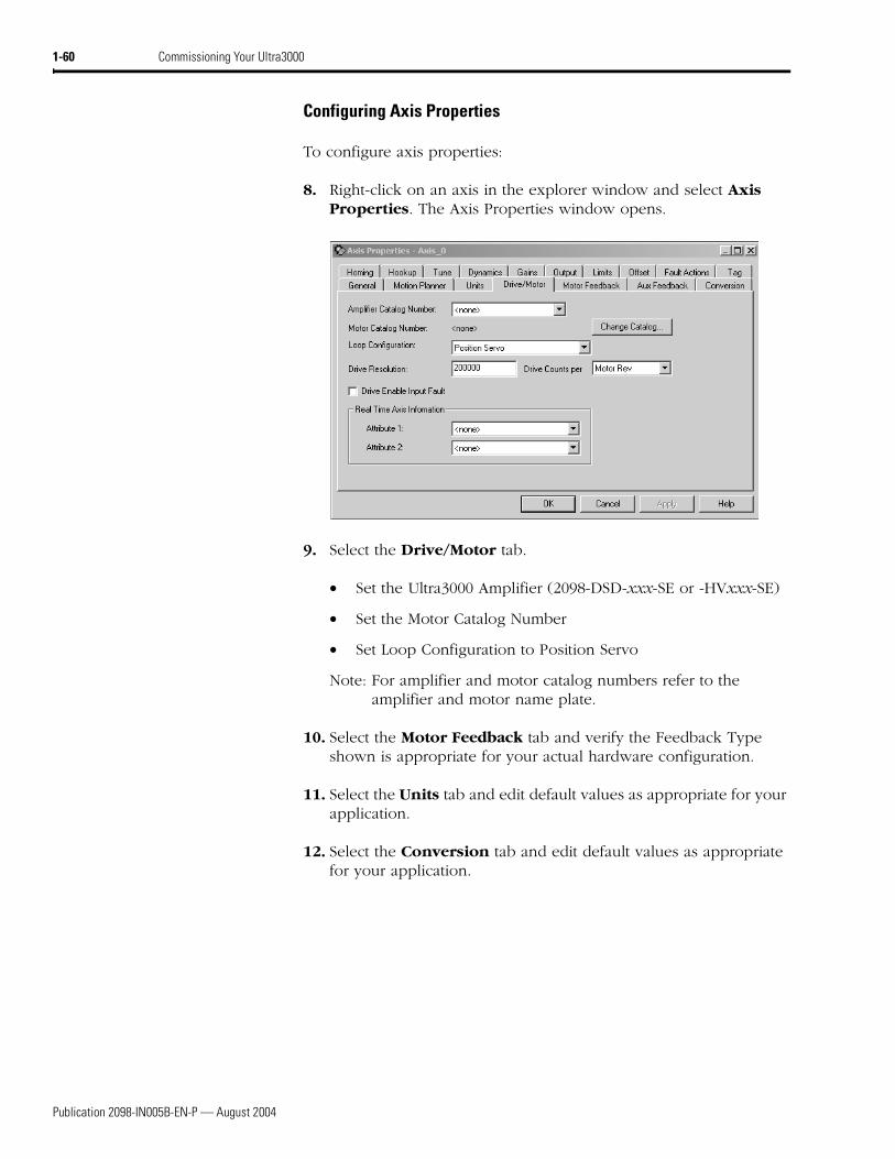
To configure axis properties:
8. Right-click on an axis in the explorer window and select Axis Properties. The Axis Properties window opens.
9. Select the Drive/Motor tab.
• Set the Ultra3000 Amplifier (2098-DSD-xxx-SE or -HVxxx-SE)
• Set the Motor Catalog Number
• Set Loop Configuration to Position Servo
Note: For amplifier and motor catalog numbers refer to the amplifier and motor name plate.
10. Select the Motor Feedback tab and verify the Feedback Type shown is appropriate for your actual hardware configuration.
11. Select the Units tab and edit default values as appropriate for your application.
12. Select the Conversion tab and edit default values as appropriate for your application.
Publication 2098-IN005B-EN-P — August 2004
Commissioning Your Ultra3000 1-61
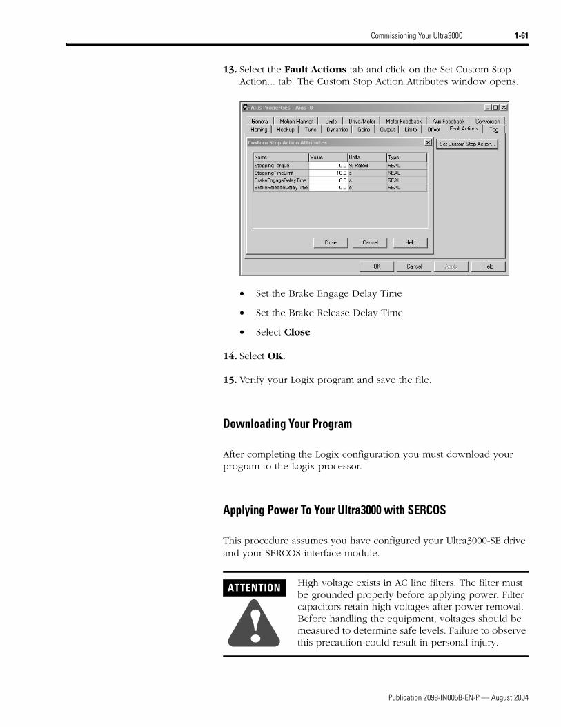
13. Select the Fault Actions tab and click on the Set Custom Stop Action... tab. The Custom Stop Action Attributes window opens.
• Set the Brake Engage Delay Time
• Set the Brake Release Delay Time
• Select Close
14. Select OK.
15. Verify your Logix program and save the file.
Downloading Your Program
After completing the Logix configuration you must download your program to the Logix processor.
Applying Power To Your Ultra3000 with SERCOS
This procedure assumes you have configured your Ultra3000-SE drive and your SERCOS interface module.
ATTENTION
!High voltage exists in AC line filters. The filter must be grounded properly before applying power. Filter capacitors retain high voltages after power removal. Before handling the equipment, voltages should be measured to determine safe levels. Failure to observe this precaution could result in personal injury.
Publication 2098-IN005B-EN-P — August 2004
1-62 Commissioning Your Ultra3000
To apply power to your Ultra3000-SE drive:
1. Disconnect any load to the motor. Ensure the motor is free of all linkages when initially applying power to the system.
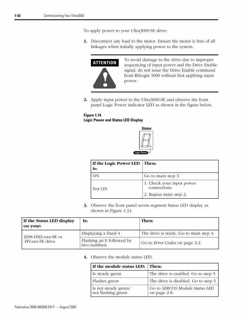
2. Apply input power to the Ultra3000-SE and observe the front panel Logic Power indicator LED as shown in the figure below.
Figure 1.14Logic Power and Status LED Display
3. Observe the front panel seven segment Status LED display as shown in Figure 1.14.
4. Observe the module status LED.
ATTENTION
!To avoid damage to the drive due to improper sequencing of input power and the Drive Enable signal, do not issue the Drive Enable command from RSLogix 5000 without first applying input power.
Status
Logic Power
If the Logic Power LED is:
Then:
ON Go to main step 3.
Not ON1. Check your input power
connections.
2. Repeat main step 2.
If the Status LED display on your:
Is: Then:
2098-DSD-xxx-SE or -HVxxx-SE drive
Displaying a fixed 4 The drive is ready. Go to main step 4.
Flashing an E followed by two numbers Go to Error Codes on page 2-2.
If the module status LED: Then:
Is steady green The drive is enabled. Go to step 5.
Flashes green The drive is disabled. Go to step 5.
Is not steady green/ not flashing green
Go to SERCOS Module Status LED on page 2-8.
Publication 2098-IN005B-EN-P — August 2004
Commissioning Your Ultra3000 1-63
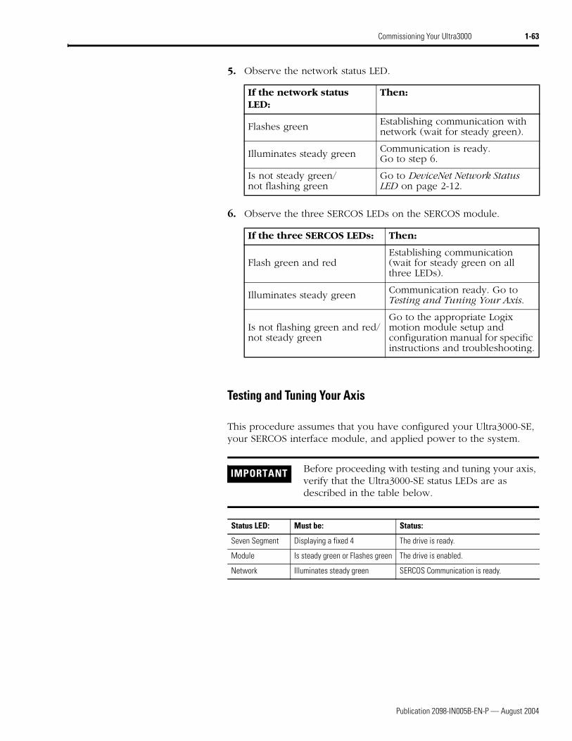
5. Observe the network status LED.
6. Observe the three SERCOS LEDs on the SERCOS module.
Testing and Tuning Your Axis
This procedure assumes that you have configured your Ultra3000-SE, your SERCOS interface module, and applied power to the system.
If the network status LED:
Then:
Flashes green Establishing communication with network (wait for steady green).
Illuminates steady green Communication is ready. Go to step 6.
Is not steady green/ not flashing green
Go to DeviceNet Network Status LED on page 2-12.
If the three SERCOS LEDs: Then:
Flash green and redEstablishing communication (wait for steady green on all three LEDs).
Illuminates steady green Communication ready. Go to Testing and Tuning Your Axis.
Is not flashing green and red/ not steady green
Go to the appropriate Logix motion module setup and configuration manual for specific instructions and troubleshooting.
IMPORTANT Before proceeding with testing and tuning your axis, verify that the Ultra3000-SE status LEDs are as described in the table below.
Status LED: Must be: Status:
Seven Segment Displaying a fixed 4 The drive is ready.
Module Is steady green or Flashes green The drive is enabled.
Network Illuminates steady green SERCOS Communication is ready.
Publication 2098-IN005B-EN-P — August 2004
1-64 Commissioning Your Ultra3000
For greater detail on the RSLogix 5000 software as it applies to ControlLogix and SoftLogix modules, refer to the table below for the appropriate publication.
If you have already tested and tuned your axis using one of the setup and configuration manuals listed above, you are finished commissioning your drive. If not, go to Testing Your Axis beginning below.
Testing Your Axis
To test your axis:
1. Verify the load was removed from your motor(s).
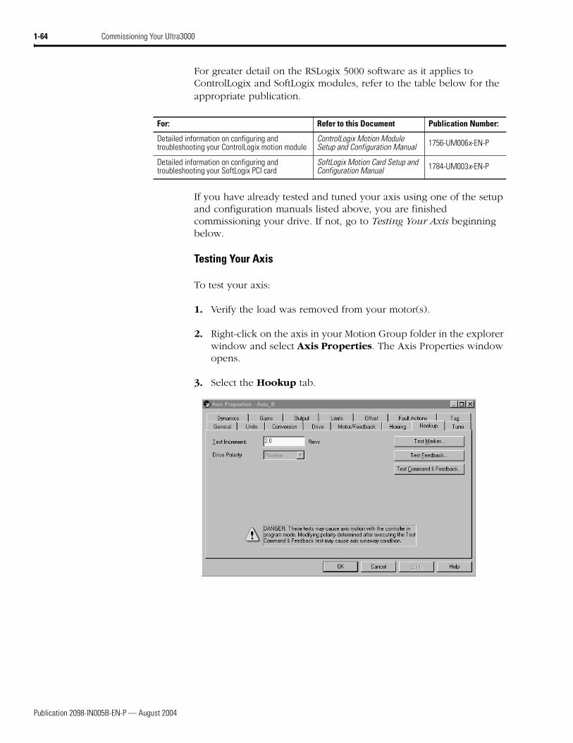
2. Right-click on the axis in your Motion Group folder in the explorer window and select Axis Properties. The Axis Properties window opens.
3. Select the Hookup tab.
For: Refer to this Document Publication Number:
Detailed information on configuring and troubleshooting your ControlLogix motion module
ControlLogix Motion Module Setup and Configuration Manual 1756-UM006x-EN-P
Detailed information on configuring and troubleshooting your SoftLogix PCI card
SoftLogix Motion Card Setup and Configuration Manual 1784-UM003x-EN-P
Publication 2098-IN005B-EN-P — August 2004
Commissioning Your Ultra3000 1-65
4. Select 2.0 as the number of revolutions for the test (or another number more appropriate for your application).
5. Apply Drive Enable (Input 1) signal (CN1-31) for the axis you are testing.
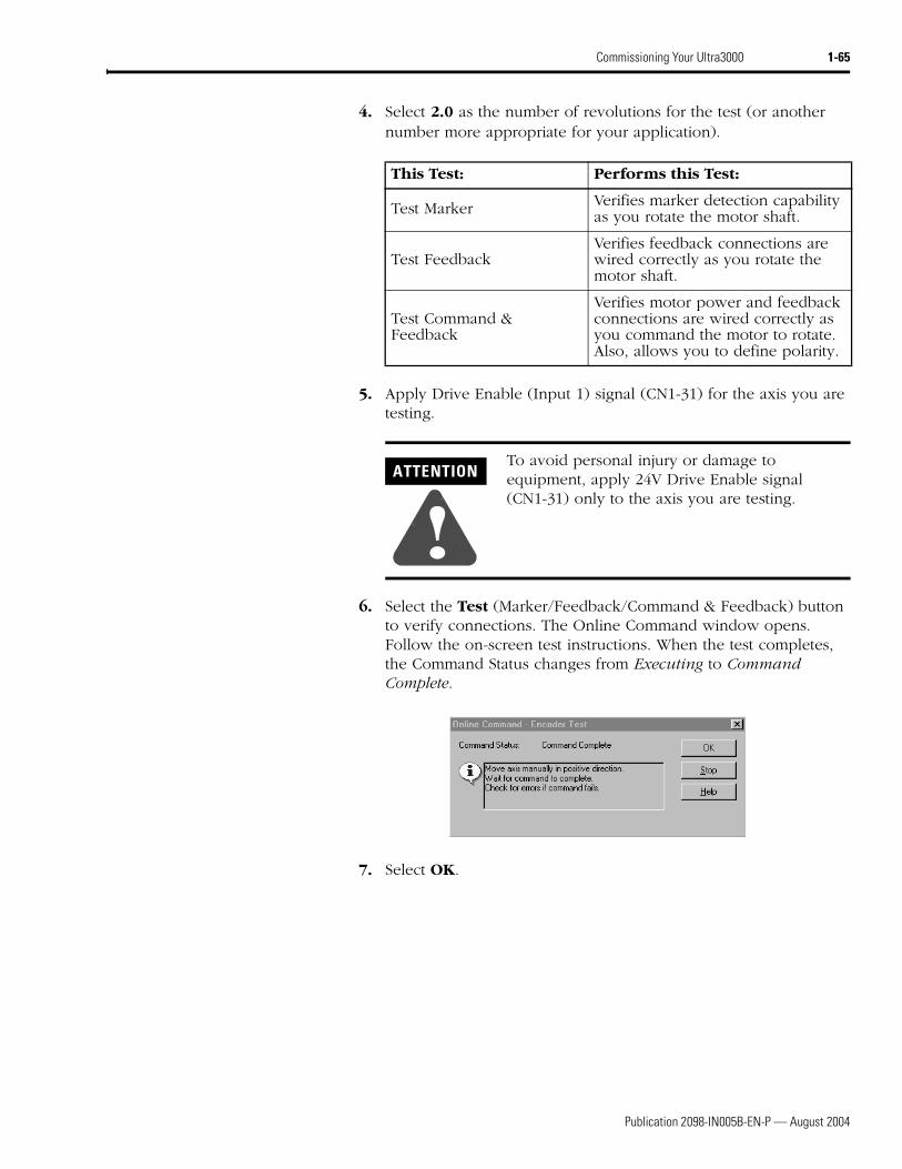
6. Select the Test (Marker/Feedback/Command & Feedback) button to verify connections. The Online Command window opens. Follow the on-screen test instructions. When the test completes, the Command Status changes from Executing to Command Complete.
7. Select OK.
This Test: Performs this Test:
Test Marker Verifies marker detection capability as you rotate the motor shaft.
Test FeedbackVerifies feedback connections are wired correctly as you rotate the motor shaft.
Test Command & Feedback
Verifies motor power and feedback connections are wired correctly as you command the motor to rotate. Also, allows you to define polarity.
ATTENTION
!To avoid personal injury or damage to equipment, apply 24V Drive Enable signal (CN1-31) only to the axis you are testing.
Publication 2098-IN005B-EN-P — August 2004
1-66 Commissioning Your Ultra3000
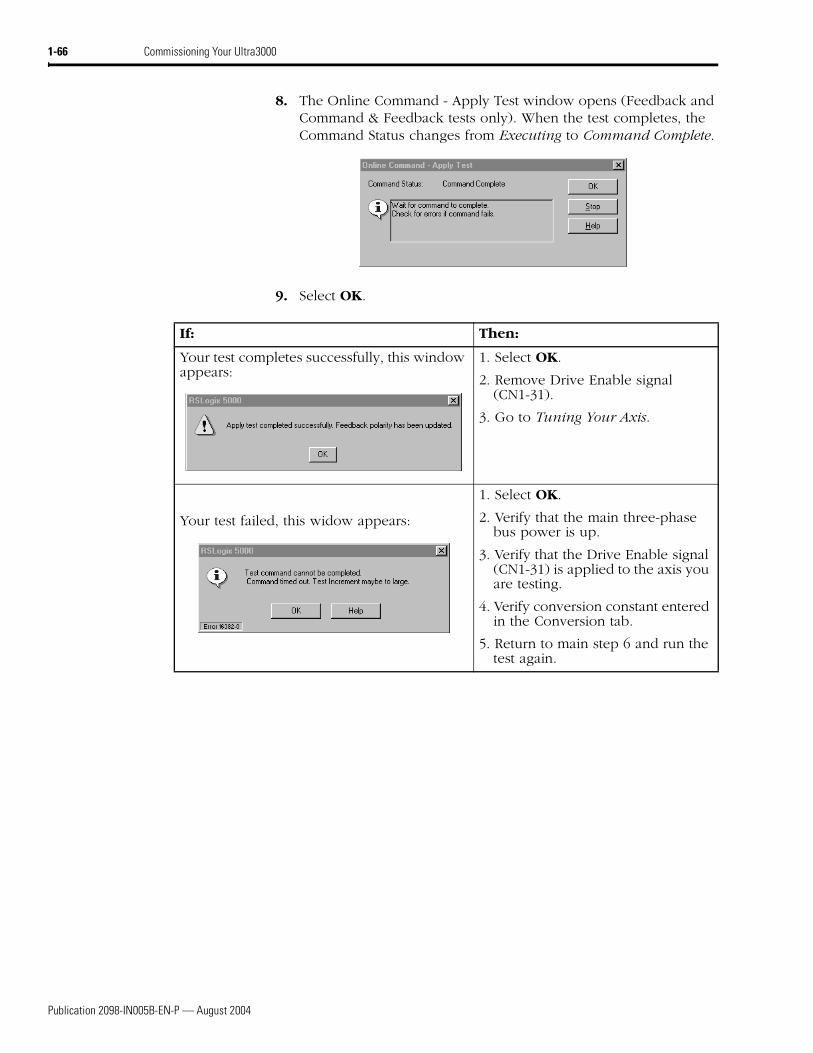
8. The Online Command - Apply Test window opens (Feedback and Command & Feedback tests only). When the test completes, the Command Status changes from Executing to Command Complete.
9. Select OK.
If: Then:
Your test completes successfully, this window appears:
1. Select OK.
2. Remove Drive Enable signal (CN1-31).
3. Go to Tuning Your Axis.
Your test failed, this widow appears:
1. Select OK.
2. Verify that the main three-phase bus power is up.
3. Verify that the Drive Enable signal (CN1-31) is applied to the axis you are testing.
4. Verify conversion constant entered in the Conversion tab.
5. Return to main step 6 and run the test again.
Publication 2098-IN005B-EN-P — August 2004
Commissioning Your Ultra3000 1-67
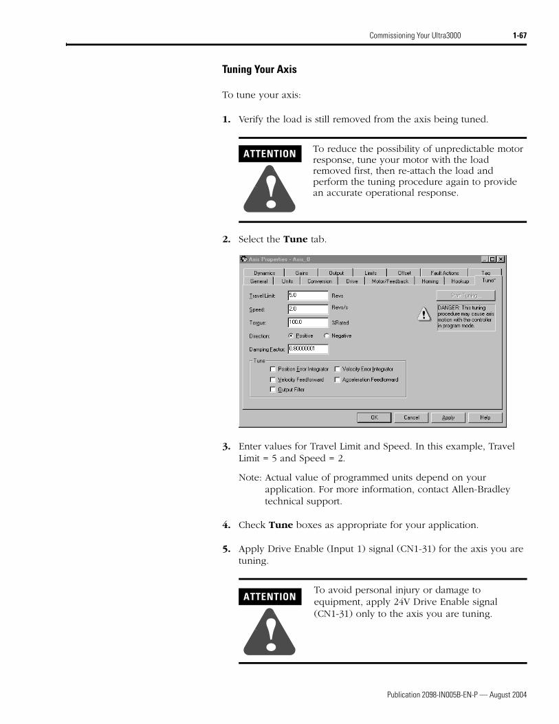
Tuning Your Axis
To tune your axis:
1. Verify the load is still removed from the axis being tuned.
2. Select the Tune tab.
3. Enter values for Travel Limit and Speed. In this example, Travel Limit = 5 and Speed = 2.
Note: Actual value of programmed units depend on your application. For more information, contact Allen-Bradley technical support.
4. Check Tune boxes as appropriate for your application.
5. Apply Drive Enable (Input 1) signal (CN1-31) for the axis you are tuning.
ATTENTION
!To reduce the possibility of unpredictable motor response, tune your motor with the load removed first, then re-attach the load and perform the tuning procedure again to provide an accurate operational response.
ATTENTION
!To avoid personal injury or damage to equipment, apply 24V Drive Enable signal (CN1-31) only to the axis you are tuning.
Publication 2098-IN005B-EN-P — August 2004
1-68 Commissioning Your Ultra3000
6. Select the Start Tuning button to auto-tune your axis. The Online Command - Tune Servo window opens. When the test completes, the Command Status changes from Executing to Command Complete.
7. Select OK. The Tune Bandwidth window opens.
Note: Actual bandwidth values (Hz) depend on your application and may require adjustment once motor and load are connected.
Record your bandwidth data for future reference.
8. Select OK.
9. The Online Command - Apply Tune window opens. When the test completes, the Command Status changes from Executing to Command Complete.
Publication 2098-IN005B-EN-P — August 2004
Commissioning Your Ultra3000 1-69
10. Select OK.
If: Then:
Your test completes successfully, this window appears:
1. Select OK.
2. Remove Drive Enable (Input 1) signal (CN1-31) applied earlier.
3. You are finished tuning your axis.
Your test failed, this widow appears: 1. Select OK.
2. Make an adjustment to motor velocity.
3. Refer to appropriate Logix motion module setup and configuration manual for more information.
4. Return to step 6 and run the test again.
Publication 2098-IN005B-EN-P — August 2004
1-70 Commissioning Your Ultra3000
Configuring Your Ultra3000 with DeviceNet Drive
The procedures in this section apply to Ultra3000-DN drives (2098-DSD-xxx-DN, -xxxX-DN, -HVxxx-DN, and -HVxxxX-DN) and describe how to:
• Configure your Ultra3000-DN drive
• Apply power to your Ultra3000-DN drive
These procedures assume you have completed wiring the DeviceNet interface connector on your Ultra3000-DN drive.
Front Panel Connections
This section provides front panel connection information for your Ultra3000-DN drive.
Use the figure below to locate the front panel connections on the Ultra3000-DN 230V drives (500W, 1 kW, and 2 kW).
Figure 1.15Ultra3000-DN Front Panel Connections for 2098-DSD-005-DN, -005X-DN, -010-DN, -010X-DN, -020-DN, and -020X-DN
For CN1, CN2, and CN3 connector pin-out information, refer to the Ultra3000 Digital Servo Drives Installation Manual (publication 2098-IN003x-EN-P).
Pin 11Pin 6
Pin 15
Pin 1
Pin 10
Pin 5
Pin 30
Pin 44
Pin 1
Pin 15
Pin 16
Pin 31
Pin 6Pin 9
Pin 1
Pin 5
AC Input Power Connections
Motor Power Connections
DC Bus Connections forActive Shunt Resistor Kit
Seven Segment Status LED
Logic Power LED
CN3 9-pin Serial Port Connector
CN2 15-pin Motor Feedback Connector
CN1 44-pin User I/O Connector
DeviceNet InterfaceConnector
Node Address Switches
Data Rate Switch
Module Status LED
Network Status LED
Motor Power Cable Shield Clamp
9-pin CN3Serial Connector
15-pin CN2Feedback Connector
44-pin CN1I/O Connector
Publication 2098-IN005B-EN-P — August 2004
Commissioning Your Ultra3000 1-71
Use the figure below to locate the front panel connections on the Ultra3000-DN 230V drives (3 kW).
Figure 1.16Ultra3000-DN Front Panel Connections for 2098-DSD-030-DN and -030X-DN
For CN1, CN2, and CN3 connector pin-out information, refer to the Ultra3000 Digital Servo Drives Installation Manual (publication 2098-IN003x-EN-P).
U
V
W
+
-
L1
L2/N
L1AUX
L2/NAUX
1
2
3
Motor
DC Bus
100-240 VAC50/60 Hz
Internal
ExternalShunt
TB2
TB1
Pin 11Pin 6
Pin 15
Pin 1
Pin 10
Pin 5
Pin 30
Pin 44
Pin 1
Pin 15
Pin 16
Pin 31
Pin 6Pin 9
Pin 1
Pin 5
V-
Can_L
Shield
Can_H
V+
���������
AC Input Power Connections
Motor Power Connections
Passive Shunt Resistor Connections
Seven Segment Status LED
Logic Power LED
CN3 9-pin Serial Port Connector
CN2 15-pin Motor Feedback Connector
CN1 44-pin User I/O Connector
DeviceNet Interface Connector
Node Address Switches
Data Rate Switch
Module Status LEDNetwork Status LED
Motor Power Cable Shield Clamp
9-pin CN3Serial Connector
15-pin CN2Feedback Connector
44-pin CN1I/O Connector
Publication 2098-IN005B-EN-P — August 2004
1-72 Commissioning Your Ultra3000
Use the figure below to locate the front panel connections on the Ultra3000-DN 230V drives (7.5 and 15 kW).
Figure 1.17Ultra3000-DN Front Panel Connections for 2098-DSD-075-DN, -075X-DN, -150-DN, and -150X-DN
For CN1, CN2, and CN3 connector pin-out information, refer to the Ultra3000 Digital Servo Drives Installation Manual (publication 2098-IN003x-EN-P).
U
V
W
+
-
L1
L2
L3
L1AUX
L2/NAUX
Motor
DC Bus
100-240 VAC50/60 Hz
Internal
ExternalShunt
1
2
3
TB2
TB1
Pin 11Pin 6
Pin 15
Pin 1
Pin 10
Pin 5
Pin 30
Pin 44
Pin 1
Pin 15
Pin 16
Pin 31
Pin 6Pin 9
Pin 1
Pin 5
V-
Can_L
Shield
Can_H
V+
���������
AC Input Power Connections
Motor Power Connections
Passive Shunt Resistor Connections
Seven Segment Status LED
Logic Power LED
CN3 9-pin Serial Port Connector
CN2 15-pin Motor Feedback Connector
CN1 44-pin User I/O Connector
DeviceNet Interface Connector
Node Address Switches
Data Rate Switch
Module Status LEDNetwork Status LED
Motor Power Cable Shield Clamp
9-pin CN3Serial Connector
15-pin CN2Feedback Connector
44-pin CN1I/O Connector
Publication 2098-IN005B-EN-P — August 2004
Commissioning Your Ultra3000 1-73
Use the figure below to locate the front panel connections on the Ultra3000-DN 460V drives (3 kW, 5 kW, 10 kW, 15 kW, and 22 kW).
Figure 1.18Ultra3000-DN Front Panel Connections for 2098-DSD-HVxxx-DN and HVxxxX-DN
For CN1, CN2, and CN3 connector pin-out information, refer to the Ultra3000 Digital Servo Drives Installation Manual (publication 2098-IN003x-EN-P).
W
V
U
+
-
L3
L2
L1
L1AUX
L2AUX
Mot
orDC
Bus
230-
480
VAC
50/6
0 Hz
Inte
rnal
Exte
rnal
Shu
nt 1
2
3
Can_H
V+
TB2
DANGERDANGERHazardous voltageexists after power down.
TB1
500kB
250kB
125kB
AUTOPGM
V-
Can_L
Shield
(00-63, PGM)
���������
Pin 11Pin 6
Pin 15
Pin 1
Pin 10
Pin 5
Pin 30
Pin 44
Pin 1
Pin 15
Pin 16
Pin 31
Pin 6Pin 9
Pin 1
Pin 5
AC Input Power Connections
Motor Power Connections
Passive Shunt Resistor Connections
Seven Segment Status LED
Logic Power LED
CN3 9-pin Serial Port Connector
CN2 15-pin Motor Feedback Connector
CN1 44-pin User I/O Connector
DeviceNet Interface Connector
Node Address Switches
Data Rate Switch
Module Status LEDNetwork Status LED
Motor Power Cable Shield Clamp
9-pin CN3Serial Connector
15-pin CN2Feedback Connector
44-pin CN1I/O Connector
Publication 2098-IN005B-EN-P — August 2004
1-74 Commissioning Your Ultra3000
Configuring Your Ultra3000 with DeviceNet
Use the following procedures to configure your Ultra3000-DN drive (2098-DSD-xxx-DN, -xxxX-DN, -HVxxx-DN, and -HVxxxX-DN) using Ultraware software and apply power to the drive.
To configure your Ultra3000-DN drive:
1. Verify that there is no power applied to the drive, and the DeviceNet cable is connected (refer to figures 1.15-1.18 for the connector location).
2. Set the node address for each drive in your system. Valid node addresses are 00-63 and PGM. The MSD rotary switch sets the most significant digit and the LSD rotary switch sets the least significant digit. Refer to figures 1.15-1.18 for the switch locations. Refer to the table below for examples.
Note: Selecting an invalid node address (> 63) sets the node address according to a non-volatile parameter stored in the drive.
3. Set the data rate. Valid data rates are 125 kps, 250 kps, 500 kps, AUTO, and PGM. Refer to figures 1.15-1.18 for the switch location.
Note: Selecting AUTO automatically matches the device data rate to the rate of the network. Selecting PGM sets the data rate according to a non-volatile parameter stored in the drive.
For this Node Address:
Set the MSD switch to:
Set the LSD switch to:
10 1 0
11 1 1
12 1 2
Use the MSD and LSD rotary switches on the DeviceNet panel of the drive to set node addresses.
Use the Data Rate rotary switch on the DeviceNet panel of the drive to set the data rate.
Publication 2098-IN005B-EN-P — August 2004
Commissioning Your Ultra3000 1-75
Applying Power To Your Ultra3000 with DeviceNet
This procedure assumes you have wired your Ultra3000-DN system, verified the wiring, and are ready to begin using your Ultraware software.
To apply power to your Ultra3000-DN drive:
1. Disconnect any load to the motor. Ensure the motor is free of all linkages when initially applying power to the system.
2. Apply input power to the Ultra3000-DN and observe the front panel Logic Power indicator LED as shown in the figure below.
Figure 1.19Logic Power and Status LED Display
ATTENTION
!High voltage exists in AC line filters. The filter must be grounded properly before applying power. Filter capacitors retain high voltages after power removal. Before handling the equipment, voltages should be measured to determine safe levels. Failure to observe this precaution could result in personal injury.
ATTENTION
!To avoid damage to the drive due to improper sequencing of input power and the Drive Enable signal, you must assign one of the eight inputs as Drive Enable (Input 1 is the default setting).
Status
Logic Power
If the Logic Power LED is: Then:
ON Go to main step 3.
Not ON1. Check your input power
connections.
2. Repeat main step 2.
Publication 2098-IN005B-EN-P — August 2004
1-76 Commissioning Your Ultra3000
3. Observe the front panel seven segment Status LED display as shown in Figure 1.19.
4. Observe the module status LED.
5. Observe the network status LED.
6. For further commissioning procedures, refer to the following sections beginning on page 1-8.
• Detecting Your Ultra3000 Drive
• Understanding the Workspace and Drive Branches
• Selecting a Motor
• Tuning Your Motor
• Testing Your Motor (Non-Indexing Move)
• Testing Your Motor (Indexing Move)
• Indexing and Non-Indexing Move Examples
Refer to the Ultra3000 with DeviceNet Reference Manual (publication 2098-RM001x-EN-P) for information on communicating to the Ultra3000 using DeviceNet.
If the Status LED display on your:
Is: Then:
2098-DSD-xxx-DN, -xxxX-DN, -HVxxx-DN, or HV-xxxX-DN drive
Actively cycling segments in a full circle The drive is ready. Go to step 4.
Flashing an E followed by two numbers Go to Error Codes on page 2-2.
If the module status LED: Then:
Is steady green The drive is ready. Go to step 5.
Is not steady green Go to SERCOS Module Status LED on page 2-8.
If the network status LED: Then:
Is off
Establishing communication with network (wait for flashing or steady green).
Is flashing or steady green Communication is ready. Go to step 6.
Is not flashing or steady green Go to DeviceNet Network Status LED on page 2-12.
1 Publication 2098-IN005B-EN-P — August 2004
Chapter 2
Troubleshooting Your Ultra3000
Chapter Objectives This chapter provides a description of maintenance and troubleshooting activities for the Ultra3000. This chapter includes these sections:
• Safety Precautions
• General Troubleshooting
• Troubleshooting for SERCOS Drives
• Troubleshooting for DeviceNet Drives
Safety Precautions Observe the following safety precautions when troubleshooting your Ultra3000 drive.
ATTENTION
!DC bus capacitors may retain hazardous voltages after input power has been removed. Before working on the drive, measure the DC bus voltage to verify it has reached a safe level or wait the full time interval listed on the drive warning label. Failure to observe this precaution could result in severe bodily injury or loss of life.
Do not attempt to defeat or override the drive fault circuits. You must determine the cause of a fault and correct it before you attempt to operate the system. If you do not correct a drive or system malfunction, it could result in personal injury and/or damage to the equipment as a result of uncontrolled machine system operation.
Test equipment (such as an oscilloscope or chart recorder) must be properly grounded. Failure to include an earth ground connection could result in a potentially fatal voltage on the oscilloscope chassis.
Publication 2098-IN005B-EN-P — August 2004
2-2 Troubleshooting Your Ultra3000
General Troubleshooting Refer to the Error Codes section below to identify problems, potential causes, and appropriate actions to resolve the problems. If problems persist after attempting to troubleshoot the system, please contact your Allen-Bradley representative for further assistance. To determine if your Ultra3000 drive has an error, refer to the table below.
Error Codes
The following list of problematic symptoms (no error code shown) and problems with assigned error codes is designed to help you resolve problems.
When a fault is detected, the seven-segment LED will display an E followed by the flashing of the two-digit error code, one digit at a time. This is repeated until the problem is cleared.
If the Logic Power LED is ON and the Status LED display on your: Is: Then:
2098-DSD-xxx, -xxxX, -HVxxx, or -HVxxxX drive
Actively cycling segments in a full circleYour Ultra3000 drive is ready.
2098-DSD-xxx-DN, -xxxX-DN, -HVxxx-DN, -HVxxxX-DN drive Your Ultra3000 drive is ready.
2098-DSD-xxx-SE or -HVxxx-SE drive Displaying a fixed 4 Your Ultra3000 drive is ready.
All drivesFlashing E followed by two numbers Your Ultra3000 drive has an error. Proceed to
the section Error Codes below.
Flashing L Your Ultra3000 drive is in an Overtravel condition and motion restrictions are in effect.
Error Code Problem or Symptom Possible Cause(s) Action/Solution
Power (PWR) indicator not ONNo AC power or auxiliary logic power. Verify AC power or auxiliary +5V logic
power is applied to the Ultra3000.
Internal power supply malfunction. Call your Allen-Bradley representative.
Power (PWR) indicator is ON, but seven segment Status LED display is OFF. Note: This applies to 2098-DSD-005, -010, and -020 Ultra3000 models only.
Externally applied +5V auxiliary power supply voltage is too low.
Verify that the external +5V auxiliary power supply (as measured at the drive terminals) reads between 5.10V and 5.25V.
Motor jumps when first enabledMotor wiring error. Check motor wiring.
Incorrect motor chosen. Verify the proper motor is selected.
Digital I/O not working correctly I/O power supply disconnected. Verify connections and I/O power source.
E01 Non-Volatile Memory Endurance ExceededRange of motion and number of home position definitions during the product life exceeds the maximum allowed (applies only to systems with absolute feedback).
This is an unrecoverable fault, the drive must be sent back to the factory.
E02 Velocity Exceeds Position Rollover /2
The velocity command or feedback exceeds half the machine cycle length per millisecond (applies only when the machine cycle position rollover is enabled).
Increase machine cycle size or reduce velocity profile. This error only applies to firmware versions prior to 1.10.
Publication 2098-IN005B-EN-P — August 2004
Troubleshooting Your Ultra3000 2-3
E03 Absolute Feedback Range ExceededThe motor position exceeds +/- 2047 revolutions from the home position (applies only to systems with absolute feedback).
• Decrease application range of motion.
• Upgrade firmware.
E04 Motor Overtemperature
Motor thermostat trips due to:• High motor ambient temperature
and/or
• Excessive current
• Operate within (not above) the continuous torque rating for the ambient temperature (40°C maximum).
• Lower ambient temperature, increase motor cooling.
Motor wiring error. Check motor wiring.
Incorrect motor selection. Verify the proper motor has been selected.
E05 IPM Fault
Motor cables shorted. Verify continuity of motor power cable and connector.
Motor winding shorted internally.Disconnect motor power cables from the motor. If the motor is difficult to turn by hand, it may need to be replaced.
Ultra3000 temperature too high.
• Check for clogged vents or defective fan.
• Ensure cooling is not restricted by insufficient space around the unit.
Operation above continuous power rating.
• Verify ambient temperature is not too high.
• Operate within the continuous power rating.
• Reduce acceleration rates.
Ultra3000 has a bad IPM output, short circuit, or overcurrent.
Remove all power and motor connections, and preform a continuity check from the DC bus to the U, V, and W motor outputs. If a continuity exists, check for wire fibers between terminals, or send drive in for repair.
An attempt was made to enable the drive without waiting at least 1.0 second after applying the main AC power. Note: This applies to 2098-DSD-005, -010, and -020 Ultra3000 models only (when using an external +5V auxiliary power supply).
Wait at least 1.0 second after the main AC is applied before enabling the drive.
E06 Hardware Overtravel(SERCOS only) Dedicated overtravel input is inactive.
• Check wiring.
• Verify motion profile.
E07 RESERVED Call your local Allen-Bradley representative.E08 RESERVED
E09 Bus Undervoltage Low AC line/AC power input.
• Verify voltage level of the incoming AC power.
• Check AC power source for glitches or line drop.
• Install an uninterruptible power supply (UPS) on your AC input.
Error Code Problem or Symptom Possible Cause(s) Action/Solution
Publication 2098-IN005B-EN-P — August 2004
2-4 Troubleshooting Your Ultra3000
E10 Bus Overvoltage
Excessive regeneration of power. When the motor is driven by an external mechanical power source, it may regenerate too much peak energy through the Ultra3000’s power supply. The system faults to save itself from an overload.
• Change the deceleration or motion profile.
• Use a larger system (motor and Ultra3000).
• Use a resistive shunt.
• If a shunt is connected, verify the wiring is correct and shunt fuse is not blown.
Excessive AC input voltage. Verify input is within specifications.
E11 Illegal Hall State
Incorrect phasing. Check the Hall phasing.
Bad connections.• Verify the Hall wiring.
• Verify 5V power supply to the encoder.
E12 Home Search Failed Home sensor and/or marker is outside the overtravel limits.
• Check wiring.
• Reposition the overtravel limits or sensor.
E13 Home Position In LimitHome sensor, marker, or final home position exceeds a hardware overtravel limit.
• Reposition the overtravel limits or home sensor.
• Adjust the final home position.
E14
SERCOS Hardware Fault (SERCOS drives only)
A fault was detected with the operation of the drive’s internal SERCOS hardware.
Contact your local Allen-Bradley representative.
DeviceNet Communications Network problem (DeviceNet drives only)
DeviceNet communications network is broken Troubleshoot DeviceNet communications.
E15 Excessive Electrical Cycle Length Electrical cycle length exceeds maximum lines per electrical cycle Replace the linear motor/encoder.
E16 Software Overtravel(SERCOS only)
Programmed overtravel limit has been exceeded.
• Verify motion profile.
• Verify overtravel settings are appropriate.
E17 User-Specified Current Fault User-Specified average current level has been exceeded. Increase to a less restrictive setting.
E18 Overspeed Fault Motor speed has exceeded 125% of maximum rated speed.
• Check cables for noise.
• Check tuning.
E19 Excess Position Error Position error limit was exceeded.
• Increase the feedforward gain.
• Increase following error limit or time.
• Check position loop tuning.
Error Code Problem or Symptom Possible Cause(s) Action/Solution
Publication 2098-IN005B-EN-P — August 2004
Troubleshooting Your Ultra3000 2-5
E20 Motor Encoder State ErrorThe motor encoder encountered an illegal transition.
• Replace the motor/encoder.
• Use shielded cables with twisted pair wires.
• Route the feedback away from potential noise sources.
• Check the system grounds.
• Verify that the unbuffered encoder signals are not subjected to EMI in the CN1 cable. Remove these signals from the CN1 cable if they are not being used.
• Verify that the motor has a high-frequency bond to the drive’s enclosure panel.
• Verify that any stage connected to the motor shaft (for example using a ball screw) has a high-frequency bond to the machine frame and the drive’s enclosure panel.
Bad encoder. Replace motor/encoder.
E21 Auxiliary Encoder state error
The auxiliary encoder encountered an illegal transition.
• Use shielded cables with twisted pair wires.
• Route the encoder cable away from potential noise sources.
• Bad encoder - replace encoder.
• Check the ground connections.
Setup time violation for Step/Direction or CW/CCW input.
Check timing of Step/Direction or CW/CCW inputs to determine if setup time requirements are being met.
E22 Motor Thermal Protection Fault The internal filter protecting the motor from overheating has tripped.
• Reduce acceleration rates.
• Reduce duty cycle (ON/OFF) of commanded motion.
• Increase time permitted for motion.
• Use larger Ultra3000 and motor.
• Check tuning.
E23 IPM Thermal Protection Fault The internal filter protecting the drive from over heating has tripped.
• Reduce acceleration rates.
• Reduce duty cycle (ON/OFF) of commanded motion.
• Increase time permitted for motion.
• Use larger Ultra3000 and motor.
• Check tuning.
E24 Excess Velocity Error Velocity error limit was exceeded.
• Increase time or size of allowable error.
• Reduce acceleration.
• Check tuning.
E25 Sensor Not Assigned Homing or registration motion was attempted without a sensor assigned. Assign a sensor to a digital input.
E26 User-Specified Velocity Fault User specified velocity level was exceeded. Increase to a less restrictive setting.
E27 Axis Not Homed Absolute positioning was attempted without homing. Verify homing sequence.
Error Code Problem or Symptom Possible Cause(s) Action/Solution
Publication 2098-IN005B-EN-P — August 2004
2-6 Troubleshooting Your Ultra3000
E28 Motor Parameter ErrorParameter loaded from smart encoder or received from SERCOS controller is incompatible with the drive.
• Select a different motor through the SERCOS controller.
• Select a different motor.
E29 Encoder Output Frequency Exceeded
Encoder output frequency exceeds the maximum user specified value. This only applies when the encoder output is synthesized by the drive.
• Increase the encoder output maximum frequency parameter.
• Decrease the encoder interpolation parameter.
• Increase the encoder output divider parameter.
E30 Encoder Communication Fault Communication was not established with an intelligent encoder.
• Verify motor selection.
• Verify the motor supports automatic identification.
• Verify motor encoder wiring.
E31 Encoder Data Encoder data is corrupted. Replace the motor/encoder.
E32 Sine/Cosine Encoder Frequency Limit Exceeded
Maximum frequency of the sine/cosine circuitry has been exceeded.
• Decrease velocity.
• Use encoder with lower resolution (before interpolation).
E33 Absolute Position Exceeds Position Rollover
Motion is commanded to a position outside the position rollover range.• An absolute index is initiated that
specifies a position outside the position rollover range.
• A homing cycle is initiated with the home position outside the position rollover range.
• A define home is initiated with the home position outside the position rollover range.
• A preset position is initiated that specifies a position outside the position rollover range.
Set motion command to a position within the position rollover range.
E34 Ground Fault
Wiring error. Check motor power wiring.
Motor internal ground short. Replace motor.
Internal malfunction.
Disconnect motor power cable from drive and enable drive with current limit set to 0. If fault remains, call your Allen-Bradley representative. If fault clears, then a wiring error or motor internal problem exists.
E35 Precharge FaultLow AC input voltage. Check input AC voltage on all phases.
Internal malfunction. Call your Allen-Bradley representative.
E36 Power Circuitry Overtemperature Excessive heat exists in the power circuitry.
• Reduce acceleration rates.
• Reduce duty cycle (ON/OFF) of commanded motion.
• Increase time permitted for motion.
• Use larger Ultra3000 and motor.
• Check tuning.
E37 AC Line Loss One or more phases of the input AC power is missing. Check input AC voltage on all phases.
E38 RESERVED Call your local Allen-Bradley representative.
Error Code Problem or Symptom Possible Cause(s) Action/Solution
Publication 2098-IN005B-EN-P — August 2004
Troubleshooting Your Ultra3000 2-7
E39 Self-sensing Commutation Startup Error Motion required for self-sensing startup commutation was obstructed.
• Verify that there are no impediments to motion at startup, such as hard limits.
• Increase self-sensing current if high friction or load conditions exist.
• Check motor or encoder wiring using wiring diagnostics.
E40 230V Shunt Protection FaultIneffective shunt resistor • Verify that the shunt resistor (internal or
external) is connected.
• If an external shunt resistor is connected, verify that the shunt fuse is not blown.
• If a non Allen-Bradley external shunt resistor is used, verify that the resistance value is within specifications.
• Verify that the motor is not being driven mechanically, causing the motor to behave as a generator.
Excessive regeneration
E41 460V Shunt Protection Fault
Ineffective shunt resistor
Excessive regeneration
E42 Motor Keying Error (SERCOS drives only)The motor physically connected to the drive differs from the motor specified in the user program.
Select the correct motor in the user program.
E43 Drive Enable Input (SERCOS drives only)
• An attempt was made to enable the axis through software while the Drive Enable hardware input was inactive.
• The Drive Enable input transitioned from active to inactive while the axis was enabled.
• Disable the Drive Enable Input fault.
• Verify that Drive Enable hardware input is active whenever the drive is enabled through software.
E50 Duplicate Node Fault (SERCOS drives only)
Duplicate node address detected on SERCOS ring.
Verify that each SERCOS drive is assigned a unique node address.
All others RESERVED Call your local Allen-Bradley representative.
Error Code Problem or Symptom Possible Cause(s) Action/Solution
Publication 2098-IN005B-EN-P — August 2004
2-8 Troubleshooting Your Ultra3000
Troubleshooting for SERCOS Drives
SERCOS Module Status LED
Use the table below for troubleshooting the SERCOS Module Status LED on your Ultra3000 (2098-DSD-xxx-SE or -HVxxx-SE).
SERCOS Network Status LED
Use the table below for troubleshooting the SERCOS Network Status LED on your Ultra3000 (2098-DSD-xxx-SE or -HVxxx-SE).
1 Refer to Fiber Optic Cable Installation and Handling Instructions (publication 2090-IN010x-EN-P) for more information.
If the SERCOS Module Status LED is:
Status is: Potential Cause is: Possible Resolution is:
Steady Green Normal Drive is enabled. Normal operation when drive is enabled.
Flashing Green Standby Drive is not enabled. Normal operation when drive is disabled.
Flashing Red-Green DC Bus Undervoltage The DC bus voltage is low.
• Normal operation when using auxiliary power (main AC power is not applied).
• When using main AC power, refer to the section Error Codes to continue troubleshooting.
Flashing Red Minor fault Drive is faulted, but the fault can be cleared. Refer to the section Error Codes to continue troubleshooting.
Steady Red Unrecoverable fault Drive is faulted, and the fault cannot be cleared.
Contact your local Allen-Bradley representative.
If the SERCOS Network Status LED is:
Status is: Potential Cause is: Possible Resolution is:
Steady Green Communication ready No faults or failures. N/A
Flashing Green Establishing communication
System is still in the process of establishing SERCOS communication. Wait for steady green LED status.
Node address setting on the drive module does not match SERCOS controller configuration.
This section provides the Ultra3000-SE drive fault actions and indicates whether the fault action is programmable.
The following drive fault action definitions apply:
When a fault is detected, the seven-segment LED will display an E followed by the flashing of the two-digit error code, one digit at a time. This is repeated until the problem is cleared.
Drive Fault Action Definition
Disable Drive The drive is disabled. Uncontrolled Stop, motor coasts to a stop.
E01Range of motion and number of home position definitions during the product life exceeds the maximum allowed (applies only to systems with absolute feedback).
DISABLE NO
DriveHardFault(Velocity Exceeds Position Rollover /2)
E02The velocity command or feedback exceeds half the machine cycle length per millisecond (applies only when the machine cycle position rollover is enabled).
DISABLE NO
DriveHardFault(Absolute Feedback Range Exceeded)
E03 The motor position exceeds +/- 2047 revolutions from the home position (applies only to systems with absolute feedback). DISABLE NO
MotorOvertempFault(Motor Overtemperature)
E04 The motor thermal switch was tripped. DISABLE YES
DriveHardFault(IPM Fault)
E05A problem in the drive power structure was detected. Motor cables shorted, motor winding shorted internally, temperature too high, operation above continuous power rating, or has a bad IPM output, short circuit, or overcurrent.
DISABLE NO
HardOvertravelFault(+/- Hard Overtravel)
E06 Axis moved beyond the physical travel limits in the positive/negative direction. This fault can be configured for status only. DISABLE YES
MotFeedbackFault(Channel BM Line Loss)
E07 The feedback wiring is open, shorted or missing. DISABLE NO
MotFeedbackFault(Channel AM Line Loss)
E08 The feedback wiring is open, shorted or missing. DISABLE NO
DriveUndervoltageFault(Bus Undervoltage)
E09 With 3 phase present, the DC bus voltage is below limits. The trip point if 275V and 137V DC for 460V/230V drives respectively. DISABLE NO
DriveOvervoltageFault(Bus Overvoltage)
E10 The DC bus voltage is above limits. The trip point is 820V and 410V dc for 460V/230V drives respectively. DISABLE NO
CommutationFault(Illegal Hall State)
E11 State of Hall inputs is incorrect. DISABLE NO
DriveHardFault(Home Search Failed)
E12 Home sensor and/or marker is outside the overtravel limits. DISABLE NO
DriveHardFault(Home Position In Limit)
E13 Home sensor, marker, or final home position exceeds a hardware overtravel limit. DISABLE NO
Publication 2098-IN005B-EN-P — August 2004
2-10 Troubleshooting Your Ultra3000
SERCOSFault(SERCOS or DeviceNet Communications Network problem)
E14 SERCOS or DeviceNet communications network is broken DISABLE NO
DriveHardFault(Excessive Electrical Cycle Length)
E15 Configuration information is not valid. N/A NO
SoftOvertravelFault(+/- Software Overtravel)
E16 Programmed positive/negative overtravel limit has been exceeded. DISABLE YES
DriveHardFault(User-Specified Current Fault)
E17 User-Specified average current level has been exceeded. DISABLE NO
OverspeedFault(Overspeed Fault)
E18 Motor speed has exceeded 125% of maximum rated speed. DISABLE NO
PositionErrorFault(Excess Position Error)
E19 Axis position error limit has been exceeded. This fault can be configured for status only. DISABLE YES
MotFeedbackFault(Motor Encoder State Error)
E20 The motor encoder encountered an illegal transition. DISABLE NO
AuxFeedbackNoiseFault(Auxiliary Encoder State Error)
E21 The auxiliary encoder encountered an illegal transition. DISABLE NO
OverloadFault(Motor Thermal Protection Fault)
E22 The internal filter protecting the motor from overheating has tripped. DISABLE YES
DriveOvertempFault(IPM Thermal Protection Fault)
E23 The internal filter protecting the drive from over heating has tripped. DISABLE YES
DriveHardFault(Excess Velocity Error)
E24 Velocity error limit was exceeded. DISABLE NO
DriveHardFault(Sensor Not Assigned)
E25 Homing or registration motion was attempted without a sensor assigned. DISABLE NO
DriveHardFault(User-Specified Velocity Fault)
E26 User specified velocity level was exceeded. DISABLE NO
DriveHardFault(Axis Not Homed)
E27 Absolute positioning was attempted without homing. DISABLE NO
DriveHardFault(Motor Parameter Error)
E28 Parameter loaded from smart encoder or received from SERCOS controller is incompatible with the drive. DISABLE NO
DriveHardFault(Encoder Output Frequency Exceeded)
E29Encoder output frequency exceeds the maximum user specified value. This only applies when the encoder output is synthesized by the drive.
DISABLE NO
DriveHardFault(Encoder Communication Fault)
E30 Communication was not established with an intelligent (i.e. Stegmann) encoder on the motor feedback port. DISABLE NO
DriveHardFault(Encoder Data)
E31 Encoder data is corrupted. DISABLE NO
Fault Message RSLogix(Ultraware)
Error Code Description Drive Fault
ActionRSLogix Programmable Fault Action?
Publication 2098-IN005B-EN-P — August 2004
Troubleshooting Your Ultra3000 2-11
DriveHardFault(Sine/Cosine Encoder Frequency Limit Exceeded)
E32 Maximum frequency of the sine/cosine circuitry has been exceeded. DISABLE NO
DriveHardFault(Absolute Position Exceeds Position Rollover)
E33 Absolute position exceeds position rollover. DISABLE NO
DriveHardFault(Ground Fault)
E34 Excessive ground current in the converter was detected. DISABLE NO
DriveHardFault(Precharge Fault)
E35 The converter pre-charge cycle has failed. DISABLE NO
DriveHardFault(Power Circuitry Overtemperature)
E36 Excessive heat exists in the power circuitry. DISABLE NO
DriveHardFault(AC Line Loss)
E37 One or more phases of the input AC power is missing. DISABLE NO
SERCOSFault(SERCOS Ring Fault)
E38 The SERCOS ring is not active after being active and operational. DISABLE NO
E39 Self-sense commutation fault detected DISABLE NO
DriveHardFault(230V Shunt Protection Fault)
E40 Ineffective shunt resistor DISABLE NO
DriveHardFault(460V Shunt Protection Fault)
E41 Ineffective shunt resistor DISABLE NO
ConfigFault(Motor Keying Error)
E42 The motor physically connected to the drive differs from the motor specified in the user program. N/A NO
DriveEnableInputFault(Drive Enable Input)
E43 Generated when Enable input switches off when drive is enabled. DISABLE YES
SERCOSFault(Duplicate Node Fault)
E50 Duplicate node address detected on SERCOS ring. DISABLE NO
RESERVED All Others
Fault Message RSLogix(Ultraware)
Error Code Description Drive Fault
ActionRSLogix Programmable Fault Action?
Publication 2098-IN005B-EN-P — August 2004
2-12 Troubleshooting Your Ultra3000
Troubleshooting for DeviceNet Drives
DeviceNet Module Status LED
Use the table below for troubleshooting the DeviceNet Module Status LED on your Ultra3000 (2098-DSD-xxx-DN, -xxxX-DN, -HVxxx-DN, or -HVxxxX-DN).
DeviceNet Network Status LED
Use the table below for troubleshooting the DeviceNet Network Status LED on your Ultra3000 (2098-DSD-xxx-DN, -xxxX-DN, -HVxxx-DN, or -HVxxxX-DN).
If the Module Status LED is: Status is: Potential Cause is: Possible Resolution is:
Off Not powered No power There is no power going to the device.
Steady-Green Operational Normal operation Normal operation - no action needed.
Flashing-Green Device is in stand-by
Processing or waiting for input Normal operation - no action needed.
Flashing-Red Recoverable fault Not operational Power cycle or reset the drive.
Steady-Red Unrecoverable fault Drive problem
1. Check drive for power-up error.2. Replace drive.
Flashing-Red/ Green Self testing Self-test in progress The device is in self test, wait.
If the Network Status LED is: Status is: Potential Cause is: Possible Resolution is:
Off
• Not powered
• Not on-line
• No power going to the device
• Failed Duplicate MAC ID check
1. Check the Module Status LED to verify that the drive is powered.2. Check that one or more nodes are communicating on the network.3. Check that at least one other node on the network is operational and the data
rate is the same as the drive.
Flashing-green
• On-line
• Not connected
• Passed Duplicate MAC ID check
• No connection established
No action is needed. The LED is flashing to signify that there are no open communication connections between the drive and any other device. Any connection (I/O or explicit message) made to the drive over DeviceNet will cause the LED to stop flashing and remain Steady-ON for the duration of any open connection.
Steady-green• On-line
• Connected
One or more connections established
No action needed. This condition is normal.
Flashing-red• On-line
• Time-outI/O connection timed out
1. Re-initiate I/O messaging by the master controller.2. Reduce traffic or errors on the network so that messages can get through within
the necessary time frame.
Steady-red Network Failure• Failed Duplicate
MAC ID check
• Bus-off
1. Ensure that all nodes have unique addresses.2. If all node addresses are unique, examine network for correct media installation.3. Ensure that all nodes have the same Data Rate.
Publication 2098-IN005B-EN-P — August 2004
Troubleshooting Your Ultra3000 2-13
Node Problems
Give particular attention to the task of setting initial addresses and data rates. Survey the network to ensure all assignments are known. Some nodes can be logically assigned to a group of devices, but physically located away from those devices. One incorrect node can cause other nodes to appear to be Bus-off (Steady-Red LED). If a node goes Bus-off and the device is reset only to go Bus-off again, the problem is likely not with the device, but rather the setting of the address, data rate, or a network-wide problem related to topology, grounding, intermittent power/data connections, or electrical noise. If a scanner goes Bus-off, nodes will not reallocate (Flashing-green or red) even if they are functioning correctly.
Device Failure - LED Status Check
A Steady-Red Module Status LED can mean an error. If the Network Status LED goes Steady-Red at power-up, it could mean there is a Duplicate MAC ID. The user response is to test all devices for unique addresses. If a Steady-Red LED remains on after the Duplicate MAC ID test shows all devices to have a unique node address, it means a Bus-off error. Do the following:
1. Check data rate settings.
2. If symptom persists, replace node address (with another address and correct data rate).
3. If symptom persists, replace tee tap.
4. If symptom persists, check topology.
5. If symptom persists, check power for noise with oscilloscope or power disturbance analyzer.
Publication 2098-IN005B-EN-P — August 2004
2-14 Troubleshooting Your Ultra3000
Scanner Problems
If using a scanner, check the scan list, data rate, and addresses of devices. Verify series and revision of the scanner is the latest. If the scanner is Bus-off, recycle the 24V supply and then reset the scanner. If the scanner goes Bus-off again, the problem is some combination of:
• Defective node device
• Incorrect node data rate
• Bad network topology
• Faulty wiring
• Faulty scanner
• Faulty power supply
• Bad grounding
• Electrical noise
Power Supply Problems
If a single power supply is used, add up the current requirements of all devices drawing power from the network. This total should be considered the minimum current rating in selecting the power supply used. In addition check the:
• Length and current level in trunk and drop cables
• Size and length of the cable supplying power to the trunk
• Voltage measured at the middle and ends of the network
• Noise in network power measured with an oscilloscope
Publication 2098-IN005B-EN-P — August 2004
Troubleshooting Your Ultra3000 2-15
Cable Installation and Design Problems
Cable installation and design refers to the physical layout and connections on the network. Walk the network if possible to determine the actual layout and connections. Network management software displays only a logical record of the network. Ensure that you have a diagram of the physical layout and a record of the information from the tables below.
Adjusting the Physical Network Configuration
Ways to improve the efficiency of your physical network configuration include:
• Shortening the overall length of the cable system
• Moving the power supply in the direction of an overloaded cable section
• Moving devices from an overloaded cable section to a less loaded section
• Moving higher current loads closer to the power supply
• Adding another power supply to an overloaded network
Moving the power supply from the end to the middle of the network
Cable Checks Power Checks
Number of nodes. Break the earth ground of the V- and Shield and verify >1.0 Mohm to frame ground with power supply off.
Individual drop lengths. Use a multi-meter to check for short circuit between CAN_H and CAN_L, or CAN (H or L) to Shield, V- or V+.
Branched drop length. Total power load and at its distribution points.
Cumulative drop length. Spot check power for noise.
Total trunk length.
Power supply cable length and gauge.
Terminator locations and size.
Publication 2098-IN005B-EN-P — August 2004
2-16 Troubleshooting Your Ultra3000
1 Publication 2098-IN005B-EN-P — August 2004
Appendix A
Interconnect Diagrams
Chapter Objectives This appendix contains the following interconnect diagrams:
• Power Interconnect Diagrams
• Shunt Module Interconnect Diagrams
• Ultra3000/Motor Interconnect Diagrams
• Control String Examples (120V ac)
• Controlling a Brake Example
• Ultra3000 to Logix Cable and Interconnect Diagrams
• Ultra3000 to IMC-S Compact Cable and Interconnect Diagram
Publication 2098-IN005B-EN-P — August 2004
A-2 Interconnect Diagrams
Ultra3000 Interconnect Diagram Notes
The notes in the table below apply to the power, drive/motor, shunt, and 120V ac control string interconnect diagrams.
ATTENTION
!The National Electrical Code and local electrical codes take precedence over the values and methods provided. Implementation of these codes are the responsibility of the machine builder.
Note: Information:
1 A disconnecting device is required for maintenance and safety. If a grounded neutral is used instead of L2, only L1 may be switched or fused.
2 An isolation transformer is optional. If the transformer secondary has a neutral connection, neutral must be bonded to ground. Multiple drive modules may be powered from one transformer or other AC supply source.
3 Do not daisy chain drive module power connections. Make separate connections directly to the AC supply.
4 For power wiring specifications, refer to the Ultra3000 Installation Manual (publication 2098-IN003x-EN-P).
5 For input fuse sizes, refer to the Ultra3000 Installation Manual (publication 2098-IN003x-EN-P).
6 May be used to maintain power to logic section of drive and status LEDs when main AC input power is removed. A separate AC line source may be used if voltage is between 88-265V acRMS on 2098-DSD-xxx (230V drives) or 207-528V acRMS on 2098-DSD-HVxxx (460V drives).
7 For AC line filter specifications, refer to the Ultra3000 Installation Manual (publication 2098-IN003x-EN-P).
8 Drive Enable input must be opened when main power is removed and auxiliary power is present, or a drive fault will occur. A delay of at least 1.0 second must be observed before attempting to enable the drive after main power is restored.
9 Cable shield clamp must be used in order to meet CE requirements. No external connection to chassis ground required.
10ATTENTION
!Implementation of safety circuits and risk assessment is the responsibility of the machine builder. Please reference international standards EN1050 and EN954 estimation and safety performance categories. For more information refer to Understanding the Machinery Directive (publication SHB-900).
11 The recommended minimum wire size for wiring the safety circuit to the contactor enable connector is 1.5 mm2 (16 AWG).
12 For motor cable specifications and drive/motor cable combinations, refer to the Motion Control Selection Guide (publication GMC-SG001x-EN-P).
13 The Ultra3000 referenced is either a 2098-DSD-xxx or -xxxX (Ultra3000 with indexing), -xxx-SE (SERCOS interface), -xxx-DN (DeviceNet interface), -xxxX-DN (DeviceNet with indexing) 230V drive.
14 The Ultra3000 referenced is either a 2098-DSD-HVxxx or -HVxxxX (Ultra3000 with indexing), -HVxxx-SE (SERCOS interface), -HVxxx-DN (DeviceNet interface), -HVxxxX-DN (DeviceNet with indexing) 460V drive.
15 Wire colors are for flying lead cable (2090-XXNFxx-Sxx) and may vary from the premolded connector cable (2090-UXNFBxx-Sxx). Wires without terminations at the drive are not shown for clarity.
16 If flying lead feedback cable has a drain wire, it must be folded back and clamped with the cable shield (CN2 breakout board 2090-UXBB-DM15).
17 Only the MPG-Bxxx encoder uses the +5V dc supply. MPL-Bxxx and 1326AB (M2L/S2L) encoders use the +9V dc supply.
18 Only the MPL-A5xx and MPF-A5xx encoders use the +9V dc supply. MPG-Axxx encoders use the +5V dc supply.
19 Use a flyback diode for noise suppression of the motor brake coil. For more information, refer to System Design for Control of Electrical Noise Reference Manual (publication GMC-RM001x-EN-P).
20 Relay Output (CN1, pins 43 and 44) must be configured as Ready in Ultraware software.
21 The preferred method for supplying the auxiliary power is by using the 12- or 44-pin drive-mounted breakout board with 24V to 5V auxiliary power converter (catalog number 2090-U3CBB-DM12 or -DM44). Auxiliary +5V power is required to maintain encoder position when the main AC power is disconnected.
Publication 2098-IN005B-EN-P — August 2004
Interconnect Diagrams A-3
Power Interconnect Diagrams
The Ultra3000 (2098-DSD-005x-xx, -010x-xx, and -020x-xx) power wiring with 24V dc control string (non-SERCOS drives only) is shown in the figure below. To avoid a separate 5V dc auxiliary logic power supply, the 24V to 5V converter breakout board (2090-U3CBB-DMxx) is used to wire the control interface (CN1) connector. For the control string diagram with 120V ac input refer to Figure A.16.
For SERCOS drives, input line contactor is part of the PLC program and output control.
Figure A.1Typical Power Wiring of Ultra3000 System (2098-DSD-005x-xx, -010x-xx, and -020x-xx)
TB1
DC+
DC-
L1
L2/N
U
V
W
L2/N
L1
CN1
43
44
3
2
43
44
CN1
Ultra3000Digital Servo Drives2098-DSD-005x-xx,
-010x-xx, and -020x-xxNote 13
DC Bus Connections for Active Shunt Module (refer to Figure A.5)
AC Input Power Connections
Motor Power Connections
M1*Note 8
Single-PhaseAC Line Filter
Note 7Input Fusing*
Note 4, 5
Single-Phase AC Line50/60 Hz
Fused Disconnect or Circuit Breaker*
Note 1
Isolation Transformer*
Note 2
ChassisBonded Cabinet
Ground Bus*
TerminalBlocks*Note 3
To additionalUltra3000 drive
Three-Phase Motor Power Connections
Note 12
Cable ShieldClampNote 9
* INDICATES USER-SUPPLIED COMPONENT
STOP*START*
CR1*
CR1*
CR1*M1*
Refer to Attention statement (Notes 10, 11)
24V dc
N.O. Relay Output+
N.O. Relay Output-
Aux Logic Power In +5V
Aux +5V CommonNote 21
Note 20From CN1 Breakout Board with 24V to 5V Aux Power Converter (2090-U3CBB-DMxx)
Single-Phase Input 100-240V ac RMS
Publication 2098-IN005B-EN-P — August 2004
A-4 Interconnect Diagrams
The Ultra3000 (2098-DSD-030x-xx) power wiring with 24V dc control string (non-SERCOS drives only) is shown in the figure below. For the control string diagram with 120V ac input refer to Figure A.17.
For SERCOS drives, input line contactor is part of the PLC program and output control.
Figure A.2Typical Power Wiring of Ultra3000 System (2098-DSD-030x-xx)
TB1
U
V
W
DC+
DC-
L1
L2/N
L1 AUX
L2/N AUX
L2/N
L1
CN1
43
44
TB2
1
2
3
43
44
CN1
43
44
Ultra3000Digital Servo Drives2098-DSD-030x-xx
Note 13
AC Input Power Connections
Motor Power Connections
Single-PhaseAC Line Filter
Note 7
Input Fusing*Note 4, 5
Single-Phase Input 100-240V ac RMS
Fused Disconnect or Circuit Breaker*
Note 1
Isolation Transformer*
Note 2
ChassisBonded Cabinet
Ground Bus*
TerminalBlocks*Note 3
To additionalUltra3000 drive
Three-Phase Motor Power Connections
Note 12
Cable Shield Clamp Note 9
* INDICATES USER-SUPPLIED COMPONENT
STOP*START*
CR1*
CR1*
CR1*M1*
Refer to Attention statement (Notes 10, 11)
N.O. Relay Output+
N.O. Relay Output- Note 20
24V dc
Note 6
M1*Note 8
External Passive Shunt Connections (refer to figures beginning on A-7)
Single-Phase AC Line50/60 Hz
Publication 2098-IN005B-EN-P — August 2004
Interconnect Diagrams A-5
The Ultra3000 (2098-DSD-075x-xx and -150x-xx) power wiring with 24V dc control string (non-SERCOS drives only) is shown in the figure below. For the control string diagram with 120V ac input refer to Figure A.18.
For SERCOS drives, input line contactor is part of the PLC program and output control.
Figure A.3Typical Power Wiring of Ultra3000 System (2098-DSD-075x-xx and -150x-xx)
TB1
U
V
W
DC+
DC-
L1
L2
L3
L1 AUX
L2/N AUX
L2
L1
CN1
43
44
L3
TB2
1
2
3
43
44
CN1
43
44
Ultra3000Digital Servo Drives
2098-DSD-075x-xx and-150x-xx
Note 13
AC Input Power Connections
Motor Power Connections
Three-PhaseAC Line Filter
Note 7
Input Fusing*Note 4, 5
Three-Phase Input 100-240V ac RMS
Fused Disconnect or Circuit Breaker*
Note 1
Isolation Transformer*
Note 2Chassis Bonded Cabinet
Ground Bus*
TerminalBlocks*Note 3
To additionalUltra3000 drive
Three-Phase Motor Power Connections
Note 12
Cable Shield Clamp Note 9
* INDICATES USER-SUPPLIED COMPONENT
STOP*START*
CR1*
CR1*
CR1*M1*
Refer to Attention statement (Notes 10, 11)
N.O. Relay Output+
N.O. Relay Output- Note 20
24V dc
Neutral
Note 6
M1*Note 8
External Passive Shunt Connections (refer to figures beginning on A-7)
Three-Phase AC Line50/60 Hz
Publication 2098-IN005B-EN-P — August 2004
A-6 Interconnect Diagrams
The Ultra3000 (2098-DSD-HVxxx-xx and -HVxxxX-xx) power wiring with 24V dc control string is shown in the figure below. For the control string diagram with 120V ac input refer to Figure A.18.
Figure A.4Typical Power Wiring of Ultra3000 System (2098-DSD-HVxxx-xx and -HVxxxX-xx)
TB1
DC+
DC-
W
V
U
L2
L3
CN1
43
44
L1
TB2
1
2
3
L3
L2
L1
L1 AUX
L2/N AUX
43
44
CN1
43
44
Ultra3000Digital Servo Drives
2098-DSD-HVxxx-xx and-HVxxxX-xx
Note 14
AC Input Power Connections
Motor Power Connections
Three-PhaseAC Line Filter
Note 7
Three-Phase Input230-480V ac RMS
Fused Disconnect or Circuit Breaker*
Note 1
Isolation Transformer*
Note 2Chassis Bonded Cabinet
Ground Bus*
Terminal Blocks*Note 3
To additionalUltra3000 drive
Three-Phase Motor Power Connections
Note 12
Cable Shield Clamp Note 9
* INDICATES USER-SUPPLIED COMPONENT
STOP*START*
CR1*
CR1*
CR1*M1*
Refer to Attention statement (Notes 10, 11)
N.O. Relay Output+
N.O. Relay Output- Note 20
24V dc
Neutral
M1*Note 8
External Passive Shunt Connections (refer to figures beginning on A-7)
Input Fusing*Notes 4 and 5
Three-Phase AC Line50/60 Hz
Note 6
Publication 2098-IN005B-EN-P — August 2004
Interconnect Diagrams A-7
Shunt Module Interconnect Diagrams
This section contains the interconnect diagrams connecting the Ultra3000 drives with active and passive shunt modules.
Active Shunt Module Diagrams
In the figure below, the Ultra3000 (2098-DSD-005x-xx, -010x-xx, or -020x-xx) is shown wired with the 2090-UCSR-A300 active shunt module.
Figure A.5External Active Shunt Module Interconnect Diagram
Passive Shunt Module Diagrams
In the Figure A.6, the Ultra3000 is shown wired for internal shunt operation. This is the factory default jumper setting.
Figure A.6Internal Shunt Interconnect Diagram
TB1
DC+
DC-
L1
L2/N
DC+
DC-
L1
L2/N
Ultra3000Digital Servo Drives2098-DSD-005x-xx,
-010x-xx, and -020x-xx
External ActiveShunt Module
2090-UCSR-A300
DC Bus Connections for Active Shunt Module
AC Input Power Connections
IMPORTANT Internal shunt operation is only present on the drives listed in the figure below.
In the figure below, the Ultra3000 (2098-DSD-150x-xx) is shown wired with two external passive shunt resistors. When two 900W shunt modules are connected in parallel, the shunt capacity is doubled for a total of 1800W of continuous power dissipation.
Shunt Wiring Methods:Twisted pair in conduit (1st choice). Shielded twisted pair (2nd choice). Twisted pair, 2 twists per foot min. (3rd choice). Maximum Length: 3.05 m (10 ft).
Publication 2098-IN005B-EN-P — August 2004
A-10 Interconnect Diagrams
Ultra3000/Motor Interconnect Diagrams
This section contains the motor power, brake, and feedback signal interconnect diagrams between the Ultra3000 and MP-Series, 1326AB- (M2L/S2L), F-, H-, N-, and Y-Series motors.
In the figure below, the Ultra3000 (460V) is shown connected to MP-Series or 1326AB (M2L/S2L) servo motors.
Figure A.10Ultra3000 to MP-Series or 1326AB (M2L/S2L) Motor Configuration
This section provides information to assist you in using the configurable Drive Ready output in a control string with 120V ac input voltage.
The 120V ac control string wired to the Ultra3000 (2098-DSD-005x-xx, -010x-xx, or -020x-xx) drives is shown in the figure below.
Figure A.16120V ac Single-Phase Control String Example
ATTENTION
!Implementation of safety circuits and risk assessment is the responsibility of the machine builder. Please reference international standards EN1050 and EN954 estimation and safety performance categories. For more information refer to Understanding the Machinery Directive (publication SHB-900).
CN1
Ultra3000 120V AC50/60 Hz
STOPSTARTCR1
CR1
CR1M1
Refer to Attention statement above
CR2
43
44
3
2
CR2 24V DC
M1FuseBlock
Single-PhaseAC Line
50/60 Hz
L1L2/N
N.O. Relay Output+
N.O. Relay Output-
Aux Logic Power In +5V
Aux +5V Common
From CN1 Breakout Board with 24V to 5V Aux Power Converter (2090-U3CBB-DMxx)
Note 20
Note 21
Publication 2098-IN005B-EN-P — August 2004
Interconnect Diagrams A-17
The 120V ac control string wired to the Ultra3000 (2098-DSD-030x-xx) drives is shown in the figure below.
Figure A.17120V ac Single-Phase Control String Example
ATTENTION
!Implementation of safety circuits and risk assessment is the responsibility of the machine builder. Please reference international standards EN1050 and EN954 estimation and safety performance categories. For more information refer to Understanding the Machinery Directive (publication SHB-900).
CN1
120V AC50/60 Hz
STOPSTARTCR1
CR1
CR1M1
Refer to Attention statement above
CR2
N.O. Relay Output+
N.O. Relay Output-
43
44CR2
24V DCSingle-Phase
AC Line 50/60 Hz
M1FuseBlock
L1L2/N
L1 AuxL2/N Aux
Ultra3000
U
V
W
+
-
L1
L2/N
L1AUX
L2/NAUX
1
2
3
Motor
DC Bus
100-240 VAC50/60 Hz
Internal
ExternalShunt
TB1
TB2
Note 20
Publication 2098-IN005B-EN-P — August 2004
A-18 Interconnect Diagrams
The 120V ac control string wired to the Ultra3000 (2098-DSD-075x-xx, -150x-xx, -HVxxx-xx, and -HVxxxX-xx) drives is shown in the figure below.
Figure A.18120V ac Three-Phase Control String Example
ATTENTION
!Implementation of safety circuits and risk assessment is the responsibility of the machine builder. Please reference international standards EN1050 and EN954 estimation and safety performance categories. For more information refer to Understanding the Machinery Directive (publication SHB-900).
CN1
Ultra3000
Three-PhaseAC Line
50/60 Hz
M1
U
V
W
+
-
L1
L2
L3
L1AUX
L2/NAUX
Motor
DC Bus
100-240 VAC50/60 Hz
Internal
ExternalShunt
1
2
3
TB2
TB1
FuseBlock
L1L2L3
L1 AuxL2/N Aux
120V AC50/60 Hz
STOPSTARTCR1
CR1
CR1M1
Refer to Attention statement above
CR2
N.O. Relay Output+
N.O. Relay Output-
43
44CR2
24V DC
Ultra3000
Note 20
Publication 2098-IN005B-EN-P — August 2004
Interconnect Diagrams A-19
Controlling a Brake Example
The relay output of the Ultra3000 is suitable for directly controlling a motor brake, subject to the relay voltage limit of 30V dc, and the relay current limit of 1A dc. For brake requirements outside of these limits, an external relay must be used. If a transistor output is used, a control relay is also required.
The following table lists Allen-Bradley motors that are compatible with the internal relay output (CN1, pins 43 and 44), when used for controlling a brake. All other motors require an external control relay.
1 Applies to 230V and 460V motors.
Figure A.19 shows an example configuration using Digital Output 1 and an external control relay to control a motor brake which exceeds internal relay ratings.
Figure A.19Example Configuration Controlling a Motor Brake
1 Flyback diode (1N4004 rated 1.0A @ 400V dc) suppresses collapsing field of brake coil.2 Digital Output 1 (pin 39) configured as Brake in Ultraware software.3 For Digital Output 1 specifications, refer to the Ultra3000 Installation Manual (publication 2098-IN003x-EN-P).
Compatible Brake Motors Brake Current Compatible Brake Motors Brake Current
F-4030, -4050, and -4075 0.88A MPL/MPF-x310, -x320, -x330 1 0.50A
H-3007 and -3016 0.60A MPL-x420, -x430, -x4520, -x4530, -x4540 10.64A
H-4030, -4050, and -4075 0.69A MPF-x430, -x4530, -x4540 1
N-2302, and -2304 0.28A MPG-x004 1 0.33A
N-3406, -3412, -4214, and -4220 0.36A MPG-x010 10.45A
N-5630, -5637, and -5647 0.71A MPG-x025 1
Y-1002 and -1003 0.26A MPG-x050 1 0.50A
Y-2006 and -2012 0.31A MPG-x110 1 1.0A
Y-3023 0.37A 1326AB-B4xxx 0.88A
CN1
29
27
39
28
I/O Power
I/O Common
Digital Output 1
I/O CommonCR1
Ultra3000
Brake
Feedback
Power
ServoMotor
Power Supply3A @ 24V dc
+ _
CR1 1
2, 3
IMPORTANT Flyback diodes must be used when controlling a brake coil with the relay or digital output.
Publication 2098-IN005B-EN-P — August 2004
A-20 Interconnect Diagrams
Ultra3000 to Logix Cable and Interconnect Diagrams
This section provides information to assist you in wiring the Ultra3000 CN1 (44-pin) cable connector with either the ControlLogix 1756-M02AE servo module or SoftLogix 1784-PM02AE motion card.
Use the 2090-U3AE-D44xx control interface cable (shown below) when connecting two Ultra3000 drives to the 1756-M02AE servo module. This cable includes the 1756-TBCH pre-wired terminal block. Refer to Figure A.22 for the interconnect diagram.
Figure A.202090-U3AE-D44xx Two Axis Cable
Use the 2090-U3CC-D44xx control interface cable (shown below) when connecting a single Ultra3000 drive to either the 1756-M02AE (ControlLogix) servo module or 1784-PM02AE (SoftLogix) PCI card. The 1756-TBCH removable terminal block is required when wiring to the ControlLogix module. The 1784-PM02AE-TPxx termination panel is required when wiring to the SoftLogix PCI Card. Refer to Figure A.23 for the interconnect diagram.
Figure A.21Control Interface Cable and Terminations
Pin 44
Pin 15
Pin 1Pin 31
AXIS 0 - CN1
AXIS 1 - CN1
AXIS 0 - CN1
AXIS 1 - CN1
AUX PWR - AX1
IO PWR - AX1
RELAY - AX1
IO - AX1
IO - AX0
RELAY - AX0
IO PWR - AX0
AUX PWR - AX0Connector,
D-sub, high density 44-pin with 45° black PVC overmold
M02AEview shown
without cover
45AXIS 0 - CN1
Pin 44
Pin 15
Pin 31 Pin 1
AUX PWR - AX0
IO PWR - AX0
RELAY - AX0
IO - AX0
13579
11131517192123252729313335
2468
1012141618202224262830323436
1784-PM02AE-TPxx Termination Panel (use with 1784-PM02AE SoftLogix PCI Card)
1756-TBCH Removable Terminal Block
(use with 1756-M02AE ControlLogix Servo Module)
Connector, D-sub, high density 44-pin with 45° black PVC overmold
2090-U3CC-D44xxControl Interface Cable
Publication 2098-IN005B-EN-P — August 2004
Interconnect Diagrams A-21
Figure A.22Ultra3000 to ControlLogix Servo Module Interconnect Diagram
1 I/O power (pins 28 and 30) must be connected to user-supplied 12-24V dc.2 Input 1 (pin 31) must configured as Drive Enable using Ultraware software.3 Output 1 (pin 39) must be configured as Ready using Ultraware software.4 This cable does not carry the unbuffered motor encoder signals (CN1 pins 10-15). Contact your Allen-Bradley sales
representative if these signals are required for your application.
1756-M02AE SERVO MODULE
2 AXIS SERVO
OK
CH0 CH1
FDBK FDBK
DRIVE DRIVE
13579
11131517192123252729313335
2468
1012141618202224262830323436
ANALOG COMMAND +ANALOG COMMAND -
IO POWERINPUT 1 ENABLEOUTPUT 1 READY
IO COM
AOUT +AOUT -BOUT +BOUT -IOUT +IOUT -
2526
29313927
161718192021
1311
57913
25272931333523
+OUT-1-OUT-1CHASSIS
+ENABLE-1-ENABLE-1DRVFLT-1IN_COM
+CHA-1-CHA-1+CHB-1-CHB-1+CHZ-1-CHZ-1CHASSIS
WHT/GRN 22GAWHT/BLU 22GA
DRAIN
BROWN 28GARED 28GA
ORANGE 28GAYELLOW 28GA
DRAIN
GREEN 28GABLUE 28GA
VIOLET 28GAGRAY 28GA
WHITE 28GABLACK 28GA
DRAIN
+OUT-0-OUT-0
CHASSIS
+ENABLE-0-ENABLE-0
DRVFLT-0IN_COM
+CHA-0-CHA-0+CHB-0-CHB-0+CHZ-0-CHZ-0
CHASSIS
ANALOG COMMAND +ANALOG COMMAND -
IO POWERINPUT 1 ENABLEOUTPUT 1 READYIO COM
AOUT +AOUT -BOUT +BOUT -IOUT +IOUT -
WHT/GRN 22GAWHT/BLU 22GA
DRAIN
BROWN 28GARED 28GA
ORANGE 28GAYELLOW 28GA
DRAIN
GREEN 28GABLUE 28GA
VIOLET 28GAGRAY 28GA
WHITE 28GABLACK 28GA
DRAIN
2526
29313927
161718192021
2412
681014
26283032343624
ACOM ANALOG GRDANALOG OUT PROG
ILIMITEPWR +5 OUT
AX+AX-BX+BX-IX+IX-
INPUT 2INPUT 3INPUT 4INPUT 5INPUT 6INPUT 7INPUT 8
OUTPUT 2OUTPUT 3OUTPUT 4
2223241456789
32333435363738404142
BLACK 28GAWHT/BLK 28GABROWN 28GA
WHT/BRN 28GARED 28GA
WHT/RED 28GAORANGE 28GA
WHT/ORG 28GAYELLOW 28GAWHT/YEL 28GA
GRAY 28GAWHT/GRY 28GA
PINK 28GAWHT/PNK 28GA
WHT/BLK/RED 28GARED/BLK 28GA
WHT/BLK/ORG 28GAORG/BLK 28GA
WHT/BLK/YEL 28GAYEL/BLK 28GA
DRAIN
ACOM ANALOG GRDANALOG OUT PROGILIMITEPWR +5 OUTAX+AX-BX+BX-IX+IX-INPUT 2INPUT 3INPUT 4INPUT 5INPUT 6INPUT 7INPUT 8OUTPUT 2OUTPUT 3OUTPUT 4
222324145678932333435363738404142
BLACK 28GAWHT/BLK 28GABROWN 28GA
WHT/BRN 28GARED 28GA
WHT/RED 28GAORANGE 28GA
WHT/ORG 28GAYELLOW 28GAWHT/YEL 28GA
GRAY 28GAWHT/GRY 28GA
PINK 28GAWHT/PNK 28GA
WHT/BLK/RED 28GARED/BLK 28GA
WHT/BLK/ORG 28GAORG/BLK 28GA
WHT/BLK/YEL 28GAYEL/BLK 28GA
DRAIN
Ultra3000CN1 Connector(Axis 0)
Ultra3000CN1 Connector
(Axis 1)
RELAY +RELAY -
IO PWRIO COM
AUX PWR +5AUXCOM ECOM
4344
3028
32
WHT/ORG 22GAWHT/YEL 22GA
DRAIN
WHT/RED 22GAWHT/BLACK 22GA
DRAIN
RED 22GABLACK 22GA
DRAIN
RELAY(user configured)
RELAY +RELAY -
IO PWRIO COM
AUX PWR +5AUXCOM ECOM
4344
3028
32
WHT/ORG 22GAWHT/YEL 22GA
DRAIN
WHT/RED 22GAWHT/BLACK 22GA
DRAIN
RED 14GABLACK 14GA
DRAIN
RELAY(user configured)
AXIS 0 AXIS 1
2090-U3AE-D44xxController Interface
Cable
2090-U3AE-D44xxController InterfaceCable
1 1
AUX PWR(optional)
AUX PWR(optional)
32
32
IO PWR IO PWR
4 4
Publication 2098-IN005B-EN-P — August 2004
A-22 Interconnect Diagrams
Figure A.23Ultra3000 to SoftLogix PCI Card Interconnect Diagram
1 I/O power (pins 28 and 30) must be connected to user-supplied 12-24V dc.2 Input 1 (pin 31) must configured as Drive Enable using Ultraware software.3 Output 1 (pin 39) must be configured as Ready using Ultraware software.4 This cable does not carry the unbuffered motor encoder signals (CN1 pins 10-15). Contact your Allen-Bradley sales
representative if these signals are required for your application.
ACOM ANALOG GRDANALOG OUT PROGILIMITEPWR +5 OUTAX+AX-BX+BX-IX+IX-INPUT 2INPUT 3INPUT 4INPUT 5INPUT 6INPUT 7INPUT 8OUTPUT 2OUTPUT 3OUTPUT 4
222324145678932333435363738404142
BLACK 28GAWHT/BLK 28GABROWN 28GA
WHT/BRN 28GARED 28GA
WHT/RED 28GAORANGE 28GA
WHT/ORG 28GAYELLOW 28GAWHT/YEL 28GA
GRAY 28GAWHT/GRY 28GA
PINK 28GAWHT/PNK 28GA
WHT/BLK/RED 28GARED/BLK 28GA
WHT/BLK/ORG 28GAORG/BLK 28GA
WHT/BLK/YEL 28GAYEL/BLK 28GA
DRAIN
Ultra3000CN1 Connector(Axis 0)
Ultra3000CN1 Connector
(Axis 1)
2090-U3CC-D44xxController Interface
Cable
2090-U3CC-D44xxController InterfaceCable4 4
P4-B-7P4-B-8P4-B-6
P4-A-6P4-A-7P4-A-0P4-A-5
P4-B-0P4-B-1P4-B-2P4-B-3P4-B-4P4-B-5P4-B-6
Publication 2098-IN005B-EN-P — August 2004
Interconnect Diagrams A-23
Ultra3000 to IMC-S Compact Cable and Interconnect Diagram
This section provides information to assist you in wiring the IMC-S/23x-xx Compact Controller when connecting the 4100-CCS15F feedback cable and 4100-CCA15F I/O cable to your Ultra3000.
Figure A.24Ultra3000 to IMC-S/23x-xx Compact Controller Configuration
1 The preferred method for supplying the auxiliary +5V is by using the 12- or 44-pin drive mounted breakout board with 24V to 5V auxiliary power converter (catalog number 2090-U3CBB-DM12 or -DM44). Auxiliary +5V power is required to maintain encoder position with an external position controller during a controlled stop condition.
2 Drive Enable and Fault Reset are configured in Ultraware software.3 Relay Output (CN1, pins 43 and 44) must be configured as Ready in Ultraware software.
A+
A-
B+
B-
Z+
Z-
+ENC (5V)
ENC COM
BLUEBLACK
WHITEBLACK
GREENBLACK
16
17
18
19
20
21
3
2BLACK
1
7
4
10
5
11
6
12
3
9
8
2
IMC S Class Compact ControllerIMC-S/23x-xx
Axis Servo and Feedback Connector(located on bottom of controller)
!Implementation of safety circuits and risk assessment is the responsibility of the machine builder. Please reference international standards EN1050 and EN954 estimation and safety performance categories. For more information refer to Understanding the Machinery Directive (publication SHB-900).
Publication 2098-IN005B-EN-P — August 2004
A-24 Interconnect Diagrams
1 Publication 2098-IN005B-EN-P — August 2004
Appendix B
Understanding Motor Feedback Signals and Outputs
Chapter Objectives This appendix contains motor encoder input signal information and drive encoder output information specific to the Ultra3000 drives. The following motor encoder types are included:
• High resolution SIN/COS encoders
• Incremental A quad B encoders
Publication 2098-IN005B-EN-P — August 2004
B-2 Understanding Motor Feedback Signals and Outputs
Introduction The Ultra3000 is compatible with motors equipped with both incremental A quad B or high resolution (Stegmann Hiperface®) SIN/COS encoders.
The buffered motor encoder outputs use RS-485 differential drivers and have a maximum signal frequency of 2.5 MHz. The drivers can drive a 2V differential voltage into a 100 ohm load. Use the block diagram below to follow the motor encoder input through CN2 to the buffered and unbuffered outputs on CN1.
Figure B.1Motor Encoder Outputs
1 Interpolation and division operations are performed in firmware and the resulting output frequency is updated at 250 µs intervals.
2 Interpolated and divided output not available on SERCOS drives.
Unbuffered Encoder Outputs
The unbuffered outputs available from the drive (CN1-10 through -15) are tied directly to the incoming (incremental or high resolution) encoder signals (CN2-1 through -6). The unbuffered outputs are not filtered or conditioned.
TTL: x4Sin/Cos: x4 to x1024
CN1
CN2Filtering DifferentialReceivers
MotorEncoder
DifferentialDrivers
Interpolation 1
Division 1
FrequencyLimit
(0.5 to 8 MHz)
Buffered
Interpolated 2
Divided 2
Selected Output Type
Ultra3000 Drive
Buffered Encoder Output
Unbuffered Encoder Output
Position Feedback
TTL or A quad B (incremental) If (A leads B) in (A leads B) out SIN/COS (high resolution) If (A leads B) in (B leads A) out
Publication 2098-IN005B-EN-P — August 2004
Understanding Motor Feedback Signals and Outputs B-3
Incremental Encoder Output
Incremental encoder counts are generated in the drive by counting the (high to low and low to high) transitions of the incoming A and B encoder signals. In Figure B.2 the channel A signal has two transitions, as does the channel B signal, which results in x4 interpolation (4 transitions/line equals 4 counts/line). For example, typical 2000 line/rev encoder output becomes 8000 counts/rev in the drive. Counts are not directly available at the encoder outputs, only the A quad B representation.
Figure B.2Incremental Encoder Counts
The incremental buffered outputs (listed below) are available from the drive (CN1-16 through -21) and software selectable.
• Buffered Outputs are a filtered representation of the original incoming encoder (CN2) signals. Buffered outputs have the same number of cycles/rev as found on CN2.
• Interpolated Outputs are the same as buffered outputs when using an incremental encoder. The only interpolation performed on an A quad B signal is the drive’s internal counting of transitions (4 counts/line). Because counts are not available outside the drive, selecting this in software is the same as selecting buffered (as described above).
• Divided Outputs are the same as buffered outputs, except when divided is selected in the software, the lines/rev are then reduced by the value of the divisor chosen in the software (as shown in the figure below).
Figure B.3Incremental Encoder Divided
One Cycle
Channel A
Channel B
Counts
BA
CW
CN2-1
CN1-10
CN1-16
Signal A+ from Incremental Encoder
Unbuffered Signal A+ Output from Drive
Divided (by two) Signal A+ Buffered Output from Drive
Publication 2098-IN005B-EN-P — August 2004
B-4 Understanding Motor Feedback Signals and Outputs
High Resolution Encoder Output
When the incoming encoder feedback on CN2 is a high resolution (SIN/COS) signal, the drive is capable of generating more than just 4 counts/cycle (as with incremental encoders). The Ultra3000 drive is capable of breaking the SIN/COS encoder signals into as many as 1024 counts/cycle. For example, a 1024 cycle/rev SIN/COS encoder can result in 1024 x 1024 (high resolution) counts/rev.
Figure B.4Absolute High Resolution Encoder Signals
The high resolution buffered outputs (listed below) are available from the drive (CN1-16 through -21) and software selectable.
• Buffered Outputs are conditioned SIN/COS signals resulting in a square wave (A quad B) signal (refer to Figure B.4). This signal will have the same number of cycles/rev as the incoming SIN/COS encoder signals found on CN2.
• Interpolated Outputs are square wave (A quad B) signals reflecting the interpolation value chosen in software. The minimum interpolation value allowed is x4, which gives the same output as selecting buffered (as described above).
• Divided Outputs are the result of a divisor (selected in software) and an interpolation value (also selected in software). For example, with an interpolation value of x8 and a divisor of 2, the CN1 buffered output will be the (x4) square wave representation of the original incoming SIN/COS signal from CN2.
OneCycle
Voltage
Time
CN1-10 (SIN/AM+) Unbuffered encoder feedback signal to drive, 1024 cycles/rev.
CN1-12 (COS/BM+) Unbuffered encoder feedback signal to drive, 1024 cycles/rev.
CN1-16 (SIN/AMOUT+) Buffered output from drive
CN1-18 (COS/BMOUT+) Buffered output from drive
1
2
3
4
1
2
3
4
Voltage
IMPORTANT The interpolation value selected in software is what the drive uses internally to close the feedback loops regardless of any divisor value chosen to condition the signals present on CN1.
Publication 2098-IN005B-EN-P — August 2004
Understanding Motor Feedback Signals and Outputs B-5
Figure B.5Interpolated and Divided Absolute High Resolution Encoder Counts
OneCycle
Time
1
2
3
4
2 4
5
6
7
8
Voltage
6 8
1 3 5 7
2 4
1 3
Divided output from drive (divisor = 2)
Voltage
Voltage
CN1-10 (SIN/AM+) Unbuffered encoder feedback signal to drive, 1024 cycles/rev.
CN1-16 (SIN/AMOUT+) x8 Interpolated output from drive
CN1-18 (COS/BMOUT+) x8 Interpolated output from drive
CN1-12 (COS/BM+) Unbuffered encoder feedback signal to drive, 1024 cycles/rev.
Publication 2098-IN005B-EN-P — August 2004
B-6 Understanding Motor Feedback Signals and Outputs
see troubleshootingaxis not homed 2-5axis properties 1-39, 1-60
Bbase node address 1-58brake A-19bus
overvoltage 2-4undervoltage 2-3
Ccables
2090-U3AE-D44 A-202090-U3CC-D44 A-20Ultra3000 to 1326AB motors
A-10Ultra3000 to H- and F-series
motor A-13Ultra3000 to IMC-S A-23
Ultra3000 to Logix A-20Ultra3000 to MP-series motor
A-10, A-11, A-12Ultra3000 to N-series motor
A-14Ultra3000 to Y-series motor
A-15certifications
Rockwell Automation Product Certification P-3
commissioning your Ultra3000 1-1applying power 1-7, 1-61, 1-75
configuring 1-3, 1-8, 1-47, 1-70analog drive with logix 1-34drive detection 1-8drive with DeviceNet 1-74drive with SERCOS 1-52Ultraware software 1-8
contents of manual P-2control string
120V single-phase, 0.5, 1, and 2 kW A-16
120V single-phase, 3 kW A-17120V three-phase, 7.5 and 15
kW A-18control string examples A-16controlling a brake A-19Controllogix motion module
programming manual P-3ControlLogix Motion Module
Setup and Configuration Manual 1-35, 1-41, 1-54, 1-64
ControlLogix motion module setup and configuration manual P-3
conventions used in this manual P-4
conversion tab 1-40, 1-60cycle time 1-57
Ddata rate 1-57
rotary switch 1-52, 1-74dc bus undervoltage 2-8DeviceNet
cable installation problems 2-15
communication network problem 2-4
Index
Publication 2098-IN005B-EN-P — August 2004
I-2 Index
configuration 1-74LED status check 2-13MAC ID 2-13module status LED 1-76network config problems 2-15network status LED 1-76node address problems 2-13power supply problems 2-14scanner problems 2-14
DeviceNet cable system planning and installation manual P-3
start-up procedure 1-1status LED 2-2status LEDs 1-8, 1-62, 1-63, 1-76storage
responsibility P-2support
comments regarding this manual P-5
local product P-5technical product assistance
P-5System Design for Control of
Electrical Noise Reference Manual P-3
Ttesting axes
hookup tab 1-42, 1-64testing your motor 1-16, 1-18troubleshooting 2-2
DeviceNetcable installation problems 2-15LED status check 2-13MAC ID 2-13module status LED 2-12network config problems 2-15network status LED 2-12node address problems 2-13power supply problems 2-14scanner problems 2-14
For more information refer to our web site: www.ab.com/motionFor Allen-Bradley Technical Support information refer to: www.ab.com/support or Tel: (1) 440.646.5800