Page 1
Presentation 2
Highimpedancedifferentialprotection 3
Specifyingthesensors 4
Surgelimiter 6
Descriptionandconnection 7
Connectiondiagramsoftheaccessories 8
Exampleofapplications 9
Characteristics 10
Installation 11
Commissioning 13
Orderfrom 14
Contents Sepam 100 LDSepam 100 LD
AC0458EN.indd 1
Page 2
Sepam 100Sepam100isagroupofmodulesthatmaybeused:
separatelytoperformafunctionincombinationwithaSepamprotectionrelay.Eachmodulehasbeendesignedtoperformacompletefunction.Itincludesalltheelementsrequired,suchas:trippingoutputrelaysannunciation,settingsconnections.
Sepam 100 LDSepam100LDisahighimpedancedifferentialrelay.Itprovidesrestrictedearthfault,busbarandmachineprotection.
Advantagesstabilitywithrespecttoexternalfaultssensitivitytointernalfaultsspeed(typicalresponsetime:15msto5Is)outputswithorwithoutlatchinglocalandremoteacknowledgmenthighlevelofimmunitytoelectromagneticinterference.
DescriptionSepam100LDisavailablein4versions:
single-phaseforrestrictedearthprotectionthree-phaseforbusbarandmachineprotection50or60Hz
50Hzsingle-phase:100LDX5150Hzthree-phase:100LDX5360Hzsingle-phase:100LDX6160Hzthree-phase:100LDX63.
ThefrontofSepam100LDincludes:2signallamps:power“on”indicatorlatching“trip”indicatorindicatingoutputrelaytrippingprotectionsettingdial“reset”buttonforacknowledgingoutputrelaysandthe“trip”indicator.
Whenthebuttonisactivated,the“trip”indicatorundergoesalamptest.
ThebackofSepam100LDincludes:input/outputconnectors:an8-pinconnectorfortoroidinputsandremoteacknowledgmentan8-pinconnectorfor“tripping”outputsandpowersupplya4-pinconnectorfor“tripping”outputsa microswitch used to configure the relay “with” or “without” latching.
Sepam100LDhas:1or3currentinputswithacommonpointaccordingtowhetheritisasingle-phase
orthree-phaseversionalogicinput(isolated)forremoteacknowledgment“tripping”outputrelaywith5contacts
3normallyopencontactsand2normallyclosedcontacts).
Sepam100LDoperatesin5voltageranges(pleasespecifywhenordering):24-30Vdc48-125Vdc220-250Vdc100-127Vac220-240Vac.
Sepam100LDisassociatedwithastabilizationplate(or3plates)withvariableresistance,enablingoperationwith1Aor5Atransformers.
bbbbbbb
bbbbbb
bbb
bvvbb
bvvvb
b
bb
bbbbb
PE
4120
0
Sepam 100 LD
DE
4095
0
Sepam 100 LD: front panel
PE
4120
0
Sepam 100 LD
DE
4095
0
Sepam 100 LD: front panel
Presentation Sepam 100 LDSepam 100 LD
AC0458EN.indd2
Page 3
Operation curve
DE
4094
9
SettingsSettings Setting valuesSettingcurrentIs 5to40%Inbystepsof5%In
40to80%Inbystepsof10%InThedialonthefrontofthedeviceisusedforsetting
Stabilizingresistorplate Rs=0Ωto68Ω P=280WRs=0Ωto150Ω P=280WRs=0Ωto270Ω P=280WRs=0Ωto470Ω P=180WRs=0Ω to680Ω P=180W
Accuracy / performanceSetting ±5%Pickup(%) 93%±5%Responsetime y10msforIu10Is
y16msforIu5Isy25msforIu2Is
Memorytime y30ms
Parameter settingMicroswitchSW1,accessibleonthebackofSepam100LD,isusedtochoose“with”or“without”latching.
Without latching:
With latching:
High impedance differential protection
Sepam 100 LDSepam 100 LD
AC0458EN.indd 3
Page 4
Specifying the sensors Sepam 100 LDSepam 100 LD
Current transformersToensurethestabilityandsensitivityofSepam100LD,thestabilizationresistorandcharacteristicsofthecurrenttransformers(CTs)arecalculatedasfollows.
Choice of current transformersalltheCTsmusthavethesametransformationrationtheknee-pointvoltagesarechosensothat:
Vk > 2 x (R + Rf) x isc
Choice of stabilizing resistor
Surge limiterTheapproximatevoltagedevelopedbyaCTintheeventofaninternalfaultis:V = 2√ 2 x Vk x (isc x (R + Rf + Rs) - Vk)Ifthevalueexceeds3kV,itisnecessarytoaddanRlsurgelimiterinparallelwiththerelayandstabilizingresistorinordertoprotecttheCTs(see:surgelimiter).
Protection sensitivityTheCTsconsumemagnetizingcurrentandthesurgelimiter,wheninstalled,createsfaultcurrent.Theminimumresidualprimarycurrentdetectedbytheprotectionistherefore:Id = n x (im1 + …imp + if + is)with
im1,…imparereadontheCTmagnetizationcurvesatV=RsxisifisthetotalearthleakagecurrentofthesurgelimiterforVs=Rsxis,i.e.thesum
oftheearthleakagecurrentsoftheNlimiterunitsinstalledinparallel:if=Nxib(see:surgelimiter).
Example 1: Restricted earth (single-phase relay)Data:
Iscprimary=8kAn:400/1AR=2,4ΩCTssituated60mfromtherelaysconnectedby6mm2wiring(copper)
numberofsensorsinparallel:4(same)setting:Is=20%In,is=0.2A.
CT knee-point voltageisc=8000/400=20A(R+Rf)xisc=(2,4+0,4)x20=56VVk>2x56=112Ve.g.:Vk=140V.
Stabilizing resistor
280 < Rs ≤ 350Theresistanceisadjustablefrom0to470Ω.Itissetto300Ω.
Surge limiter ?V = 2√ 2 x 140 (20 (2.4 + 0.4 + 300) - 140) V = 2574 V < 3 kVIt’snotnecessarytoinstallasurgelimiterinparallel.
Minimum primary default current detected by the protectionForV=Rsxis=60VTheCTmagnetizationcurveindicatesim=10mAId = 400 (4 x 0.01 + 0.2) = 96 A
bb
bb
bbbbb
bb
DE
4094
7
n: CT transformation ratiop: Number of CTsRf1, Rf2: Wiring resistance on either side of Rs
Rf = max (Rf1, Rf2)R1, ...Rp: CT secondary resistances
R = max (R1, ...Rp)Rs: Stabilizing resistorRl: Surge limiterisc: Maximum external short-circuit
current in CT secondary windingis : Protection setting (A)if: Current in Rlim1, imp: CT magnetizing currentsVk1, Vkp: CT knee-point voltages
Vk = min (Vk1,...Vkp)
R + Rfis
x isc < Rs ≤ Vk2 x is
Rf = 0,020 x ( 2 x 60 )6
= 0,4 Ω
560,2 < Rs ≤ 140
(2 x 0,2)
AC0458EN.indd4
Page 5
Specifying the sensors Sepam 100 LDSepam 100 LD
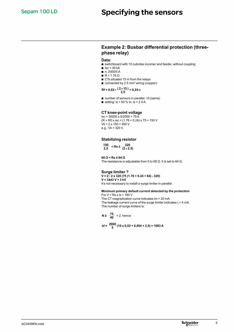
Example 2: Busbar differential protection (three-phase relay)Data:
switchboardwith10cubiclesincomerandfeeder,withoutcouplingIsc=30kAn:2000/5AR=1.76ΩCTssituated15mfromtherelaysconnectedby2.5mm2wiring(copper):
numberofsensorsinparallel:10(same)setting:is=50%In,is=2.5A.
CT knee-point voltageisc=30000x5/2000=75A(R+Rf)xisc=(1.76+0.24)x75=150VVk>2x150=300Ve.g.:Vk=320V.
Stabilizing resistor
60 Ω < Rs ≤ 64 ΩTheresistanceisadjustablefrom0to68Ω.Itissetto64Ω.
Surge limiter ?V = 2√ 2 x 320 (75 (1.76 + 0.24 + 64) - 320)V = 3443 V > 3 kVIt’snotnecessarytoinstallasurgelimiterinparallel.
Minimum primary default current detected by the protectionForV=Rsxis=160VTheCTmagnetizationcurveindicatesim=20mA.Theleakagecurrentcurveofthesurgelimiterindicatesil=4mA.Thenumberofsurgelimitersis:
bbbbbb
bb
1502,5 < Rs ≤ 320
(2 x 2,5)
Rf = 0,02 x ( 2 x 15 )2,5
= 0,24 Ω
N ≥ 7540 =2,hence
Id = 20005 (10 x 0,02 + 0,004 + 2,5) = 1083 A
AC0458EN.indd 5
Page 6
Surge limiterSepam 100 LDSepam 100 LD
IfthecalculationshaveshownthatitisnecessarytoinstallasurgelimiterinparallelwiththerelayandRstoprotecttheCTs,itisdeterminedasfollows..
ChoiceStandard references
thesurgelimitersonofferconsistoflimiterblockswhichareindependentofeachother.Eachblockacceptsamaximumcurrentof40ARMSfor1s.Byinstallingtheblocksinparallel,itispossibletoobtaintheappropriatelimiterfortheapplication.
therearetwostandardreferences:asinglemodule,comprisingoneblockatriplemodule,comprisingthreeindependentblockswhicharealigned.
Calculation of the number of blocks per phaseAccordingtoi,max.RMSshort-circuitcurrentinthesecondarywindingofaCT,thenumberofblocksrequiredperphaseiscalculated:
forathree-phaserelay,Ntriplemodulesshouldbeorderedforasingle-phaserelay,Nblocks,madeupoftripleandsinglemodules.
Example 1 max.RMSshort-circuitcurrentintheprimarywindingofaCT
witharatioof1000:60kAcalculationofthenumberofblocksperphase:
modulestobeordered:2triplemodulesforathree-phaserelay2singlemodulesforasingle-phaserelay.
Example 2max.RMSshort-circuitcurrentintheprimarywindingofaCT
witharatioof400:50kAsingle-phaserelay.calculationofthenumberofblocksperphase:
modulestobeordered:1triplemodule+1singlemoduletohave4blocksinall.
Earth leakage currentAlimiterblockacceptsamax.steadystatevoltageof325VRMSandpresentsanearthfaultcurrentlb:
b
bvv
bb
b
b
bvv
b
bb
b
DE
4094
6D
E40
946
N ≥ l40
N ≥ 60000(1000 x 40) = 1,5 ,henceN = 2
N ≥ 50000(400 x 40) = 3,1 , hence N = 4
AC0458EN.indd6
Page 7
Description and connectionSepam 100 LDSepam 100 LD
Rear panel Functional and connection diagram
DE
4094
5
DE
4094
4
0A : 8-pin CCA608 connector(torold and remote reloading inputs); screw terminal wiring with 0.6 to 2.5 mm2 wires, each terminal being capable of receiving two 1.5 mm2 wires.
Note: only 0A1 and 0A2 terminals are available in the single-phase version.
Terminal identificationEach terminal is identified by 3 characters.
DE
4094
3
1A : 8-pin CCA608 connector(power supply and “annunciation and tripping” outputs); screw terminal wiring with 0.6 to 2.5 mm2 wires, each terminal being capable of receiving two 1.5 mm2 wires.
1B : CCA604 connector ("annuciation" outputs);screw terminal wiring with 0.6 to 2.5 mm2 wires, each terminal being capable of receiving two 1.5 mm2 wires. t :groundterminal
1 A 4
Boardslotnumber(0to1)
Connectorterminalnumber
Connectoridentificationletter(AorB)
1 A 4
Boardslotnumber(0to1)
Connectorterminalnumber
Connectoridentificationletter(AorB)
AC0458EN.indd 7
Page 8
Stabilization plateConnectionofCTsandsurgelimiters:
5Arating:betweenterminals1-2and3-41Arating:betweenterminals1-2and5-6
DE
1041
8
items1to6:clampscrewconnectionsfor6mm2wireitems1,2:secondaryofCSH30corebalanceCT,connectedto0A
Wiretobeused:sheathed,shieldedwiremin.cross-section0.93mm2(AWG18)(max.2.5mm2)resistanceloadperunitlength<100mΩ/mmin.dielectricstrength:1000Vmax.length:2m.
Connectthewireshieldingintheshortestwaypossibleto0ATheshieldingisgroundedinSepam100LD.Donotgroundthewirebyanyothermeans.Pressthewireagainstthemetalframeofthecubicletoimproveimmunitytoradiatedinterference.
Surge limitersingleunit=outputswithscrewM10tripleunit=outputswithholesø10.4
(see,”installation”).
Example 1(N=2blocksperphase):2triplemodulesforathree-phaserelay.
bb
bb
bbbbb
bb
b
3212
3
Example 2(N=2blocksperphase):2singlemodulesforasingle-phaserelay.b Example 3(N=4blocksperphase)
1triplemodule+1singlemoduleforasingle-phaserelay.
b
DE
1040
8
DE
1040
9
3212
3
Example 2(N=2blocksperphase):2singlemodulesforasingle-phaserelay.b Example 3(N=4blocksperphase)
1triplemodule+1singlemoduleforasingle-phaserelay.
b
DE
1040
8
DE
1040
9
Connexion diagrams of the accessories
Sepam 100 LDSepam 100 LD
AC0458EN.indd8
Page 9
Example of applicationsSepam 100 LDSepam 100 LD
Restricted earth protection (single-phase)1A CT
DE
4094
2
Busbar protection (three-phase)5 A CT - with surge limiters
DE
4094
1
Note: = correspondence between primary and secondary connections (e.g. P1, S1).
AC0458EN.indd 9
Page 10
CharacteristicsSepam 100 LDSepam 100 LD
Electrical characteristicsAnalog inputs ( with plate)
Constantcurrent 10ln3sec.current 500lnLogic input ( remote reset)
Voltage 24/250Vdc 127/240VacMaximumpowerconsumption 3.5W 3.7VALogic outputs
Constantcurrent 8AVoltage 24/30Vdc 48Vdc 127Vdc/Vac 220Vdc/VacBreakingcapacity(contact01) Resistivedcload 7A 4A 0.7A 0.3A
Resistivedcload 8A 8AResistivedcload 3.4A 2A 0.3A 0.15AResistivedcload 4A 4A
Power supplyRange Consumption when inactive Max. consumption Inrush current
24/30Vdc ±20% 2.5W 6W <10Afor10ms48/125Vdc ±20% 3W 6W <10Afor10ms220/250Vdc -20%+10% 4W 8W <10Afor10ms100/127Vac -20%+10% 6VA 10VA <15Afor10ms220/240Vac -20%+10% 12VA 16VA <15Afor10msOperatingfrequency 47.5to63Hz
Environmental characteristicsClimatic
Operation IEC60068-2 -5°Cto55°CStorage IEC60068-2 -25°Cto70°CDampheat IEC60068-2 95%to40°CInfluence of corrosion IEC60654-4 ClassIMechanical
Degreeofprotection IEC60529 IP41 OnfrontVibration IEC60255-21-1 ClassIShocksandbumps IEC60255-21-2 ClassIEarthquakes IEC60255-21-3 ClassIFire IEC60695-2-1 GlowwireElectrical insulation
Powerfrequency IEC60255-5 2kV-1mn1.2/50µsimpulsewave IEC60255-5 5kVElectromagnetic compatibility
Immunitytoradiation IEC60255-22-3 ClassX 30V/mElectrostaticsicharges IEC60255-22-2 ClassIIISingle-directiontransients IEC61000-4-5Damped1MHzwave IEC60255-22-1 ClassIII5nsfasttransients IEC60255-22-4 ClassIVNote: “e” marking on our product guarantees their conformity to European directives.
AC0458EN.indd10
Page 11
InstallationSepam 100 LDSepam 100 LD
Sepam 100 LDRelay Cutout
DE
4094
0
Weight:1.9kg
Stabilization plate
DE
4093
9
Weight:1.7kg
AC0458EN.indd 11
Page 12
InstallationSepam 100 LDSepam 100 LD
Surge limiterSingle unit
DE
4093
8
Weight:1.2kgmax.
Triple unit
DE
4093
7
Weight:3.1kgmax.
AC0458EN.indd12
Page 13
Platebeforeinstallingtheplate,settherequiredresistanceusingtheohmmeterwirethecurrenttransformerstotheterminalsthatcorrespondtotheircurrent
rating,inparallelwithsurgelimiters:between1-2and3-4for5Abetween1-2and5-6for1A.
RelaysetmicroswitchSW1,locatedontheback,to“with”or“without”latching(seepage
3)adjustthefrontdialtotherequiredsetting.
bb
vv
b
b
DE
4093
6 TestingUsingatemporaryconnection(1turn),injectacurrent20%abovethesetting(5Arating)intothetoroidprimaryandcheckthattherelaytrips.
Example:Is=40%In.I=0.4x5Ax1.2=2.4A.
Thetestiscarriedoutoneachofthethreeplatesifathree-phaserelayisbeingused.
CommissioningSepam 100 LDSepam 100 LD
AC0458EN.indd 13
Page 14
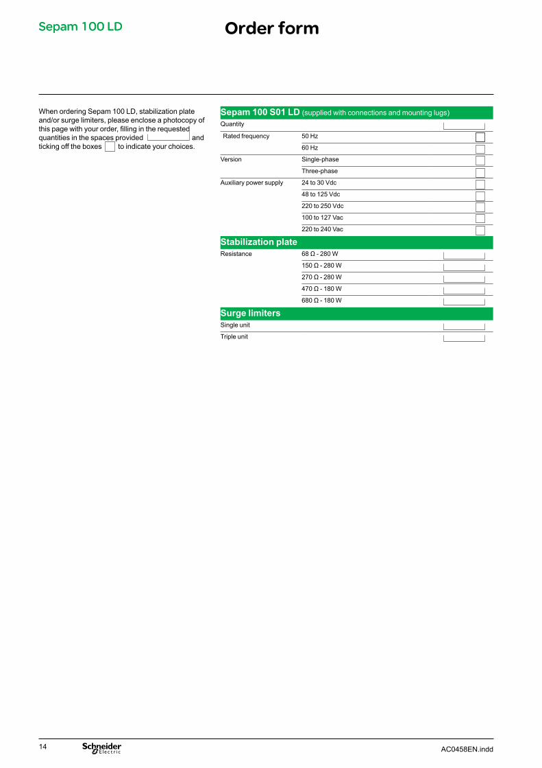
WhenorderingSepam100LD,stabilizationplateand/orsurgelimiters,pleaseencloseaphotocopyofthis page with your order, filling in the requested quantitiesinthespacesprovidedandtickingofftheboxestoindicateyourchoices.
Sepam 100 S01 LD (suppliedwithconnectionsandmountinglugs)Quantity
Ratedfrequency 50Hz
60Hz
Version Single-phase
Three-phase
Auxiliarypowersupply 24to30Vdc
48to125Vdc
220to250Vdc
100to127Vac
220to240Vac
Stabilization plateResistance 68 Ω - 280 W
150 Ω - 280 W
270 Ω - 280 W
470 Ω - 180 W
680 Ω - 180 W
Surge limitersSingleunit
Tripleunit
Order formSepam 100 LDSepam 100 LD
AC0458EN.indd14
Page 15
NotesSepam 100 LDSepam 100 LD
AC0458EN.indd 15
Page 16
NotesSepam 100 LDSepam 100 LD
AC0458EN.indd16