29

Ethernet Group Membership Protocol (EGMP)Draft RFC
David R. Cheriton
Stanford University and Granite Systems
Stephen E. Deering
Xerox PARC
Kenneth J. Duda
Granite Systems
October 22, 1995
1 Status of This Memo
This memo is a draft speci�cation of EGMP, a MAC- or datalink-level protocol for explicitly joiningand leaving groups corresponding to multicast and unicast addresses on an extended LAN suchas switched/bridged Ethernet and other network technologies using Ethernet addresses, such asFDDI. It provides a MAC-level analog to IGMP [6]. That is, EGMP allows the extended LANto deliver packets addressed to a multicast address to only those LAN segments with endstationsthat have explicitly joined the group corresponding to that multicast address. Ancillary to themulticast membership, EGMP supports determining the location of endstations corresponding tospeci�c unicast addresses. Distribution of this memo will be unlimited. Currently its distributionis restricted until reviewed and revised further.
2 Introduction
Multicast on broadcast networks such as conventional Ethernets is implemented by delivering thepacket to each endstation interface and �ltering by address at each interface. That is, the networkis expected to broadcast the multicast packets and each endstation interface only allows through themulticast packets whose destination addresses match those of the endstation interface multicast �lter.Packets to all other addresses are discarded1. (This is the normal mode of operation. An endstationinterface can also be set to receive all multicast packets, or even all packets, so-called promiscuousmode.) In this basic model, there is no indication to the network whether an endstation is interestedin a given multicast packet or not.
In extended LANs consisting of individual LAN segments interconnected by bridges, each bridgeforwards a multicast packet on all ports on the spanning tree other than the incoming port. This ooding behavior is required to provide the underlying broadcast distribution described above forthe single-segment LAN. This broadcast distribution does not scale well because it loads the wholeextended LAN with the sum of the multicast (and broadcast) tra�c of all sources on the extendedLAN.
1In practice, this �ltering is imperfect. The typical interface uses a 64-bucket hash which lets through packets that
hash to any enabled bucket. With birthday problem collisions, there can be a signi�cant number of unwanted packets
coming through the �lter.
1
The introduction of sophisticated Ethernet switches provides the potential for signi�cant scalingof Ethernets. The standard Ethernet interface becomes purely an access protocol. The conventionalbroadcast implementation is replaced with a switched fabric with higher aggregate bandwidth thanthat of individual links. However, a key de�ciency with the standard Ethernet access protocol is a lackof an indication of the multicast addresses that an endstation wants to receive. The current move tohigher-speed Ethernet and the growing use of multicast for video delivery and other high-bandwidthapplications further motivates addressing this problem at the present time.
The Ethernet Group Membership Protocol (EGMP) addresses this de�ciency. It is a datalink-layer protocol that allows a switch (or bridge) to determine the endstation interfaces that are inter-ested in receiving a particular Ethernet address, both multicast and unicast. EGMP also supportsindicating an interest in receiving unicast addresses to allow learning switches and bridges to locateindividual endstations. Using this facility in EGMP, a switch can avoid broadcasting packets ad-dressed to unicast addresses that it has not previously located. It also provides a means for a switchto detect whether an endstation with a particular unicast address supports EGMP.
EGMP is also used as an inter-switch protocol to communicate membership in groups corres-ponding to multicast and unicast addresses between switches in a multi-switch con�guration. Inessence, a switch acts as a proxy for its connected endstations, joining the groups corresponding tothe multicast addresses that its endstations belong to, but e�ectively joining these groups in otherswitches. EGMP relies on the standard spanning tree algorithm to avoid packet loops and duplicatesin multi-switch con�gurations. Use of EGMP with other routing protocols is a subject for futurestudy.
EGMP is based in part on the Host Membership Protocol described by Deering [7] (and stand-ardized as IGMP [6]), but operates at the Ethernet level, not the IP level. EGMP provides LANsegment membership within an extended LAN whereas IGMP e�ectively creates a single member-ship for entire extended LANs at the routers for each multicast address with local members. EGMPin conjunction with IGMP provides e�cient delivery of multicast to hosts interested in particularIP multicast addresses. EGMP can also be used with other network-layer protocols such as IPX,Appletalk and XNS.
In contrast to IGMP version 1, EGMP de�nes an explicit leave protocol mechanism to reduce\leave latency", as recently added to IGMP version 2 [5]. Leave latency refers to the time betweenwhen an endstation decides it is no longer interested in being a member of a group (i.e. receivingpackets for that group's address) and the packets are no longer being forwarded to this endstation'sLAN or LAN segment, assuming this endstation is the last one that was interested in packets to thisaddress on this LAN segment. Low leave latency is important to keep up with this multicast addressswitching rate and to avoid having memberships persist to old addresses, thereby wasting excessiveamounts of bandwidth. For example, a video application that changes memberships rapidly couldoverwhelm its LAN segment with reception of packets sent to its old memberships that have not beenturned o� by the switch because of the long leave latency. With the growing use of multicast for high-bandwidth services such as video and distributed virtual reality, and the splitting of the aggregateapplication bandwidth over multiple multicast addresses, multicast receivers can be expected toswitch memberships across multiple multicast addresses fairly quickly. These uses of multicast areexpected to become more prevalent in the future making low leave latency of increasing importance.(Note that low EGMP leave latency is of considerable bene�t for individual LAN segments even ifIGMP leave latency is higher because terminating an EGMP membership still stops the tra�c fromentering the LAN segment. The switch, which is still receiving the multicast tra�c because of IGMP,
2
has a much higher internal bandwidth and is capable of handling a larger number of multicast groupsthan individual ports and links.
Monitoring IGMP tra�cwithin a switch, a (rejected) alternative to EGMP, has been implementedby at least one vendor. However, this approach does not work in all topologies and can cause holesin the multicast delivery. It also represents a signi�cant layer violation that seems inappropriate toperpetrate.
As a multicast mechanism, EGMP functionality is not provided by InARP [2] or ATMARP [10]as currently speci�ed. The latter leaves open the handling of multicast, and might bene�t from theuse of EGMP or some extension of EGMP. ATMARP does incorporate the notion of an ARP server,similar in some respects to the role of the interrogator in EGMP. In general, there are some parallelsin the structure of the protocols but currently no overlap in functionality.
The authors just recently became aware of the IEEE 802.1 e�ort to address some of these issues [9].It is hoped that some merger of these e�orts is feasible, rather than two protocols for the same service.
2.1 Transition Plan
Fully deploying EGMP means inverting the conventional multicast delivery from \broadcast on allLAN segments" to \send only if requested". To phase in EGMP, each switch or bridge should allowits ports to operate in one of two modes correspondingly to broadcast mode and EGMP mode, asdescribed in Section 7. In broadcast mode, all multicast packets are forwarded to that port/LANsegment, allowing non-EGMP endstations to receive multicast correctly. When only EGMP devicesare connected to a port, the port is placed in EGMP mode so that multicast packets addressed toa given address are only forwarded if they have been requested by joining their respective groups.Switch/bridge vendors can by default ship product with all ports in the broadcastmode so they \plug-and-play" with existing equipment. Customers are motivated to upgrade endstations to supportEGMP and to change the ports to EGMP mode as the multicast tra�c level increases and theconventional broadcast mode overwhelms LAN segments with unwanted multicast tra�c. Systemvendors are motivated to incorporate EGMP if it is a standard to allow their systems to work wellwith high-performance switches in demanding applications, such as video conferencing.
2.2 Why Use ONC RPC and GMP?
EGMP is de�ned in terms of a general-purpose Group Membership Protocol (GMP) de�ned as aremote procedure call interface, in contrast to conventional MAC and network layer protocols in usein the Internet. The packet formats and basic handling are de�ned by ONC RPC [17] and XDR [16],treating the GMP procedures as remote procedure calls.
EGMP uses GMP and ONC RPC so as to build on existing technology, to avoid contributing tothe growing protocol chaos in the Internet, and to provide the generality that is needed for the futureextensions. The basic ONC RPC procedures are described in the appendix.
Considering existing RPC technology, EGMP could be generated using RPC stub generators inthe future (although it is not required for an implementation). Also, the RPC transport and au-thentication mechanisms could be used without changing the basic procedure-speci�ed protocol. Forexample, EGMP could be extended with backwards compatibility to provide authenticated member-ships using the standard ONC RPC security mechanisms. In this case, a client implementation notsupporting authentication would simply report an authentication error to the higher-level softwarewhen it attempted to use a membership service requiring authentication.
3

Considering the protocol chaos issue, basing EGMP on GMP provides the potential of using thesame basic RPC interface at a number of levels, from datalink level to application-level services.This unity is attractive because a person developing or maintaining a multicast-based service maybe forced to understand and perhaps debug multicast protocols and management mechanisms at allthe levels. After all, it does have to work at all levels for the application to work.
ONC RPC was chosen because it is the most widely used RPC system and it is relatively simpleto describe in packet formats. Although ONC RPC is normally transported over UDP, it can alsofunction using Ethernet packets directly, at least for low-level services such as EGMP that existat the datalink level. Using RPC at the datalink level is regarded as a \recursive" design [4] inwhich higher-level protocols are implemented in terms of restricted versions of themselves, ratherthan as separate ad hoc protocols, as has been the practice to date. As with recursion in general,this recursive structure to the protocols leads to a simpler, more regular design.
As a concession to current Internet practice, EGMP is described at the packet level so it can beimplemented directly without knowledge of ONC RPC or XDR and without the use of RPC stubgenerator tools.
Finally, the cost of using an RPC framework is relatively low. EGMP requires 2 extra packetformats over the single packet format that would be feasible if the design followed the conventionalapproach as taken by the IGMP Version 1. The use of ONC RPC also adds about 28 bytes to thepacket size over an IGMP-like packet design. However, we conjecture that the ability to providea list of addresses in a single membership packet reduces the number of EGMP packets and thetotal amount of data sent compared to IGMP version 1 in most network con�gurations. Moreover,the packet and bandwidth requirements for EGMP is expected to be very low. Finally, the actualnumber of packets sent is basically the same as a message-based IGMP-like protocol.
The rest of this document describes the RPC basis for EGMP using a generic group membershipprotocol, the EGMP protocol itself, how it is to be used with IP routers and similar devices, inter-switch operation with EGMP and some suggestions for implementations.
3 GMP: RPC Group Membership Protocol
Group Membership Protocol (GMP) is a general-purpose membership protocol de�ned as an RPC-implemented interface. We �rst describe the protocol model and then the speci�c procedures.
3.1 GMP Model
The basic GMP model is that of a membership service provided by one or more servers, allowingclients to join and leave groups. A client requests one or more memberships from the membershipserver, specifying the groups that it wishes to join. The server can accept or reject the membershiprequest. A client can also request the termination of one or more memberships.
Periodically, the server can propose to terminate one or more or all memberships held by a clientor a subset of clients (multicasting the call to that subset in the latter case). The subset of memberclients typically corresponds to those connected by some common communication mechanism, suchas those connected to one port of the switch in the case of EGMP. In response to the server, theclients re-request the memberships to get the memberships extended, if the server is willing and ableto do so. By periodically forcing the clients to rejoin, the server gets the clients to rea�rm theirinterest in the memberships, e�ectively garbage-collecting memberships that are no longer of interest.
4

3.2 GMP Procedures
GMP contains the following procedures in its interface.
void join( MembershipDesc desc )
void leave( MembershipDesc desc )
Both procedures are implemented and exported by a membership server and called by the client.Each EGMP server also implements client EGMP to resend client calls and for inter-switch operation,as described in Section 6.
The semantics of these procedures are as follows:
void join( MembershipDesc desc ) - Ensure there are memberships for the address(es) describedby desc. That is, create the memberships if they do not exist or extend existing memberships.
void leave( MembershipDesc desc ) - Remove the memberships described by desc unless an-other join call is received that requests these memberships for the same client or subset ofclients. In the case of EGMP, the subset of clients normally corresponds to those attached toone or more ports of the switch. This is a datagram call.
The format and semantics of the membership descriptions is speci�c to particular protocols. Theformat for EGMP descriptions is covered in the next section. The EGMP membership server isnormally implemented as part of the Ethernet switch. Other protocols based on GMP can use theirown membership servers, with their own membership description formats and separate multicastaddresses.
3.3 Role of the RPC System
These procedures are mapped to packets by a remote procedure call system. EGMP uses the ONCRPC and XDR standards to map to packets, except the packet is an Ethernet packet rather than aUDP or TCP packet. Other RPC systems can use the same GMP speci�cation for other membershipuses, such as for application server memberships services. The RPC system is also expected toprovide authentication and other security services if that is required in the application domain.
4 EGMP Protocol Description
The basic service of EGMP is the protocol to join a group associated with a multicast or unicastaddress in order to receive packets sent to this address. EGMP also supports source �ltering, allowingan endstation to ask a switch or bridge to restrict the packets the endstation receives addressed toa speci�c multicast address to those sent by a speci�ed set of the sources. The joining station canspecify the set either by specifying the included sources or the excluded sources. (A similar facilityhas been proposed for IGMP version 3 [3].)
EGMP uses the Ether type �eld value allocated for Ethernet-level ONCRPC (yet to be allocated).In its use as an endstation-to-switch protocol, all EGMP call packets are transmitted to a single
well-known (yet to be allocated) Ethernet multicast address referred to as the EGMP address. Callresponses (when used) are unicast to the caller. In its use as a switch-to-switch protocol, EGMP callpackets are multicast using a separate EGMP inter-switch multicast address (yet to be allocated).
5
Normally, an Ethernet switch acts as the membership server for EGMP. The switch does notforward (EGMP) packets addressed to this one address to other LAN segments, so endstations onother LAN segments do not receive EGMP tra�c not local to their segment. (This di�ers fromthe IGMP approach of sending each Report to the multicast address of the group for which it isreporting. Although the EGMP approach means that all endstations on the LAN segment receiveevery EGMP packet, the level of tra�c is not expected to be signi�cant.)
4.1 Membership Descriptor
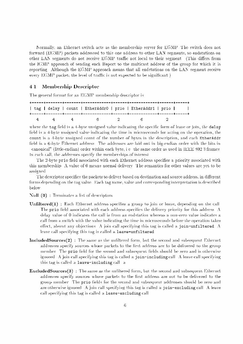
The general format for an EGMP membership descriptor is
+-----+-------+-------+------------+------+------------+------+-----+
| tag | delay | count | EtherAddr0 | prio | EtherAddr1 | prio | ... |
+-----+-------+-------+------------+------+------------+------+-----+
4 4 4 6 2 6 2
where the tag �eld is a 4-byte unsigned value indicating the speci�c form of leave or join, the delay�eld is a 4-byte unsigned value indicating the time in microseconds for acting on the operation, thecount is a 4-byte unsigned count of the number of bytes in the description, and each EtherAddr
�eld is a 6-byte Ethernet address. The addresses are laid out in big-endian order with the bits in\canonical" (little-endian) order within each byte, i.e. the same order as used in IEEE 802.3 frames.In each call, the addresses specify the memberships of interest.
The 2-byte prio �eld associated with each Ethernet address speci�es a priority associated withthis membership. A value of 0 means normal delivery. The semantics for other values are yet to beassigned.
The descriptor speci�es the packets to deliver based on destination and source address, in di�erentforms depending on the tag value. Each tag name, value and corresponding interpretation is describedbelow.
Null (0) : Terminates a list of descriptors.
Un�ltered(1) : Each Ethernet address speci�es a group to join or leave, depending on the call.The prio �eld associated with each address speci�es the delivery priority for this address. Adelay value of 0 indicates the call is from an endstation whereas a non-zero value indicates acall from a switch with the value indicating the time in microseconds before the operation takese�ect, absent any objections. A join call specifying this tag is called a join-unfiltered. Aleave call specifying this tag is called a leave-unfiltered.
IncludedSources(2) : The same as the un�ltered form, but the second and subsequent Ethernetaddresses specify sources whose packets to the �rst address are to be delivered to the groupmember. The prio �eld for the second and subsequent �elds should be zero and is otherwiseignored. A join call specifying this tag is called a join-including call. A leave call specifyingthis tag is called a leave-including call. a
ExcludedSources(3) : The same as the un�ltered form, but the second and subsequent Ethernetaddresses specify sources whose packets to the �rst address are not to be delivered to thegroup member. The prio �elds for the second and subsequent addresses should be zero andare otherwise ignored. A join call specifying this tag is called a join-excluding call. A leavecall specifying this tag is called a leave-excluding call.
6
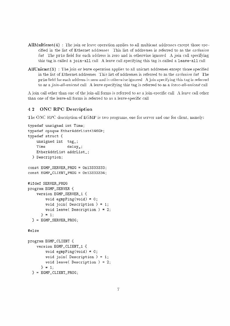
AllMulticast(4) : The join or leave operation applies to all multicast addresses except those spe-ci�ed in the list of Ethernet addresses. This list of addresses is referred to as the exclusionlist. The prio �eld for each address is zero and is otherwise ignored. A join call specifyingthis tag is called a join-all call. A leave call specifying this tag is called a leave-all call.
AllUnicast(5) : The join or leave operation applies to all unicast addresses except those speci�edin the list of Ethernet addresses. This list of addresses is referred to as the exclusion list. Theprio �eld for each address is zero and is otherwise ignored. A join specifying this tag is referredto as a join-all-unicast call. A leave specifying this tag is referred to as a leave-all-unicast call.
A join call other than one of the join-all forms is referred to as a join-speci�c call. A leave call otherthan one of the leave-all forms is referred to as a leave-speci�c call.
4.2 ONC RPC Description
The ONC RPC description of EGMP is two programs, one for server and one for client, namely:
typedef unsigned int Time;
typedef opaque EtherAddrList<1460>;
typedef struct {
unsigned int tag_;
Time delay_;
EtherAddrList addrList_;
} Description;
const EGMP_SERVER_PROG = 0x13333333;
const EGMP_CLIENT_PROG = 0x13333334;
#ifdef SERVER_PROG
program EGMP_SERVER {
version EGMP_SERVER_1 {
void egmpPing(void) = 0;
void join( Description ) = 1;
void leave( Description ) = 2;
} = 1;
} = EGMP_SERVER_PROG;
#else
program EGMP_CLIENT {
version EGMP_CLIENT_1 {
void egmpPing(void) = 0;
void join( Description ) = 1;
void leave( Description ) = 2;
} = 1;
} = EGMP_CLIENT_PROG;
7
#endif
Following ONC RPC conventions, procedure 0 in both server and client is a null \ping" procedure.\Compiling" this description through the standard rpcgen program produces RPC stubs that
generate and handle the EGMP packet formats, which are described directly below for version 2ONC RPC.
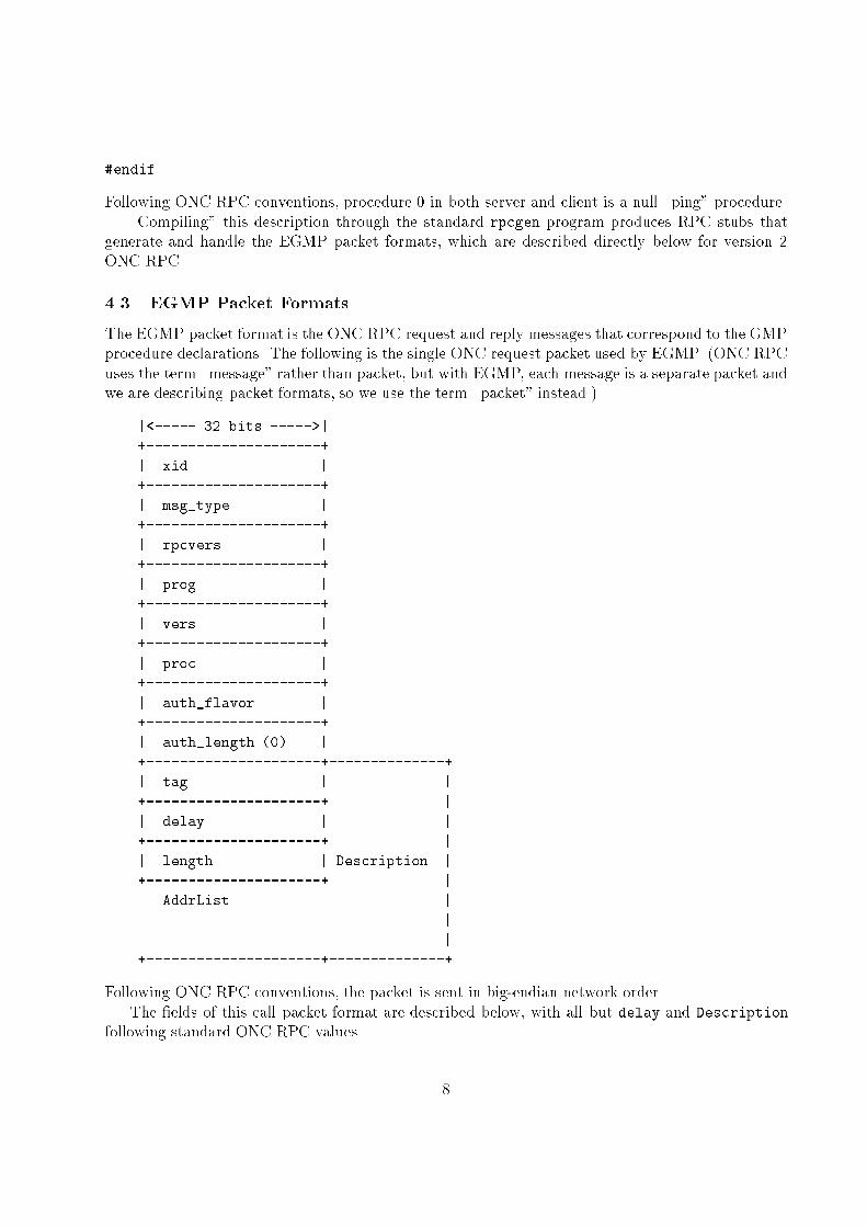
4.3 EGMP Packet Formats
The EGMP packet format is the ONC RPC request and reply messages that correspond to the GMPprocedure declarations. The following is the single ONC request packet used by EGMP. (ONC RPCuses the term \message" rather than packet, but with EGMP, each message is a separate packet andwe are describing packet formats, so we use the term \packet" instead.)
|<----- 32 bits ----->|
+---------------------+
| xid |
+---------------------+
| msg_type |
+---------------------+
| rpcvers |
+---------------------+
| prog |
+---------------------+
| vers |
+---------------------+
| proc |
+---------------------+
| auth_flavor |
+---------------------+
| auth_length (0) |
+---------------------+--------------+
| tag | |
+---------------------+ |
| delay | |
+---------------------+ |
| length | Description |
+---------------------+ |
. AddrList . |
. . |
. . |
+---------------------+--------------+
Following ONC RPC conventions, the packet is sent in big-endian network order.The �elds of this call packet format are described below, with all but delay and Description
following standard ONC RPC values.
8

xid - the transaction identi�er, incremented on each EGMP call from each source, starting from 1.
msg type - 0 for call.
rpcvers - 2, current version of ONC RPC.
prog - 0x1f333333 for client, 0x1f333334 for server (to be assigned for GMP)
vers - 1, �rst version of EGMP.
proc - corresponding to the 3 procedures of (E)GMP.
� ping - 0
� join - 1
� leave - 2
auth avor - the value of 0 for standard AUTH NULL.
auth length - 0, because of the null authentication.
tag - The tag �eld is a 32-bit unsigned integer specifying the interpretation of the rest of the �elds,as described in Section 4.1
delay - The delay �eld is a 32-bit unsigned integer specifying the maximum delay in microseconds.
The microsecond granularity is chosen (rather than milliseconds) to allow for fast leave frommulticast groups. For example, it is feasible to request leaving a group within a 500microsecondinterval over 100Mb Ethernet using fast machines, and it may be feasible to use even tighterbounds on 1 Gigabit (full-duplex) Ethernet in the future.
length - the length �eld of an XDR variable-length opaque data type, specifying the number of bytesto follow. It is assumed to be a multiple of 8 bytes, ranging from 0 to the number of 8-byteunits that �ts in a single Ethernet packet, i.e., (1500� 40)=8 = 182 addresses. If the count isnot a multiple of 8, the value is interpreted as rounded down to the next lowest multiple of 8.
etherAddrList - Zero or more Ethernet addresses left-aligned on 8-byte boundaries, padded witha 16-bit priority �eld in the low-order portion, the number being that which will �t into 8-byteunits.
A call can carry multiple membership descriptors, with the last one being terminated by a nulldescriptor. However, the call message must still �t into a single Ethernet packet. (An extensionto the RPC description is required to provide multiple membership descriptors per call.
The following is the EGMP return packet format for an accepted call.
|<----- 32 bits ----->|
+---------------------+
| xid |
+---------------------+
| msg_type |
+---------------------+
9

| reply_stat |
+---------------------+
| auth_flavor |
+---------------------+
| auth_length (0) |
+---------------------+
| accept_stat |
+---------------------+
| low |
+---------------------+
| high |
+---------------------+
The �elds of this return packet format are described below,
xid - the transaction identi�er, matching the call xid to which this is a return message.
msg type - 1 for REPLY.
reply stat - 0 for MSG ACCEPTED (and otherwise it is a rejected message | see below.)
auth avor - the value of 0 for standard AUTH NULL.
auth length - 0, because of the null authentication.
accept stat - the standardONCRPC values, namely SUCCESS (0), PROG UNAVAIL(1),PROG MISMATCH
(2), PROC UNAVAIL (3) and GARBAGE ARGS(4).
low,high - are only used with PROG MISMATCH (2) to indicate the low and high versions of theprogram that are supported by the server, as with standard ONC RPC.
The following is the EGMP return packet format for a rejected call.
|<----- 32 bits ----->|
+---------------------+
| xid |
+---------------------+
| msg_type |
+---------------------+
| reply_stat |
+---------------------+
| reject_stat |
+---------------------+
| low |
+---------------------+
| high |
+---------------------+
The �elds of this return packet format for rejected call are described below,
10
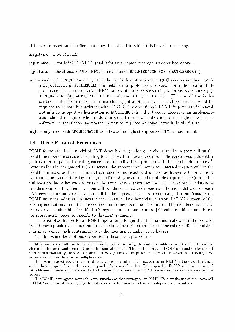
xid - the transaction identi�er, matching the call xid to which this is a return message.
msg type - 1 for REPLY.
reply stat - 1 for MSG DENIED. (and 0 for an accepted message, as described above.)
reject stat - the standard ONC RPC values, namely RPC MISMATCH (0) or AUTH ERROR (1).
low - used with RPC MISMATCH (0) to indicate the lowest supported RPC version number. Witha reject stat of AUTH ERROR, this �eld is interpreted as the reason for authentication fail-ure, using the standard ONC RPC values of AUTH BADCRED (1), AUTH REJECTEDCRED (2),AUTH BADVERF (3), AUTH REJECTEDVERF (4), and AUTH TOOWEAK (5). (The use of low is de-scribed in this form rather than introducing yet another return packet format, as would berequired to be totally consistent with ONC RPC conventions.) EGMP implementations neednot initially support authentication so AUTH ERROR should not occur. However, an implement-ation should recognize when it does arise and return an indication to the higher-level clientsoftware. Authenticated memberships may be required on some networks in the future.
high - only used with RPC MISMATCH to indicate the highest supported RPC version number.
4.4 Basic Protocol Procedures
EGMP follows the basic model of GMP described in Section 3. A client invokes a join call on theEGMP membership service by sending to the EGMP multicast address2. The server responds with a(unicast) return packet indicating success or else indicating a problem with the membership request3.Periodically, the designated EGMP server, the interrogator4, sends an leave datagram call to theEGMP multicast address. This call can specify multicast and unicast addresses with or withoutexclusions and source �ltering, using one of the 5 types of membership descriptors. The join call ismulticast so that other endstations on the same LAN segment see the call. These other endstationscan then skip sending their own join call for the speci�ed addresses so only one endstation on eachLAN segment actually sends a join call in the expected case. A leave call, also multicast to theEGMP multicast address, noti�es the server(s) and the other endstations on the LAN segment of thesending endstation's intent to drop one or more memberships or sources. The membership servicedrops these memberships for this LAN segment unless one or more join calls for this same addressare subsequently received speci�c to this LAN segment.
If the list of addresses for an EGMP operation is longer than the maximum allowed in the protocol(which corresponds to the maximum that �ts in a single Ethernet packet), the caller performsmultiplecalls in sequence, each containing up to the maximum number of addresses.
The following descriptions elaborate on these basic procedures.
2Multicasting the call can be viewed as an alternative to using the multicast address to determine the unicast
address of the server and then sending to that unicast address. The low frequency of EGMP calls and the bene�ts of
other clients monitoring these calls makes multicasting the call the preferred approach. However, multicasting these
requests also allows there to be multiple servers.3The return packet obviates the need for a client to send multiple packets as in IGMP in the case of a single
server. In the expected case, the server responds after one call packet. The responding EGMP server can also send
out additional membership calls on the LAN segment to ensure other EGMP servers on this segment received the
request.4The EGMP interrogator serves the same function as the interrogator in IGMP. We view the use of the leave call
in EGMP as a form of interrogating the endstations to determine which memberships are still of interest.
11

4.4.1 The join Call
The EGMP join call is transmitted by a node on its LAN segment, addressed to the EGMP Ethernetmulticast address.
The delay �eld shall be set to 0 meaning an inde�nite membership period, namely until an explicit(unchallenged) leave by this member or the next leave-all is invoked by the interrogator or one of theother servers.
The EtherAddrList �eld contains zero or more valid Ethernet addresses.The interpretation of the call parameters varies depending on the tag �eld:
Un�ltered(1) : Join each group speci�ed by an address in the Ethernet address list. The prio
�eld associated with each address speci�es the delivery priority for this address.
IncludedSources(2) : The same as the un�ltered form but request delivery only for packets sentto the �rst address that are sent from a source speci�ed as one of the second and subsequentEthernet addresses, if any. The prio �elds for the second and subsequent addresse should bezero and are otherwise ignored.
ExcludedSources(3) : The same as the un�ltered form but request delivery only for packets sentto the �rst address that are sent from a source other than those speci�ed by the second andsubsequent Ethernet addresses. The prio �elds for the second and subsequent addresses shouldbe zero and are otherwise ignored.
AllMulticast(4) : Join all multicast addresses except those speci�ed in the list of Ethernet ad-dresses. The prio �eld for each such address is zero and is otherwise ignored.
AllUnicast(5) : Join all unicast addresses except for those speci�ed in the list of Ethernet ad-dresses. The prio �eld for each such address is zero and is otherwise ignored.
Unicast membership as supported in the protocol arises in three situations. A node invokes thisjoin call: (1) in response to a leave call containing its unicast address or in response to a leave-all-unicast call. and (2) when the node boots (at the point its network interface is ready to receivepackets), and (3) to sni� tra�c to the speci�ed unicast address. Note that a node does not includeits own unicast address in join calls generated in response to a leave-all call.
A join-excluding call can specify a unicast address, typically the unicast address of the endstationrequesting the exclusion, followed by one or more unicast addresses for sources to exclude. This callcauses the switch to �lter out unicast tra�c coming from the speci�ed excluded sources when it wassent to this speci�c endstation.
The source �ltering aspect of a join-including or join-excluding call is a hint to the switch whichit can act on if convenient and supported. Otherwise, the packets from the excluded destinationsand sources continue to be forwarded. It is also \soft state" in the sense that the switch can dropthe information and simply recreate this state when \reminded" by the endstations. In this sense,switches need to deliver a superset of the packet tra�c speci�ed in EGMP; it is optional whether aswitch implements the strict subset of delivery that is speci�ed by the client.
A switch needs to join groups that it needs to forward. In the normal case, it invokes a join-all callon each LAN segment from which it forwards packets, specifying in the exclusion list of addressesthose that other endstations on the LAN segment have joined. (The latter exclusion means that theendstations continue to notify the switch of their interest, rather than having it overridden by an
12

(unrestricted) join-all call. With this switch behavior, there is an explicit (membership) request,possibly as a join-all, for every address thatis of interest to switches or endstations on the LANsegment. Therefore, an endstation can determine by monitoring the EGMP tra�c that there is nointerest in a particular multicast and prune tra�c to that address back to the endstation, so thesepackets are not even forwarded onto the LAN segment.
4.4.2 Switch join Call Handling
On receiving a join call, a switch notes the existence of one or more members on the LAN segmentfromwhich the join call was received, for each group speci�ed in the call. For each such membership,if the call also speci�es desired sources, the switch records these desired sources as well, as speci�edsources to receive from or as all but the set of speci�ed sources. It need not record the identity ofthe caller of the join call.
The switch then sends a unicast response message to the caller.The packets forwarded onto a given LAN segment are the union of all those requested by join
calls on this LAN segment. In particular, the set of allowed sources for a given address is the unionof all sources allowed by all the join calls for this address.
The switch may optionally reinvoke this same join call on the same LAN segment to ensurethat any other switch on this segment is aware of this membership. This retransmission guardsagainst single packet loss causing another switch to not know of this membership. The number ofretransmissions is an administrator controlled parameter.
4.4.3 Endstation join Call Handling
On receiving a join call, an endstation checks whether it has scheduled a join call for any of thegroup addresses listed in the received join call, typically in response to a leave call. If so and thesource �ltering in this call also subsumes that of the local membership, it unschedules the call(s) foreach such address.
Optionally, the endstation may support pruning back to the endstation, where it does not sendpackets destined for a particular multicast address because there are no receivers. In this case, theendstation shall check if it has pruned one or more of the addresses mentioned in the join call backto the endstation and, if so, resume forwarding packets to this address onto the LAN segment.
This completes the processing in the endstation. The endstation does not respond to the call.
4.4.4 The leave Call
An leave call requests canceling memberships to one or more groups on a LAN segment. It isinvoked when an endstation stops listening to a multicast group or when an endstation wants to stopreceiving from one or more sources of tra�c to a speci�ed multicast address or when an endstationvoluntarily disconnects from the network. In this latter case it leaves the group(s) corresponding toits unicast address(es), eliminating the address(es) as a valid destination for packets.
The call is viewed as \requesting" cancelation of a membership because other endstations on thesame LAN segment may still need to receive these packets and override the cancellation by joiningthe group in response to the leave call.
The leave-all call is also sent by the switches periodically to force the endstations to rejoin, therebyallowing it to garbage collect any memberships that are no longer of interest. The leave call reduces
13
the latency to terminate a membership compared to waiting this garbage collection mechanism tocancel the membership.
When a switch ceases to need to forward packets to a given multicast address from a LANsegment, it can send a leave-speci�c call for this address on this LAN segment. It then also adds thisaddress to the exclusion list that it sends with subsequent join-all requests on this LAN segment.
An endstation shall use 0 as the delay value to indicate the call came from an endstation. Whenthe leave call is invoked by a switch, the delay �eld logically speci�es the time in microseconds withinwhich a join call should be received to counter the reduced delivery of packets proposed by the leavecall. A switch invokes leave with a delay that is appropriate to allow endstations to respond withappropriate join calls.
The interpretation of the call parameters varies depending on the tag �eld:
Un�ltered(1) : Leave each group speci�ed by an address in the Ethernet address list. The prio�eld associated with each address should be zero and is otherwise ignored.
IncludedSources(2) : Request stopping the delivery of packets with destination address as the�rst address and source address one of the second or subsequent addresses in the address list.The prio �eld for each such addresses should be zero and is otherwise ignored.
ExcludedSources(3) : Request stopping the delivery of packets with destination address as the�rst address and source addresses other than the second or subsequent addresses in the addresslist. The prio �eld for all addresses should be zero and is otherwise ignored.
AllMulticast(4) : Request stopping reception of packets to all multicast addresses except thosespeci�ed in the list of Ethernet addresses. The prio �eld for each such address is zero and isotherwise ignored.
AllUnicast(5) : Request stopping reception of packets to all unicast addresses except those spe-ci�ed in the list of Ethernet addresses. The prio �eld for each such address is zero and isotherwise ignored.
As an optimization in the case of stopping reception of all packets for a particular multicastaddress, only the endstation that last issued a join call for the group on the LAN segment generatesa leave call when leaving the group5. If the leaving endstation was not the last one to issue a join callfor this group, there is at least one other endstation on this LAN segment interested in this group.This optimization assumes it is unlikely that the last member endstation crashed since the join call,and failed to generate the leave call. In the case of the join caller being the only other member andcrashing, the multicast packets for this address are forwarded to this LAN segment unnecessarilyuntil the next leave-all period. This situation is considered unlikely to arise and not a signi�cantproblem when it does.
4.4.5 Switch leave Call Handling
When an interrogator switch receives a leave call, it schedules a subsequent leave call for the addressesspeci�ed by this �rst call, to be sent after leaveDelay. The value of delay speci�ed in this subsequentcall is leaveDelay.
5This optimization, due to Rosen Sharma, is also used in IGMP Version 2.
14

If a join call is received between the time of this �rst call and leaveDelay microseconds laterthat requests delivery of packets that are not to be delivered according to the scheduled leave call,the scheduled leave call's descriptor is modi�ed so that is not the case. For example, if the leavecall speci�es ceasing delivery of packets to a destination m from sources s1 and s2 and the join callis a join-including call specifying destination m and s1, then s1 is removed from descriptor of thescheduled leave call.
After leaveDelay microseconds, if the descriptor in the scheduled call is null, the switch deletesthe scheduled call and terminates the handling of the leave call. Otherwise, the second leave call issent and the switch delays for another leaveDelay microseconds.
If a join call is received from that LAN segment whose descriptor con icts with that speci�edin the leave call, the membership for each such address is retained for that LAN segment. AfterleaveDelay microseconds plus some time to allow for packet queuing and processing at the interrog-ator, the uncontested reduction of the packet delivery is imposed, dropping memberships as well assource �ltering as speci�ed.
The number of retransmissions of the leave call before the membership is completely deletedshould be user-con�gurable in the switch.
The value of leaveDelay is recommended to be at least 10 times the maximum packet transmissiontime, e.g., 1.2 milliseconds for 100 Mb Ethernet and 12 milliseconds for 10 Mb Ethernet. The switchshould increase this value if the LAN segment is shared, under heavy tra�c, or the leave call speci�esa large number of addresses.
The leave call by the interrogator ensures that a single packet loss cannot result in the packet owfor the speci�ed address being stopped on this LAN segment. That is, another member endstationon the same LAN segment sees either the client's leave call packet or the interrogator's leave callunless multiple packet loss occurs. EGMP requires there be at least two leaves before shutdown.However, the switch can skip sending the separate leave call altogether and immediately terminatethe packet forwarding if it is certain that the LAN segment contains a single endstation such as whenit is explicitly con�gured with a single endstation on that segment.
A leave-all call removes the join-all membership in the switch for this LAN segment but it doesnot remove memberships in speci�c groups speci�ed in the address list. This allows a client or switchto change from a join-all with pruning approach to speci�c memberships without losing packets.
Switches other than those running the interrogator for a LAN segment perform the same actionsas the interrogator except they do not send the second leave call (in response to the endstation'sleave call). That is, a non-interrogator switch notes the leave call by the endstation and then, if thefollowing leave call by the interrogator is unanswered after leaveDelay microseconds, stops forwardingtra�c onto the LAN segment whose delivery is no longer required. If the interrogator fails to senda leave call, the switch can send a leave call itself, e�ectively taking over as the interrogator (untilsilenced by another lower-addressed interrogator).
4.4.6 Endstation leave Call Handling
When an endstation on the LAN segment receives a leave call whose descriptor speci�es packets thatthe endstation still wants to receive, it schedules one or more join calls to override those aspects ofthe leave call.
The leave may specify stopping the delivery of packets:
1. to one or more multicast addresses,
15
2. to a multicast address from one or more sources,
3. to one or more of unicast addresses6
that the endstation is still interested in receiving.Endstations shall record the delay value used by the interrogator for leave-speci�c calls as
leaveDelay and for leave-all calls as leaveAllDelay. A leave call with a non-zero delay value isassumed to come from the interrogator. These values are used for the delay values in subsequentleave operations, thereby tracking the interrogator's estimate of a suitable delay value.
The node (endstation or switch) behavior uses the same techniques as IGMP to avoid join callimplosion, but applied at the datalink layer. That is, in more detail, when a node receives a leave-allcall or a leave call designating one or more addresses to which it is interested:
1. It starts a join call timer set to a randomly-chosen value between zero and leaveDelay micro-seconds if a leave-speci�c call or else leaveAllDelay if a leave-all call. When the timer expires, ajoin call packet is transmitted containing the list of the addresses to which the endstation joinsthat were listed in the leave call and have not already been rejoined by some other endstationsince the leave call was received. Thus, join calls from di�erent responding endstations arespread out over a leaveDelay or leaveAllDelay microsecond interval instead of all occurring atonce.
2. If a node hears a join call for an address to which it belongs on that network, the node marksthis address as rejoined.
The switch does not forward packets destined to the EGMP address between LAN segments of theswitch, i.e. between di�erent ports. Thus, in the normal case, only one join call is generated perleave call per rejoined multicast address on each LAN segment connected to the switch, namely theone generated by the endstation whose delay timer expires �rst. (A join call can specify multipleaddresses, reducing the call count further.)
The client joins the EGMP group the same as other multicast addresses. This approach avoidsspecial cases in the client driver software. It also means that a switch is signaled on the presence ofEGMP clients on the LAN segment by the reception of the join call on the EGMP address.
When an endstation receives a leave call specifying a unicast address that it uses, it sends backa join call specifying this same unicast address. It can optionally eliminate the random delay inresponding to the leave because only one endstation is likely to be responding in this case.
An endstation may optionally support pruning multicast tra�c to the source by monitoring theEGMP join and leave calls. If no reception of a packet to a given multicast address from the source isdesired according to the EGMP tra�c, the endstation can drop the packet without even forwardingit onto the LAN segment. The endstation can use the same algorithm as the switch to determine ifpackets for that address should be forwarded to to the LAN segment. It must be possible to disablethis feature in the endstation when it is attached to a LAN segment with no EGMP-savvy switch. AnEGMP-savvy switch can periodically issue a join-all on a LAN segment containing EGMP-ignorantendstations to ensure EGMP-savvy endstations on this LAN segment do not prune back to theendstation.
6In expected usage, this case can arise only when another endstation erroneously sends a unicast leave call for
another endstation's address.
16

Normally, a switch just prunes tra�c from a given LAN segment in response to tra�c loadgenerated by an endstation on a segment sent to an address with no local or remote members. Thisoptimization is of primary interest to endstations such a video servers that send a large amount ofmulticast tra�c and may not know how many members there are to each multicast address at theapplication level.
4.4.7 Switch leave Calls
The switches use the leave-all call to prompt endstations to periodically rejoin groups in which theyare still interested, allowing the switches to garbage collect memberships that are no longer of interest.
The interrogator, a distinguished EGMP server switch on the LAN segment, periodically invokes aleave-all call on this segment addressed to the EGMP Ethernetmulticast address. This call e�ectivelyproposes terminating all memberships on the LAN segment over which it is sent, requiring membersto rejoin within the number of microseconds speci�ed in the delay �eld, the leaveAllDelay. Theinterrogator then delays for leaveAllDelay microseconds, waiting for join calls.
If no join is received after leaveAllDelay microseconds for a particular address on a given LANsegment in response to a leave-all call, the interrogator invokes a leave call the same as if it receiveda leave call from an endstation, as described above.
The set of sources for a given multicast address is the union of those speci�ed by the join callsreceived in response to the leave-all. If this result suggests eliminating one or more sources relativeto those currently being delivered, the leave call is retransmitted as described above. Thus, anendstation is given the opportunity to override any reduction in the packet delivery using a join,assuming no more than a single packet loss.
The value of leaveAllDelay should be no more than 1/20 of the leaveAllPeriod used by theinterrogator. For example, if the leaveAllPeriod is 20 seconds, the leaveAllDelay should be nogreater than 1 second.
Limiting this time period to 1/20 of the leaveAllPeriod means that the delay between a memberendstation losing interest in a membership (without sending a leave call, such as by crashing) andthe switch stopping the packet forwarding for this address is dominated by the leaveAllPeriod. Forexample, with a leaveAllPeriod of 20 seconds, an endstation stops receiving packets that were sentto a multicast address on average 10 seconds before the next leave-all call. The leaveAllDelay andthe delay of the second address-speci�c leave call then add a maximum of 2.0 seconds to the time toshut down reception of packets sent to this address.
The second leave call before shutdown is used to ensure that a LAN segment is not incorrectlydisconnected from a multicast address or one or more sources as a result of a single packet loss, justas with an endstation-invoked leave operation.
A switch can also send a leave call specifying one or more unicast addresses. In this case, itexpects join calls for the designated unicast addresses from endstations. The leave-all-unicast callis interpreted as \memberships for all unicast addresses are expiring"; every endstation on the LANsegment should send a join call specifying its unicast address(es) in response to this leave call. Thiscall is used to quickly learn the location of endstations when a switch �rst boots.
The un�ltered leave call of a speci�c unicast address can be used to locate an endstation withthis address, thereby avoiding broadcasting the packets to this address. It can also be used to checkwhether an endstation whose address has been learned supports EGMP (because responding to thisleave call indicates it does support EGMP).
17
4.4.8 Use of Source Filtering for Route Pruning
The join-including or join-excluding calls can be directed at a particular switch by unicasting thecall to the switch. In this case, the call removes the path from the switch to the client as part ofthe speci�ed source(s) multicast tree. This mechanism has potential application in pruning multicastdelivery trees in a multi-switch con�guration to avoid duplicate delivery. However, this use is forfuture study.
4.4.9 Comparison to IGMP Source Filtering
The EGMP source �ltering is similar to the IGMP version 3 source �ltering. However, EGMP usesseparate procedure calls for source �ltering, allowing it to use lists of multicasts addresses in the joincall and leave in the base protocol, unlike IGMP which requires a separate message for each joincall. If relatively few memberships use source �ltering, the expected case, EGMP results in fewermessages. Moreover, by having the members on a LAN segment agree on the sources by overridingtheir local exclusions according to the calls by others, the common level of packet tra�c on a LANsegment is one leave call and one join-excluding/join-including call per joined multicast group withsource �ltering.
EGMP also di�ers from IGMP because a join call in EGMP never reduces the packet delivery, soit is just a performance optimization for other endstations to receive and processing this call. That is,the endstation purely monitors these calls to avoid sending a duplicate join in the case of a leave-allbeing issues by the switch.
4.4.10 Initial membership Behavior
When an endstation enables its �lters for a given multicast address, it issues a join call for thataddress, typically a join-un�ltered. If the call times out without receiving a response, the client mayassume that there is no EGMP-savvy switch on the LAN segment.
When an endstation enables its Ethernet interface for reception, it should send out a join call forthe unicast address(es) associated with the interface. This initialization is viewed as an initial joinof the endstation address to the network. The join call indicates to the switch that the address isnow available on this port.
4.4.11 Pruning to the Endstation
EGMP is de�ned so that an endstation can perform the sameEGMP processing as a non-interrogatoryswitch to determine whether it needs to forward packets addresses to a particular multicast addressto its attached LAN segment. In particular, if there is no member for a given multicast address otherthan itself based on EGMP packets on this LAN segment, the endstation can drop these packetsrather than transmitting them on the LAN segment.
This behavior is possible because EGMP requires that packets for a given address be requestedif they are desired. This is true for endstations; it is also true for switches. In particular, a switchrequests for each of its LAN segments all packets it needs to receive in order to forward, possiblyusing the join-all call. To avoid suppressing join calls from endstations, the switch join-all callspeci�es the exclusion of all addresses that endstations on the LAN segment are members of. It alsodelays sending the join-all until late in the leave-all period to avoid suppressing join-speci�c calls. A
18

switch can also just join the speci�c groups that it needs to forward if those are known, i.e. thereare no join-all memberships on its ports and each port is in EGMP mode, as opposed to broadcastmode.
4.5 Timer Values
EGMP uses a number of timer values, as summarized in this section.
leaveDelay - The period of time that a switch waits after receiving a leave-speci�c call and generat-ing leave-speci�c calls for group memberships that have not been rejoined on a LAN segment.It also waits leaveDelay microseconds after (re)issuing a leave-speci�c call before stopping theforwarding of packets, assuming no subsequent join for that address is received. The leaveDelayvalue is also the time used by the switch between retransmitting such a call and having therestricted source �ltering take place, assuming there are no calls received that further modifythe source �ltering.
leaveAllDelay - The period of time that a switch waits between invoking a leave-all call andgenerating leave-speci�c calls for group memberships that have not been rejoined on a LANsegment.
leaveAllPeriod - The period of time that the interrogator waits between issuing a leave-all call ona LAN segment to prompt endstations to rejoin groups. It is also the time interval betweenwhich endstations and switches retry to prune reception of packets after an earlier request wasrefused or overridden.
The leaveDelay value is e�ectively the time period used when reducing the packet forwarding toa LAN segment when the reduction is expected to e�ect a single or small number of endstations. TheleaveAllDelay is the value used when the action is a�ecting all the endstations on the LAN segment.
As mentioned earlier, the value of leaveDelay is recommended to be at least 10 times the maximumpacket transmission time, e.g., 1.2 milliseconds for 100 Mb Ethernet and 12 milliseconds for 10 MbEthernet. The switch should increase this value if the LAN segment is shared, under heavy tra�c,or the leave call speci�es a large number of addresses.
The value of leaveAllDelay should be no more than 1/20 of the time period between leave-all'sissued by the interrogator. For example, if the leave-all period is 20 seconds, the leaveAllDelayshould be no greater than 1 second.
The interrogator may use an adaptive algorithm to compute and revise the leaveAllDelay ituses. For example, it could use a shorter leave-all period as the multicast tra�c increases so thatthe leave-all overhead remains a small percentage of overall multicast tra�c, and also shorten theleaveAllDelay value dynamically until it appears too short. It is too short when it either receivesno membership calls for some address within leaveAllDelay in response to the leave-all call anddoes receive a join call later, or else receives multiple join calls (indicating the leaveAllDelay is tooshort to have the randomized delay suppress duplicates). Using this adaptive approach, EGMPcan provide the lowest leave latency that is e�cient for the endstations on the LAN segment thatcuts o� extraneous multicast tra�c as quickly as possible. Because this adaptivity appears to bean unnecessary complication at current levels of multicast tra�c, its implementation is consideredoptional at this time. (The clients automatically adapt to the server behavior by using the delayvalues used by the servers.)
19
The leaveAllPeriod is chosen to tradeo� the time to garbage collect group memberships versus theoverhead on the LAN segments and endstations of e�ectively requerying the membership information.The EGMP leaveAllPeriod is 3 minutes. Al switches should use this value to keep the choice ofinterrogator stable over time, except for failures. (A switch can optionally invoke a leave-speci�c ona very high-demand group more frequently if so desired.)
A switch should add an extra processing time to the leaveDelay and leaveAllDelay times that ituses internally relative to those it advertises to the clients so that a client join call that is randomlydelayed by the maximum time (according to the values of leaveDelay or leaveAllDelay) is receivedbefore the switch actually times out the membership, allowing for expected queuing and processingdelays.
4.6 Per-LAN Segment EGMP Interrogator Election
EGMP tries to operate with just one EGMP interrogator per LAN segment. This is accomplishedusing an election mechanism as follows. Each switch (or bridge) functions initially as an interrogatoron each of its ports. However, if a switch sees a leave-all call with a non-zero delay from an Ethernetaddress that is lower than its own Ethernet address, it stops acting as an interrogator on that LANsegment until it has not seen a leave-all call again for at least two leave-all intervals, at which pointit resumes again.
As a suggested implementation, the switch sets a timer for twice the leaveAllPeriod when itreceives a leave-all call on a port from a lower-addressed source and stops acting as an interrogatoron that port. If it receives a subsequent leave-all call on this port from the interrogator during thistime interval, it records that fact in a per-port ag. When the timer expires, the server timer routinechecks whether leave-all calls have been seen on this port during the time-out period. If yes, the timeris reset to twice the leave-all call interval and the switch continues as a non-interrogator. Otherwise,the switch reverts back to acting as an interrogator, assuming the previously selected interrogatorhas failed.
This procedure is similar to that used in IGMP version 2, minimizing the overhead on a sharedLAN segment containing many switches. It also eliminates the need to prevent \convoying" of leave-all calls, as can arise when multiple switches are serving as interrogators on the same LAN segment.Packet convoys result when the switches unintentionally self-synchronize over time so that the set ofleave-all calls are transmitted one right after the other over the LAN segment.
4.7 Restricted Multicast
In some environments, the network administrator may wish to preclude unauthorized endstationsfrom joining particular groups. EGMP assumes that these restrictions are speci�ed to the switchusing a separate management mechanism. The switch can then refuse join calls from unauthorizedendstation interfaces and LAN segments, returning a negative response.
As currently speci�ed, EGMP does not support authentication. However, it would be straight-forward to support one or more of the standard ONC RPC authentication mechanisms. This authen-tication support in conjunction with separately speci�ed memberships access controls allows EGMPto support restricted access multicast. In this case, a membership call returns with an error indic-ation rather than the packet delivery simply not working. This return indication associated withmembership allows the client to distinguish between a switch granting the membership, refusing themembership and not responding.
20
5 Supporting IP Routers and Similar Devices
An IP router needs to receive multicast packets sent to any addresses in the Ethernet multicastaddress range designated for IP multicast. An IP router uses EGMP to receive this range of addressesas follows.
The IP router invokes a join-all call, indicating that it wants to receive all multicast packets.Subsequently, when the router receives a packet addressed to a multicast address outside the rangethat it is interested in, it sends a leave call to the switch, specifying this multicast address. The switchperforms the standard leave processing speci�ed above, ultimately blocking further transmission ofpackets to this multicast address over this LAN segment if there are no join calls received for thisaddress from the LAN segment. (The switch can record this \prune" internally either as an explicitexception to the join-all call, or by removing this LAN segment from the list of ports for the multicastaddress.)
After pruning one or more addresses, the router responds to subsequent leave-all calls with a join-all listing the pruned addresses in the descriptor. Thus, if packets sent to the unwanted multicastaddress continue to arrive, the pruning is retried every leaveAllPeriod microseconds. The routershould not re-request a leave when unwanted multicast packets continue to arrive to avoid extratra�c in the case that the switch does not support this �ltering or there are other interested partieson the same LAN segment. In this vein, the leave call is just an optimization to improve performance.
This \receive-all-and-prune" approach can be used by routers for other protocol architecturesthat support multicast. It can also be used by network sni�ers that are monitoring multicast tra�c.However, note that an endstation or router that does a join-all call must operate in multicast promis-cuous mode to detect the full range of multicast packets being forwarded on its LAN segment.Moreover, the total amount of multicast tra�c that is forwarded in response to a join-all call mayexceed the capacity of the LAN segment. In the preferred con�guration, an endstation or routerusing a join-all call is connected to a switch by a LAN segment with no other endstations, switchesor routers on it, operates in multicast promiscuous mode, and uses the leave call to avoid overloadingits LAN segment. We suggest that switches provide the management option to ignore join-all callson some ports, so the network administrator can prevent random endstations from using this facility.
6 Inter-Switch Operation
EGMP also serves as an inter-switch multicast membership protocol for multi-switch con�gurations.The calls sent between switches are the same as described earlier except they are addressed toa separate EGMP inter-switch multicast address. They are also processed by the switch slightlydi�erently than an endstation. Essentially, a switch serves as an EGMP proxy for the endstationsthat connect to it, joining groups to receive multicast packets from other switches and forwardingthese packets to its attached endstations as indicated by their memberships.
Each port of a switch is set to operate on one of two modes for its inter-switch operation.In the �rst mode, the broadcast-and-prune mode [7], a switch uses a join-all call to join to allmulticast groups on an attached LAN segment. It then prunes reception of packets addressed tomulticast addresses for which it has no memberships, the same as described earlier for routers. Inthe second mode, the speci�c membership mode, a switch speci�es precisely the groups for which ithas membership requests from its attached endstations. If a switch receives a join-all on one of itsports, whether from another switch or a router, it must issue a join-all to all other switches from
21
which it receives packets.The switches are assumed to be running a spanning tree algorithm or a distributed routing
algorithm so that they avoid packet loops and duplicate delivery. This document assumes the use ofthe standard spanning tree algorithm[15] for this purpose. The use of other routing mechanisms isfor future study. However, in the following discussion, we use the term \ports leading away from thesource" to indicate the set of ports to which the switch would normally forward a broadcast packetfrom the given source, suggestive of the greater generality for inter-switch operation that we expectto be developed in the future. EGMP can be used with multiple spanning trees, one per virtualLAN, using the virtual LAN-speci�c form of EGMP, as described in Section 6.7.
Unless otherwise stated as an endstation call, all calls in the following subsections are inter-switchcalls using the EGMP inter-switch address.
6.1 The join Call
For each port in broadcast-and-prune mode that is actively receiving for the spanning tree, a switchissues a join-all with a delay value of 0, indicating unbounded membership. The join-all call lists themulticast addresses that have been pruned by leave calls.
It reissues the join-all call following the reception of a leave-all call.This join-all call causes switches attached to the LAN segments of this switch to forward all
multicast packets to the joining switch unless they are explicitly pruned by the exclusion list in thejoin-all call.
For each port in speci�c membership mode, the switch issues a join-speci�c call listing eachaddress that the switch needs to forward. If a switch receives and accepts a join-all on one of itsports, it needs to issue a similar join-all at the endstation and switch levels for each port that it canreceive and forward packets, within the constraints of the appropriate spanning tree.
6.2 join Call Handling
When a switch receives a join-all call, it records the need to forward all multicast packets to thisport and sends back a response. It also ags the port as connecting to a switch. If this switch isthe interrogator switch for this port, it (re)invokes the join call to ensure all switches received themembership, the same as the endstation protocol except for using the inter-switch multicast address.
The interrogator switch for a port can serve as the interrogator for the inter-switch expiration ofmemberships on that port because it was logically elected by the same algorithm.
A join-speci�c call on a port P is handled the same as an endstation join call except the mem-bership is agged as at the switch level.
When a switch receives a join-speci�c call on a port P on which it previously received a join-allcall, the switch ensures it is forwarding packets to this address out P by removing any record of aleave for this address at P and creating a membership record for this address. It also issues a joincall for this address on each port whose packets to this address would now be forwarded to port P(to make sure any pruning of this address is undone).
If the switch has not received a join-all call on port P , it creates a record for this new membershipon this port. It also ensures that it is a member of this group on all ports fromwhich it would forwardpackets to this address to port P . In the normal case, this forwarding information is provided by thespanning tree algorithm. In e�ect, the join call is the means for unpruning the multicast distributionfor an address when a new member appears. In the broadcast-and-prune model, a member e�ectively
22

listens to an address by unpruning the tree forward to itself. (The unpruned address is removedfrom the exclusion list of the join-all call issued in the next leave-all period.)
The broadcast-and-prune approach is preferable when members are joining multicast groups thatare largely inactive, so no pruning is required. The speci�c membership model seems preferredif many of the addresses are active but without members. In this case, state is only created forthe groups with members. With broadcast-and-prune in this case, the switches would store a largeamount of pruning state. However, the speci�c membership model seems harder to make robustbecause the expected failure mode leads to packet loss, not just excessive broadcasting, as with thebroadcast-and-prune approach.
6.3 The leave Call
A switch invokes a leave call on a LAN segment when it is receiving packets for a multicast addressthat it has no interest in receiving. The leave call is sent with a delay value of 0, just as withendstations, to ag this call as a \client" request rather than an interrogator call.
If the leave fails to stop the packets from arriving, the switch does not reinvoke the call, thesame as with the endstation-to-switch leave protocol. Instead, in subsequent leave-all periods, itrequests memberships that do not include the undesired addresses. As with the endstation protocol,this approach provides low leave latency in the common case and yet avoids extra (futile) packetoverhead when there are other stations on the LAN segment that need to receive the tra�c that thisswitch does not want to receive.
6.4 The leave Call Handling
When a switch receives a leave call on the EGMP inter-switch multicast address, it removes thecorresponding inter-switch join record if any and otherwise ignores the request if there is an endstationmembership for this address on port P . It otherwise uses the same leave procedures and timing asdescribed for the endstation-to-switch protocol, but operating as both switch and endstation andusing the EGMP inter-switch protocol.
In particular, as an endstation, if it has a membership in one or more groups speci�ed in the leavecall, or wants to receive from sources that are to be �ltered according to the leave call, the switchinvokes a join call overriding these aspects of the leave call. As a switch, if it is an interrogator, itdelays and then sends a leave call for these groups if it does not receive a join call for them beforethe timeout.
A switch should not respond to an interrogator leave as an interrogator to avoid livelock betweenmultiple switches acting as interrogators. A switch can distinguish a leave sent as a client requestand a leave call sent by an interrogator by whether the delay �eld is non-zero or not. A zero valueindicates that it was sent by a \client" switch, the same as for the endstation protocol.
6.5 Inter-switch Packet Forwarding
When a switch receives a data packet addressed to a multicast address, it forwards the packet oneach port that is part of the spanning tree and has a membership for this packet, excluding the porton which the packet was received. The membership can either be a speci�c membership for thisaddress or else a join-all with no leave record (prune) for this particular address. In the broadcast
23

and prune mode, the initial packets to an address are broadcast to all the switches until pruningtakes place.
When a switch receives a packet for some address M and does not need to forward it, it cansend a leave call specifying that address to the port on which the packet was received provided thatit has not sent such a leave call in the last leave-all period. It then adds this source address to thelist of pruned addresses for that destination address and this port.
6.6 Broadcast-and-Prune versus Speci�c membership
A switch can monitor the packet overhead it is incurring on a port in the broadcast-and-prune modeand switch to speci�c memberships for that port if the speci�c membership mode is less expensive.With broadcast-and-prune, the switch and port incur the overhead of receiving unwanted multicastpackets, leave calls to prune the tra�c, and join calls to unprune the tra�c once it is requested. Ifthere is signi�cant tra�c on many multicast addresses with sparse members, there is considerableoverhead for pruning the tra�c in the broadcast-and-prune approach. (There is also the overheadof unpruning when a particular group is joined, and pruning it again when it is left, but that iscomparable to the explicit membership overheads.) However, if there is relatively little tra�c onmulticast addresses (so no pruning is needed) yet there is a high rate of joining and leaving groups,the broadcast-and-prune approach can be less expensive than using speci�c memberships.
A switch can only change to using explicit memberships on a port if it is not receiving a join-all membership on any other port (for otherwise it has to receive and forward all multicast). Asa consequence, changing from broadcast-and-prune to speci�c membership would generally occurat leaf switches (of the spanning tree) �rst and possibly propagate to the intermediate switchesfrom there. That is, the leaf switch learns the speci�c multicast addresses of interest to its LANsegments that only connect to endstations, assuming there are no join-all memberships on thesesegments. It then changes to speci�c membership mode on the link to another switch. Once eachleaf switch connected to some interior switch changes to speci�c membership mode, the interiorswitch should have a single actively receiving link to a next level switch, and it can change this linkinto speci�c membership mode as well. Thus, the whole spanning tree of switches can change tospeci�c membership mode from the leaves inwards if this mode is supported and favored by all theswitches according to the tra�c conditions.
The implementation of the speci�c membership mode is optional. However, a switch must be ableto operate in broadcast-and-prune mode, including switching to this mode from speci�c membershipmode so that it can interoperate with other switches using broadcast-and-prune.
6.7 Virtual LANs and Inter-switch Operation
A virtual LAN primarily de�nes a broadcast domain. A multicast on a virtual LAN is sent to thesubset of those endstations in the virtual LAN's broadcast domain that join the speci�ed multicastaddress. Given that virtual LANs can span two or more switches, EGMP needs to support theforwarding of multicast tra�c between switches that is consistent with (distributed) virtual LANsemantics. In particular, a packet should only be delivered to ports or endstations that are in acommon virtual LAN with the source speci�ed in the packet. With the evolving state of distributedvirtual LAN management protocols at the time of writing, this document does not provide one �xedsolution. However, EGMP can support distributed virtual LANs in two ways.
24

In the �rst approach, inter-switch EGMP calls can be made virtual LAN-speci�c by the switchusing a source address in the call packet that is coupled to the virtual LAN of the membership. Aswitch can then determine the virtual LAN associated with a call by determining the virtual LANassociated with the source address of the call packet. Mapping source addresses to virtual LANseems necessary unless some encapsulation and tagging scheme is used, like the proposed IEEE802.10-based approach. In the latter case, the packet could rely on the encapsulation scheme tospecify the virtual LAN associated with the EGMP calls.
This approach is preferred because it �ts the model of treating each virtual LAN as an independentbroadcast domain and using EGMP to selectively multicast within each such domain. In particular,there appears to be an EGMP server per virtual LAN on each switch.
As an alternative approach, a switch can use virtual LAN-independent memberships (as describedby this document to this point) and simply discard tra�c from one virtual LAN whose only memberslocal to this switch are in a di�erent virtual LAN. If the switch detects that it is receiving an excessiveamount of tra�c that it is discarding for this reason, it uses source �ltering to request that the sendingswitch eliminate the source(s) providing the tra�c it has to discard. This call may be unicast to thesending switch. (It is assumed that one or a small number of sources account for this tra�c loadthat is to be pruned.) The tra�c is thereby pruned to �t the virtual LAN con�guration rather thanspecifying the virtual LAN(s) associated with each membership.
With these two options available, there appears to be no reason to explicitly extend EGMP tosupport distributed virtual LANs, no matter how the distributed virtual LAN management protocolsevolve. However, this is an area for further study.
6.8 Switch Use of Unicast Queries
A switch invokes a leave call specifying a unicast address to the inter-switch EGMP multicast addressto locate one or more speci�c unicast addresses on switches attached to its ports. (Logically, thiscall just noti�es the other switches that the sending switch is planning to stop forwarding packets forthe given destination unless a unicast membership for this address is created.)
Normally, a switch �rst invokes a leave call for the unicast addresses using the endstation EGMPmulticast address to determine whether these addresses correspond to directly connected endstations.If this leave call fails to generate a response, it then uses the inter-switch address to query at theswitch level.
A switch receiving a leave call for a unicast address sent to the EGMP inter-switch multicastaddress checks whether this unicast address is local to this switch. If so, it sends a join call on theEGMP inter-switch multicast address specifying this unicast address to the port on which the leavecall was received, provided that this address is not on the same port as the leave call was received.(If the latter, the leave call is ignored because the endstation on that port should have responded toan earlier leave call sent to the endstation EGMP multicast address.)
If the address is not known as local to the switch, the switch creates a record for this unicastaddress, marking it as requested-leave. The switch then broadcasts the leave call on all branches ofthe spanning tree except for the port on which it was received. It may also (concurrently) invoke aleave call using the EGMP endstation multicast address to check whether the unicast address is thatof an endstation directly connected to this switch.
When the switch receives a join call on the inter-switch EGMP multicast address, it records theport on which the join call was received as corresponding to this unicast address, or takes some
25

error reporting action if this mapping is inconsistent with its con�guration7. If this address recordis marked as being requested by another switch, this switch sends a join for this unicast address tothe requesting switch.
A switch receiving a leave call for a unicast address on the endstation EGMP multicast addressresponds as described in Section 4.4.5.
This unicast leave call mechanism allows a switch to locate the endstation corresponding to aparticular unicast address, even in a multi-switch con�guration, before forwarding packets to thisaddress.
In summary of the inter-switch use of EGMP, a switch is able to interoperate with other switches toselectively forwardmulticast packets using EGMP as described above and the standard spanning treeprotocol to avoid packet loops. It may also be feasible to use EGMP in conjunction with a separateproprietary routing system between switches that understands this routing system, providing thatthis mechanism allows a switch to distinguish which ports are towards a given address and which areaway from this address. Source �ltering support at the inter-switch levels seems like an importantmechanism for pruning multicast trees in this case, judging by the experience with DVMRP. However,this is an area for further study.
7 Implementation
EGMP has both a client (or endstation) and a server (or switch) implementation.
7.1 Client EGMP
Client EGMP is implemented in the network driver for each interface of an endstation. The networkdriver is informed by the higher layer to start receiving a particular multicast address, causing itto create a record for that multicast address and send out an initial join call on this membership.Similarly, the driver sends out a leave call when the higher-level software instructs it to stop receivingon a particular multicast address. Rather than implement all of this directly in the Ethernet driver,the driver can be modi�ed just to call functions in the EGMP module interface on these actions whichmake the appropriate remote procedure calls to add and delete memberships. Implementing EGMPin the device-independent portion of the Ethernet driver seems appropriate, as is conventionally donewith ARP.
A client must implement all of the server RPC calls as described in the protocol description.However, the processing of these calls is relatively straight-forward because the actions are in termsof the key client data structures and calls. For example, receiving a leave call may cause the client tosearch its membership data structures and possibly generate a join call. However, this is somethingit must implement in any case.
A client need not implement all of EGMP to be EGMP-compliant. Pruning to the endstationis optional. Support for source �ltering is also optional, except the client must receive and respondto leave calls that would otherwise restrict the packets the client is to receive. The client simplyresponds with a join that requests receiving for that address from all sources in response to anyattempt to apply source �ltering to that multicast address.
7For example, a switch might be user-con�gured with this unicast address on another speci�c port.
26
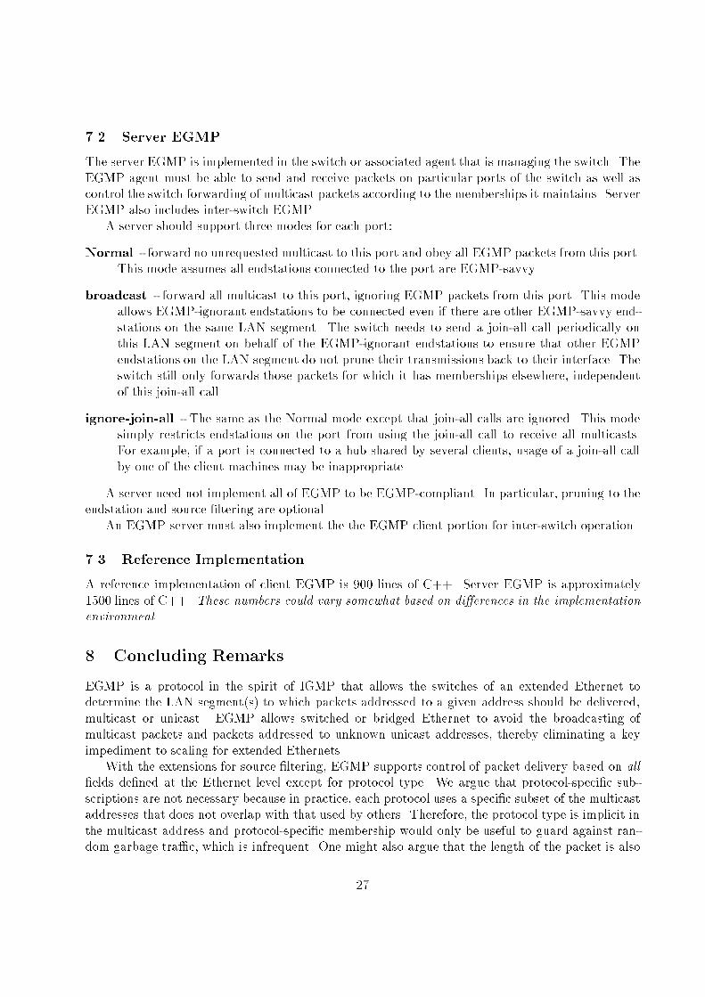
7.2 Server EGMP
The server EGMP is implemented in the switch or associated agent that is managing the switch. TheEGMP agent must be able to send and receive packets on particular ports of the switch as well ascontrol the switch forwarding of multicast packets according to the memberships it maintains. ServerEGMP also includes inter-switch EGMP.
A server should support three modes for each port:
Normal - forward no unrequested multicast to this port and obey all EGMP packets from this port.This mode assumes all endstations connected to the port are EGMP-savvy.
broadcast - forward all multicast to this port, ignoring EGMP packets from this port. This modeallows EGMP-ignorant endstations to be connected even if there are other EGMP-savvy end-stations on the same LAN segment. The switch needs to send a join-all call periodically onthis LAN segment on behalf of the EGMP-ignorant endstations to ensure that other EGMPendstations on the LAN segment do not prune their transmissions back to their interface. Theswitch still only forwards those packets for which it has memberships elsewhere, independentof this join-all call.
ignore-join-all - The same as the Normal mode except that join-all calls are ignored. This modesimply restricts endstations on the port from using the join-all call to receive all multicasts.For example, if a port is connected to a hub shared by several clients, usage of a join-all callby one of the client machines may be inappropriate.
A server need not implement all of EGMP to be EGMP-compliant. In particular, pruning to theendstation and source �ltering are optional.
An EGMP server must also implement the the EGMP client portion for inter-switch operation.
7.3 Reference Implementation
A reference implementation of client EGMP is 900 lines of C++. Server EGMP is approximately1500 lines of C++. These numbers could vary somewhat based on di�erences in the implementationenvironment.
8 Concluding Remarks
EGMP is a protocol in the spirit of IGMP that allows the switches of an extended Ethernet todetermine the LAN segment(s) to which packets addressed to a given address should be delivered,multicast or unicast. EGMP allows switched or bridged Ethernet to avoid the broadcasting ofmulticast packets and packets addressed to unknown unicast addresses, thereby eliminating a keyimpediment to scaling for extended Ethernets.
With the extensions for source �ltering, EGMP supports control of packet delivery based on all�elds de�ned at the Ethernet level except for protocol type. We argue that protocol-speci�c sub-scriptions are not necessary because in practice, each protocol uses a speci�c subset of the multicastaddresses that does not overlap with that used by others. Therefore, the protocol type is implicit inthe multicast address and protocol-speci�c membership would only be useful to guard against ran-dom garbage tra�c, which is infrequent. One might also argue that the length of the packet is also
27
available at the MAC level, but there is no clear use for �ltering based on packet length. Therefore,there seems little reason to extend EGMP further for MAC-level control.
EGMP is designed in part to support IP multicast on extended LANs. However, it can also beused for other protocols such as Appletalk, IPX, etc.
EGMP is speci�ed for Ethernet. It can be directly used with other network technologies thatuse Ethernet address formats, such as FDDI. Its design could be readily adapted to other switchednetwork technology with similar broadcast/multicast issues. The experience with ARP, which wasdesigned for other technologies but not really used for same, suggests specializing EGMP for Ethernetto avoid ARP-like \type of address" �elds. We leave it to those working with separateMAC protocolsand other network technologies to adapt EGMP if needed and so desired. Hopefully, the design ofEGMP as an RPC-generated protocol based on GMP will facilitate this adaptation.
Acknowledgment
Thanks to Jonathan Stone for his review of any earlier draft of this document and his idea of usingthe source address to identify the virtual LAN in inter-switch use of EGMP with distributed virtualLANs.
References
[1] F. Backes, \Transparent bridges for Interconnection of IEEE 802 LANs", IEEE Network, 2(1),5-9, January 1988.
[2] T. Bradley and C. Brown, Inverse Address Resolution Protocol, RFC 1293, Jan 92
[3] B. Cain, A. Thyagrajan, S. Deering, Internet Group Management Protocol, Version 3, draftRFC, private communication.
[4] D.R. Cheriton, Recursive Structuring of an RPC Protocol Architecture, Proceedings of SIG-COMM'88, ACM, Stanford, CA 1988.
[5] S. Deering and R. Sharma, Planned and Possible Changes to IGMP, Version 2, slides fromIDMR Working Group Meeting, March 1994.
[6] S. Deering, \Host Extensions for IP Multicasting", RFC 1112, Stanford, Aug. 1989.
[7] S. Deering, \Multicast Routing in a Datagram Internetwork", Ph.D. thesis, Stanford University,available as STAN-CS-92-1415, December, 1991.
[8] J. Hart, \Extending the IEEE 802.1MAC Bridge Standard to Remote Bridges", IEEE Network,2(1), 10-25, January 1988.
[9] IEEE P802.1d/D0, Draft Stanford for Tra�c Class and Dynamic Multicast Filtering Servicesin Bridged Local Area Networks (Draft Supplement to 802.1D), September 26, 1995.
[10] M. Laubach, Classical IP and ARP over ATM, RFC 1577, Jan. 1994
28
[11] J. Mogul and J. Postel, \Internet Standard Subnetting Procedure", RFC 950, Stanford Uni-versity and USC/ISI, Aug. 1985.
[12] D. Plummer, An Ethernet Address Resolution Protocol or, Converting Network Protocol Ad-dresses to 48-bit Ethernet Addresses for Transmission on Ethernet Hardware, RFC 826, Sym-bolics, Nov. 1982.
[13] J. Postel, \Multi-LAN Address Resolution", RFC 925, USC/ISI, Oct. 1984.
[14] C.Smoot and J. Quarterman, \Using ARP to implement transparent subnet gateways", RFC1027, Oct. 1987.
[15] ISO/IEC 10038 [ANSI/IEEE Std 802.1D 1993 Edition], Information Technology | Telecom-munications and information exchange between systems | Local are networks | Media accesscontrol (MAC) bridges.
[16] Sun Microsystems Inc, \XDR: External Data Representation Standard", RFC 1014, Sun Mi-crosystems Inc, June 1987.
[17] Sun Microsystems Inc, \RPC: Remote Procedure Call Protocol Speci�cation Version 2", RFC1057, Sun Microsystems Inc, June 1988.
A RPC Implementation
EGMP requires a minimal ONC RPC run-time implementation.The client RPC run-time is expected to retransmit a non-datagram call until receives a reply or
has retransmitted 5 times, with a retransmit interval of callRetransmitTime, where callRetransmit-Time is the maxDelay value used by the interrogator for the last leave-all call, or else 20 millisecondsif the former is not known. The client RPC run-time should also cause the xid �eld of each callpacket to be one greater (or more if necessary) than the previous call from this client. A responseshould be matched to the call using the xid �eld. Duplicate responses can be discarded by the callrecord being marked as discarded (or just the local variable storing the last xid value used beingincremented).
The server RPC run-time can be quite simple, recognizing that the EGMP calls are all idempotent.That is, there is no need to do duplicate suppression on calls. If a duplicate call request packet isreceived, the call can just be performed again to regenerate the response, eliminating any need tosave the response to a call for retransmission or the state and code to detect duplicates. There is alsono need to enforce the ordering of calls based on the sequence numbers, because calls are unlikely tobe reordered because they traverse a single LAN segment in general. Also, reordering of calls doesnot have a negative e�ect over the expected time intervals for MAC-level communication. That is,a leave call that was issued before a join call for the same address, but is reordered to occur later,causes the member to rejoin either in response to receiving the delayed leave call or in response tothe interrogator switch retransmitting the leave call in response to receiving the call. A join call thatis reordered to occur later than a leave call for the same address that was issued later may resultin an unwanted membership. However, this membership would be recollected in the next leave-allperiod so the inconsistency is short-lived.
29


![544 IEEE TRANSACTIONS ON MOBILE COMPUTING, VOL. 10, NO. …people.cs.vt.edu/~irchen/6204/pdf/Xiang-TMC11.pdf · Compared to Scalable Position-Based Multicast (SPBM) [20], EGMP has](https://static.documents.pub/doc/80x56/5d5a407488c99363728b5bd5/544-ieee-transactions-on-mobile-computing-vol-10-no-irchen6204pdfxiang-tmc11pdf.jpg)


