37

Discrete Event Modeling of Visually Guided Behaviors
Jana Ko�secka�, Henrik I. Christensenz & Ruzena Bajcsy�
* GRASP Laboratory
University of Pennsylvania
3401 Walnut Street, Room 301C
Philadelphia, PA 19104, USA
z Laboratory of Image Analysis
Aalborg University
Fr. Bajers Vej 7, Bldg. D1
DK-9220 Aalborg �, Denmark
February 8, 1994
Abstract
When visual behaviors are combined to provide a speci�c functionality needed for a task,
the combination is often based on heuristic rules. In this paper we show that by adopting the
Discrete Event Systems (DES) formalism for describing the interaction between visual behaviors
it is possible to provide systems which have well de�ned properties in terms of observability and
controllability. The method is in particular suited for describing the coupling between action
and perception. An introduction to the use of DES is provided and it is demonstrated how
DES are used for modeling behaviors and controlling a mobile robot equipped with a binocular
camera head and some additional sensors.
1
List of Figures
1 Two mobile agents : : : : : : : : : : : : : : : : : : : : : : : : : : : : : : : : : : : : : 25
2 Geometry of the head-eye system : : : : : : : : : : : : : : : : : : : : : : : : : : : : : 26
3 Gaze Control : : : : : : : : : : : : : : : : : : : : : : : : : : : : : : : : : : : : : : : : 27
4 Obstacle detection : : : : : : : : : : : : : : : : : : : : : : : : : : : : : : : : : : : : : 28
5 Inverse Perspective Transformation : : : : : : : : : : : : : : : : : : : : : : : : : : : : 29
6 a) Left Image; b) Map of the free space in lower resolution, dark areas correspond
to the free space; c) Right image : : : : : : : : : : : : : : : : : : : : : : : : : : : : : 30
7 Servoing or Path following : : : : : : : : : : : : : : : : : : : : : : : : : : : : : : : : : 31
8 Servoing the neck: ! and _! are the current position and velocity of the head/neck,
v and _� are the linear velocity and turning rate of the mobile base and dm is the
current estimate of the target distance : : : : : : : : : : : : : : : : : : : : : : : : : : 32
9 Composite Behavior Constraint : : : : : : : : : : : : : : : : : : : : : : : : : : : : : : 33
10 The Robuter-20 mobile robot and the on-board camera-head. : : : : : : : : : : : : : 34
11 The test scenario : : : : : : : : : : : : : : : : : : : : : : : : : : : : : : : : : : : : : : 35
12 Door recognized using grouping procedures : : : : : : : : : : : : : : : : : : : : : : : 36
13 The left and right images at the position where an obstacle is detected. The map of
the free space shown in the middle. The dark regions denote obstacles. : : : : : : : : 37
2
1 Introduction and Motivation
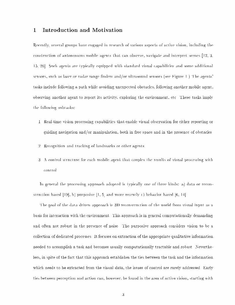
Recently, several groups have engaged in research of various aspects of active vision, including the
construction of autonomous mobile agents that can observe, navigate and interpret scenes [12, 3,
15, 26]. Such agents are typically equipped with standard visual capabilities and some additional
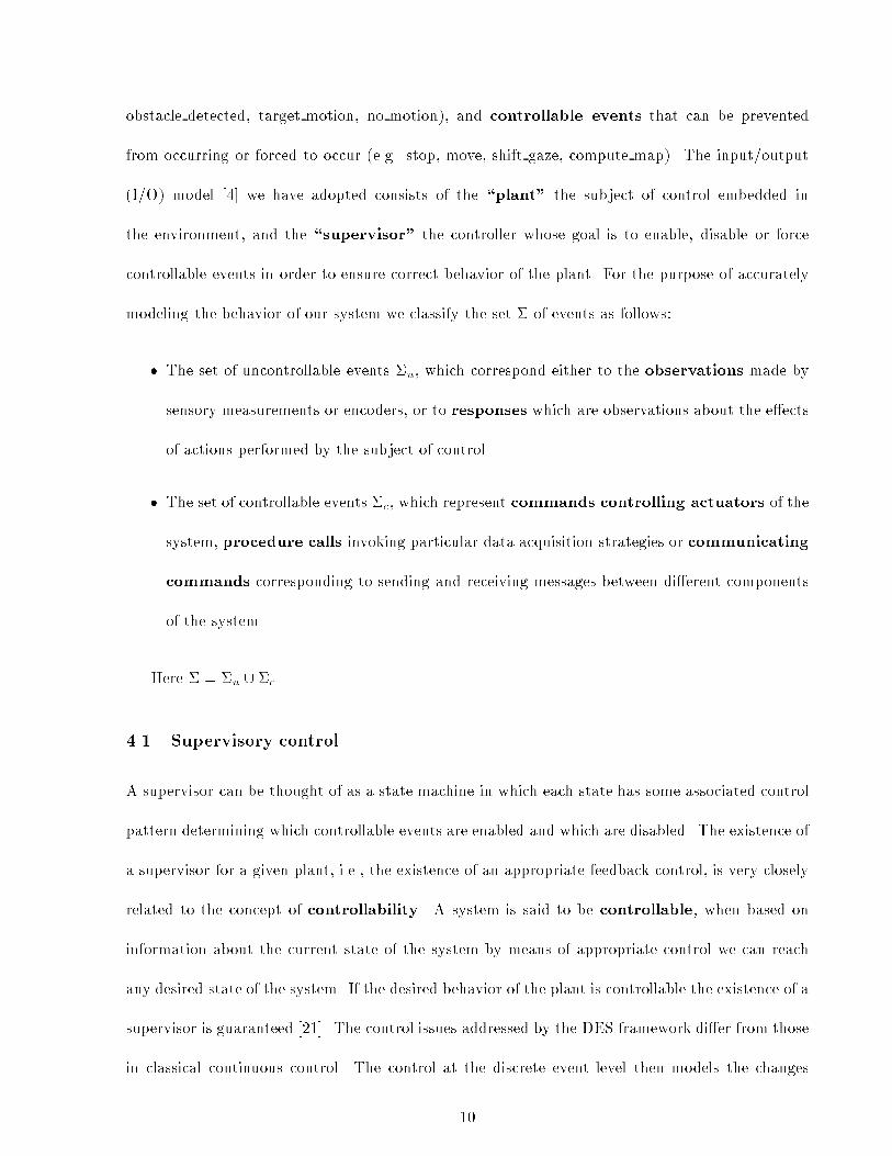
sensors, such as laser or radar range �nders and/or ultrasound sensors (see Figure 1.) The agents'
tasks include following a path while avoiding unexpected obstacles, following another mobile agent,
observing another agent to report its activity, exploring the environment, etc. These tasks imply
the following subtasks:
1. Real-time vision processing capabilities that enable visual observation for either reporting or
guiding navigation and/or manipulation, both in free space and in the presence of obstacles.
2. Recognition and tracking of landmarks or other agents.
3. A control structure for each mobile agent that couples the results of visual processing with
control.
In general the processing approach adopted is typically one of three kinds: a) data or recon-
struction based [19], b) purposive [1, 5] and more recently c) behavior based [6, 14].
The goal of the data driven approach is 3D reconstruction of the world from visual input as a
basis for interaction with the environment. This approach is in general computationally demanding
and often not robust in the presence of noise. The purposive approach considers vision to be a
collection of dedicated processes. It focuses on extraction of the appropriate qualitative information
needed to accomplish a task and becomes usually computationally tractable and robust. Neverthe-
less, in spite of the fact that this approach establishes the ties between the task and the information
which needs to be extracted from the visual data, the issues of control are rarely addressed. Early
ties between perception and action can, however, be found in the area of active vision, starting with
3
the control of intrinsic and extrinsic camera parameters. The control issues occurring in more com-
plex tasks involving navigation have been successfully accomplished using various behavior based
methods. This approach is based on the synthesis of increasingly complex functionalities through
use of a layered system architecture, in which a minimum of explicit representations are exploited.
It should be noted that the latter two approaches might exhibit scaling problems for large/general
systems [27]. An extensive discussion of the pros and cons of the three approaches can be found in
[25].
For the problem at hand the purposive approach has been adopted, where dedicated visual
capabilities are adequate for the reactive vision and landmark based navigation.
The previous success of reactive behaviors was mostly due to the fact that the coupling between
sensors and actuators was very tight and the sampling rate of the world was very high. This is no
longer the case for visual sensory data. Due to the large amount of information inherent in the
visual data we often need to select various acquisition and processing strategies to obtain the desired
qualitative information. One attempt to follow the `classical behavioralism { in the Brooksian sense'
using image data was by Horswill [14]. He used the constraints of the environment (e.g. ground
plane, color of the carpet etc.) to extract some primitives from the images which were directly
coupled with the actuators. The agent successfully moved about and was able to track arbitrary
moving objects (visitors) upon request.
We, however, would like to address more complicated behaviors/tasks where the qualitative
information is more task dependent, and together with particular control strategy, serves as \a
parameter" for agents' behavior. We will argue that having multiple parallel perception/action
processes is feasible, but in the case of systems with multiple degrees of freedom and larger variety
of tasks there is a need for a supervisory process which will guarantee the imposed safety and task
constraints. In order to achieve this goal, we model visually guided behaviors in a systematic
way using the theory of Discrete Event Systems (DES). This theory is exible enough to provide
4

tools for combining di�erent components in a modular and hierarchical fashion encompassing both
continuous and discrete aspects of our problem domain.
Overview
After describing the system, we outline our motivation for using the DES framework and brie y
introduce the supervisory control theory of DES. We then provide modeling principles which apply
to the domain of autonomous mobile agents. In the �fth section we describe gaze control, obstacle
detection and local path planning techniques, concentrating on di�erent continuous control strate-
gies employed in various situations, followed by the DES models of implemented behaviors. In
the last section we look at di�erent control strategies that can be imposed on a single behavior
as well as on the composition of more behaviors. Feasibility studies have been performed in the
laboratory environment with TRC and Robuter-20 vehicles, under varying illumination conditions
and unexpected obstacles.
2 System Description
We employ a mobile base with one rotational and two translational degrees of freedom with a
binocular camera head driven primarily by visual input. The head has pan and tilt motors and
independent control of vergence for each of the two cameras. In addition each camera is equipped
with a controllable zoom lens, focus and aperture and can be considered as an independent \eye-
module" (see Figure 10b). The components of our system and their coupling is described in more
detail below. The details of the algorithms used are elaborated on throughout the article.
Eyes The two vergence motors may be controlled to provide arbitrary vergence/version pairs (�; !)
in the range ([0; �[; ]� �2; �2[) (see Figure 2. The version angle ! is speci�ed in a neck centered
coordinate system by arctan( YX) while the vergence angle � is speci�ed by the distance to the
5

object of interest (along the version axis):
� = arccosX2 + Y 2 � B2
4q((X + B
2)2 + Y 2)((X2� B
2) + Y 2)
The optical parameters are not directly controlled here. The aperture is controlled automat-
ically, to provide a `reasonable' dynamic range in the images, and the focal-length is kept
�xed. The focus setting is driven by the vergence/version pair to keep the point de�ned by
the horopter in focus.
Neck The pan motor is driven by a PID (proportional integral derivative) controller that uses the
di�erence of vergence angles as an error measure, trying to achieve symmetric vergence for the
head. The speed of the pan motor is 10�=s while the vergence motors have a maximum speed
of 100�=s. For a given situation the eyes will initially change direction to a desired �xation
point and the neck will gradually change the setting to achieve a symmetric vergence.
The tilt motors are used to �xate at a particular distance in front or the vehicle or to enable
tracking (in depth) of a moving obstacle. They have a speed equal to the pan motor. The
tilt motors are controlled by a PID controller that is either driven by an explicit �x-point or
a moving target.
Mobile base The mobile base operates in two basic modes: point-to-point mode and go mode.
The point-to-point mode uses a trapezoidal velocity control pro�le to perform turns and
straight line moves of a speci�ed distance. The go mode moves the base in a straight
line at the current velocity setting. In this mode a continuous turn rate _� can be super-
imposed on the existing forward velocity. The state of the system is fully determined by
(xpos; ypos; �; vel; tvel;mode), where (xpos; ypos; �) is the current position and heading of
the mobile base, and vel and tvel are its current linear and turning velocity settings re-
spectively. The point-to-point mode uses position encoders (odometry) and corresponds to
6
a simple feed-forward control strategy, while motion in go mode corresponds to a feedback
control strategy servoing on an external measurement determined by perceptual processes.
The visual capabilities of our agent at the moment comprise simple obstacle detection, land-
mark/target detection and landmark/target tracking. In the rest of this section we will brie y
describe the purposive vision modules used and their coupling with the available actuators.
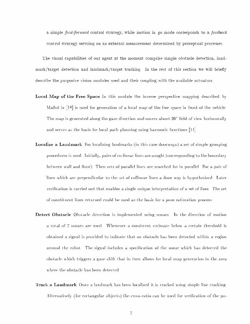
Local Map of the Free Space In this module the inverse perspective mapping described by
Mallot in [18] is used for generation of a local map of the free space in front of the vehicle.
The map is generated along the gaze direction and covers about 20� �eld of view horizontally
and serves as the basis for local path planning using harmonic functions [11].
Localize a Landmark For localizing landmarks (in this case doorways) a set of simple grouping
procedures is used. Initially, pairs of co-linear lines are sought (corresponding to the boundary
between wall and oor). Then sets of parallel lines are searched for in parallel. For a pair of
lines which are perpendicular to the set of collinear lines a door way is hypothesized. Later
veri�cation is carried out that enables a single unique interpretation of a set of lines. The set
of constituent lines returned could be used as the basis for a pose estimation process.
Detect Obstacle Obstacle detection is implemented using sonars. In the direction of motion
a total of 7 sonars are used. Whenever a consistent estimate below a certain threshold is
obtained a signal is provided to indicate that an obstacle has been detected within a region
around the robot. The signal includes a speci�cation of the sonar which has detected the
obstacle which triggers a gaze shift that in turn allows for local map generation in the area
where the obstacle has been detected.
Track a Landmark Once a landmark has been localized it is tracked using simple line tracking.
Alternatively (for rectangular objects) the cross-ratio can be used for veri�cation of the po-
7

sition of a landmark in a sequence of images. If tracking at any instance fails a signal is
provided to announce this event.
Gaze-Shift This process is a simple feed-forward process in which the eyes/neck system is con-
trolled to direct the gaze towards a new location. The new gaze position may be speci�ed in
world, platform or relative coordinates.
3 Motivation of the DES Framework
The extraction of appropriate qualitative information from sensory data allows us to develop some
simple obstacle avoidance, landmark/target following, or more general gaze control strategies. Most
of these strategies are either inherently continuous or reactive1 and may change in response to
external environmental stimuli, the task at hand, or asynchronous interactions between system
components. Based on the task we want to accomplish, we may need to invoke modules that
have con icting e�ects on the actuators of the system. In order to achieve a compact description
of the system, where di�erent tasks correspond to di�erent combinations of continuous control
strategies, we need to model particular behaviors in a systematic fashion. In our case the modeling
process is embedded in a control structure based on the theory of Discrete Event Systems (DES)
developed by Ramadge and Wonham [20]. The DES formalism models systems in terms of �nite
state automata and allows observations (the qualitative information extracted from sensory data)
and actions (commands to the actuators of the vehicle or to the actuators of the observer-system
and asynchronous interactions with the environment) to be treated in a uniform way in terms of
events. Events correspond here to the transitions between states and model discrete changes in
the system's behavior. The DES framework is suitable for investigating control-theoretic properties
of the system such as controllability and observability, which can be conveniently predicted.
1Reactive control strategy, in this context, means that the model of the plant is unknown and the control rule is
derived empirically.
8

Moreover, various visually guided behaviors can be combined in a modular and hierarchical fashion
such that the resulting behavior will be guaranteed to be controllable.
4 The DES framework
The following section is a brief introduction to the supervisory control theory of Discrete Event
Systems (DES) [20]. DES are a class of dynamic systems in which state changes asynchronously
at discrete instances of time. The DES are modeled as nondeterministic �nite state machines,
where states correspond to some continua in the task evolution and the transitions between them
are caused by events, representing qualitative changes in environment or task evolution. Let �
denote the set of events that the system can generate and/or respond to. Then event trajectories
can be thought of as strings over this �xed alphabet �. Let the subset L � �� represent all event
trajectories which are physically possible for the system and fully characterize its behavior. In
the case when the language L is regular there exists some �nite automaton, G , such that L is
generated/accepted by G . Let this automaton G be a 5-tuple
G = (Q;�; �; q0; Qm)
where
Q - is the set of all possible states,
� - is the set of all possible events
� - is the transition function � : � �Q! Q
q0 - is the initial state,
Qm - is the subset of states called marker states, Qm � Q.
In order to adjoin means of control to the system, events are classi�ed into two categories:
uncontrollable events which can be observed but cannot be prevented from occurring (e.g.
9
obstacle detected, target motion, no motion), and controllable events that can be prevented
from occurring or forced to occur (e.g. stop, move, shift gaze, compute map). The input/output
(I/O) model [4] we have adopted consists of the \plant" the subject of control embedded in
the environment, and the \supervisor" the controller whose goal is to enable, disable or force
controllable events in order to ensure correct behavior of the plant. For the purpose of accurately
modeling the behavior of our system we classify the set � of events as follows:
� The set of uncontrollable events �u, which correspond either to the observations made by
sensory measurements or encoders, or to responses which are observations about the e�ects
of actions performed by the subject of control.
� The set of controllable events �c, which represent commands controlling actuators of the
system, procedure calls invoking particular data acquisition strategies or communicating
commands corresponding to sending and receiving messages between di�erent components
of the system.
Here � = �u [ �c.
4.1 Supervisory control
A supervisor can be thought of as a state machine in which each state has some associated control
pattern determining which controllable events are enabled and which are disabled. The existence of
a supervisor for a given plant, i.e., the existence of an appropriate feedback control, is very closely
related to the concept of controllability. A system is said to be controllable, when based on
information about the current state of the system by means of appropriate control we can reach
any desired state of the system. If the desired behavior of the plant is controllable the existence of a
supervisor is guaranteed [21]. The control issues addressed by the DES framework di�er from those
in classical continuous control. The control at the discrete event level then models the changes
10

between di�erent continuous control strategies associated with states of the system triggered either
by abrupt observations or driven by di�erent tasks. The behavior of the plant can be changed
by changing the supervisor, or by changing the level of synchronization between the plant and
supervisor [24]. Below we concentrate on control strategies when the plant and supervisor are fully
synchronized, i.e., they are responsive to each other's observations and actions [4].
5 Modeling Principles
We are faced with a problem of designing elementary behaviors for an autonomous system with
multiple degrees of freedom, multiple actuators and multiple sensors. There is variety of ways
to establish perception/action pairs and derive a control law which given a sensory measurement
computes an appropriate command to the actuator. One way to approach this modeling process
would be to associate with each actuator particular process generating commands and the overall
behavior would be achieved by executing all the behaviors in parallel, where the only interactions
will be through the world. However, in order to achieve coherent behavior particular control
subsystems need to be coupled in a certain way. Certain types of coupling are task dependent,
while others change as a response to environmental stimuli. In order to be able to model these
types of interactions, behaviors share certain events.2 This essentially means that an event can be
generated by one behavior while causing a state transition and subsequent change of the control
strategy in another. The process of designing the behaviors and the amount of sharing is not unique
and requires a great deal of engineering expertise, but once �nished the model of the system gives
us the exibility to change the control strategies under supervision and guarantee the safety of the
system.
2Event sharing can in essence be viewed as a `wiring' between di�erent �nite state machines representing particular
behaviors, similar to how it occurs in the subsumption architecture.
11

Formulation of system in a DES framework
In this section we describe in detail models of two elementary behaviors using the formalism of
Discrete Event Systems (DES) and emphasize di�erent control strategies that may occur in the
execution of subtasks (1)-(3) mentioned in the introduction. For more complex tasks we propose
elementary behaviors activated in parallel and show their composition. Following the notation
introduced in the second section we model gaze control, obstacle detection and avoidance, and
path following behaviors. Throughout the �gures of DES models of particular behaviors controllable
events are drawn with full line and uncontrollable ones with dashed line.
5.1 Gaze control
The capabilities of the visual system of a mobile agent vary in terms of the visual processing
required as well as the camera parameters suitable to obtain desired qualitative information and
hence generate appropriate action. The gaze control system used currently accommodates the
following capabilities:
1. Map generation. The gaze can be shifted to a position approximately 2 meters in front of the
vehicle, while setting the version angle to 0 (parallel optical axes) in order to obtain the map
of the free space in front of the vehicle.
2. Fixation. When a landmark has been selected the gaze control system will shift the gaze and
�xate on the object.
3. Pursuit. If an obstacle is moving or a landmark is tracked during vehicle motion a \pursuit"
task is carried out.
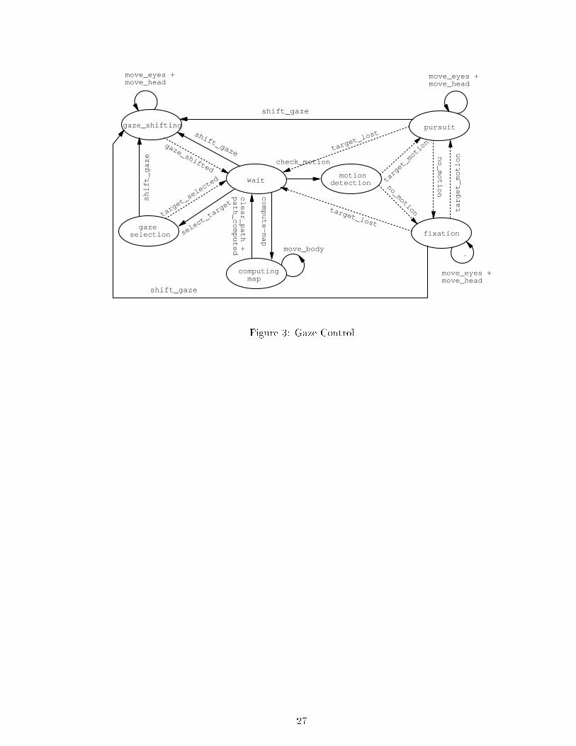
The composition of these modalities in a gaze control system is shown in Figure 3. Each of the
states are outlined below.
12
Wait The initial state of the gaze control system polls for an event to start some activity, while
some other processes can be already active (e.g. path following using dead reckoning).
Computing Map The supervisory control upon detecting an event obstacle detected forces a
computation of a map in order to determine an avoidance maneuver. To provide a map of
the free space the gaze shifts to a position in front of the vehicle after which the inverse
perspective mapping (see Section 5.2) is computed and harmonic functions are used to derive
a new path.
Gaze selection To initiate a task it is necessary to locate a landmark and to establish an initial
map of the environment, which ensures a safe path towards the goal. To accomplish this the
gaze control will carry out a gaze selection in which a landmark is localized. The landmark
recognition is, as already mentioned, based on simple perceptual grouping procedures.
Gaze shifting Once a gaze point has been determined, either by gaze selection or in response to
detection of an obstacle, the gaze shifting state controls the head in a feed-forward manner
towards a speci�ed gaze point.
Fixation If the gaze point is on a stationary target and the vehicle is at rest, a gaze selection
is followed by a �xation action which based on disparity and accommodation cues controls
focus and vergence to a local minima. The control structure applied in this state is similar to
that reported by [10] and [7]. If the platform moves during the �xation or the target begins
to move, a shift to pursuit state is performed.
Pursuit Whenever the gaze point is on a moving target a pursuit action is initiated. In this task
defocus and retinal slip are used for tracking of the target. The control strategy is based on
the model presented by [7] and later [10].
13

In gaze control a coupled strategy is used so that the vergence mechanism will initially move
to the gaze point. Any asymmetry in the vergence will the drive the version control towards a
symmetrical version angle.
5.2 Obstacle detection and avoidance
For obstacle detection we use ultrasound sensors. The obstacle detection method (see Section 2)
detects the obstacles of a size comparable to that of the vehicle quite reliably. Due to the poor
angular resolution of the sonars it is di�cult to determine the location and the extent of an obstacle;
therefore, it is di�cult to plan a smooth avoidance maneuver. For this purpose we compute the local
map of the free space in front of the vehicle. The map is computed through the di�erence between
a pair of stereo images after applying proper inverse perspective mapping [18] (see Figure 5).
Di�erences in perspective between left and right views are used to determine the presence of an
obstacle and its approximate location. When the size of the obstacle is su�ciently small compared
to the �eld of view of the agent, we use harmonic function techniques [11] to plan the path around
the obstacle. A simple feed-forward strategy is then used to follow the path. When the obstacle
is too big or possibly not stationary one way to accomplish the avoidance maneuver is in a purely
reactive manner. Based on the distance and the extent of the closest obstacle in the vehicle's path,
we compute the appropriate turning velocity _�, which is inversely proportional to the distance from
the obstacle and linear velocity of the vehicle [22].
= atan(�clearance
distance)
_� = Kt
:vel
distance
While the vehicle is steering away from the obstacle we monitor the position of the obstacle
in the �eld of view until the path in front of the obstacle is clear again (event clear path). The
reliable computation of the map of the free space requires a gaze shift towards the oor, as most
14

points would be mapped above horizon if a gaze direction parallel to the ground plane was chosen.
The appropriate camera setting will be guaranteed as the action is preceded by a shift gaze com-
mand to the gaze control process, which will be forced by the supervisor (see Section 5.4). State
computing map in Figure 3 corresponds to the strategy when the obstacle avoidance maneuver is
driven entirely by the visual information from the camera head. Note that the event move body
in this case is generated by the gaze control process, but is shared (in this case executed) by the
mobile base actuator (see Figure 7). Similar sharing occurs with the event path computed.
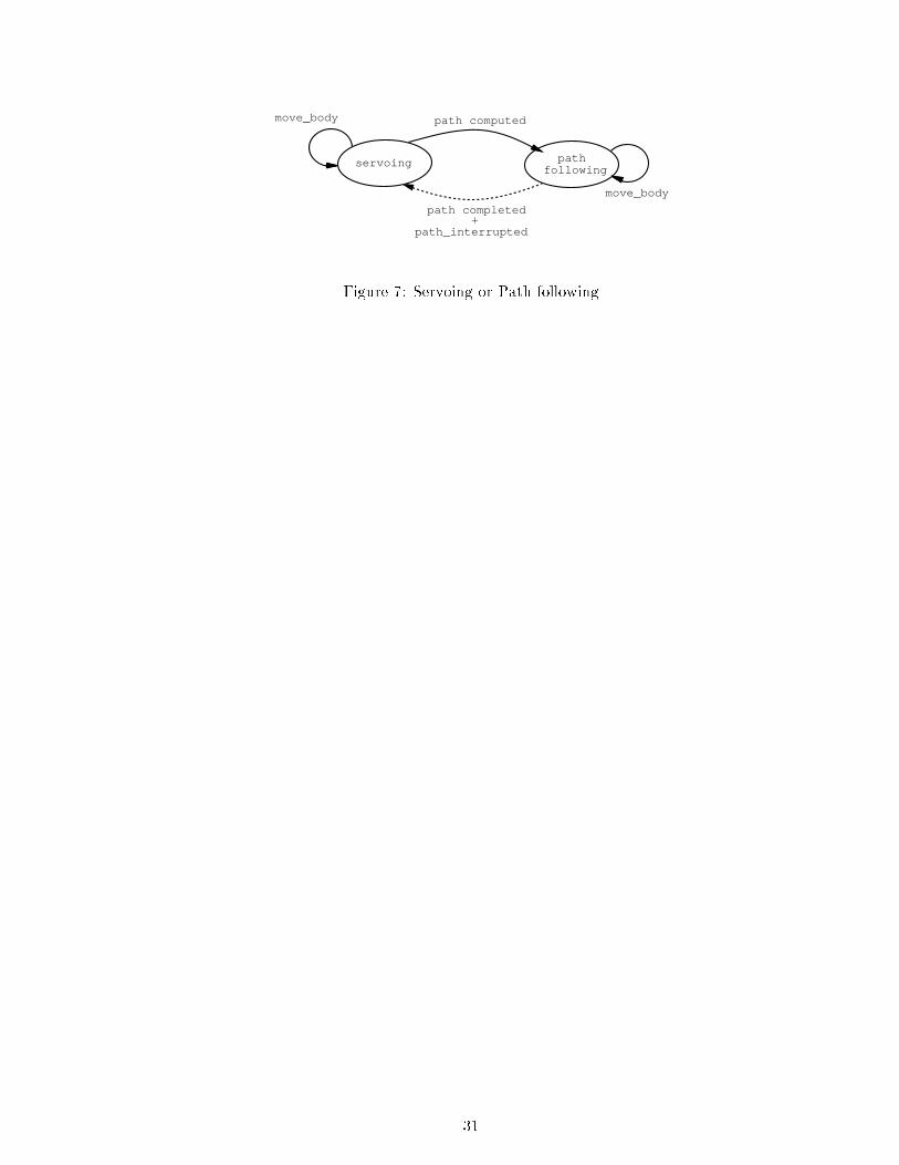
5.3 Mobile base, path following
Mobile base process operates in one of the two modes (see Figure 7):
� servoing on another perceptual process (e.g., gaze control process while pursuing, or servoing
on avoidance process if the path cannot be computed around it) and
� path following mode using simple feed-forward strategy on odometry.
Due to inaccuracies the path following this method used only locally and the rest of the time the
mobile base is driven by other perceptual processes. The control strategy applied in the state
\servoing", while tracking a target, is used to align with the neck of the system and at the same
time keep the distance to the target constant. This is accomplished by the following control rule:
_� = Kv:( _!ref � _!m) +Kp:(!ref � !m)
v = Kd:(dref � dm)
where the block diagram is in Figure 8.
The control rule for the avoidance strategy which also can be applied in this state was described
in the previous section.
15

5.4 Composite behaviors
The activation of di�erent behaviors is closely related to the task to be accomplished. Composite
behaviors are a combination of the elementary behaviors described in Section 5.
Elementary behaviors in our case are controllable either because there is only one possible
controllable event which can take place in each state or the controllable actions don't have con icting
e�ects on the actuators, partly because they are generated by one control strategy associated with
the state (e.g. events move eyes, move head in gaze control process).
However, this might not be the case for the combination of more than one behavior. Such
situations can occur when the task of the agent is to follow a given target. This task requires
an activation of both gaze control (P1), obstacle detection (P2) and path following process (P3)
(Figures 3, 4 and 7). The composition of behaviors P1, P2 and P3 results in a new behavior, P ,
which is obtained as a synchronous product
P = P1kP2kP3
of the component behaviors [21]. The component behaviors are combined in an interleaving fashion,
so the resulting behavior represents all possible sequences of events. The problems that may occur
could be related to the fact that there is a number of controllable events controling the same
actuator or a choice of control strategy may be in uenced by the state of other participating
processes. The role of supervisory control in such a case becomes crucial. The supervisor must now
ensure that the correct commands will be carried out (enabled or forced) in response to previous
observations. This situation is described in the following scenario. Once the target is detected
the gaze control behavior P1 shifts to State pursuit and continuously generates commands (events
move eyes, move head ) to keep the target in the center of the �eld of view. The mobile base is
servoing on the neck of the system (State servoing in Figure 7); obstacle detection P2 starts in
State no obstacle in the absence of obstacles and monitors the free space in front of the vehicle.
16

When the obstacle is detected (event obstacle detected) P2 makes a transition to State obstacle.
Until now the tracking process has been still in State pursuit. However, in order to determine an
appropriate avoidance maneuver we need to shift the gaze and generate the map of the free space
and compute an alternative path to follow. At this point the role of the supervisor is to force the
gaze shift event followed by compute map event, which brings P1 to State computing map. If the
path is successfully computed the gaze can be shifted back and the head can further pursue the
target. In the meantime the event path computed triggered a transition in the mobile base process
P3 which moves to State path following and remains there until the path is completed. In case
when the information about the free space is not su�cient to generate a reliable obstacle-free path,
the gaze control process remains in the state computing map and continuously generates commands
move body to steer the base around the obstacle until the path is again clear (event clear path). In
this reactive strategy for avoiding obstacles we fully employ the camera head for the computation
of the map of the free space. The control strategy of the supervisor for this particular example can
be expressed by automaton in Figure 9.
This speci�cation puts some constraints on the overall behavior ensuring that in the presence
of the obstacle and existence of path process P3 moves to path following mode and takes over
the control of the vehicle and at the same time gaze control will attempt not to lose the target.
The composition of the supervisor, given component behaviors and the composition constraint, is
described in [4, 28]. The resulting supervisor implementing above mentioned control strategy has
14 states, where three of them have associated control pattern determining which events should be
enable/disabled/forced.
17

6 Experimental Veri�cation
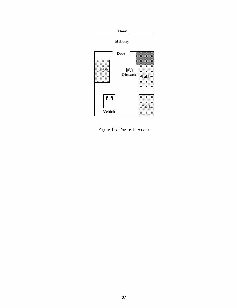
To demonstrate the concepts and methods outlined above an experiment has been carried out. In
the experiment the mobile robot moves in an indoor environment from its present position towards
a pre-speci�ed door to enter another room (see Figure 11). Motion towards the door is controlled
by the visual information received from the camera system. The door is recognized and its position
is used to drive the robot. In parallel, obstacle detection is carried out using the ultrasound sensors.
If an obstacle is detected control is shifted towards obstacle avoidance. While the robot performs
obstacle avoidance the sensory processing is concentrated on the map of the free space. By the
time the vehicle is next to the obstacle attention is shifted back to facilitate servoing on the door.
The experiment in Aalborg was carried out using a Robuter-20 mobile platform with an on-
board camera head (see Figure 10). The initial design of the robot head is described in [8, 9]. All
rotational degrees of freedom are implemented using rotational stages while the change of optical
parameters is achieved using motorized lenses.
The robot is equipped with software that allows Cartesian control of the vehicle using a simple
set of commands. For the robot head a set of PID controllers implement the control loops. The
control loops are motivated by psychological �ndings, as described by Robinson [23]. The models
are similar to those used by Clark and Ferrier [10]. The plant models account for the control of
vergence motors, where the gaze point is speci�ed in terms of vergence and version angles. For
the pan angle a simple symmetry function is used. The pan and tilt motors are on the order of
10 times slower than the camera motors; control is thus implemented using a simple proportional
controller, where
U(pan) = Kpan ��left + �right
2
Here U(pan) is the control voltage for the pan motors and Kpan is a proportionality constant. For
the tilt angle a simple PID controller is used. In the setup used here the focus setting for the
18

lenses is driven by the setting of a gaze point. During normal navigation/tracking the preferred
orientation of the vehicle is such that the pan angle with respect to the vehicle is zero.
The robot vehicle and the robot head control is coordinated through an OS/9 (real-time) com-
puter mounted on the robot. The image processing is carried out o�-board the vehicle due to power
considerations and the robot is thus connected to a stationary computer through two coaxial cables
which carry image data. The serial link is used for communication of commands to the head and
the vehicle. All image processing is carried out using standard UNIX workstations. Initially the
robot locates the door using line detection and grouping procedures which are similar to those de-
scribed by Lowe [17]. In this particular set-up the set of possible hypotheses is constrained through
introduction of contextual information that speci�es the expected size and height/width ratio for a
door. In Figure 12 the image used for recognition of a door is shown. Having recognized the door
from a binocular pair its position is estimated and the robot turns and moves towards the door.
Upon detecting the obstacle, the supervisor forces a shift gaze event followed by a computation
of the map of free space. Subsequently a new path is generated and the mobile base controller
switches from the servoing mode to the path following mode. Afterwards, attention/control is
handed over to the \door servoing" state and robot moves towards the door to leave the room.
The second experiment has been carried out in Grasp lab. The scenario is one in which the
agent (a TRC platform with 3 cameras, two of which form a �xed stereo pair and the third one is a
one degree of freedom camera with controllable pan) follows a moving target (white square). Under
this setting, the obstacle avoidance process and tracking process form separate behaviors since each
of them have separate sensors to acquire desirable visual information. As soon as an obstacle is
encountered the obstacle avoidance process takes over the control platform and the tracking process
compensates for the deviation of the target only by changing the pan angle of the camera platform.
Since there is no gaze shifting required, the constraint on the overall behavior and the supervisor
are di�erent. The DES models of this con�guration can be found in [16]. The image processing is
19

done o�-board on a SPARC-2 workstation and both the mobile base and camera pan platform are
controlled through a serial link.
We have implemented our ideas in two laboratories with di�erent system con�gurations. We
have learned what is the reasonable partitioning of the problem and how it is related to the under-
lying system con�guration. Our results suggest that the construction of the behavior models and
their independence versus coupling depends of the particular sensors/actuators setting. Since in
the experiment carried out in Aalborg the only resource for gathering of visual information is the
camera head, the type of control strategy we implemented was guaranteeing proper sequencing of
the events and subsequent interleaving of di�erent modes of gaze control process by the supervisor.
In the Grasp lab setting we had independent cameras for map generation and tracking, so these
two processes were running in parallel and supervisory control was just preventing execution of
con icting commands to the actuators (for more details see [16]).
7 Conclusions and Future Research
Visually guided behaviors have been of interest to the computer vision community for some time.
As researchers concentrated on di�erent closed-loop and real-time control [13], the role of di�er-
ent concurrent processes in robot control have become apparent [2, 6]. We believe that there is
something to be gained by investigating the system as a whole rather than its separate parts. The
examples presented are by no means a full demonstration of the capabilities of the system, but
they provide an insight to the utility of such methodologies for the the control of a mobile platform
with a camera head. While much more experimental work needs to be done, we can state that we
have con�rmed that the framework presented here, that is the mapping of sensory guided behaviors
into DES formalism is appropriate at least in the context of simple indoor environments. When
modeling the coupling between di�erent sensory and motor subsystems using DES, supervisory
20
control can guarantee successful coordination between di�erent sensory/motor processes, keeping
each of them as independent as possible but at the same time being able to accomplish desired task.
Moreover, the formalism we use allows us to systematically compose complex behaviors in a modu-
lar and hierarchical fashion and predict the controllability of the composite behaviors. The future
work will entail more sophisticated visual processing and application of the same methodology for
modeling cooperative behaviors among multiple mobile agents.
Acknowledgments: ARPA Grants N00014-92-J-1647, DAAH-0493G0419; ARO Grants DAAL03-
89-C-0031PRI, DAAL03-92-G0153; NSF Grants CISE/CDA-88-22719, CDA-9121973, CDA92-11136,
GER93-55018, IRI93-03980, IRI93-07126, NSF Grants CISE/CDA 88-22719, IRI 89-06770, and
ASC 91 0813; CEC Esprit Basic Research Project P-7108-VAP-II; and EC-US Exploratory Action
#003.
References
[1] J. Aloimonos. Purposive and qualitative active vision. In Proc. DARPA Image Understanding
Workshop, pages 816{828, 1990.
[2] Ronald. C. Arkin. Motor schema-based mobile robot navigation. In IEEE Int. Conference on
Robotics and Automation, April 1987.
[3] R. Bajcsy, V. Kumar, M. Mintz, R. Paul, and X. Yun. A small-team architecture for multiagent
robotic systems. InWorkshop on Intelligent Robotic Systems: Design and Applications, SPIE's
Intelligent Robotics Symposium, Boston, MA, November 1992.
[4] S. Balemi, G. Ho�man, P. Gyugyi, H. Wong-Toi, and G. F. Franklin. Supervisory control of a
rapid thermal multiprocessor. Technical report, Information Systems Laboratory, Department
of Electrical Engineering, Stanford University, November 1991.
21

[5] D. H. Ballard. Animate vision. Arti�cial Intelligence, 48(1):57{86, February 1991.
[6] R. A. Brooks. A robust layered control system for a mobile robot. IEEE Journal of Robotics
and Automation, RA - 2.(1):14 { 23, March 1986.
[7] R. H. S. Carpenter. Movement of the Eyes. Pion Ltd., London, second edition, April 1988.
[8] Henrik I. Christensen. The auc robot camera head. In Application of AI X: Machine Vision
and Robotics, 1992.
[9] Henrik I. Christensen. A low-cost robot camera head. Intl. Jour. of Patt. Rec. and Arti�cial
Intell., 1993.
[10] James J. Clark and Nicola Ferrier. Modal control of an attentive vision system. In R. Bajcsy
and S. Ullman, editors, Second International Conference on Computer Vision, pages 514{523.
IEEE CS Press, December 1988.
[11] Christopher I. Connolly and Roderic A. Grupen. On the application of harmonic functions to
robotics. Journal of Robotic Systems, 10(7):931 { 946, October 1993.
[12] James L. Crowley and Henrik I. Christensen. Vision as Process. ESPRIT Basic Research
Series. Springer Verlag, 1994.
[13] E. Dickmans and V. Grafe. Applications of dynamic monocular machine vision. Machine
Vision and Applications, 1:223{240, 1988.
[14] I. Horswill. A simple, cheap, and robust visual navigation system. In Proceedings: From
Animals to Animats II : Second International Conference on Simulation of Adaptive Behavior.
MIT Press 1993, 1993.
[15] J. Ko�secka and R. Bajcsy. Cooperation of visually guided behaviors. In Proceedings ICCV 93,
Berlin, Germany, May 1993.
22

[16] J. Ko�secka and R. Bajcsy. Integration of visually guided control strategies for mobile agents
with multiple sensors and actuators. submitted to ICPR-94, 1994.
[17] David G. Lowe. Perceptual Organization and Visual Recognition. Kluwer Academic Publishers,
1987.
[18] H.A. Mallot, H.H. Bultho�, J.J. Little, and S. Bohrer. Inverse perspective mapping simpli�es
optical ow computation and obstacle detection. Biological Cybernetics, 64:177{185, 1991.
[19] David Marr. Vision. W.H. Freeman and Company, New York, N.Y., 1982.
[20] P. J. Ramadge and W. M. Wonham. The control of discerete event systems. Proceedings of
the IEEE, 77(1):81{97, January 1989.
[21] P.J. Ramadge and W.M. Wonham. Supervisory control of a class of discrete event processes.
SIAM J. Contr. Optimization, 25(1):206{230, 1987.
[22] CraigW. Reynolds. Not bumping into things. In Physically Based Modelling at SIGGRAPH'88,
1988.
[23] D.A. Robinson. Why visuomotor systems don't like negative feedback and how to avoid
it. In Michael Arbib and Allan Hanson, editors, Vision, Brain and Cooperative Computing,
Computational Model of Cognition and Perception, pages 89{107, Boston, Mass., 1987. MIT
Press.
[24] Mark A. Shayman and R. Kumar. Supervisory control of nondeterministic systems with driven
events via prioritized synchronization and trajectory models. Technical report, University of
Maryland, 1992.
[25] M. Tarr and M. Black et al. Panel discussion. In Proceedings IJCAI'93, pages 1991{1666,
Chambery, France, August 1993. Morgan Kaufman.
23

[26] Massimo Tistarelli and Giulio Sandini. Dynamic aspects of active vision. CVGIP:IU, 56(1):108
{ 129, July 1992.
[27] John K. Tsotsos. Behaviourist intelligence and the scaling problem. Technical report, Dept of
Computer Science, University of Toronto, October 1993.
[28] W.M. Wonham and P.J. Ramadge. On supremable controllable sublanguage of a given lan-
guage. SIAM J. Control and Optimization, 25(3):637{639, 1987.
24
Figure 1: Two mobile agents
25

B
Y
X
21 CC
τ
ω
Figure 2: Geometry of the head-eye system
26
gazeselection
pursuitgaze_shifting
shift_gaze
fixation
computing map
move_body
wait
shift_gaze
gaze_shifted
shift_gaze n
o_motion
target_motion
move_eyes +move_head
move_eyes +move_head
move_eyes +move_head
motion detection
check_motion
select_target
clear_path +
path_computed
target
_lost
compute-map
no_motion target_motion
target_lost
shift_gaze
target_selected
Figure 3: Gaze Control
27

obstacledetected
no_obstacle obstacle
clear_path +path_computed
Figure 4: Obstacle detection
28

x
y
z
h
f
horizontal plane
f
{ W }
{ R } { L }
R
L D
b
b - baseline
D - disparity
RQ
Q
Q’
LQ’
Q
x
-x
0
0
z’
x’
y’
z’
y’
Figure 5: Inverse Perspective Transformation
29

Figure 6: a) Left Image; b) Map of the free space in lower resolution, dark areas correspond to the
free space; c) Right image
30
path computed
path completed
path following
move_body
move_body
+ path_interrupted
servoing
Figure 7: Servoing or Path following
31

P
Kp
K
dm
Σ
Σ
+
-
+ -
θ.
ω.m
ωm
drefd
v
refω
+
ω.ref Σ v
K
Σ-
Figure 8: Servoing the neck: ! and _! are the current position and velocity of the head/neck, v and
_� are the linear velocity and turning rate of the mobile base and dm is the current estimate of the
target distance
32

obstacledetected
shift_gaze compute_map path_computedclear_path +
shift_gaze
check_motion +shift_gaze +select_target
Figure 9: Composite Behavior Constraint
33
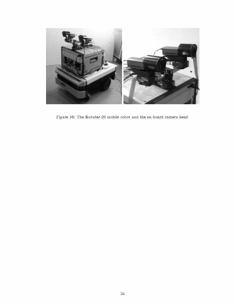
Figure 10: The Robuter-20 mobile robot and the on-board camera-head.
34
@@@@@@@@@@@@
CCCCCCCCCCCCCCCCCCCCCCCC
CCCCCCCCCCCCCCCCCCCCCCCC
CCCCCCCCCCCCCCCCCCCCCCCC
****
Vehicle
Obstacle
Door
Door
Table
Table
Table
Hallway
Figure 11: The test scenario
35

Figure 12: Door recognized using grouping procedures
36

Figure 13: The left and right images at the position where an obstacle is detected. The map of the
free space shown in the middle. The dark regions denote obstacles.
37


