10
Operation Manual www.beerinnovations.com PEGAS NovoTap, PEGAS NovoTap+

Operation Manual
www.beerinnovations.com
PEGAS NovoTap, PEGAS NovoTap+
PEG
AS
No
vo
Tap
Assem
blin
g D
iag
ram
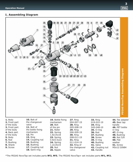
1. Assembling Diagram
10. Bolt ofthe changeovervalve11. Bolt ofthe bottle fixingmechanism12. Pin13. Ring14. Coupling nut15. Bushing16. Bushing17. Coupling nut 18. Semi-ring
mechanism20. Boltof the pin21. Roller22. Spring1.8x14x1823. Spring0.8x5.5x2224. Spring1.2x14x1525. Nut26. Nipple
19. Bottle fixing004-007-1928. Ring005-008-1929. Ring006-009-1930. Ring008-011-1931. Ring011-014-1932. Ring ofthe changeovervalve
27. Ring 33. Ring019-022-1934. Ring045-048-1935. O-ring36. Rod37. Bushing38. Screw39. O-ring40. Bushing41. Valve42. Coupling nut43. Handle
44. Tee adapter45. Beer taphandle46. PET bottleO-ring47. O-ring48. Bushing49. Nut 5/850. Flatwasher51. ScrewÌ5õ12 DIN84
1. Body2. Front partof the body3. Front partof the body4. Back partof the body5. Body6. Rod7. Bushing8. Shank9. Screw
Operation Manual ENG
*The PEGAS NovoTap set includes parts ¹3, ¹5. PEGAS NovoTap+ set includes parts ¹1, ¹2.The
3
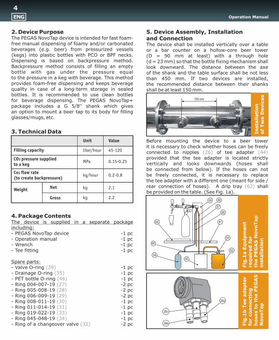
2. Device Purpose 5. Device Assembly, InstallationThe PEGAS NovoTap device is intended for fast foam- and Connectionfree manual dispensing of foamy and/or carbonated The device shall be installed vertically over a tablebeverages (e.g. beer) from pressurized vessels or a bar counter on a hollow-core beer tower(kegs) into plastic bottles with PCO or BPF necks. (D = 90 mm at least) with a through holeDispensing is based on backpressure method. (d = 23 mm) so that the bottle fixing mechanism shall Backpressure method consists of filling an empty look downward. The distance between the axebottle with gas under the pressure equal of the shank and the table surface shall be not less to the pressure in a keg with beverage. This method than 450 mm. If two devices are installed,provides foam-free dispensing and keeps beverage the recommended distance between their shanks quality in case of a long-term storage in sealed shall be at least 150 mm. bottles. It is recommended to use clean bottlesfor beverage dispensing. The PEGAS NovoTap+ package includes a G 5/8'' shank which givesan option to mount a beer tap to its body for filling glasses/mugs, etc.
3. Technical Data
Before mounting the device to a beer towerit is necessary to check whether hoses can be freely connected to nipples of tee adapter provided that the tee adapter is located strictly vertically and looks downwards (hoses shallbe connected from below). If the hoses can notbe freely connected, it is necessary to replacethe tee adapter with a different one (meant for side / rear connection of hoses). A drip tray shallbe provided on the table. (See Fig. 1a).
4. Package ContentsThe device is supplied in a separate package including: - PEGAS NovoTap device -1 pc- Operation manual -1 - Wrench -1 pc- Tee fitting -1 pc
Spare parts:- Valve O-ring -1 pc- Drainage O-ring -1 pc- PET bottle O-ring -1 pc- Ring 004-007-19 -2 pc- Ring 005-008-19 -2 pc- Ring 006-009-19 -2 pc- Ring 008-011-19 -1 pc- Ring 011-014-19 -1 pc- Ring 019-022-19 -1 pc- Ring 045-048-19 -1 pc- Ring of a changeover valve -2 pc
pc
(26) (44)
(62)
(39)(35)(46)(27)(28)(29) (30)(31)(33)(34)
(32)
Fig
.1à E
qu
ipm
en
tre
qu
ired
fo
r th
e P
EG
AS
No
vo
Tap
in
sta
llati
on
57
59 56
58
61
53
52
5554
60
62
Fig
.1b
Tee a
dap
ter
for
co
nn
ecti
ng
ho
ses t
o t
he P
EG
AS
No
vo
Tap
26a
26b
26c
Unit Value
Filling capacity
CO2 pressure suppliedto a keg
Co2
(to create backpressure)flow rate
Weight Net
Gross
liter/hour 45-120
0.15-0.25
kg/hour 0.2-0.8
kg 2.1
kg 2.2
Operation ManualENG
In
sta
llati
on
of
Tw
o D
evic
es
150 mm
4
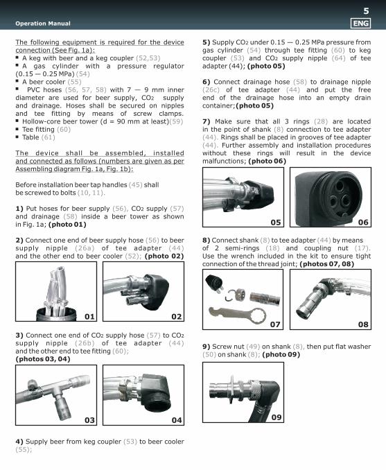
The following equipment is required for the device 5) Supply CO2 under 0.15 — 0.25 MPa pressure from connection (See Fig. 1à): gas cylinder through tee fitting to keg A keg with beer and a keg coupler coupler and CO2 supply nipple of tee A gas cylinder with a pressure regulator adapter (44); (photo 05) (0.15 — 0.25 MPa) A beer cooler 6) Connect drainage hose to drainage nipple PVC hoses with 7 — 9 mm inner of tee adapter and put the freediameter are used for beer supply, CO2 supply end of the drainage hose into an empty drain and drainage. Hoses shall be secured on nipples container;(photo 05)and tee fitting by means of screw clamps. Hollow-core beer tower (d = 90 mm at least) 7) Make sure that all 3 rings are located Tee fitting in the point of shank connection to tee adapter Table Rings shall be placed in grooves of tee adapter
Further assembly and installation procedures The device shall be assembled, installed without these rings will result in the device and connected as follows (numbers are given as per malfunctions; (photo 06)Assembling diagram Fig. 1à, Fig. 1b):
Before installation beer tap handles shallbe screwed to bolts
1) Put hoses for beer supply CO2 supply and drainage inside a beer tower as shownin Fig. 1a; (photo 01)
2) Connect one end of beer supply hose to beer 8) Connect shank to tee adapter by meanssupply nipple of tee adapter of 2 semi-rings and coupling nut and the other end to beer cooler (photo 02) Use the wrench included in the kit to ensure tight
connection of the thread joint; (photos 07, 08)
3) Connect one end of CO2 supply hose to CO2 supply nipple of tee adapter
9) Screw nut on shank then put flat washer and the other end to tee fitting
on shank (photo 09) (photos 03, 04)
4) Supply beer from keg coupler to beer cooler
(54) (60)(52,53) (53) (64)
(54)(55) (58)
(56, 57, 58) (26c) (44)
(59) (28)(60) (8)
(61) (44).(44).
(45)(10, 11).
(56), (57)(58)
(56) (8) (44)(26a) (44) (18) (17).
(52);
(57)(26b) (44)
(49) (8),(60);
(50) (8);
(53)(55);
æ
l
01 02
03 04
05 06
0807
09
Operation Manual ENG
5
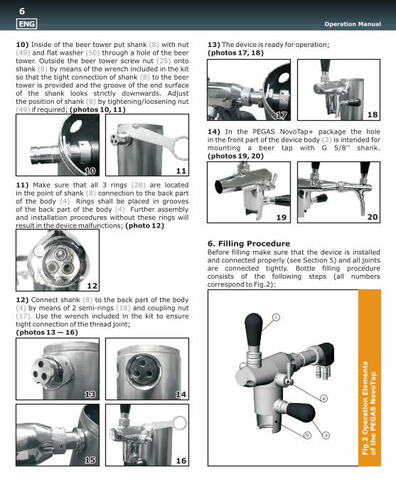
10) Inside of the beer tower put shank with nut 13) The device is ready for operation; and flat washer through a hole of the beer (photos 17, 18)
tower. Outside the beer tower screw nut onto shank by means of the wrench included in the kit so that the tight connection of shank to the beer tower is provided and the groove of the end surfaceof the shank looks strictly downwards. Adjustthe position of shank by tightening/loosening nut
if required; (photos 10, 11)
14) In the PEGAS NovoTap+ package the holein the front part of the device body is intended for mounting a beer tap with G 5/8'' shank.(photos 19, 20)
11) Make sure that all 3 rings are locatedin the point of shank connection to the back part of the body Rings shall be placed in groovesof the back part of the body Further assembly and installation procedures without these rings will result in the device malfunctions; (photo 12)
6. Filling Procedure Before filling make sure that the device is installed and connected properly (see Section 5) and all joints are connected tightly. Bottle filling procedure consists of the following steps (all numbers correspond to Fig.2):
12) Connect shank to the back part of the body by means of 2 semi-rings and coupling nut
Use the wrench included in the kit to ensure tight connection of the thread joint;(photos 13 — 16)
(8)(49) (50)
(25)(8)
(8)
(8)(49)
(2)
(28)(8)
(4).(4).
(8)(4) (18)(17).
111010
12
16
1818
1313 1414
1515
1717
Operation ManualENG
2019
Fig
.2 O
pera
tio
n E
lem
en
tso
f th
e P
EG
AS
No
vo
Tap
I
IV II
III
6
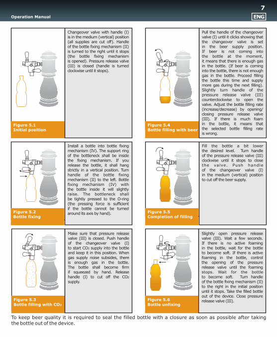
Figure 5.3Bottle filling with ÑÎ2
Make sure that pressure release valve (III) is closed. Push handle of the changeover valve (I)to start ÑÎ2 supply into the bottle and keep it in this position. When gas supply noise subsides, thereis enough gas in the bottle.The bottle shall become firmif squeezed by hand. Release handle (I) to cut off the CO2 supply.
Fill the bottle a bit lowerthe desired level. Turn handleof the pressure release valve (III) clockwise until it stops to closethe valve. Push handleof the changeover valve (I)in the medium (vertical) position to cut off the beer supply.
Figure 5.5Completion of filling
Install a bottle into bottle fixing mechanism (IV). The support ring of the bottleneck shall be inside the fixing mechanism. If you release the bottle, it shall hang strictly in a vertical position. Turn handle of the bottle fixing mechanism (II) to the left. Bottle fixing mechanism (IV) withthe bottle inside it will slightly raise. The bottleneck shallbe tightly pressed to the O-ring (the pressing force is sufficientif the bottle cannot be turned around its axis by hand).Figure 5.2
Bottle fixing
Figure 5.6Bottle unfixing
Slightly open pressure release valve (III). Wait a few seconds.If there is no active foamingin the bottle, wait for the bottleto become soft. If there is active foaming in the bottle, controlthe opening of the pressure release valve until the foaming stops. Wait for the bottleto become soft. Turn handleof the bottle fixing mechanism (II) to the right in the initial position until it stops. Take the filled bottle out of the device. Close pressure release valve (III).
Figure 5.4Bottle filling with beer
Pull the handle of the changeover valve (I) until it clicks showing thatthe changeover valve is setin the beer supply position.If beer is not coming intothe bottle at the moment,it means that there is enough gas in the bottle. (If beer is coming into the bottle, there is not enough gas in the bottle. Proceed filling the bottle this time and supply more gas during the next filling). Slightly turn handle of the pressure release valve (III) counterclockwise to open the valve. Adjust the bottle filling rate (increase/decrease) by opening/ closing pressure release valve (III). If there is much foamin the bottle, it means thatthe selected bottle filling rateis wrong.
To keep beer quality it is required to seal the filled bottle with a closure as soon as possible after takingthe bottle out of the device.
Operation Manual ENG
Figure 5.1Initial position
Changeover valve with handle (I) is in the medium (vertical) position (all supplies are cut off). Handleof the bottle fixing mechanism (II) is turned to the right until it stops(the bottle fixing mechanismis opened). Pressure release valve (III) is closed (handle is turned clockwise until it stops).
7
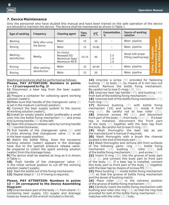
7. Device Maintenance
Only the personnel who have studied this manual and have been trained on the safe operation of the deviceare allowed to maintain the device. The device shall be maintained as shown in Table 1.
Washing procedures shall be performed as follows: 14) Unscrew a screw provided for fastening Please, PAY ATTENTION: Numbers in points bushing to body by means of 6 mm hex-nut 1 — 12 correspond to Fig. 2! wrench. Remove the bottle fixing mechanism.1) Disconnect a beer keg from the beer supply Be careful not to lose O-rings system; 15) Unscrew beer tap handle and bushing 2) Prepare a container for collecting spent working from bolt of the bottling fixing mechanism solution (water); 16) Unscrew bolt of the bottle fixing mechanism 3) Make sure that handle of the changeover valve from ring is set in the medium (vertical) position; 17) Remove bushing with 4) Connect the beer supply system to the source screw inside it fromof working solution (water); ring Be careful not to lose roller 5) Install an empty plastic bottle (preferably a small 18) Unscrew screws Ì5 and disconnectone) into the bottle fixing mechanism and press front part of the body from body If a beer it by turning handle to the left; tap is installed, disconnect the front part6) Open the pressure release valve by turning handle of the body together with the beer tap from
counterclockwise; the body. Be careful not to lose O-ring 7) Pull handle of the changeover valve until 19) Wash thoroughly the beer tap as perit clicks showing that changeover valve is set the manufacturer's manual if required;in the beer supply position; 20) Wash thoroughly with a brush the channel 8) Watch the bottle filling. Soon the excessive located in the end of the body part working solution (water) appears in the drainage 21) Wash thoroughly and remove dirt from surfaces hose due to the opened pressure release valve. of the following parts: ring bottle fixing Be prepared to collect the spent working solution mechanism bushing roller bolt(water) from the drainage hose; of the bottle fixing mechanism and screw 9) The device shall be washed as long as it is shown 22) Insert O-ring into the groove of body partin Table 1; and connect this body part to front part10) Push handle of the changeover valve of the body If a beer tap is installed, connectin the initial vertical position to cut off the working this body part to front part of the body together solution (water) supply; with the beer tap by means of screws Ì5 11) Take the bottle out of the fixing mechanism; 23) Place bushing inside bottle fixing mechanism 12) Repeat steps 2 – 11 if rinsing is required; so that the groove of bottle fixing mechanism
and the dowel of bushing match;Please, PAY ATTENTION: Numbers in points 24) Place roller in the extreme position13 — 34 correspond to the Device Assembling of the groove of bottle fixing mechanism Diagram! 25) Carefully insert the bottle fixing mechanism with 13) Unscrew back part of the body from shank bushing and roller into ring so that the ring hole containing beer supply, CO2 supply and drainage provided for bolt of the bottle fixing mechanism hoses by means of the wrench included in the kit; matches with the roller hole;
(9)(7) (5)
(28, 34);(45) (48)
(11);(11)
(I) (13);(7)
(9)(13). (21);
(51)(IV) (3) (5 or 1).
(II)(2)
(III) (28);(I)
(I)
(1);
(13),(19), (7), (21),
(11), (9);(28)
(5 or 1),(I) (3).
(2)(51);
(7)(19)
(21)(19);
(4) (8) (13)(11)
(21)
bottle fixing mechanism (19) and
Time,min.
Concentration, %
Source of workingsolution Type of washing Frequency Cleaning agent
Washing
Rinsing
Washing -desinfection
Rinsing
Rinsing
Daily after usingthe device
Weekly
After washing -desinfection
Water
Water
Water
Water
For choice:Neoseptal OS/Neomoscan Sepa/Neomoscan RD-B
10
15
10-15
15
10
20
70-85
60
40-60
20
2.01.01.0
Water pipeline
Water pipeline
Water pipeline
Water pipeline
Vessel with properfitting (washing keg)
Tab
le 1
. H
yg
ien
icM
ain
ten
an
ce P
rog
ram
for
the P
EG
AS
No
vo
Tap
Operation ManualENG
8
26) Screw bolt of the bottle fixing mechanism 10. Acceptance and sale informationinto the ring hole, make sure that there The PEGAS NovoTap i s manu fa c tu r edis no backlash if rotating parts relative to each other; in accordance with Technical Specifications27) Screw bushing and handle onto bolt ÒÓ 5131-002-48278688-04. The device has passed of the bottle fixing mechanism
the presale testing and inspection for conformance28) Place screw inside bushing
to all applicable standards and is approved good29) Put ring onto screw thread;for operation.30) Insert rings into grooves of the body
part 31) Install the assembled bottle fixing mechanism 11. Comments and claims on quality shall onto body so that the parts holes match; be sent to:32) Tighten the parts by screw using 6 mm hex- Novosibirskprodmash Co. Ltd.nut wrench; Russia, 630108, Novosibirsk, P.O. Box 175 33) Connect back part of the body to shank
Tel./fax: +7 (383) 211-90-49, containing beer supply, CO2 supply and drainage
E-mail: [email protected] by means of the wrench included in the kit;34) Remove the remaining working solution (water) from the device surface using a clean cloth.
Precautions, re-use, methods for collectingand disposal of working solution are specifiedin the manuals issued by its manufacturer.
The PEGAS NovoTap device is manufactured with high accuracy and surface condition. Duringthe operation its parts get highly adjusted to each other. It is recommended not to replace the similar parts taken from the different PEGAS NovoTap units. O-rings and movable parts of the device shallbe periodically greased with BERULUBER FR 6, BERULUBER FR 7 GSN or similar grease whichis allowed to be used in food industry.
8. PrecautionsThe following rules shall be observed to ensurethe device failure-free operation: 1) It is prohibited to use bottles which are not allowed to contact with food according to sanitary norms.2) It is prohibited to set pressure above 0.4 MPain the device.3) Only regular control of the device sanitary condition guarantees its safe and failure — free operation. Regular washing of the device is strictly required (see Section 7).
9. Warranty The manufacturer provides 12-month warranty from the date of sale and undertakes to eliminate defects arisen through the manufacturer's fault.The manufacturer bears no responsibility forthe defects resulting from the device misuse,in particular, from the absence of regular washing.The manufacturer reserves the right to modifythe device design in order to improve its consumer properties.
(11)(13)
(48) (45)(11);
(9) (7);(30) (9)
(28), (34)(5);
(5 or 1)(9)
(5) (8)
Date of manufacture:
Date of sale:
Operation Manual ENG
9
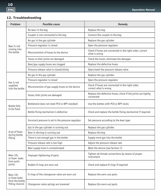
Gas is notsuppliedinto the bottle
No gas in the gas cylinder Replace the gas cylinder
Pressure regulator is closed Open the pressure regulator
Misconnection of gas supply hoses to the deviceCheck if hoses are connected in the right order,correct what is wrong
Hoses, their joints are damaged Replace the defective hoses, check if the joints are tightlyconnected
Bottleneck does not meet ÐÑÎ or BPF standard Use the bottles with PCO or BPF necks Bottle failsto be fixed
Bottle fixing mechanism is defective Check and replace the bottle fixing mechanism if required
A lot of foamduring bottlefilling
Incorrect pressure is set in the pressure regulator Set pressure according to the beer type
Gas in the gas cylinder is running out Replace the gas cylinder
Beer in the keg is running out Replace the keg
There is not enough gas in the bottle Supply more gas into the bottle
Pressure release rate is too high Adjust the pressure release rate
Beer supply hose is contaminated Wash the device (see Section 7)
Improper tightening of parts Tighten all thread connections by means of properinstrument
Beer, CO2
or foam leaksfrom partsjoints Rubber O-rings are worn out Check and replace O-rings if required
O-rings of the changeover valve are worn out Replace the worn-out partsBeer, CO2
or foam leaksfrom the bottlefilling channel Changeover valve springs are loosened Replace the worn-out parts
12. Troubleshooting
Remedy
No beer in the keg Replace the keg
Coupler is not connected to the keg Connect the coupler to the keg
No gas in the gas cylinder Replace the gas cylinder
Pressure regulator is closed Open the pressure regulator
Misconnection of hoses to the deviceCheck if hoses are connected in the right order, correctwhat is wrong
Hoses or their joints are damaged Check the hoses, eliminate the damages
Beer/gas supply hoses are clogged Replace the defective hoses
Pressure release valve is closed/sticky Open/wash the pressure release valve
Possible cause Problem
Beer is notcoming intothe bottle
Operation ManualENG
10

www.beerinnovations.com


