Congratulations on your new ALFA IN product. We are proud to have you as our customer and will strive to provide you with the best service and reliability in the industry.
This Operating Manual has been designed to instruct you on the correct use and operation of your ALFA IN product. Your satisfaction with this product and its safe operation is our ultimate concern. Therefore please take the time to read the entire manual, especially the Safety Precautions. They will help you to avoid potential hazards that may exist when working with this product.
Read and understand this entire Manual and your employer’s safety practices before installing, operating, or servicing the equipment. While the information contained in this Manual represents the Manufacturer's best judgement, the Manufacturer assumes no liability for its use.
Both models of PEGAS 160 MIG are the multi-function inverter power generators welding by those methods
a) MIG/MAG in 2T, 4T, wires SG2 or stainless steel 0,6 - 1,0 mm, Al
wires 1,0 mm, flux cored wires shelf shielding or standard. b) E – (MMA) coated electrodes up to 4,0 mm c) TIG lift arc.
2 SAFETY INSTRUCTIONS AND WARNINGS
1. Once the packing has been opened, make sure that the machine is not damaged. If in any doubt, call the service centre.
2. This equipment must only be used by qualified personnel. 3. During installation, any electric work must only be carried out by trained
personnel. 4. The machine must be used in a dry place with good ventilation. 5. Make sure that no metal dust can be drawn in by the fan inside the
machine, as this could cause damage to the electronic circuits. 6. It is prohibited to connect more than one INVERTER generator in series or
in parallel. 7. When installing the machine, follow the local regulations on safety. 8. The position of the machine must allow easy access by the operator to the
controls and connectors. 9. When the welding machine is operating, all its covers and doors must be
closed and well fixed. 10. Do not expose the welding machine to direct sunlight or to heavy rain.
This equipment conforms to protection rating IP23S. 11. During welding, the welding cables must be located near or at ground
level. They should be as short as possible. 12. The operator must wear gloves, clothes, shoes, and a helmet or a
welder’s helmet, which protect and are fire-resistant in order to protect him against electric shock, flashes and sparks from welding.
13. The operator must protect his eyes with safety visor or mask designed for welding, fitted with standard safety filters. He should also be aware that during electrical welding ULTRAVIOLET RADIATION is emitted. Therefore it is vital that his face is also protected from radiation. Ultraviolet rays produce the same harmful effect as sun burning on unprotected skin.
14. The operator is obliged to warn anyone near the welding area of the risks that welding involves and to arrange to provide adequate protection equipment.
15. It is very important to arrange for sufficient ventilation, especially when welding in enclosed spaces. We suggest using suitable fume extractors to prevent the risk of intoxication by fumes or gas generated by the welding process.
16. The operator must ensure all flammable materials are removed from the work area to avoid any risk of fire.
17. The operator must NEVER weld containers that have previously
contained petrol, lubricants, gas or similar flammable materials, even if the container has been empty for a considerable time. THERE IS A VERY HIGH RISK OF EXPLOSION.
18. The operator must be aware of all the special regulations which he needs to conform to when welding in enclosed spaces with a high risk of explosion.
19. To prevent electric shock, we strongly suggest the following rules: 20. Do not work in a damp or humid environment. 21. Do not use the welding machine if its cables are damaged in any way. 22. Make sure that the earthing system of the electric equipment is correctly
connected and operational. 23. The operator must be insulated from the metal components connected to
the return wire. 24. The earthing of the piece being worked could increase the risk of injury to
the operator. 25. EN 60974-1 Standard: Open-circuit voltage. During the operation of the
machine, the highest voltage, with which it is possible to come into contact, is the open-circuit voltage between the welding clamps. In our generator this voltage is 58V.
26. The maximum open-circuit voltage of the welding machines is established by national and international standards (EN 60974-1) depending on the type of weld current to be used, on its waveform and on the hazards arising from the work place. These values are not applicable to the strike currents and those for stabilisation of the arc that could be above it.
27. The open-circuit voltage, for as many adjustments as possible, must never exceed the values relating to the various cases shown in the following table:
Case Working conditions Open-circuit voltage
1 Places with increased risk of electric shock
DC current: 113V peak value
AC current: 68V peak value and 48V effective
2 Places without increased risk of electric shock
DC current: 113V peak value
AC current: 113V peak value and 80V effective
3 Torches held mechanically with increased protection for the operator
DC current: 141V peak value
AC current: 141V peak value and 100V effective
28. In case 1, the dc welding machines with rectifier must be built in such a way that, in case of a fault developing in the rectifier (for example open circuit, short circuit or lack of power), the permitted values cannot be exceeded. The welding machines of this type can be marked with the
symbol: S 29. Before opening the machine switch off the machine and disconnect it
from the power socket. 30. Only personnel authorised by this company can carry out maintenance
on the machine.
2.1 ELECTROMAGNETIC COMPATIBILITY (EMC)
1. This welding machine conforms to EN 60974-10 standard. However, the electromagnetic emissions generated could prove not be compatible with the maximum permitted levels for some classes of electrical equipment, such as the following:
3. Computers, robots, electro-medical instruments and life-support systems.
4. Radio-television transmitters and receivers. 5. Pacemakers and hearing aids. 6. All very sensitive electrical equipment. 7. The operator is responsible for the installation and use of the welding
machine. If there should be any fault in operations of other systems located in the immediate vicinity of the generator, we recommend suspending operations and consulting the manufacturers.
ALFA IN continuously strives to produce the best product possible and therefore reserves the right to change, improve or revise the specifications or design of this or any product without prior notice. Such updates or changes do not entitle the buyer of equipment previously sold or shipped to the corresponding changes, updates, improvements or replacement of such items.
4 EQUIPMENT
4.1 MODELS
Item No Description
5.0144-3 PEGAS 160 MIG MAN ovo-3
5.0145-4 PEGAS 160 MIG SYN ovo-4
4.2 ACCESSORIES TO ORDER
Item No. Description
BD-14040 Torch ER 140 4m EURO (MIG/MAG)
5.0155 Torch SR17 4m PEGAS 160 MAN-SYN (TIG)
VM0253 Welding Cable Set 2x 3m 35-50 160A
5.0156 Roll 0.6-0.8/1.0 Pegas MIG
4281 Valve Red.AR /CO2, 2 manometers,MINI
S777a Light Reactive Welding Helmet ALFA IN S777a GRAY
Fig . 1 PEGAS 160 MIG MAN Fig . 2 PEGAS 160 MIG SYN
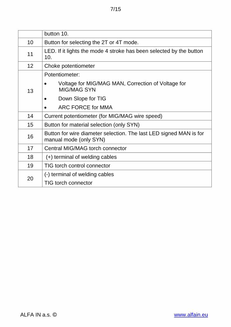
5.1 FRONT PANEL
Pos. Description
1 Display - Current
2 LED is on, when the machine is switched on by the mains switch
3 Display - Voltage
4
LED. If the LED illuminates the thermo-switch is disconnected. In such a case leave the machine on to cool down. Second function of this LED: The LED illuminates for 5 s after the machines is switched on1. During this time there is no current on the socket 18 and 20.
5 LED. If it illuminates, the method MIG/MAG has been selected by the button 8.
6 LED. If it illuminates, the method TIG has been selected by the button 8.
7 LED. If it illuminates, the method MMA has been selected by the button 8.
8 Button for selecting the welding method.
9 LED. If it illuminates the mode 2 stroke has been selected by the
Insert the mains plug into a suitable 1x230 V mains socket. The supply fuses or circuit breaker should correspond to the technical data in section 3. Switch the machine on by the ON/OFF switch (21). LED (2) and displays (1) and (3) will light on.
6.1 GETTING STARTED MMA – COATED ELECTRODE
1. Connect the electrode holder and the work lead to terminals (18) and (20) according the instructions on the electrode package.
2. NOTE Prevent touching the electrode any metal material for
in this mode the terminals (18) and (20) are under current.
3. By means of the button (8) select MMA . LED (7) will light on. 4. To select the current use potentiometer (14) 5. To select the voltage use potentiometer (13) 6. Insert the coated electrode into the electrode holder. 7. It is possible to change the level of ARC FORCE by means of
1. Fit the TIG Torch to the minus terminal (20), its connector fit to connector (19).
2. Connect the work lead to positive terminal (18) and fasten it by turning the connector to the right. Connect the work clamp to the work piece or at the welding table.
6.2.1 How to connect the gas cylinder
1. Ensure that the gas cylinder is secured to a building pillar, wall bracket or otherwise securely fixed in an upright position.
2. Open the gas valve once to blow out possible dirt particles. 3. Connect the gas regulator to the gas cylinder valve. 4. Connect the gas hose VM0321 to the gas regulator and the quick
connector fit to connector (22). 5. Open the gas cylinder valve and adjust the gas flow on the gas regulator
while pressing the torch trigger. The flow rate will be shown at the flow meter. This should be done according the table below.
6. By means of the button (8) select TIG . LED (6) will illuminate. 7. To select the current use potentiometer (14). 8. To select the slope down time use the potentiometer (13).
6.2.2 Basic settings for TIG welding – stainless steel, DC current
Material thickness
mm
Tungsten electrode diameter
mm
Filler material diameter mm
Welding current
A
Argon flow
l/min
Gas nozzle
mm
1 1 1,5 40-60 3 10
1,5 1,5 1,5 50-90 4 10
2 2 2 80-100 4 12
3 2-3 2-3 90-140 5 12
4-5 3-4 3-4 110-180 5 12
6.3 GETTING STARTED MIG/MAG
1. Fit the MIG Torch to the Euro adaptor (17) by pushing the torch connector into the brass torch adaptor and screwing the plastic torch nut clockwise to secure the torch to the torch adaptor. Remove the contact tip from the torch handset.
2. Connect the work lead to negative terminal (20) and fasten it by turning
the connector to the right. Connect the work clamp to the work piece or at the welding table.
3. Ensure that the gas cylinder is secured to a building pillar, wall bracket or otherwise securely fixed in an upright position.
4. Open the gas valve once to blow out possible dirt particles. 5. Connect the gas regulator to the gas cylinder valve. 6. Connect the gas hose VM0321 to the gas regulator and the quick
connector fit to connector (22). 7. Open the gas cylinder valve and adjust the gas flow on the gas regulator
while pressing the torch trigger. The flow rate will be shown at the flow meter. This should be approximately wire diameter x 10 l/min.
8. By means of the button (8) select MIG/MAG , LED (5) will illuminate.
9. To select 2 stroke or 4 stroke modes press button (10). Appropriate LED (9) or (11) will illuminate.
6.3.1 Model MAN setting
1. To select the current/wire speed use potentiometer (14). 2. To select the voltage use potentiometer (13). 3. To set the level of the choke use potentiometer (12). 4. To change the time of burn back (0,1 – 0,6 s) use potentiometer (33) in
the space of the wire feeder.
6.3.2 Model SYN setting
1. By means of the button (15) set the material to be welded with. (Fe – steel SG2/SG3, Al-aluminium, Ss – stainless steel).
2. By means of the button (16) set the wire diameter to be welded with. In case of setting MAN follow the instructions in the article above.
3. To set the welding power use potentiometer (14). 4. To make correction of the voltage use potentiometer (13). On position 0
is no correction. 5. To make correction of the choke level use potentiometer (12). On
position 5 is no correction. 6. To change the time of burn back (0,1 – 0,6 s) use potentiometer (33) in
the space of the wire feeder. 7. Note: The synergy curves are for PA welding position. The gas for Fe is
80% Ar+20%CO2, for Ss 98% Ar + 2% CO2, for Al 100% Ar. If you weld in different conditions it may be necessary to make correction by potentiometers (13) and (12).
6.3.3 MIG/MAG welding parameters
For orientating adjusting of the welding current and voltage you can use
empirical relation U2 = 14+0.05 2. From that you can specify desired voltage.
Wire diameter (mm) Welding current (A) Material thickness (mm)
0,6 25-110 1,0-1,6
0,8 35-160 1,0-2,3
0,9 45-160 1,0-2,3
1,0 45-160 1,2-6,0
Table of approximate parameter settings
6.3.4 Feed rolls
1. The wire feed rolls can be used for two different diameters of welding wire – the rolls have two grooves - 0,6 and 0,8-1,0 mm (The larger groove is aimed for three wire diameters 0,8-0,9 and 1,0 mm).
2. To change the groove move the Fixing Arm (38) towards you and the spring loaded pressure roll arms will pop down.
3. Unscrew the plastic Feed roll fixing (29) and take off the roll. 4. Turn the feed roll around or replace with size required. 5. The groove 0,8-1,0 mm can be used also for flux cored wires.
6.3.5 Inserting the wire
1. Open the wire feed compartment lid on the machine and un-screw the Fixing nut of the spool holder (41).
2. Place wire spool on the Spool holder body (44) and ensure that its drive dog-pin engages the mating hole in the wire spool.
3. Screw back the Fixing nut of the spool holder (41). 4. Un-screw the contact tip in the MIG torch. 5. Cut off the curved or damaged end of welding wire and feed it through the
Liner for Feeder (43). The diameter of the wire should correspond to the diameter of the feed roll. The wire size is on the face of the feed roll (28).
6. Move the Fixing Arm (38) towards you and the spring loaded pressure roll arms will pop down.
7. Thread the wire through the Liner for Feeder (43) past the rollers and then through the outlet guide in the MIG/MAG torch central connector (34).
8. Put the pressure arm roll back ensuring that it fit together and fix by setting the Fixing Arm (38) into vertical position.
9. Adjust the pressure by of Fixing Arm (38) so that it provides constant movement. Do not over tighten pressure arm setting as damage to motor gearbox may occur.
10. You may brake the spool by means of tightening nut of the spool holder (39), the wire spool should not continue to run on when the feed motor
stops. 1. Press the torch trigger till the wire appears approximately 20 mm out of the
torch neck. Screw in the contact tip corresponding to the wire diameter and cut off the wire stick out.
6.3.6 Flux core wire – setting the polarity for MIG/MAG torch
It is desirable to have positive polarity on the MIG/MAG torch while welding with solid wire in majority of cases. The welder is supplied from the production with positive polarity on the MIG/MAG torch. For welding with flux cored wires it may be necessary to have negative polarity on the MIG/MAG torch (refer to the welding wire maker´s recommendations).
1. Unscrew nut (32) and remove the cable off the terminal (+) (32). 2. Connect the cable into the (-) terminal (31) - do not leave out the washers. 3. Connect the work lead to (+) terminal of welding cables (18).
7 ROUTINE MAINTENANCE & INSPECTION
1. The only routine maintenance required for the PEGAS range of machines is a thorough cleaning and inspection, with the frequency depending on the usage and the operating environment.
2. WARNING Disconnect the PEGAS from the mains supply voltage
before disassembling. Special maintenance is not necessary for the control unit parts in the Welder. If these parts are damaged for any reason, replacement is recommended.
3. CAUTION Do not blow air into the welder during cleaning. Blowing
air into the welder can cause metal particles to interfere with sensitive electronic components and cause damage to the welder.
4. To clean the welder, disconnect it from the mains supply voltage then open the enclosure and use a vacuum cleaner to remove any accumulated dirt and dust. The welder should also be wiped clean. If necessary, solvents that are recommended for cleaning electrical apparatus may be used.
5. Troubleshooting and repairing of PEGAS welding equipment should only be carried out only by suitably qualified or competent person.
6. A ‘competent person’ must be a person who has acquired through training, qualification or experience, or a combination of them, the knowledge and skills enabling that person to safely carry out a risk assessment and repairs to the electrical equipment in question.
7. The person carrying out the servicing needs and repairs must know what to look at, what to look for and what to do.
1. In accordance with the warranty periods stated below, ALFA IN guarantees the proposed product to be free from defects in material or workmanship when operated in accordance with the written instructions as defined in this operating manual.
2. ALFA IN welding products are manufactured for use by commercial and industrial users and trained personnel with experience in the use and maintenance of electrical welding and cutting equipment.
3. ALFA IN will repair or replace, at its discretion, any warranted parts or components that fail due to defects in material or workmanship within the warranty period. The warranty period begins on the date of sale to the end user.
4. If warranty is being sought, please contact your ALFA IN product supplier for the warranty repair procedure.
5. ALFA IN warranty will not apply to: 6. Equipment that has been modified by any other party other than ALFA IN’s
own service personnel or with prior written consent obtained from ALFA IN Service Department.
7. Equipment that has been used beyond the specifications established in the operating manual.
8. Installation not in accordance with the installation/operating manual. 9. Any product that has been subjected to abuse, misuse, negligence or
accident. 10. Failure to clean and maintain (including lack of lubrication, maintenance
and protection), the machine as set forth in the operating, installation or service manual.
11. Within this operating manual are details regarding the maintenance necessary to ensure trouble free operation.
12. NOTE Warranty repairs must be performed by either an ALFA
IN Service Centre, an ALFA IN distributor or an Authorised Service Agent approved by the company ALFA IN.
9 DISPOSAL
Only for EU countries. Do not dispose of electric tools together with household waste material.
In accordance with European Council Directive 2002/96/EC on electrical and electronic equipment waste and its implementation in accordance with national law, electric tools that have reached the end of their service life must be collected separately and returned to an environmentally