34
MODEL 57046-4 owner ’ s manual

MODEL 57046-4
owner’s manual
2 • DCB M41 WIDEBODY
3 BEFORE YOU PROCEED
4 SAFETY PRECAUTIONS
7 TOOLS, SUPPLIES AND REQUIRED EQUIPMENT
8 ANATOMY OF THE DCB M41 WIDEBODY
9 QUICK START: GETTING UP TO SPEED
10 TQi RADIO & BRUSHLESS POWER SYSTEM
18 ADJUSTING THE ELECTRONIC SPEED CONTROL
20 DRIVING YOUR MODEL
22 ADJUSTING YOUR MODEL
25 MAINTAINING YOUR MODEL
27 TROUBLESHOOTING
28 TQi ADVANCED TUNING GUIDE
INTRODUCTION
The Traxxas DCB M41 Widebody raises the bar for reliable, high-performance RC boating with 50+mph speed, waterproof electronics, stable handling, and the run-after-run ruggedness you expect from Traxxas—all in a Ready-To-Race® package with stunning, factory-applied graphics. The DCB M41 Widebody is powered by the VXL-6s Marine brushless speed control and motor system, developed specifically for high-performance marine use. The long-range TQi radio system keeps you in control with switch-on-and-drive convenience. Stainless-steel trim tabs allow stable, precise handling. The machined-aluminum drive strut and rudder assembly channel brushless power directly into the water for incredible speed, aggressive cornering, and blistering acceleration that lets everyone know you’ve got the wildest ride on the water.
Please keep in mind that this boat is not a toy, and is not intended to be used by children without responsible adult supervision. This is due to the inherent dangers that are always associated with any body of water. Please respect the water and use extreme caution when launching and retrieving boats. We’re confident that you will enjoy the power, speed, and reliability that the DCB M41 Widebody has to offer.
We know you’re excited about getting your new model in the water, but it’s very important that you take some time to read through the Owners Manual. This manual contains all the necessary set-up and operating procedures that allow you to unlock the performance and potential that Traxxas engineers designed into your model. Even if you are an experienced R/C enthusiast, it’s important to read and follow the procedures in this manual.
We want you to feel confident that you own one of the best-performing models in the market and that it is backed by a team of professionals who aim to provide the highest level of factory support possible. Traxxas models are about experiencing total performance and satisfaction, not just with your model, but also with the company that stands behind it. We truly want you to enjoy your new model!
Thank you again for going with Traxxas.
Traxxas SupportTraxxas support is with you every step of the way. Refer to the next page to find out how to contact us and what your support options are.
Quick StartThis manual is designed with a Quick Start path that outlines the necessary procedures to get your model up and running in the shortest time possible. If you are an experienced R/C enthusiast you will find it helpful and fast. Be sure and read through the rest of the manual to learn about important safety, maintenance, and adjustment procedures. Turn to page 9 to begin.
REGISTERING YOUR MODELIn order to serve you better as our customer, please register your product within 10 days of your purchase online at Traxxas.com/register.
T r a x x a s . c o m / r e g i s t e r
FCC ComplianceThis device contains a module that complies with the limits for a Class B digital device as described in part 15 of the FCC rules. Operation is subject to the following two conditions: (1) This device may not cause harmful interference, and (2) this device must accept any interference received, including interference that may cause undesired operation.
The limits for a Class B digital device are designed to provide reasonable protection against harmful interference in residential settings. This product generates, uses and can radiate radio frequency energy, and, if not operated in accordance with the instructions, may cause harmful interference to radio communications. The user is cautioned that changes or modifications not expressly approved by the party responsible for compliance could void the user’s authority to operate the equipment.
Canada, Industry Canada (IC)This Class B digital apparatus complies with Canadian ICES-003 and RSS-210. This device complies with Industry Canada license exempt RSS standard(s). Operation is subject to the following two conditions: This device may not cause interference, and this device must accept any interference, including interference that may cause undesired operation of the device.
Radio Frequency (RF) Exposure StatementThis equipment complies with radio frequency exposure limits set forth by FCC and Industry Canada for an uncontrolled environment. This equipment should be installed and operated with a minimum distance of 20 centimeters between the radiator and your body or bystanders and must not be co-located or operating in conjunction with any other antenna or transmitter.
DCB M41 WIDEBODY • 3
BEFORE YOU PROCEED
Carefully read and follow all instructions in this and any accompanying materials to prevent serious damage to your model. Failure to follow these instructions will be considered abuse and/or neglect.
Before running your model, look over this entire manual and examine the model carefully. If for some reason you decide it is not what you wanted, then do not continue any further. Your hobby dealer absolutely cannot accept a model for return or exchange after it has been run.
Warnings, Helpful Hints, & Cross-ReferencesThroughout this manual, you’ll notice warnings and helpful hints identified by the icons below. Be sure to read them!
An important warning about personal safety or avoidingdamage to your model and related components.
Special advice from Traxxas to make things easier and more fun.
Refers you to a page with a related topic.
SUPPORTIf you have any questions about your model or its operation, call the Traxxas Technical Support line toll-free at: 1-888-TRAXXAS (1-888-872-9927)*
Technical support is available Monday through Friday from 8:30am to 9:00pm central time. Technical assistance is also available at Traxxas.com. You may also e-mail customer support with your question at [email protected]. Join thousands of registered members in our online community at Traxxas.com.
Traxxas offers a full-service, on-site repair facility to handle any of your Traxxas service needs. Maintenance and replacement parts may be purchased directly from Traxxas by phone or online at BuyTraxxas.com. You can save time, along with shipping and handling costs, by purchasing replacement parts from your local dealer.
Do not hesitate to contact us with any of your product support needs. We want you to be thoroughly satisfied with your new model!
SAFETY PRECAUTIONSAll of us at Traxxas want you to safely enjoy your new model. Operate your model sensibly and with care, and it will be exciting, safe, and fun for you and those around you. Failure to operate your model in a safe and responsible manner may result in property damage and serious injury. The precautions outlined in this manual should be strictly followed to help ensure safe operation. You alone must see that the instructions are followed and the precautions are adhered to.
Important Points to Remember
WARNING: Cutting Hazard. The propeller is extremely sharp and spins at high speed. To avoid cuts or other severe injury, keep fingers clear of the propeller whenever batteries are connected. Remove or keep loose articles of clothing and long hair away from the propeller when handling and running the boat.
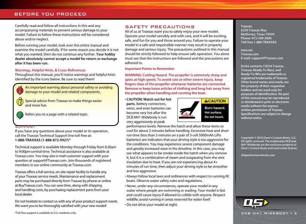
• CAUTION: Watch out for hot parts. Battery connectors, wires, and even batteries can become very hot after the DCB M41 Widebody is run very aggressively at peak performance levels. Remove the hatch and allow these items to cool for about 2 minutes before handling. Excessive heat and short run time (less than 3 minutes on a pair of 3-cell 5000mAh LiPo batteries) are indicators that your driving style is too aggressive for the conditions. You may experience severe component damage and greatly increased wear in the driveline. In this case, you may see what appears to be smoke inside the hatch when you remove it, but it is a combination of steam and outgassing from the wire insulation due to heat. If you are not experiencing about 4+ minutes of run time, then adjust your driving style to be smoother and less aggressive.
• Always follow local laws and ordinances with respect to running RC boats. Observe water safety rules and regulations.
• Never, under any circumstances, operate your model in any water where people are swimming or wading. Your model is fast and could cause injury if allowed to collide with anyone. Respect wildlife; avoid running in areas reserved for water fowl!
• Do not drive your model at night.
Traxxas6250 Traxxas WayMcKinney, Texas 75070Phone: 972-549-3000Toll-free 1-888-TRAXXAS
InternetTraxxas.comE-mail: [email protected]
Entire contents ©2016 Traxxas. Traxxas, Ready-To-Race, and Ready-To-Win are trademarks or registered trademarks of Traxxas. Other brand names and marks are the property of their respective holders and are used only for purposes of identification. No part of this manual may be reproduced or distributed in print or electronic media without the express written permission of Traxxas. Specifications are subject to change without notice.
*Toll-free support is available to U.S. residents only.
1
Copyright © 2016 Dave’s Custom Boats, LLC, All rights reserved. The trademarks DCB and M41 Widebody are the exclusive property of Dave’s Custom Boats and used under license.
dcbperformanceboats.com

4 • DCB M41 WIDEBODY
All instructions and precautions outlined in this manual should be strictly followed to ensure safe operation of your model.
1500
3600
Do not use a 6-cell 7.2V battery in combination with a
7-cell battery 8.4V pack.
1500
3600
Do not mix battery capacities. Use two batteries with the
same capacity.
This model is not intended for use by children under 14 years of age without the supervision of a responsible and knowledgeable adult. Battery choice (see LiPo Batteries, right) effects the skill level of the model. See chart below.
Batteries: Two 7-Cell NiMHVoltage*: 16.8VmAh: 3000+mAh
Batteries: Two 2S LiPoVoltage*: 14.8VmAh: 5000+mAh
Batteries: Two 3S LiPoVoltage*: 22.2VmAh: 5000+mAh
*Nominal
• Because your model is controlled by radio, it is subject to radio interference from many sources that are beyond your control. Since radio interference can cause momentary loss of radio control, always allow a safety margin in all directions around the boat in order to prevent collisions.
• Do not reach underneath the rear of your model. The propeller could spin unexpectedly. Always pick up the boat from the front or the side.
• Because of the many dangers involved with any body of water, Traxxas recommends that you never try to wade or swim to retrieve the boat. The Boat Retrieval section in this manual outlines safer, alternative methods for boat retrieval.
• Due to the high-performance nature of the electric motor, it can become hot during use. Do not touch the motor when installing and removing battery packs.
• Most importantly, use good, common sense when you are around the water to avoid mishaps, such as slipping on a muddy bank.
Speed ControlYour model’s electronic speed control (ESC) is an extremely powerful electronic device capable of delivering high current. Please closely follow these precautions to prevent damage to the speed control or other components.
• Disconnect the Battery: Always disconnect the battery or batteries from the speed control when not in use.
• Insulate the Wires: Always insulate exposed wiring with heat shrink tubing to prevent short circuits.
• Transmitter on First: Switch on your transmitter first before switching on the speed control to prevent runaways and erratic performance.
• Don’t Get Burned: The ESC and motor can become extremely hot during use, so be careful not to touch them until they cool.
• Use the Factory-Installed Connectors: Do not change the battery and motor connectors. Improper wiring can cause fire or damage to the ESC. Please note that modified speed controls can be subject to a rewiring fee when returned for service.
• No Reverse Voltage: The ESC is not protected against reverse polarity voltage.
• No Schottky Diodes: External Schottky diodes are not compatible with reversing speed controls. Using a Schottky diode with your Traxxas speed control will damage the ESC and void the 30-day warranty.
• Always adhere to the minimum and maximum limitations of the speed control as stated in the specifications table in the Owner’s Manual. If your ESC operates on two batteries, do not mix battery types and capacities. Use the same voltage and capacity for both batteries. Using mismatched battery packs could damage the batteries and electronic speed control.
Batteries and Battery ChargingYour model uses rechargeable batteries that must be handled with care for safety and long battery life. Make sure to read and follow all instructions and precautions for charging and maintaining the batteries. It is your responsibility to charge and care for the battery packs properly. In addition to your battery and charger instructions, here are some more tips to keep in mind.
• Do not charge batteries inside of an automobile. Do not charge batteries while driving in an automobile.
• Never charge batteries on wood, cloth, carpet or on any other flammable material.
• Do not operate the charger in a cluttered space, or place objects on top of the charger or battery.
• If a battery gets hot to the touch during the charging process (temperature greater than 140°F / 60°C), disconnect the battery from the charger and discontinue charging immediately.
• Always store battery packs safely out of the reach of children and pets.
• Do not short-circuit the battery pack. This may cause burns and severe damage to the battery pack and create the risk of fire.
• Do not expose the charger to water or moisture.
• Do not disassemble the charger.
• Never leave batteries to charge unattended.
• Remove the battery from the model while charging.
• Always unplug the battery from the electronic speed control when the model is not in use and when it is being stored or transported.
• Allow the battery pack to cool off between runs (before charging).
• Children should have responsible adult supervision when charging and handling batteries.
SAFETY PRECAUTIONS

DCB M41 WIDEBODY • 5
• Do not use battery packs that have been damaged in any way.
• Do not use battery packs that have damaged wiring, exposed wiring, or a damaged connector.
• Do not short-circuit the battery pack. This may cause burns and severe damage to the battery pack.
• Do not burn or puncture the batteries. Toxic materials could be released. If eye or skin contact occurs, flush with water.
• Store the battery pack in a dry location, away from heat sources and direct sunlight.
• Nickel Metal Hydride batteries must be recycled or disposed of properly.
Terms of Use:This product is surrendered by Traxxas to the purchaser with the understanding that the purchaser accepts the responsibility that driving this model and using the enclosed accessories in a careless, improper, or unsafe manner can result in serious injury or death. Also, the purchaser assumes all liability resulting from any misuse, unsafe handling, failure to follow instructions, or any action that constitutes a violation of any applicable laws or regulations. Traxxas, and all Traxxas suppliers and component makers, shall not be liable for personal injury, loss of property, or loss of life resulting from the use of this product under any circumstances, including intentional, reckless, negligent, or accidental behavior. Traxxas, and all Traxxas suppliers and component makers, shall also not be liable for any special, indirect, incidental, or consequential damages arising out of the assembly, installation, or use of their products or any accessory or chemical required to use their products. By the act of operating/using the product, the user accepts all resulting liability and releases Traxxas, and all Traxxas suppliers and component makers, of any and all liability associated with its use.
If you as the user do not accept liability of ownership, Traxxas requests that you do not use this product. Do not open any of the enclosed materials. Return the model to your hobby dealer. Your hobby dealer absolutely cannot accept an item for return or exchange after it has been run or is otherwise no longer in as-new condition.
All information contained in this guide is subject to change without notice. Traxxas reserves the right to make changes and improvements to products without incurring any obligation to incorporate such improvements into products previously sold.
If you have any questions about your model or its operation, call Traxxas Customer Support at 1-888-TRAXXAS (1-888-872-9927); outside the US, +1-972-549-3000. E-mail: [email protected].
SAFETY PRECAUTIONS

6 • DCB M41 WIDEBODY
SAFETY PRECAUTIONS
FIRE HAZARD! This product has been optimized for use with LiPo batteries and LiPo batteries are required for use with this model in its out of box configuration. Charging and discharging batteries has the potential for fire, explosion, serious injury, and property damage if not performed per the instructions. In addition, Lithium Polymer (LiPo) batteries pose a SEVERE risk of fire if not properly handled per the instructions and require special care and handling procedures for long life and safe operation. LiPo batteries are intended only for advanced users that are educated on the risks associated with LiPo battery use. Traxxas does not recommend that anyone under the age of 14 use or handle LiPo battery packs without the supervision of a knowledgeable and responsible adult. Dispose of used batteries according to the instructions.• A LiPo balance charger (such as the Traxxas EZ-Peak Dual, part #2972, sold separately) is required to charge the batteries. Consult Traxxas or your hobby dealer if you do not know what a LiPo balance charger is. NEVER USE A NiMH OR NiCAD CHARGER TO CHARGE LIPO BATTERIES AS THIS CAN CAUSE FIRE RESULTING IN PROPERTY DAMAGE, AND/OR PERSONAL INJURY OR DEATH.
• LiPo batteries have a minimum safe discharge voltage threshold that should not be exceeded. The electronic speed control is equipped with built-in Low-Voltage Detection that alerts the driver when LiPo batteries have reached their minimum voltage (discharge) threshold. It is the driver’s responsibility to stop immediately to prevent the battery pack from being discharged below its safe minimum threshold.
• Low-Voltage Detection is just one part of a comprehensive plan for safe LiPo battery use. It is critical to follow all instructions for safe and proper charging, use, and storage of LiPo batteries. Make sure you understand how to use your LiPo batteries. If you have questions about LiPo battery usage, please consult with your local hobby dealer or contact the battery manufacturer. As a reminder, all batteries should be recycled at the end of their useful life.
• ALWAYS inspect your LiPo batteries carefully before charging. Do not use or charge battery packs that have been damaged in any way (bent, dented, swollen, torn covering, or otherwise damaged).
• BEFORE you charge, ALWAYS confirm that the charger settings exactly match the type (chemistry), specification, and configuration of the battery to be charged. DO NOT exceed the maximum manufacturer recommended charge rate. DO NOT attempt to charge non-rechargeable batteries (explosion hazard), batteries that have an internal charge circuit or a protection circuit, or batteries that have been altered from original manufacturer configuration.
• While charging or discharging, ALWAYS place the battery (all types of batteries) in a fire retardant/fire proof container and on a non-flammable surface such as concrete.
• ALWAYS charge batteries in a well-ventilated area.
• Charge the battery in a safe area away from flammable materials. Monitor the charging process and never leave batteries unattended while charging. Do not allow small children to charge or handle LiPo batteries.
• DO NOT disassemble, crush, short circuit, or expose the batteries to flame or other source of ignition.
• DO NOT let any exposed battery contacts or wires touch each other. This will cause the battery to short circuit and create the risk of fire.
• DO NOT leave the charger and battery unattended while charging, discharging, or anytime the charger is ON with a battery connected. If there are any signs of a malfunction, unplug the power source and/or stop the charging process immediately.
• ALWAYS unplug the charger from the wall outlet and disconnect the battery when not in use.
• Never charge LiPo battery packs in series or parallel. Charging packs in series or parallel may result in improper charger cell recognition and an improper charging rate that may lead to overcharging, cell imbalance, cell damage and fire.
• If a battery gets hot to the touch during the charging process (temperature greater than 110°F / 43°C), immediately disconnect the battery from the charger and discontinue charging.
• DO NOT store or charge LiPo batteries with or around other batteries or battery packs of any type, including other LiPos.
• Store and transport your LiPo batteries in a cool dry place. DO NOT store in direct sunlight. DO NOT allow the storage temperature to exceed 140°F or 60°C or the cells may be damaged and risk of fire created. ALWAYS store battery packs safely out of the reach of children and pets.
• Keep a Class D fire extinguisher nearby in case of fire.
• DO NOT disassemble LiPo batteries or cells. DO NOT disassemble the charger.
• DO NOT attempt to build your own LiPo battery pack from loose cells.
• REMOVE the battery from your model or device before charging.
• DO NOT expose the charger to water or moisture.
WARNING! RISK OF FIRE, INJURY, OR DEATH

DCB M41 WIDEBODY • 7
Your model comes with a set of specialty metric tools. You’ll need to purchase other items, available from your hobby dealer, to operate and maintain your model. For more information on
batteries, see Use the Right Batteries on page 13.
Recommended EquipmentThese items are not required for the operation of your model, but are a good idea to include in any R/C toolbox:
• Safety glasses
• Traxxas Ultra Premium Tire Glue, Part #6468 (CA glue)
• Hobby knife
• Side cutters and/or needle nose pliers
• Philips screwdriver
• Soldering iron
4 AA alkaline batteries
Supplied Tools and Equipment
Required Equipment (not included)
*Battery and charger style are subject to change and may vary from images.
4-way wrench
1.5mm “L” wrench 2.0mm “T” wrench 2.5mm “T” wrench
Two 10mm motor coupler wrenchesSpare propeller
TOOLS, SUPPLIES AND REQUIRED EQUIPMENT
Battery chargerTwo 2S or 3S LiPo battery packs with
Traxxas High-Current Connectors
Boat stand (service position assembly)
Drive strut adjustment tool
Traxxas Power Cell LiPo Battery (part #2872X, sold separately)
EZ-Peak™ Dual (part #2972, sold separately)
Boat stand (display position assembly)

DCB M41 WIDEBODY OVERVIEW
Trim Tab
Stuffing Tube
Drive Strut
Drive Dog
Rudder Mount
Steering Linkage
Propeller
Propeller Nut
Rudder
Motor
Electronic Speed Control
Receiver Box
Steering Servo
Trim Tab
Rudder Mount
Propeller
Battery Strap
Battery Strap Channel
Motor Coupler
Water-Cooling JacketHull
Rudder Arm
Water-Cooling Tube
Traxxas High-Current Connector
LED Light Pipe
Flex Cable Guard
Transom

DCB M41 WIDEBODY • 9
QUICK START: GETTING UP TO SPEED
The following guide is an overview of the procedures for getting your model running. Look for the Quick Start logo on the bottom corners of Quick Start pages.
1. Read the safety precautions on page 4 6. Check servo operation • See page 16
For your own safety, understand where carelessness and misuse could lead to personal injury.
Make sure the steering servo is working correctly.
2. Charge the battery packs • See page 13 7. Range test the radio system • See page 16
Your model requires two battery packs and a compatible battery charger (not included). Never use a NiMH or NiCad charger to charge LiPo batteries.
Follow this procedure to make sure your radio system worksproperly at a distance and that there is no interference.
3. Install batteries in the transmitter • See page 13 8. Drive your DCB M41 Widebody • See page 20
The transmitter requires 4 AA alkaline batteries (sold separately). Driving tips and adjustments for your DCB M41 Widebody.
4. Install battery packs in the model • See page 14 9. Maintaining your DCB M41 Widebody • See page 25
Your model requires two full charged battery packs (not included). Follow these critical steps to maintain the performance ofyour DCB M41 Widebody and keep it in excellent running condition.
5. Turn on the radio system • See page 15
Make a habit of turning the transmitter on first, and off last.
The Quick Start Guide is not intended to replace the full operating instructions available in this manual. Please read this entire manual for complete instructions on the proper use and maintenance of your model.
Look for the Quick Start logo at the bottom of Quick Start pages.

10 • DCB M41 WIDEBODY
TQi RADIO SYSTEM & BRUSHLESS POWER SYSTEM
INTRODUCTIONYour model includes the latest Traxxas TQi transmitter with Traxxas Link™ Model Memory. The transmitter’s easy-to-use design provides instant driving fun for new R/C enthusiasts, and also offers a full compliment of pro-level tuning features for advanced users – or anyone interested in experimenting with the performance of their model. The steering and throttle channels feature adjustable Exponential, End Points, and Sub-Trims. Steering and braking Dual Rate are also available. Many of the next-level features are controlled by the Multi-Function knob, which can be programmed to control a variety functions. The detailed instructions (page 28) and Menu Tree (page 31) included in this manual will help you understand and operate the advanced functions of the new TQi radio system. For additional information and how-to videos, visit Traxxas.com.
RADIO AND POWER SYSTEM TERMINOLOGYPlease take a moment to familiarize yourself with these radio and power system terms. They will be used throughout this manual.A detailed explanation of the advanced terminology and features of your new radio system begins on page 28.
2.4GHz Spread Spectrum – This model is equipped with the latest R/C technology. Unlike AM and FM systems that require frequency crystals and are prone to frequency conflicts, the TQi system automatically selects and locks onto an open frequency, and offers superior resistance to interference and “glitching.”
BEC (Battery Eliminator Circuit) - The BEC can either be in the receiver or in the ESC. This circuit allows the receiver and servos to be powered by the main battery pack in an electric model. This eliminates the need to carry a separate pack of 4 AA batteries to power the radio equipment.
Brushless Motor - A D/C brushless motor replaces the brushed motor’s traditional commutator and brush arrangement with intelligent electronics that energize the electromagnetic windings in sequence to provide rotation. Opposite of a brushed motor, the brushless motor has its windings (coils) on the perimeter of the motor can and the magnets are mounted to the spinning rotor shaft.
Current - Current is a measure of power flow through the electronics, usually measured in amps. If you think of a wire as a garden hose, current is a measure of how much water is flowing through the hose.
ESC (Electronic Speed Control) - An electronic speed control is the electronic motor control inside the model. The VXL-6s Marine electronic speed control uses advanced circuitry to provide precise, digital proportional throttle control. Electronic speed controls use power more efficiently than mechanical speed controls so that the batteries run longer. An electronic speed control also has circuitry that prevents loss of steering and throttle control as the batteries lose their charge.
Frequency band - The radio frequency used by the transmitter to send signals to your model. This model operates on the 2.4GHz direct-sequence spread spectrum.
kV Rating - Brushless motors are often rated by their kV number. The kV rating equals no-load motor rpm with 1 volt applied. The kV increases as the number of wire turns in the motor decreases. As the kV increases, the current draw through the electronics also increases.
LiPo - Abbreviation for Lithium Polymer. Rechargeable LiPo battery packs are known for their special chemistry that allows extremely high energy density and current handling in a compact size. These are high performance batteries that require special care and handling. For advanced users only.
mAh – Abbreviation for milliamp hour. A measure of the capacity of the battery pack. The higher the number, the longer the battery will last between recharges.
Neutral position - The standing position that the servos seek when the transmitter controls are at the neutral setting.
NiCad - Abbreviation for nickel-cadmium. The original rechargeable hobby pack, NiCad batteries have very high current handling, high capacity, and can last up to 1000 charging cycles. Good charging procedures are required to reduce the possibility of developing a “memory” effect and shortened run times.
NiMH - Abbreviation for nickel-metal hydride. Rechargeable NiMH batteries offer high current handling, and much greater resistance to the “memory” effect. NiMH batteries generally allow higher capacity than NiCad batteries. They can last up to 500 charge cycles. A peak charger designed for NiMH batteries is required for optimal performance.
Receiver - The radio unit inside your model that receives signals from the transmitter and relays them to the servos.

DCB M41 WIDEBODY • 11
TQi RADIO SYSTEM & BRUSHLESS POWER SYSTEM TQi RADIO & BRUSHLESS POWER SYSTEM
Resistance - In an electrical sense, resistance is a measure of how an object resists or obstructs the flow of current through it. When flow is constricted, energy is converted to heat and is lost. The power system is optimized to reduce electrical resistance and the resulting power-robbing heat.
Rotor - The rotor is the main shaft of the brushless motor. In a brushless motor, the magnets are mounted to the rotor, and the electromagnetic windings are built into the motor housing.
Sensored - Sensored refers to a type of brushless motor that uses an internal sensor in the motor to communicate rotor position information back to the electronic speed control. The VXL-6s Marine electronic speed control is designed for use with sensorless motors.
Sensorless - Sensorless refers to a brushless motor that uses advanced instructions from an electronic speed control to provide smooth operation. Additional motor sensors and wiring are not required. The VXL-6s Marine electronic speed control is optimized for smooth sensorless control.
Servo - Small motor unit in your model that operates the steering mechanism.
Solder Tabs - Accessible, external contacts on the motor that allows for easy wire replacement.
Transmitter - The hand-held radio unit that sends throttle and steering instructions to your model.
Trim - The fine-tuning adjustment of the neutral position of the servos, made by adjusting the throttle and steering trim knobs on the face of the transmitter. Note: The Multi-Function knob must be programmed to serve as a throttle trim adjustment.
Thermal Shutdown Protection - Temperature sensing electronics used in the VXL-6s Marine electronic speed control detect overloading and overheating of the transistor circuitry. If excessive temperature is detected, the unit automatically shuts down to prevent damage to the electronics.
2-channel radio system - The TQi radio system, consisting of the receiver, the transmitter, and the servos. The system uses two channels: one to operate the throttle and one to operate the steering.
Voltage - Voltage is a measure of the electrical potential difference between two points, such as between the positive battery terminal and ground. Using the analogy of the garden hose, while current is the quantity of water flow in the hose, voltage corresponds to the pressure that is forcing the water through the hose.
IMPORTANT RADIO SYSTEM PRECAUTIONS• Do not kink the receiver’s antenna wire. Kinks in the antenna wire
will reduce range.
• DO NOT CUT any part of the receiver’s antenna wire. Cutting the antenna will reduce range.
• Extend the antenna wire in the model as far as possible for maximum range. It is not necessary to extend the antenna wire out of the body, but wrapping or coiling the antenna wire should be avoided.
• Do not allow the antenna wire to extend outside the body without the protection of an antenna tube, or the antenna wire may get cut or damaged, reducing range. It is recommended to keep the wire inside the body (in the antenna tube) to prevent the chance of damage.
To prevent loss of radio range do not kink or cut the black wire, do not bend or cut the metal tip, and do not bend or cut the white wire at the end of the metal tip.
Correct NoNo No

V/T - Voltage/Temp Sensor Port**RPM - RPM Sensor Port**BATT/CH5 - Battery/Channel 5*CH4 - Channel 4*CH3 - Channel 3*CH2 - Speed ControlCH1 - Steering ServoCH1 - Steering Servo*
* Not used ** Accessory sensor ports for use with standard voltage/temperature and RPM telemetry sensors (see Traxxas.com and included materials for more information)
12 • DCB M41 WIDEBODY
Your model is equipped with the newest Traxxas TQi transmitter with Traxxas Link™ Model Memory. The transmitter has two channels for controlling your throttle and steering. The receiver inside the model has 5 output channels. Your model is equipped with one servo and an electronic speed control.
WIRING DIAGRAM
Antenna
Receiver
Brushless Motor (see side bar for proper
motor wiring)
Channel 2Electronic Speed Control
Channel 1Steering Servo
to Motor
LED
Watercooling Output
Watercooling Input
VXL-6s MARINE ELECTRONIC SPEED CONTROL
Traxxas High-Current Connectors (Male)
to Batteries
Traxxas High-Current Connector (Male)
to Battery
Receiver Cable (RX wire)
TQi RADIO & BRUSHLESS POWER SYSTEM
ESC/Motor Wiring Diagram
TRANSMITTER AND RECEIVER
Steering Trim
Multi-Function Knob
Throttle Trigger
Throttle Neutral Adjust
Steering Wheel
Power Switch Battery Compartment
Set Button
Menu Button
Red/Green Status LEDsee page 29 for more info
Link Button
LED
Sensor Expansion Port**
**Accessory sensor expansion port for use with the Telemetry Expander Module (see Traxxas.com for more information).
DCB M41 WIDEBODY • 13
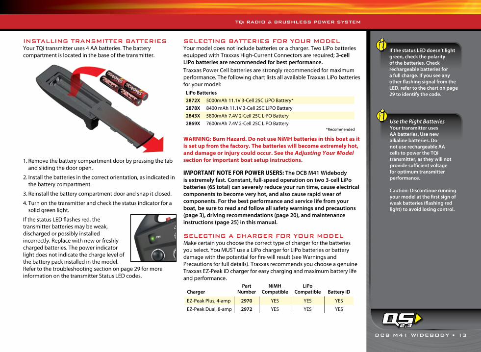
INSTALLING TRANSMITTER BATTERIESYour TQi transmitter uses 4 AA batteries. The battery compartment is located in the base of the transmitter.
1. Remove the battery compartment door by pressing the tab and sliding the door open.
2. Install the batteries in the correct orientation, as indicated in the battery compartment.
3. Reinstall the battery compartment door and snap it closed.
4. Turn on the transmitter and check the status indicator for a solid green light.
If the status LED flashes red, the transmitter batteries may be weak, discharged or possibly installed incorrectly. Replace with new or freshly charged batteries. The power indicator light does not indicate the charge level of the battery pack installed in the model. Refer to the troubleshooting section on page 29 for more information on the transmitter Status LED codes.
TQi RADIO & BRUSHLESS POWER SYSTEM
SELECTING BATTERIES FOR YOUR MODELYour model does not include batteries or a charger. Two LiPo batteries equipped with Traxxas High-Current Connectors are required; 3-cell LiPo batteries are recommended for best performance. Traxxas Power Cell batteries are strongly recommended for maximum performance. The following chart lists all available Traxxas LiPo batteries for your model:
WARNING: Burn Hazard. Do not use NiMH batteries in this boat as it is set up from the factory. The batteries will become extremely hot, and damage or injury could occur. See the Adjusting Your Model section for important boat setup instructions.
IMPORTANT NOTE FOR POWER USERS: The DCB M41 Widebody is extremely fast. Constant, full-speed operation on two 3-cell LiPo batteries (6S total) can severely reduce your run time, cause electrical components to become very hot, and also cause rapid wear of components. For the best performance and service life from your boat, be sure to read and follow all safety warnings and precautions (page 3), driving recommendations (page 20), and maintenance instructions (page 25) in this manual.
SELECTING A CHARGER FOR YOUR MODELMake certain you choose the correct type of charger for the batteries you select. You MUST use a LiPo charger for LiPo batteries or battery damage with the potential for fire will result (see Warnings and Precautions for full details). Traxxas recommends you choose a genuine Traxxas EZ-Peak iD charger for easy charging and maximum battery life and performance.
If the status LED doesn’t light green, check the polarity of the batteries. Check rechargeable batteries for a full charge. If you see any other flashing signal from the LED, refer to the chart on page 29 to identify the code.
Use the Right BatteriesYour transmitter uses AA batteries. Use new alkaline batteries. Do not use rechargeable AA cells to power the TQi transmitter, as they will not provide sufficient voltage for optimum transmitter performance.
Caution: Discontinue running your model at the first sign of weak batteries (flashing red light) to avoid losing control.
LiPo Batteries
2872X 5000mAh 11.1V 3-Cell 25C LiPO Battery*
2878X 8400 mAh 11.1V 3-Cell 25C LiPO Battery
2843X 5800mAh 7.4V 2-Cell 25C LiPO Battery
2869X 7600mAh 7.4V 2-Cell 25C LiPO Battery
ChargerPart
NumberNiMH
CompatibleLiPo
Compatible Battery iD
EZ-Peak Plus, 4-amp 2970 YES YES YES
EZ-Peak Dual, 8-amp 2972 YES YES YES
2,3
*Recommended
14 • DCB M41 WIDEBODY
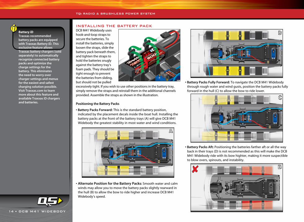
INSTALLING THE BATTERY PACKDCB M41 Widebody uses hook-and-loop straps to secure the batteries. To install the batteries, simply loosen the straps, slide the battery pack beneath them, and tighten the straps to hold the batteries snugly against the battery tray’s foam pads. They should be tight enough to prevent the batteries from sliding, but should not be pulled excessively tight. If you wish to use other positions in the battery tray, simply remove the straps and reinstall them in the additional channels provided. Assemble the straps as shown in the illustration.
Positioning the Battery Packs
• Battery Packs Forward: This is the standard battery position, indicated by the placement decals inside the boat hull. Installing the battery packs at the front of the battery trays (A) will give DCB M41 Widebody the greatest stability in most water and wind conditions.
• Alternate Position for the Battery Packs: Smooth water and calm winds may allow you to move the battery packs slightly rearward in the hull (B) to allow the bow to ride higher and increase DCB M41 Widebody’s speed.
• Battery Packs Fully Forward: To navigate the DCB M41 Widebody through rough water and wind gusts, position the battery packs fully forward in the hull (C) to allow the bow to ride lower.
• Battery Packs Aft: Positioning the batteries farther aft or all the way back in their trays (D) is not recommended as this will make the DCB M41 Widebody ride with its bow highter, making it more suspectible to blow overs, spinouts, and instability.
TQi RADIO & BRUSHLESS POWER SYSTEM
Battery iDTraxxas recommended battery packs are equipped with Traxxas Battery iD. This exclusive feature allows Traxxas battery chargers (sold separately) to automatically recognize connected battery packs and optimize the charge settings for the battery. This eliminates the need to worry over charger settings and menus for the easiest and safest charging solution possible. Visit Traxxas.com to learn more about this feature and available Traxxas iD chargers and batteries.
4
A
B
C
D✘
DCB M41 WIDEBODY • 15
5
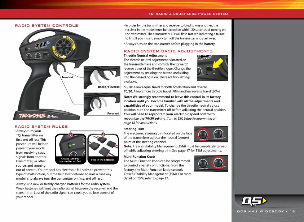
RADIO SYSTEM RULES • Always turn your
TQi transmitter on first and off last. This procedure will help to prevent your model from receiving stray signals from another transmitter, or other source, and running out of control. Your model has electronic fail-safes to prevent this type of malfunction, but the first, best defense against a runaway model is to always turn the transmitter on first, and off last.
• Always use new or freshly charged batteries for the radio system. Weak batteries will limit the radio signal between the receiver and the transmitter. Loss of the radio signal can cause you to lose control of your model.
• In order for the transmitter and receiver to bind to one another, the receiver in the model must be turned on within 20 seconds of turning on the transmitter. The transmitter LED will flash fast red indicating a failure to link. If you miss it, simply turn off the transmitter and start over.
• Always turn on the transmitter before plugging in the battery.
RADIO SYSTEM BASIC ADJUSTMENTSThrottle Neutral Adjustment The throttle neutral adjustment is located on the transmitter face and controls the forward/reverse travel of the throttle trigger. Change the adjustment by pressing the button and sliding it to the desired position. There are two settings available:
50/50: Allows equal travel for both acceleration and reverse.70/30: Allows more throttle travel (70%) and less reverse travel (30%).
Note: We strongly recommend to leave this control in its factory location until you become familiar with all the adjustments and capabilities of your model. To change the throttle neutral adjust position, turn the transmitter off before adjusting the neutral position. You will need to reprogram your electronic speed control to recognize the 70/30 setting. Turn to ESC Setup Programming on page 18 for instructions.
Steering Trim The electronic steering trim located on the face of the transmitter adjusts the neutral (center) point of the steering channel. Note: Traxxas Stability Management (TSM) must be completely turned off while adjusting steering trim. See page 17 for TSM adjustments.
Multi-Function KnobThe Multi-Function knob can be programmed to control a variety of functions. From the factory, the Multi-Function knob controls Traxxas Stability Management (TSM). For more detail on TSM, refer to page 17.
RADIO SYSTEM CONTROLS
TQi RADIO & BRUSHLESS POWER SYSTEM
Forward
Neutral
Brake/Reverse
TURN RIGH
T
TU
RN
LEFT
Always turn yourtransmitter on first.
1 2
Plug in the batteries.
16 • DCB M41 WIDEBODY
TQi RADIO & BRUSHLESS POWER SYSTEM
USING THE RADIO SYSTEMThe TQi Radio System has been pre-adjusted at the factory. The adjustment should be checked before running the model, in case of movement during shipping. Here’s how:
1. Assemble the boat stand as shown on page 7. Place the boat on the stand so that the propeller is off the ground.
WARNING: Cutting Hazard. The propeller is extremely sharp and spins at high speed. To avoid cuts or other severe injury, keep fingers clear of the propeller whenever batteries are connected. Remove or keep loose articles of clothing and long hair away from the propeller when handling and running the boat.
2. Turn the transmitter switch on. The status LED on the transmitter should be solid green (not flashing).
3. Plug the battery packs in the model into the speed control. This turns the speed control on.
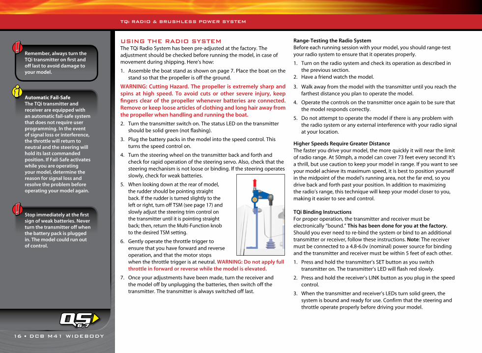
4. Turn the steering wheel on the transmitter back and forth and check for rapid operation of the steering servo. Also, check that the steering mechanism is not loose or binding. If the steering operates slowly, check for weak batteries.
5. When looking down at the rear of model, the rudder should be pointing straight back. If the rudder is turned slightly to the left or right, turn off TSM (see page 17) and slowly adjust the steering trim control on the transmitter until it is pointing straight back; then, return the Multi-Function knob to the desired TSM setting.
6. Gently operate the throttle trigger to ensure that you have forward and reverse operation, and that the motor stops when the throttle trigger is at neutral. WARNING: Do not apply full throttle in forward or reverse while the model is elevated.
7. Once your adjustments have been made, turn the receiver and the model off by unplugging the batteries, then switch off the transmitter. The transmitter is always switched off last.
Range-Testing the Radio SystemBefore each running session with your model, you should range-test your radio system to ensure that it operates properly.
1. Turn on the radio system and check its operation as described in the previous section.
2. Have a friend watch the model.
3. Walk away from the model with the transmitter until you reach the farthest distance you plan to operate the model.
4. Operate the controls on the transmitter once again to be sure that the model responds correctly.
5. Do not attempt to operate the model if there is any problem with the radio system or any external interference with your radio signal at your location.
Higher Speeds Require Greater DistanceThe faster you drive your model, the more quickly it will near the limit of radio range. At 50mph, a model can cover 73 feet every second! It’s a thrill, but use caution to keep your model in range. If you want to see your model achieve its maximum speed, it is best to position yourself in the midpoint of the model’s running area, not the far end, so you drive back and forth past your position. In addition to maximizing the radio’s range, this technique will keep your model closer to you, making it easier to see and control.
TQi Binding InstructionsFor proper operation, the transmitter and receiver must beelectronically “bound.” This has been done for you at the factory.Should you ever need to re-bind the system or bind to an additional transmitter or receiver, follow these instructions. Note: The receiver must be connected to a 4.8-6.0v (nominal) power source for binding and the transmitter and receiver must be within 5 feet of each other.
1. Press and hold the transmitter’s SET button as you switch transmitter on. The transmitter’s LED will flash red slowly.
2. Press and hold the receiver’s LINK button as you plug in the speed control.
3. When the transmitter and receiver’s LEDs turn solid green, the system is bound and ready for use. Confirm that the steering and throttle operate properly before driving your model.
Remember, always turn the TQi transmitter on first and off last to avoid damage to your model.
Automatic Fail-SafeThe TQi transmitter and receiver are equipped with an automatic fail-safe system that does not require user programming. In the event of signal loss or interference, the throttle will return to neutral and the steering will hold its last commanded position. If Fail-Safe activates while you are operating your model, determine the reason for signal loss and resolve the problem before operating your model again.
Stop immediately at the first sign of weak batteries. Never turn the transmitter off when the battery pack is plugged in. The model could run out of control.
6,7
DCB M41 WIDEBODY • 17
TQi RADIO & BRUSHLESS POWER SYSTEM
TRAXXAS STABILITY MANAGEMENT (TSM)Traxxas Stability Management or TSM makes it easier to drive your boat faster with a greater feeling of control. While turning, TSM makes minor corrections for you and allows smoother maneuvers, without intruding on your fun or creating unexpected side effects.
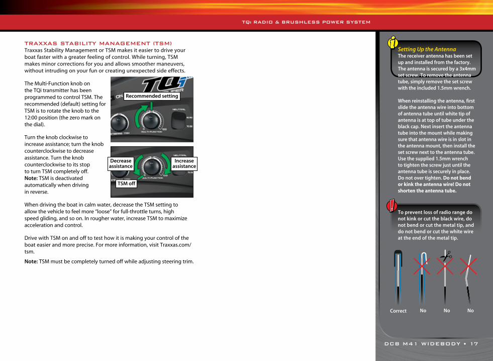
The Multi-Function knob on the TQi transmitter has been programmed to control TSM. The recommended (default) setting for TSM is to rotate the knob to the 12:00 position (the zero mark on the dial).
Turn the knob clockwise to increase assistance; turn the knob counterclockwise to decrease assistance. Turn the knob counterclockwise to its stop to turn TSM completely off. Note: TSM is deactivated automatically when driving in reverse.
When driving the boat in calm water, decrease the TSM setting to allow the vehicle to feel more “loose” for full-throttle turns, high speed gliding, and so on. In rougher water, increase TSM to maximize acceleration and control.
Drive with TSM on and off to test how it is making your control of the boat easier and more precise. For more information, visit Traxxas.com/tsm.
Note: TSM must be completely turned off while adjusting steering trim.
Setting Up the AntennaThe receiver antenna has been set up and installed from the factory. The antenna is secured by a 3x4mm set screw. To remove the antenna tube, simply remove the set screw with the included 1.5mm wrench.
When reinstalling the antenna, first slide the antenna wire into bottom of antenna tube until white tip of antenna is at top of tube under the black cap. Next insert the antenna tube into the mount while making sure that antenna wire is in slot in the antenna mount, then install the set screw next to the antenna tube. Use the supplied 1.5mm wrench to tighten the screw just until the antenna tube is securely in place. Do not over tighten. Do not bend or kink the antenna wire! Do not shorten the antenna tube.
To prevent loss of radio range do not kink or cut the black wire, do not bend or cut the metal tip, and do not bend or cut the white wire at the end of the metal tip.
Recommended setting
Decrease assistance
Increase assistance
TSM off
Correct NoNo No

18 • DCB M41 WIDEBODY
The VXL-6s Marine speed control is factory set and should not require any adjustments. These instructions are provided for your reference.
Transmitter Adjustments for the VXL-6s Marine speed controlBefore attempting to program your VXL-6s Marine electronic speed control (ESC), it is important to make sure that your transmitter is properly adjusted (set back to the factory defaults). Otherwise, you may not get the best performance from your ESC. Follow the steps below if your transmitter is not already adjusted as follows:
1. Turn transmitter off.2. Hold both MENU and SET.3. Turn transmitter on.4. Release MENU and SET. The transmitter LED will blink red.5. Press MENU once. The transmitter LED will blink red twice repeatedly.6. Press SET to clear settings. The LED will glow green and the transmitter is
restored to default.
VXL-6s Battery Settings (Low-Voltage Detection Setting)The Velineon VXL-6s Marine electronic speed control is equipped with built-in Low-Voltage Detection. The Low-Voltage Detection circuitry constantly monitors the battery voltage. When the battery voltage begins to reach the minimum recommended discharge voltage threshold for LiPo packs, the VXL-6s will limit power output to 25%. This allows sufficient power to return the model to shore. Always return your model to shore and disconnect the batteries from your model as soon as Low-Voltage Detection limits power. Refer to page 27 for important details.
The VXL-6s speed control’s Low Voltage Detection has been set for use with LiPo batteries. The speed control’s LED will glow GREEN, indicating Low Voltage Detection is activated. If you choose to run LiPo batteries in your model, Low Voltage Detection MUST be activated. Never use LiPo batteries while Low-Voltage Detection is disabled.
Verify Low-Voltage Detection setting:1. Turn on the transmitter (with the throttle at neutral).2. Connect two fully charged batteries to the VXL-6s.3. If the ESC’s LED glows red, then the Low-Voltage Detection is DISABLED
(not safe to use LiPo batteries). If the LED glows green, then Low-Voltage Detection is ACTIVATED.
To activate Low-Voltage Detection (LiPo setting):1. Turn on the transmitter and hold the trigger to full reverse.2. While holding the trigger to full reverse, connect two fully
charged batteries to the VXL-6s.3. Continue to hold reverse. After about ten seconds, the red
LED will go out and the green LED will switch on. You will also hear a ‘rising’ musical tone.
To disable Low-Voltage Detection (NiMH setting):1. Turn on the transmitter and hold the trigger to full reverse.2. While holding the trigger to full reverse, connect two fully
charged batteries to the VXL-6s.3. Continue to hold reverse. After about ten seconds, the green
LED will go out and the red LED will switch on. You will also hear a ‘falling’ musical tone.
Setup Programming (Calibrating your ESC and transmitter)Read through all of the following programming steps before you begin. If you get lost during programming or receive unexpected results, simply unplug the batteries, wait a few seconds, plug the batteries back in, and start over.
1. Place the boat on the included stand. Always make sure that objects and fingers are clear of the prop.
2. Turn on the transmitter. Pull and hold the trigger to full throttle.3. While holding full throttle, connect two fully charged battery packs to the
VXL-6s Marine ESC. It will turn on automatically.4. Continue to hold the transmitter trigger at full throttle. After about two
seconds, the ESC will beep once and its red LED will light. The full throttle position is now stored.
5. Move the trigger up to the full reverse position and hold it there. After about two seconds, you will hear two beeps and red LED will blink twice. The reverse throttle position has been stored.
6. Release the trigger so it is at the neutral position. The ESC will beep three times and the red LED will blink three times. After a short pause, the ESC will beep three more times and the LED will blink three times (red, red, green). The speed control is now programmed and ready for use.
VXL-6s Marine OperationTo operate the speed control and test the programming, place the boat on the included stand so the propeller is off the ground. Always make sure that objects and fingers are clear of the prop. 1. Turn the transmitter on.2. Connect two fully charged batteries to the ESC. It will turn on automatically.
The ESC will beep three times and blink three times (red, red, green). Note: If Low Voltage Detection is enabled, the ESC will beep once and the green LED will blink once for each cell it detects before the three blinks and beeps. For example, if you are using a 4S LiPo, the green LED will blink four times and you will hear four beeps. Then it will beep and blink three more times.
3. One LED will glow. If the red LED is glowing, it means Low-Voltage Detection has been switched off for use with NiMH batteries. The green LED will glow when Low-Voltage Detection is enabled, for use with LiPo batteries. Low-Voltage Detection must be switched on when operating the model with LiPo batteries. See the Low-Voltage Detection Setting section for more information.
4. Pull the transmitter’s trigger toward the grip to apply forward throttle. The LED will go out, then glow at full throttle.
ADJUSTING THE ELECTRONIC SPEED CONTROL
VXL-6s Marine Specifications:
Input voltage: 4.8-25.7V (6 to 18 cells NiMH or 2S to 6S LiPo)
Supported Motors: Sensorless brushless
Motor limit: None
Continuous current: 80A
Peak current : 300A
BEC voltage: 6.0V DC
Transistor type: MOSFET
Battery connector: Traxxas High-Current Connector
Motor connectors: 5.5mm bullet connectors
Motor/Battery Wiring:13-gauge cable
Protection systems: Low-Voltage Detection; Over Voltage; Thermal Overload; Throttle-Neutral Setting Protection

DCB M41 WIDEBODY • 19
5. Return the trigger to neutral and allow the prop to stop. Note that there is no programmed delay when changing from reverse to forward. Use caution to avoid slamming the speed control from reverse to forward and vice versa. This could result in driveline damage.
6. Push the trigger away from the grip to apply reverse throttle. The LED will go out, then glow at full throttle. (Note that reverse throttle is only about 15% of forward throttle. This is normal.)
7. To turn the speed control off, unplug the batteries.
Thermal Shutdown Protection The VXL-6s Marine is equipped with thermal shutdown protection to guard against overheating caused by excessive current flow. If the operating temperature exceeds safe limits, the VXL-6s Marine will automatically shut down and the ESC’s red LED will blink. The LED will continuously blink red, even if the throttle trigger is moved back and forth. After the ESC cools down to a safe level, the ESC will once again function normally.
VXL-6s Marine Profile SelectionThe speed control is factory set to Profile 1. To change the profile, follow the steps on described below. The speed control should be connected to the receiver and the transmitter should be adjusted as described previously. The profiles are selected by entering the programming mode.
VXL-6s Marine Profile Description:Profile 1 (Sport Mode): 100% Forward, 15% ReverseProfile 2 (Race Mode): 100% Forward, No ReverseProfile 3 (Training Mode): 50% Forward, 15% Reverse
Selecting Sport Mode (Profile 1)1. Place the boat on the included stand and
make sure objects and fingers are clear of the propeller.
2. Turn on the transmitter. Pull and hold the trigger to full throttle (A).
3. While holding full throttle, connect two fully charged battery packs to the VXL-6s Marine ESC (B). It will turn on automatically.
4. Continue to hold the transmitter trigger at full throttle. After about two seconds, the red LED will blink once and the ESC will beep once (C).
5. Move the trigger to neutral (D). The ESC is ready for use and is set to Profile 1.
Selecting Race Mode (Profile 2)1. Place the boat on the included stand and
make sure objects and fingers are clear of the propeller.
2. Turn on the transmitter. Pull and hold the trigger to full throttle (A).
3. While holding full throttle, connect two fully charged battery packs to the VXL-6s Marine ESC (B). It will turn on automatically.
4. Continue to hold the transmitter trigger at full throttle. After about two seconds, the red LED will blink and the ESC will beep once (C).
5. Continue to hold the transmitter trigger at full throttle. After about two more seconds (4 seconds total), the red LED will blink twice and the ESC will beep twice (D).
6. Move the trigger to neutral (E). The ESC is ready for use and is set to Profile 2.
Selecting Training Mode (Profile #3)1. Place the boat on the included stand and
make sure objects and fingers are clear of the propeller.
2. Turn on the transmitter. Pull and hold the trigger to full throttle (A).
3. While holding full throttle, connect two fully charged battery packs to the VXL-6s Marine ESC (B). It will turn on automatically.
4. Continue to hold the transmitter trigger at full throttle. After about two seconds, the red LED will blink and the ESC will beep once (C).
5. Continue to hold the transmitter trigger at full throttle. After about two more seconds (4 seconds total), the red LED will blink twice and the ESC will beep twice (D).
6. Continue to hold the transmitter trigger at full throttle. After about two more seconds (6 seconds total), the red LED will blink three times and the ESC will beep three times (E).
7. Move the trigger to neutral (F). The ESC is ready for use and is set to Profile 3.
Over-Voltage DetectionThe VXL-6s Marine speed control also detects when too much voltage is being input. If batteries with more than 25.2 volts are connected to the speed control, it will not operate. The red and green LEDs will blink, and an alternating high-low tone will sound. Unplug the batteries and install packs with 25.2 volts or less.
Throttle Neutral Protection If the transmitter’s throttle neutral position is moved after the VXL-6s speed control has been switched off, the speed control will not recognize the new position when it is turned back on and will not operate the throttle. This prevents the boat from running out of control due to an accidental change of the neutral position. If Throttle Neutral Protection detects that the throttle neutral position has changed, the VXL-6s speed control’s green LED will blink and it will beep steadily. Return the throttle trim position to neutral to resume normal throttle operation.
B
Plug in ESC
A
Full Throttle
D
Trigger Neutral
C
One Blink & Beep
B
Plug in ESC
A
Full Throttle
D
ETwo Blinks & Beeps
Trigger Neutral
C
One Blink & Beep
B
Plug in ESC
A
Full Throttle
D
F
Two Blinks & Beeps
Trigger Neutral
C
E
One Blink & Beep
Three Blinks & Beeps
ADJUSTING THE ELECTRONIC SPEED CONTROL

20 • DCB M41 WIDEBODY
Caution! If your model suddenly stops running or runs very slowly, release the throttle immediately! Refer to Troubleshooting on page 27 for more information.
Now it’s time to have some fun! This section contains instructions on driving and making adjustments to your model. Before you go on, here are some important precautions to keep in mind:• When adjusted properly, the DCB M41 Widebody should speed across the
water with the bow of the boat appearing almost level with only the rear 2-3 inches (5-7.65 cm) of the boat contacting the water. If the bow of the boat is riding high or moving up and down (porpoising) on smooth water, then the batteries may need to move forward in the boat. If the bow is low in the water and the boat is “plowing” through the waves and struggling to go fast, then the batteries may be too far forward. Only move the batteries in 1/2 inch (1.27 cm) increments at a time. Run the boat and observe if any improvement was gained. Adjustments to the strut height and angle or trim tabs can also change how the boat rides (see the Adjusting Your Model section for more information). The factory default location should work well for most situations.
• Use extra caution when traveling into the wind and/or against the direction of waves. The added pitch motion caused by driving into cresting waves, combined with wind blasts, tends to lift the boat out of the water further and might cause the boat to blow over backwards.
• If the boat starts getting very light on the water (about to blow over), reduce throttle to settle the hull back into the water.
• Always be ready to reduce the throttle if your model appears to be unstable or “chine walking” (rocking violently from side to side). Make trim tab or battery placement changes to reduce chine walking, as this behavior can cause a crash in rougher water.
• Reduce your speed in rough water. The DCB M41 Widebody does not require a glass smooth surface and is able to handle some amount of choppy water. When running across waves, increase your speed gradually to see how the boat performs and whether adjustment is needed to increase stability.
• The DCB M41 Widebody is designed to carve high-speed turns. Explore fast turns by gradually building speed until you become accustomed to the handling characteristics of the boat. You will be able to turn faster on smoother water. Slow down if the water is less smooth. Be cautious when turning into the wind. Once the boat has begun leaning into the corner, increase throttle to maintain speed and keep the bow up. To prevent spin outs, avoid steering sharply at high speed.
• Use caution when driving parallel to waves or wind chop. The waves will cause excess rocking, and may cause the boat to spin out or crash unexpectedly.
• When traveling at high speeds (40+ mph), be very gentle with control inputs to avoid hooking or flipping the boat.
• Do not operate the boat continuously at low speeds when using LiPo batteries. The ESC and motor could overheat from lack of cooling water flow.
• Monitor the water cooling system. If the stream of water exiting the cooling system on the left side of the boat is not flowing properly, inspect the system immediately for blockages. Disconnect the cooling line at the rudder and clear any obstructions.
• Avoid reversing for more than a few seconds at a time. Reversing causes water to rush over the stern of the boat and may cause it to sink.
• Drain the boat after every run. Even though every precaution has been made to keep water out of the hull, it may be necessary to drain any ingested water. Excess water in the hull will hurt performance and unbalance the boat.
• Do not leave the boat sitting in the water after each run. Water could enter the boat if the stuffing tube seal is worn.
• Remove the propeller for transportation to avoid accidentally breaking it.• Do not lift the boat by grabbing the sides of the hatch opening. This may
cause the upper hull to tear. Use two hands to lift or handle the boat, grabbing the sides of the hull about 1/3 of the way up from the back.
• Jumping your model or towing anything with it should not be attempted.• Return your model to shore at the first sign of weak batteries. Your model
will begin to slow and the controls will become sluggish.
IMPORTANT NOTES FOR POWER USERS• Slow down while you turn. Turning causes more drag on the boat and
greatly increases the electrical load on the power system. Constant high-speed turning will severely reduce your run time. In extreme cases, electrical components will become very hot and you could even damage your batteries. This is especially important to note on very smooth water where the DCB M41 Widebody will be able to turn very quickly. Maneuvers such as SUSTAINED full-throttle ovals and “figure-eights” are NOT recommended.
• Vary your speed. Do not drive the boat at full throttle for the entire duration of the battery’s charge. For maximum performance, drive at full throttle in a straight line to experience the 50+mph speed. Reduce throttle and speed while turning and then accelerate smoothly to top speed as you straighten out the steering. This will significantly increase run time and protect your batteries and electronics from excessive heat and possible damage.
• Look and listen for changes in performance. If the sound or the performance of the DCB M41 Widebody suddenly changes, immediately bring the boat back to shore for inspection. A damaged propeller (cracked or chipped) or debris caught in the driveline could be the cause. Make sure you disconnect the batteries before inspecting the boat.
CavitationIf your model is running at full throttle but is only barely moving forward, the propeller is cavitating. Try advancing the throttle slowly to get your model on plane. If you are having trouble with cavitation, check the propeller for nicks or tangled debris. Your model’s propeller is specially designed for its application and is very sensitive to any changes or modifications. If a prop is damaged, it should be replaced.
DRIVING YOUR MODEL
8

DCB M41 WIDEBODY • 21
Where to RunSelect a body of fresh water that is calm and free of debris, tree stumps, moss, fishing line, and other things that can get tangled up in the prop. The water must be at least 10 inches (25 cm) deep. Be aware that some ponds restrict the use of model boats. Avoid swimmers and other boats. Do not attempt to run the DCB M41 Widebody in an area where there are people swimming or wading. Do not run the model where it can interfere with boat traffic of any kind. Avoid disrupting fishing activities. Also, find a clean, stable area of shoreline as a launch site. Avoid locations that are steep and slippery near the edge of the water. Be mindful of the many hazards that are associated with any body of water. The boat belongs in the water, not the driver. The DCB M41 Widebody can accelerate from a stop and does not have to be hand launched or thrown into the water. Gently place the boat in the water and accelerate slowly from the bank until you are in open water. Always choose a launch location where the wind and waves will blow the boat back to the shore if there is ever a problem that prevents the boat from driving back to you. If the wind is blowing strongly, then you will need to reduce your speed while running into the wind to prevent the boat from blowing over. Running your model in salt water is not recommended. Damage from corrosion is not covered by the warranty. Your model is too fast to run in a swimming pool.
BOAT RETRIEVALDANGER! DO NOT SWIM OR WADE INTO THE WATER TO RETRIEVE ABOAT. NEVER risk drowning or other injury by entering the water to swim for or retrieve the boat. If your boat accidentally flips over and fills with water, it is equipped with foam flotation to help prevent it from sinking. Be patient and allow the wind and waves to push the boat back to the shoreline. If you have chosen your launch sight carefully (downwind), your model will probably drift back to you on its own. If there is no wind, you will need a tennis ball and a length of string. Tie the tennis ball securely to one end of the string and then throw the ball over the drifting boat. Pull the ball in and try to entangle the boat in the string. Pull the boat back slowly to shore. You can also try using a fishing lure with many hooks and a fishing pole. Try to snag the lip of the upper deck or drive mechanism with the hooks.
RUN TIMEYour model is able to achieve long run times due to the greater efficiency of the high voltage electrical system. A large factor affecting run time is the type and condition of your batteries. The milliamp hour (mAh) rating of the batteries determines how large their “fuel tank” is. A 3000 mAh battery pack will theoretically run twice as long as a 1500 mAh pack. Because of the wide variation in the types of batteries that are available and the methods with which they can be charged, it’s impossible for us to give you exact run times for your model. Another major factor which affects run time is how your model is driven. Our experience has shown that the run times are shorter when the boat is driven continuously at top speed.
Tips for Increasing Run Time• Use a high-quality peak-detecting charger.• Vary your speed. Continuous high speed shortens the run time on your model.• Maintain your model. Do not allow debris or damaged parts to cause
binding in the drivetrain. Keep the motor clean and the motor bearings lightly lubricated.
• Apply the throttle smoothly. Hard acceleration, especially from a stop, will shorten your run time.
DRIVING YOUR MODEL

22 • DCB M41 WIDEBODY
Adjusting the Trim TabsDCB M41 Widebody features stainless steel trim tabs to help set the angle of the boat’s hull as it rides in the water. Setting the trim angle correctly will provide maximum speed and efficiency from your model. From the factory, the trim tabs are set for best all-around performance and stability at DCB M41 Widebody’s maximum speed, but you can experiment with their position to improve performance and stability in rougher water conditions. Slightly bending the tabs down will cause the bow to run closer to the water, “wetting” more of the hull and increasing stability. Be sure to set the left and right trim tabs equally.
ADJUSTING YOUR MODEL
To adjust the trim tab, grip it securely with a pair of pliers as close to the bend as possible. Flex the trim tab down to set a new angle. Note that the trim tab has some springback and will need to be flexed slightly farther than the actual position you wish to set.
This illustration shows 1mm of downward defection. This small setting will cause a significant change in the hull’s attitude. Settings of 2-3mm deflection should be considered the maximum.
B C
Rudder Angle Adjustment Screws
Stock Position 0° (perpendicular to
the water line) 2°-3°
Adjusting the Rudder AngleDCB M41 Widebody features an adjustable rudder support that permits the angle of the rudder to be changed to alter the model’s cornering feel. The stock setting is 0°, or “vertical,” meaning the rudder is perpendicular to the water line (see illustration). By loosening the rudder angle adjustment screws, the rudder can be pivoted back up to 3°. Altering the rudder angle effects how much the rudder “lifts” the hull while cornering. Increasing the rudder angle will allow the hull to ride higher while cornering, which may potentially raise cornering speeds but lessens stability. If you experiment with this feature, remember to retighten the adjustment screws after making your setting.
Hold a straight edge against the hull so it extends past the trim tab. The tab should rest on the straight edge. This is the stock setting. Rigorous testing has shown this setting to offer the best handling in most conditions.
A

DCB M41 WIDEBODY • 23
Adjusting the Drive StrutDCB M41 Widebody has a surface-piercing prop, meaning the prop is not fully submerged when the model is at speed. Varying the depth that the prop is submerged will alter the model’s performance. The stock setting is 6mm above the lowest point of the hull and a downward angle of 2°. A tool is included with your boat to allow you to align the drive strut if it moves during running. To use the alignment tool, place the hull of the boat on a level surface. Position the tool under the drive strut in the correct orientation as shown. To change the height of the drive strut, loosen the two 4x14mm screws in the drive strut mount and tighten when the desired height is reached. To change the angle of the drive strut, loosen the 4x16mm screw and M4 locknut and retighten when the desired angle is reached. The alignment tool includes multiple positions for the drive strut to suit various running conditions. Submerging more of the prop may increase speed with lower-voltage battery configurations, but amp draw will also be increased (the electronic speed control and batteries will have to “work harder,” reducing battery life). For maximum performance with most battery configurations and in most conditions, the stock setting is best.
Using NiMH Batteries
WARNING: Burn Hazard. Do not use NiMH batteries in this boat as it is set up from the factory. The batteries will become extremely hot, and damage or injury could occur.
To change the setup of the boat for NiMH running, place the hull of the boat on a level surface. Adjust the angle of the drive strut to 0° by positioning the alignment tool under the drive strut in either the 6mm/0° or 7mm/0° slot as shown. Loosen the 4x16mm screw and M4 locknut and retighten once a 0° angle is reached. Loosen the two 4x14mm screws in the drive strut mount. Slide the mount up to its highest position, and then retighten both screws.
ADJUSTING YOUR MODEL
Drive Strut Height Adjustment Screws
Drive Strut Angle Adjustment Screw
Alignment Tool (stock setting of drive strut)

24 • DCB M41 WIDEBODY
ADJUSTING YOUR MODEL
Removing and Installing Radio GearThe unique design of the receiver box allows the removal and installation of the receiver without losing the ability to maintain a watertight seal in the box. The patent-pending wire clamp feature gives you the ability to also install aftermarket radio systems and maintain the watertight features of the receiver box.
Removing the Receiver1. Remove the wire clamp by removing the two 2.5x8mm cap screws.2. Remove the cover by removing the two 3x10mm cap screws.3. To remove the receiver from the box, simply lift it out and set to
the side. The antenna wire is still inside the clamp area and cannot be removed yet.
4. Unplug the servo cables from the receiver and remove the receiver.
Receiver Installation1. Using double-sided adhesive foam tape, install the receiver into the
box. Make sure the LED light pipe is aligned with the receiver LED.
Note: For best performance, it is recommended that the receiver be installed in the original orientation as shown.
2. Install the electronic speed control (ESC), servo, and antenna wiring through the receiver box top (A).
3. Plug ESC and servo wires into the receiver (see page 12).
4. Make sure the O-ring is properly seated into the groove in the receiver box bottom so that the cover will not pinch it or damage it in any way.
5. Place receiver box top onto receiver box bottom and install and tighten the two 3x10mm cap screws securely.
6. Inspect the cover to make sure that the O-ring seal is not visible.
7. Arrange the wires neatly using the wire guides on the receiver box top (B). Excess ESC and servo wiring should be bundled inside the receiver box. Pull out all available antenna wiring from the receiver box.
8. Apply a small bead of silicone grease (part #1647) to the foam on the wire clamp (C).
9. Install the wire clamp and tighten the two 2.5x8mm cap screws securely (D).
A
B
C
D
RECEIVER BOX: MAINTAINING A WATERTIGHT SEAL
DCB M41 WIDEBODY • 25
MAINTAINING YOUR MODEL
Your model requires regular maintenance for top performance. The following procedures should be taken very seriously. Form the habit of visually inspecting the mechanical integrity of the model before and after each run.
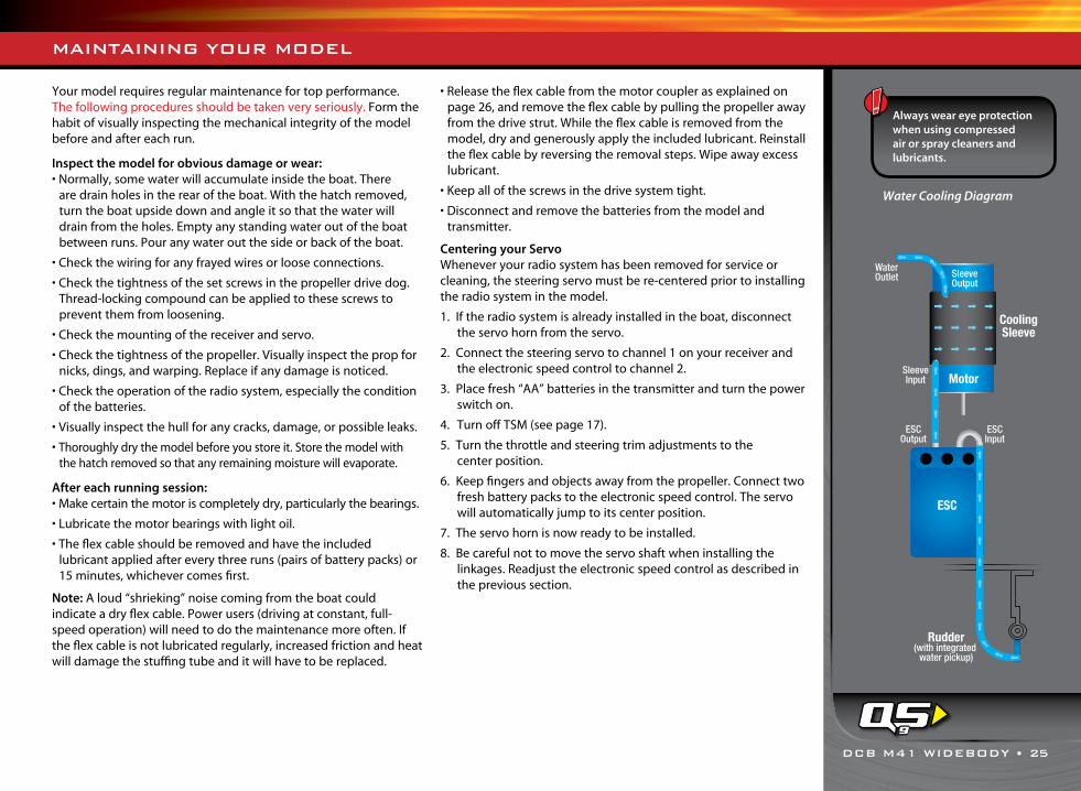
Inspect the model for obvious damage or wear:• Normally, some water will accumulate inside the boat. There
are drain holes in the rear of the boat. With the hatch removed, turn the boat upside down and angle it so that the water will drain from the holes. Empty any standing water out of the boat between runs. Pour any water out the side or back of the boat.
• Check the wiring for any frayed wires or loose connections.
• Check the tightness of the set screws in the propeller drive dog. Thread-locking compound can be applied to these screws to prevent them from loosening.
• Check the mounting of the receiver and servo.
• Check the tightness of the propeller. Visually inspect the prop for nicks, dings, and warping. Replace if any damage is noticed.
• Check the operation of the radio system, especially the condition of the batteries.
• Visually inspect the hull for any cracks, damage, or possible leaks.
• Thoroughly dry the model before you store it. Store the model with the hatch removed so that any remaining moisture will evaporate.
After each running session:• Make certain the motor is completely dry, particularly the bearings.
• Lubricate the motor bearings with light oil.
• The flex cable should be removed and have the included lubricant applied after every three runs (pairs of battery packs) or 15 minutes, whichever comes first.
Note: A loud “shrieking” noise coming from the boat could indicate a dry flex cable. Power users (driving at constant, full-speed operation) will need to do the maintenance more often. If the flex cable is not lubricated regularly, increased friction and heat will damage the stuffing tube and it will have to be replaced.
• Release the flex cable from the motor coupler as explained on page 26, and remove the flex cable by pulling the propeller away from the drive strut. While the flex cable is removed from the model, dry and generously apply the included lubricant. Reinstall the flex cable by reversing the removal steps. Wipe away excess lubricant.
• Keep all of the screws in the drive system tight.
• Disconnect and remove the batteries from the model and transmitter.
Centering your ServoWhenever your radio system has been removed for service or cleaning, the steering servo must be re-centered prior to installing the radio system in the model.
1. If the radio system is already installed in the boat, disconnect the servo horn from the servo.
2. Connect the steering servo to channel 1 on your receiver and the electronic speed control to channel 2.
3. Place fresh “AA” batteries in the transmitter and turn the power switch on.
4. Turn off TSM (see page 17).
5. Turn the throttle and steering trim adjustments to the center position.
6. Keep fingers and objects away from the propeller. Connect two fresh battery packs to the electronic speed control. The servo will automatically jump to its center position.
7. The servo horn is now ready to be installed.
8. Be careful not to move the servo shaft when installing the linkages. Readjust the electronic speed control as described in the previous section.
Always wear eye protection when using compressed air or spray cleaners and lubricants.
Water Cooling Diagram
9
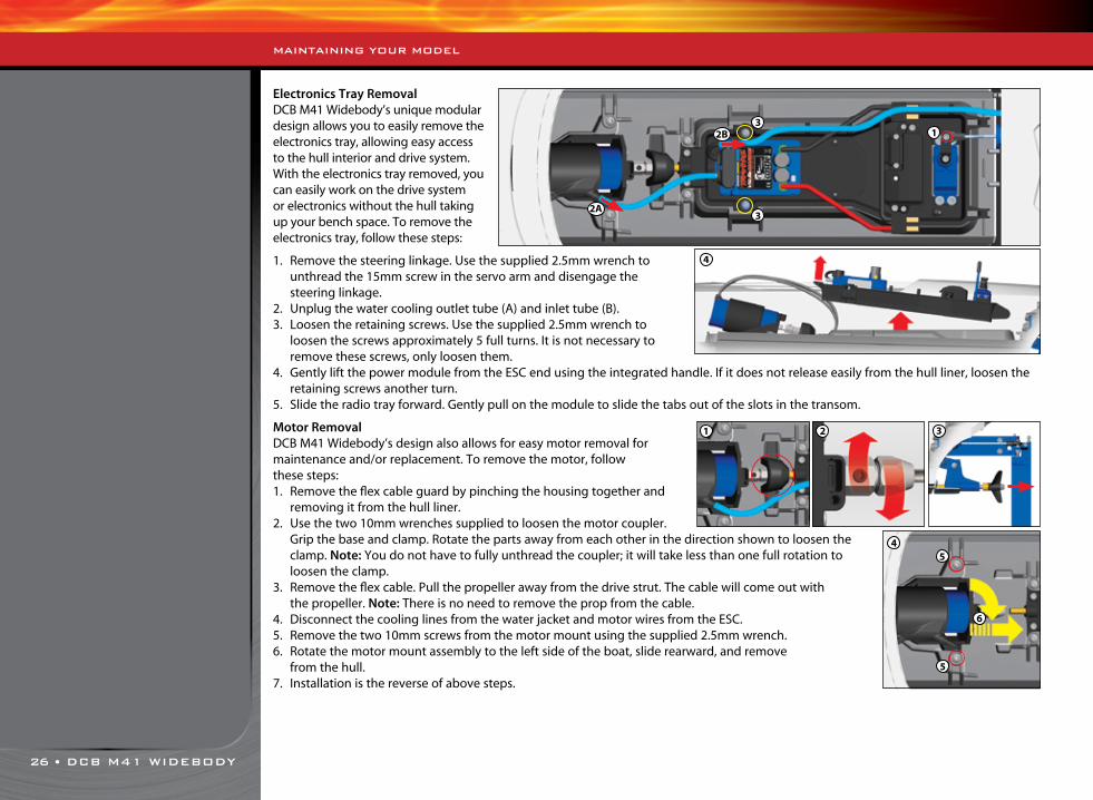
26 • DCB M41 WIDEBODY
Electronics Tray RemovalDCB M41 Widebody’s unique modular design allows you to easily remove the electronics tray, allowing easy access to the hull interior and drive system. With the electronics tray removed, you can easily work on the drive system or electronics without the hull taking up your bench space. To remove the electronics tray, follow these steps:
1. Remove the steering linkage. Use the supplied 2.5mm wrench to unthread the 15mm screw in the servo arm and disengage the steering linkage.
2. Unplug the water cooling outlet tube (A) and inlet tube (B).3. Loosen the retaining screws. Use the supplied 2.5mm wrench to
loosen the screws approximately 5 full turns. It is not necessary to remove these screws, only loosen them.
4. Gently lift the power module from the ESC end using the integrated handle. If it does not release easily from the hull liner, loosen the retaining screws another turn.
5. Slide the radio tray forward. Gently pull on the module to slide the tabs out of the slots in the transom.
Motor RemovalDCB M41 Widebody’s design also allows for easy motor removal for maintenance and/or replacement. To remove the motor, follow these steps:1. Remove the flex cable guard by pinching the housing together and
removing it from the hull liner.2. Use the two 10mm wrenches supplied to loosen the motor coupler.
Grip the base and clamp. Rotate the parts away from each other in the direction shown to loosen the clamp. Note: You do not have to fully unthread the coupler; it will take less than one full rotation to loosen the clamp.
3. Remove the flex cable. Pull the propeller away from the drive strut. The cable will come out with the propeller. Note: There is no need to remove the prop from the cable.
4. Disconnect the cooling lines from the water jacket and motor wires from the ESC. 5. Remove the two 10mm screws from the motor mount using the supplied 2.5mm wrench.6. Rotate the motor mount assembly to the left side of the boat, slide rearward, and remove
from the hull.7. Installation is the reverse of above steps.
1
2A
2B3
3
MAINTAINING YOUR MODEL
1 2 3
4
45
5
6

DCB M41 WIDEBODY • 27
TROUBLESHOOTING
The following section addresses some very basic questions you may have about your model. If you can’t find a solution here, you may call Traxxas Customer Service at 1-888-TRAXXAS (U.S. residents only).
If the model stopped suddenly:• Release the transmitter trigger immediately. Do not try and “force” the
model to move. Refer to the Boat Retrieval section on page 21 for recovery.
If there is an inconsistent reduction in power:• There could be something wound around the prop (such as trash, algae
or fishing line). If you continue to drive your model with a bound prop, the high load could create excessive heat and seriously damage the batteries, speed control, or motor. Refer to the Boat Retrieval section on page 21 for recovery.
• The model might have struck an object in the water causing driveline damage. Refer to the Boat Retrieval section on page 21 for recovery.
If there is an immediate reduction in power:• If the model’s power output is reduced suddenly, it is likely because the
Low-Voltage Detection system has switched on.
• Low-Voltage Detection will reduce power output to 25%. This allows sufficient power to return the model to shore. To prevent over-discharging your LiPo battery after Low-Voltage Detection limits power, return your model to shore and disconnect the LiPo pack(s) from the model immediately. Low-Voltage Detection allows operation with limited power for returning to shore ONLY. Operating the model longer than necessary to return to shore may cause over-discharging and permanent damage to LiPo batteries. Always return your model to shore and disconnect the batteries from your model as soon as Low-Voltage Detection limits power. The LED on the speed control will slowly blink red, indicating a low voltage shutdown. The VXL-6s will stay in the reduced power mode until a fully charged battery is connected.
• If you are not sure if the above condition occurred, do not operate the model. Refer to the Boat Retrieval section on page 21 for recovery.
INCREASING PERFORMANCEWhile your model is a great performer out of the box, there are steps you cantake to increase the speed of the boat.
1. Adjust the trim tab angle correctly. The trim tab angle should be trimmed down just enough to keep the bow of the boat from porpoising (bouncing up and down) in the current water conditions. If the trim tabs are set too low, then it pushes the bow lower and increases drag in the water (see page 22).
2. Maintain your boat. Your model will be faster if it is kept clean and in good working order. Replace the prop if it gets nicked or damaged. Keep the motor clean and oiled. Make sure the drivetrain turns freely with no binding or excess friction.
3. Use the best batteries and charger you can afford. Low-cost, low-capacity battery packs will limit the performance of your model. Likewise, a low-cost charger may not allow your batteries to achieve their peak power and capacity. For best performance, use battery packs rated for 5000mAh or higher. Traxxas Power Cell battery packs are specially constructed for durability and performance in high-power Traxxas models. Traxxas recommends the EZ-Peak Dual iD charger, part #2972, for quick charging. See Traxxas.com for more information.
Using Aftermarket Props DCB M41 Widebody’s included prop has been carefully designed for maximum performance and durability. It does not require sharpening or balancing and is inexpensive to replace if damaged. If you do wish to experiment with aftermarket props, Traxxas recommends using props that range in diameter from 38-42mm, with a pitch-to-diameter ratio of about 1.4:1. To determine this ratio, divide pitch by diameter. For example, the DCB M41 Widebody’s stock prop is 42mm in diameter with a pitch of 59mm (59 ÷ 42 = 1.404). Avoid props larger than 42mm, as these will increase amp draw and reduce performance.
Using Aftermarket Motors and Speed ControlsImportant: The VXL-6s Marine Speed Control and 540XL Brushless Motor have been optimized to work together for the absolute best performance, reliability, and efficiency. Using an aftermarket motor with the VXL-6s speed control, or an aftermarket speed control with the 540XL Brushless Motor, may result in damage to the Traxxas components and/or aftermarket components. Damage incurred by mixing Traxxas and aftermarket components will not be covered by any expressed or implied warranty. Only use the VXL-6s Marine speed control with the 540XL Brushless Motor.
If you wish to outfit your model with an aftermarket brushless system, you must replace both the motor and the speed control. Traxxas recommends a motor with a kV rating of 1600-1800 kV. Make certain the speed control you choose is compatible with your motor, is designed for marine use, and is waterproof. Water cooling is highly recommended. Additional silicone tubing may be required to properly plumb your speed control’s water-cooling system. The Traxxas water-cooling motor jacket is not compatible with all motors. Install an appropriate water-cooling system for the motor you choose. Traxxas is not responsible for damage to your model or the components you install in the model if you replace the power system with non-Traxxas components.
For the best performance, we highly recommend the DCB M41 Widebody’s factory-installed brushless system. It is optimized for the best performance, reliability, and ease of use in the DCB M41 Widebody, and fully supported by Traxxas customer service.
If you have questions or need technical assistance, call Traxxas at
1-888-TRAXXAS (1-888-872-9927) (U.S. residents only)
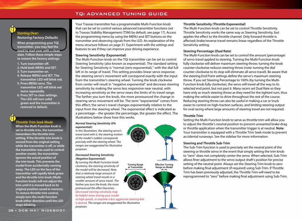
28 • DCB M41 WIDEBODY
Your Traxxas transmitter has a programmable Multi-Function knob that can be set to control various advanced transmitter functions (set to Traxxas Stability Management (TSM) by default, see page 17). Access the programming menu by using the MENU and SET buttons on the transmitter and observing signals from the LED. An explanation of the menu structure follows on page 31. Experiment with the settings and features to see if they can improve your driving experience.
Steering Sensitivity (Exponential)The Multi-Function knob on the TQi transmitter can be set to control Steering Sensitivity (also known as exponential). The standard setting for Steering Sensitivity is “normal (zero exponential),” with the dial full left in its range of travel. This setting provides linear servo response: the steering servo’s movement will correspond exactly with the input from the transmitter’s steering wheel. Turning the knob clockwise from center will result in “negative exponential” and decrease steering sensitivity by making the servo less responsive near neutral, with increasing sensitivity as the servo nears the limits of its travel range. The farther you turn the knob, the more pronounced the change in steering servo movement will be. The term “exponential” comes from this effect; the servo’s travel changes exponentially relative to the input from the steering wheel. The exponential effect is indicated as a percentage—the greater the percentage, the greater the effect. The illustrations below show how this works.
Normal Steering Sensitivity (0% exponential):In this illustration, the steering servo’s travel (and with it, the steering motion of the model’s rudder) corresponds precisely with the steering wheel. The ranges are exaggerated for illustrative purposes.
Decreased Steering Sensitivity (Negative Exponential):By turning the Multi-Function knob clockwise, the steering sensitivity of the model will be decreased. Note that a relatively large amount of steering wheel travel results in a smaller amount of servo travel. The farther you turn the knob, the more pronounced the effect becomes. Decreased steering sensitivity may be helpful when driving your model at high speeds, or anytime a less aggressive steering feel is desired. The ranges are exaggerated for illustrative purposes.
Throttle Sensitivity (Throttle Exponential)The Multi-Function knob can be set to control Throttle Sensitivity. Throttle Sensitivity works the same way as Steering Sensitivity, but applies the effect to the throttle channel. Only forward throttle is affected; brake/reverse travel remains linear regardless of the Throttle Sensitivity setting.
Steering Percentage (Dual Rate)The Multi-Function knob can be set to control the amount (percentage) of servo travel applied to steering. Turning the Multi-Function knob fully clockwise will deliver maximum steering throw; turning the knob counter-clockwise reduces steering throw (note: turning the dial counter-clockwise to its stop will eliminate all servo travel). Be aware that the steering End Point settings define the servo’s maximum steering throw. If you set Steering Percentage to 100% (by turning the Multi-Function knob fully clockwise), the servo will travel all the way to its selected end point, but not past it. Many racers set Dual Rate so they have only as much steering throw as they need for the tightest turn, thus making the vehicle easier to drive throughout the rest of the course. Reducing steering throw can also be useful in making a car or truck easier to control on high-traction surfaces, and limiting steering output for oval racing where large amounts of steering travel are not required.
Throttle TrimSetting the Multi-Function knob to serve as throttle trim will allow you to adjust the throttle’s neutral position to prevent unwanted brake drag or throttle application when the transmitter trigger is at neutral. Note: Your transmitter is equipped with a Throttle Trim Seek mode to prevent accidental runaways. See the sidebar for more information.
Steering and Throttle Sub-TrimThe Sub-Trim function is used to precisely set the neutral point of the steering or throttle servo in the event that simply setting the trim knob to “zero” does not completely center the servo. When selected, Sub-Trim allows finer adjustment to the servo output shaft’s position for precise setting of the neutral point. Always set the Steering Trim knob to zero before making final adjustment (if required) using Sub-Trim. If Throttle Trim has been previously adjusted, the Throttle Trim will need to be reprogrammed to “zero” before making final adjustment using Sub-Trim.
TQi ADVANCED TUNING GUIDE
Starting Over: Restoring Factory Defaults
When programming your TQi transmitter, you may feel the need to start over with a clean slate. Follow these simple steps to restore the factory settings:
1. Turn transmitter off.2. Hold both MENU and SET.3. Turn transmitter on.4. Release MENU and SET. The
transmitter LED will blink red.5. Press MENU once. The
transmitter LED will blink red twice repeatedly.
6. Press SET to clear settings. The LED will turn solid green and the transmitter is restored to default.
Throttle Trim Seek ModeWhen the Multi-Function knob is set to throttle trim, the transmitter remembers the throttle trim setting. If the throttle trim knob is moved from the original setting while the transmitter is off, or while the transmitter was used to control another model, the transmitter ignores the actual position of the trim knob. This prevents the model from accidentally running away. The LED on the face of the transmitter will rapidly blink green and the throttle trim knob (Multi-Function knob) will not adjust the trim until it is moved back to its original position saved in memory. To restore throttle trim control, simply turn the multi-function knob either direction until the LED stops blinking.
Turning Range at Transmitter
Effective Turning Range on Model

DCB M41 WIDEBODY • 29
TQi ADVANCED TUNING GUIDE
Steering and Throttle End PointsThe TQi transmitter allows you to choose the limit of the servo’s travel range (or its “end point”) independently for left and right travel (on the steering channel) and throttle/brake travel (on the throttle channel). This allows you to fine-tune the servo settings to prevent binding caused by the servo moving steering or throttle linkages (in the case of a nitro vehicle) farther than their mechanical limits. The end point adjustment settings you select will represent what you wish to be the servo’s maximum travel; the Steering Percentage or Braking Percentage functions will not override the End Point settings.
Setting LockOnce you’ve adjusted all of these settings the way you like them, you may want to disable the Multi-Function knob so none of your settings can be changed. This is especially handy if you operate multiple vehicles with a single transmitter via Traxxas Link™ Model Memory.
Multiple Settings and the Multi-Function KnobIt is important to note that settings made with the Multi-Function knob are “overlaid” on top of each other. For example, if you assign the Multi-Function to adjust Steering Percentage and set it for 50%, then reassign the knob to control Steering Sensitivity, the transmitter will “remember” the Steering Percentage setting. Adjustments you make to Steering Sensitivity will be applied to the 50% steering throw setting you selected previously. Likewise, setting the Multi-Function knob to “disabled” will prevent the knob from making further adjustments, but the last setting of the Multi-Function knob will still apply.
Braking PercentageR/C boats do not have brakes, as the natural resistance of the water will slow and stop the boat when the throttle is shut off; however, if you use your TQi transmitter with a car or truck, you may find the Braking Percentage function useful. When set for Braking Percentage, the Multi-Function knob will control the amount of brake travel applied by the throttle/brake servo in a nitro-powered model. Electric models do not have a servo-operated brake but the Braking Percentage function still operates the same way in electric models. Turning the Multi-Function knob full clockwise will deliver maximum brake throw; turning the knob counter-clockwise reduces brake throw. Note: Turning the dial counter-clockwise to its stop will eliminate all brake action.
FailsafeYour Traxxas radio system is equipped with a built-in failsafe function that returns the throttle to its last saved neutral position in the event of a signal loss. The LED on the transmitter and the receiver will rapidly flash red.
LED Color / Pattern Name Notes
Solid green Normal Driving Mode See page 15 for information on how to use your transmitter controls.
Slow red (0.5 sec on / 0.5 sec off) Binding See page 16 for more information on binding.
Flashing fast green (0.1 sec on / 0.15 sec off) Throttle Trim Seek ModeTurn the Multi-Function knob right or left until the LED stops flashing. See page 28 for more information.
Flashing medium red (0.25 sec on / 0.25 sec off) Low Battery Alarm Put new batteries in the transmitter. See page 13 for more information.
Flashing fast red (0.125 sec on / 0.125 sec off) Link Failure / ErrorTransmitter and receiver are no longer bound. Turn the system off and then back on to resume normal operation. Find source of the link failure (ie out of range, low batteries, damaged antenna).
Programming Patterns
Counts out number (green or red) then pauses Current menu position See Menu Tree for more information.
Fast green 8 times Menu setting accepted (on SET)
Fast red 8 times Menu SET invalid User error such as trying to delete a locked model.
LED Color / Pattern Name Notes
Solid green Normal Driving Mode See page 15 for information on how to use your transmitter controls.
Flashing slow red Binding See page 16 for more information on binding.
Flashing medium red Fail-Safe / Low-Voltage DetectConsistent Low-Voltage in the receiver triggers Fail-Safe so there is enough power to center the throttle servo before it completely loses power.
x8
x8
or
TRANSMITTER LED CODES
RECEIVER LED CODES
30 • DCB M41 WIDEBODY
TQi ADVANCED TUNING GUIDE
TRAXXAS LINK MODEL MEMORYTraxxas Link Model Memory is an exclusive, patent-pending feature of the TQi transmitter. Each time the transmitter is bound to a new receiver, it saves that receiver in its memory along with all the settings assigned to that receiver. When the transmitter and any bound receiver are switched on, the transmitter automatically recalls the settings for that receiver. There is no need to manually select your vehicle from a list of model memory entries.
Model LockThe Traxxas Link Model Memory feature can store up to thirty models (receivers) in its memory. If you bind a thirty-first receiver, Traxxas Link Model Memory will delete the “oldest” receiver from its memory (in other words, the model you used the longest time ago will be deleted). Activating Model Lock will lock the receiver in memory so it cannot be deleted.
You may also bind multiple TQi transmitters to the same model making it possible to pick up any transmitter and any previously bound model in your collection and simply turn them on and drive. With Traxxas Link Model Memory, there is no need remember which transmitter goes with which model and there is never a need to have to select any model from a list of model memory entries. The transmitter and receiver do it all for you automatically.
To activate Model Lock:1. Switch on the transmitter and receiver you wish to lock. 2. Press and hold MENU. Release when the status LED blinks green.3. Press MENU three times. The status LED will blink green four
times repeatedly.4. Press SET. The status LED will blink green in single-flash intervals. 5. Press SET once. The status LED will blink red once repeatedly. 6. Press MENU once, the LED will blink red twice repeatedly. 7. Press SET, the LED will blink rapidly green. The memory is now
locked. Press and hold MENU to return to driving mode. Note: To unlock a memory, press SET twice at step 5. The LED will
blink rapidly green to indicate the model is unlocked. To unlock all models, press MENU twice at step 6 and then press SET.
To delete a model:At some point, you may wish to delete a model you no-longer drive from the memory.1. Switch on the transmitter and receiver you wish to delete. 2. Press and hold MENU. Release when the status LED blinks green.3. Press MENU three times. The status LED will blink green four
times repeatedly.4. Press SET once. The status LED will blink green once repeatedly. 5. Press MENU once. The status LED will blink green twice repeatedly. 6. Press SET. The memory is now selected to be deleted. Press SET to
delete the model. Press and hold MENU to return to driving mode.

TQi ADVANCED TUNING GUIDE
Press MENU to move through options. Press SET to select an option.
Press MENU to move through options. Press SET to select an option.
Press SET to select an option.
Enter ProgrammingPress and hold MENU for 3 seconds
Steering Sensitivity (Expo)One Blink Red
1
ElectricOne Blink Red
1
UnlockOne Blink Red
1
Servo ReversingOne Blink Red
1
Servo ReversingOne Blink Red
1
Confirm DeletionOne Blink Red
1
Multi-Function KnobOne Blink Green
1
Channel SetupTwo Blinks Green
2
Mode SelectionThree Blinks Green
3
Traxxas-LinkFour Blinks Green
4
Steering (Channel 1)One Blink Green
1
Model LockingOne Blink Green
1
Throttle (Channel 2)Two Blinks Green
2
Delete ModelTwo Blinks Green
2
Throttle Sensitivity (Expo)Two Blinks Red
2
NitroTwo Blinks Red
2
LockTwo Blinks Red
2
Sub-TrimTwo Blinks Red
2
Sub-TrimTwo Blinks Red
2
Steering % (Dual-Rate)Three Blinks Red
3
Unlock AllThree Blinks Red
3
End PointsThree Blinks Red
3
Braking % Four Blinks Red
4
Reset End PointsFour Blinks Red
4
Throttle TrimFive Blinks Red
5
Knob DisabledSix Blinks Red
6
Press MENU
Press MENU
Press MENU
Press SET
Press SET
Press SET
Press SET
Press SET
Press SET
Press SET
Press SET to reverse servo direction.
Press SET to reverse servo direction.
Press SET to restore factory default end points.
Reset End PointsFour Blinks Red
4 Press SET to restore factory default end points.
Use knob to adjust sub-trim. Press SET to save.
Use knob to adjust sub-trim. Press SET to save.
Use steering wheel to adjust. Turn right to desired end point, press set to save.
Turn left to desired end point and press set to save. To reset max throw: Let go of controls and press SET.
Note: The transmitter is “live” during programming so you can test the settings real time without having to exit the Menu Tree.
End PointsThree Blinks Red
3 Use trigger to adjust. Pull back to desired end point, press set to save. Push
forward to desired end point and press set to save. To reset max throw: Let go of controls and press SET.
The Menu Tree below shows how to navigate through the TQi transmitter’s various settings and functions. Press and hold MENU to enter the Menu Tree, and use the following commands to navigate through the menu and select options.
MENU: When you enter a menu, you always start at the top. Press MENU to move down the Menu Tree. When you reach the bottom of the tree, pressing MENU again will return you to the top.
SET: Press SET to move across the Menu Tree and select options. When an option is committed to the transmitter’s memory, the status LED will rapidly blink green.
BACK: Press both MENU and SET to go back one level in the Menu Tree.
EXIT: Press and hold MENU to exit programming. Your selected options will be saved.
ECHO: Press and hold SET to activate the “echo” function. Echo will “play back” your current position on the Menu Tree should you lose your place. For example: If your current position is Steering Channel End Points, holding SET will cause the LED to blink green twice, green once, and then red three times. Echo will not alter your adjustments or change your position in the programming sequence.
MENU TREE
Below is an example of how to access a function in the Menu Tree. In the example, the user is setting the Multi-Function knob to be a Steering % (Dual-Rate) control.
To set the Multi-Function knob to control STEERING % (DUAL-RATE):1. Switch the transmitter on.2. Press and hold MENU until the green LED lights. It will blink in single
intervals.3. Press SET. The red LED will blink in single intervals to indicate Steering
Sensitivity (Expo) has been selected.4. Press MENU twice. The red LED will blink three times repeatedly to
indicate Steering % (Dual-Rate) has been selected.5. Press SET to select. The green LED will blink 8 times fast to indicate
successful selection.6. Press and hold MENU to return to driving mode.
Restoring Factory Defaults:
Transmitter OFF
Hold both MENU and SET
Transmitter ON
Release MENU and SET red LED blinks
Press SET to clear settings. LED will turn solid green. Transmitter is restored to default
Press SET
Torque Control*Seven Blinks Red
7
TSMEight Blinks Red
8
Press MENU
Press MENU
*Torque Control is a feature designed only for use with the power system in the Traxxas Funny Car Race Replica (Model #6907).
Press MENU
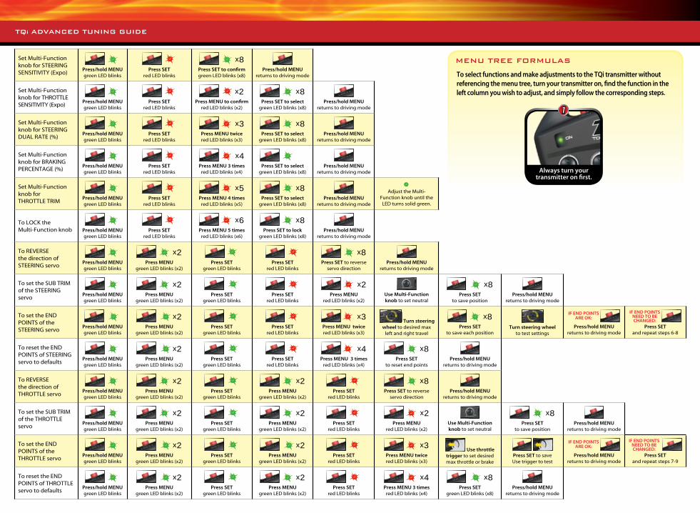
TQi ADVANCED TUNING GUIDE
Set Multi-Function knob for STEERING SENSITIVITY (Expo)
Press/hold MENU green LED blinks
Press SET
red LED blinks
x8
Press SET to confirm green LED blinks (x8)
Press/hold MENU
returns to driving mode
Set Multi-Function knob for THROTTLE SENSITIVITY (Expo)
Press/hold MENU green LED blinks
Press SET
red LED blinks
x2
Press MENU to confirm red LED blinks (x2)
x8
Press SET to select green LED blinks (x8)
Press/hold MENU returns to driving mode
Set Multi-Function knob for STEERING DUAL RATE (%)
Press/hold MENU green LED blinks
Press SET
red LED blinks
x3
Press MENU twice red LED blinks (x3)
x8
Press SET to select green LED blinks (x8)
Press/hold MENU returns to driving mode
Set Multi-Function knob for BRAKING PERCENTAGE (%)
Press/hold MENU green LED blinks
Press SET
red LED blinks
x4
Press MENU 3 times red LED blinks (x4)
Press SET to select
green LED blinks (x8)Press/hold MENU
returns to driving mode
Set Multi-Function knob for THROTTLE TRIM
Press/hold MENU green LED blinks
Press SET
red LED blinks
x5
Press MENU 4 times red LED blinks (x5)
x8
Press SET to select green LED blinks (x8)
Press/hold MENU returns to driving mode
Adjust the Multi-Function knob until the LED turns solid green.
To LOCK the Multi-Function knob
Press/hold MENU green LED blinks
Press SET
red LED blinks
x6
Press MENU 5 times red LED blinks (x6)
x8
Press SET to lock green LED blinks (x8)
Press/hold MENU returns to driving mode
To REVERSE the direction of STEERING servo
Press/hold MENU green LED blinks
x2
Press MENUgreen LED blinks (x2)
Press SET green LED blinks
Press SET
red LED blinks
x8
Press SET to reverse servo direction
Press/hold MENU returns to driving mode
To set the SUB TRIM of the STEERING servo
Press/hold MENU green LED blinks
x2
Press MENUgreen LED blinks (x2)
Press SET
green LED blinks
Press SET
red LED blinks
x2
Press MENU red LED blinks (x2)
Use Multi-Function knob to set neutral
x8
Press SET to save position
Press/hold MENU returns to driving mode
To set the END POINTS of the STEERING servo
Press/hold MENU green LED blinks
x2
Press MENU green LED blinks (x2)
Press SET
green LED blinks
Press SET
red LED blinks
x3
Press MENU twicered LED blinks (x3)
Turn steering wheel to desired max
left and right travel
x8
Press SET to save each position
Turn steering wheel to test settings
IF END POINTS ARE OK:
Press/hold MENU returns to driving mode
IF END POINTS NEED TO BE CHANGED:
Press SET and repeat steps 6-8
To reset the END POINTS of STEERING servo to defaults
Press/hold MENU green LED blinks
x2
Press MENU green LED blinks (x2)
Press SET
green LED blinks
Press SET
red LED blinks
x4
Press MENU 3 timesred LED blinks (x4)
x8
Press SET to reset end points
Press/hold MENU returns to driving mode
To REVERSE the direction of THROTTLE servo
Press/hold MENU green LED blinks
x2
Press MENUgreen LED blinks (x2)
Press SET
green LED blinks
x2
Press MENUgreen LED blinks (x2)
Press SET
red LED blinks
x8
Press SET to reverse servo direction
Press/hold MENU returns to driving mode
To set the SUB TRIM of the THROTTLE servo
Press/hold MENU green LED blinks
x2
Press MENUgreen LED blinks (x2)
Press SET
green LED blinks
x2
Press MENUgreen LED blinks (x2)
Press SET
red LED blinks
x2
Press MENU red LED blinks (x2)
Use Multi-Function knob to set neutral
x8
Press SET to save position
Press/hold MENU returns to driving mode
To set the END POINTS of the THROTTLE servo
Press/hold MENU green LED blinks
x2
Press MENU green LED blinks (x2)
Press SET
green LED blinks
x2
Press MENU green LED blinks (x2)
Press SET
red LED blinks
x3
Press MENU twice red LED blinks (x3)
Use throttle trigger to set desired max throttle or brake
Press SET to saveUse trigger to test
IF END POINTS ARE OK:
Press/hold MENU returns to driving mode
IF END POINTS NEED TO BE CHANGED:
Press SET and repeat steps 7-9
To reset the END POINTS of THROTTLE servo to defaults
Press/hold MENU green LED blinks
x2
Press MENU green LED blinks (x2)
Press SET
green LED blinks
x2
Press MENUgreen LED blinks (x2)
Press SET
red LED blinks
x4
Press MENU 3 times red LED blinks (x4)
x8
Press SET green LED blinks (x8)
Press/hold MENU returns to driving mode
MENU TREE FORMULAS
To select functions and make adjustments to the TQi transmitter without referencing the menu tree, turn your transmitter on, find the function in the left column you wish to adjust, and simply follow the corresponding steps.
Always turn yourtransmitter on first.
1
TRAXXAS • 33
TQi ADVANCED TUNING GUIDE
PROGRAMMING YOUR TQi TRANSMITTER WITH YOUR APPLE iPHONE, iPAD, iPOD TOUCH, OR ANDROID MOBILE DEVICEThe Traxxas Link™ Wireless Module (part #6511, sold separately) for the TQi transmitter installs in minutes to transform your Apple® iPhone®, iPad®, iPod touch®, or Android™ device into a powerful tuning tool that allows you to replace the transmitter’s button/LED programming system with an intuitive, high-definition, full-color graphical user interface.
Traxxas LinkThe powerful Traxxas Link app (available in the Apple App Store℠ or on Google Play™) gives you complete control over the operation and tuning of your Traxxas model with stunning visuals and absolute precision. Install Traxxas Link telemetry sensors on the model, and Traxxas Link displays real-time data such as speed, RPM, temperature, and battery voltage.
Intuitive iPhone, iPad, iPod touch, and Android interfaceTraxxas Link makes it easy to learn, understand, and access powerful tuning options. Control Drive Effects settings such as TSM assistance percentage; steering and throttle sensitivity; steering percentage; braking strength; and throttle trim by simply touching and dragging the sliders on the screen.
Real-Time TelemetryWhen you equip your model with sensors, the Traxxas Link dashboard comes to life showing you speed, battery voltage, RPM, and temperature. Set threshold warnings and log maximums, minimums, or averages. Use the recording function to document your dashboard view, with sound, so that you can keep your eyes on your driving and not miss a single apex.
Manage up to 30 Models with Traxxas LinkThe TQi radio system automatically keeps track of what vehicles it has bound to and what settings were used for each--up to 30 models total! Traxxas Link provides a visual interface to name the models, customize their settings, attach profiles, and lock them into memory. Simply choose a model and any previously bound transmitter, power them up, and start having fun.
Apple, the Apple logo, iPhone, iPad, and iPod touch are trademarks of Apple Inc., registered in the U.S. and other countries. App Store is a service mark of Apple Inc. Android and Google Play are trademarks of Google Inc.
Tap and slide to adjust TSM, Steering Sensitivity, Throttle Trim, Braking Percent, and more!
The customizable Traxxas Link dashboard delivers real-time rpm, speed, temperature, and voltage data.
Traxxas Link Model Memory simplifies organizing your collection of vehicles.
Compatible with:iPod touch (5th generation and later)iPad (3rd generation and later)iPad miniAndroid 4.4 (and later)
iPhone 4SiPhone 5iPhone 5CiPhone 5S
The Traxxas Link Wireless Module is sold separately (part #6511). The Traxxas Link application is available from the Apple App store for iPhone, iPad, or iPod touch and on Google Play for Android devices. iPhone, iPad, iPod touch, or the Android device are not included with the Traxxas Link Wireless Module.
For more information about the Traxxas Link Wireless Module and the Traxxas Link application, visit Traxxas.com.

160525 57046-4-OM-EN-R00
6250 TRAXXAS WAY, McKINNEY, TEXAS 750701-888-TRAXXAS
owner’s manual
MODEL 57046-4


