e-ISSN: 2456-3463 International Journal of Innovations in Engineering and Science, Vol. 2, No.1, 2017 www.ijies.net Design of Loop Wheel Suspension System Prof. M.C. Shinde 1 , Assistant Professor Shevale Hanumant 1 , Priyankal Vishwakarma 2 , Kunal Rangwani 3 , Sushant Shinde 4 , UG Student , Department of Mechanical Engineering (VIT Campus) Suman Ramesh Tulsiani Technical Campus-Faculty of Engineering, Khamshet, Pune, India, 410405 Abstract –Recently, there is an increasing interest on bicycle riding for recreation or fitness purpose. Bicycles are also accepted as urban transportation due to the consciousness of environmental protection. For a more comfortable riding experience, many bicycles are equipped with a suspension system. The aim is to design, analyze and fabricate a wheel of a cycle with tangential suspension system in the wheel itself. It is done so by introducing spring like material. Thus, the spokes of the cycle are replaced by leaf spring of variable length which can be varied according to the given conditions. The leaf springs are attached to the hub which can dislocate from its center and hence can be termed as “Floating hub”. The leaf springs are attached to the rim at the other end where the length of the spring can be adjusted. For serving the purpose a 26T cycle is taken under consideration where the suspension system is introduced in its front wheel by making the required replacements. Though this system is currently applicable only in bicycles, it has a wide future scope. Also, the springs can be replaced with damper. However, introduction of this suspension system in the bicycle itself provides more comfort to the rider than a regular bicycle. Keywords-Design, FEA and fabrication of a wheel with tangential suspension for a two-wheeler vehicle. INTRODUCTION Although the origin of the wheel may be obscure, its invention as a load carrying device marked the advent of machinery. Today the wheel is an essential part of most machines in the form of gears, pulleys, cams, sprockets, bearings, and other rotating devices. However, it is still most conspicuous as a load carrier; and, from a technical perspective, the bicycle wheel stands out as one of the most elegant of these. The wire-spoked bicycle wheel was introduced more than a century ago to replace wooden wheels with thick, rigid spokes. Tensioning the wires made these wheels possible, and with them came the lightweight bicycle that we know today. Wire spokes not only reduced weight but also improved durability. Today's wire wheels can carry more than a hundred times their own weight. In off-road bicycling, skilled riders often jump from high obstacles, subjecting their wheels to forces of more than a quarter ton. Although the bicycle is the world's most common vehicle, few people understand how its wheels achieve their unusual strength. 1
Transcript
e-ISSN: 2456-3463International Journal of Innovations in Engineering and Science, Vol. 2, No.1, 2017
www.ijies.net
Design of Loop Wheel Suspension SystemProf. M.C. Shinde1, Assistant Professor
, Department of Mechanical Engineering(VIT Campus) Suman Ramesh Tulsiani Technical Campus-Faculty of Engineering, Khamshet, Pune, India, 410405
Abstract –Recently, there is an increasing interest on bicycle riding for recreation or fitness purpose. Bicycles are also accepted as urban transportation due to the consciousness of environmental protection. For a more comfortable riding experience, many bicycles are equipped with a suspension system. The aim is to design, analyze and fabricate a wheel of a cycle with tangential suspension system in the wheel itself. It is done so by introducing spring like material. Thus, the spokes of the cycle are replaced by leaf spring of variable length which can be varied according to the given conditions. The leaf springs are attached to the hub which can dislocate from its center and hence can be termed as “Floating hub”. The leaf springs are attached to the rim at the other end where the length of the spring can be adjusted. For serving the purpose a 26T cycle is taken under consideration where the suspension system is introduced in its front wheel by making the required replacements. Though this system is currently applicable only in bicycles, it has a wide future scope. Also, the springs can be replaced with damper. However, introduction of this suspension system in the bicycle itself provides more comfort to the rider than a regular bicycle.
Keywords-Design, FEA and fabrication of a wheel with tangential suspension for a two-wheeler vehicle.
INTRODUCTIONAlthough the origin of the wheel may be obscure, its invention as a load carrying device marked the advent of machinery. Today the wheel is an essential part of most machines in the form of gears, pulleys, cams, sprockets, bearings, and other rotating devices. However, it is still most conspicuous as a load carrier; and, from a technical perspective, the bicycle wheel stands out as one of the most elegant of these. The wire-spoked bicycle wheel was introduced more than a century ago to replace wooden wheels with thick, rigid spokes. Tensioning the wires made these wheels possible, and with them came the lightweight bicycle that we know today. Wire spokes not only reduced weight but also improved durability. Today's wire wheels can carry more than a hundred
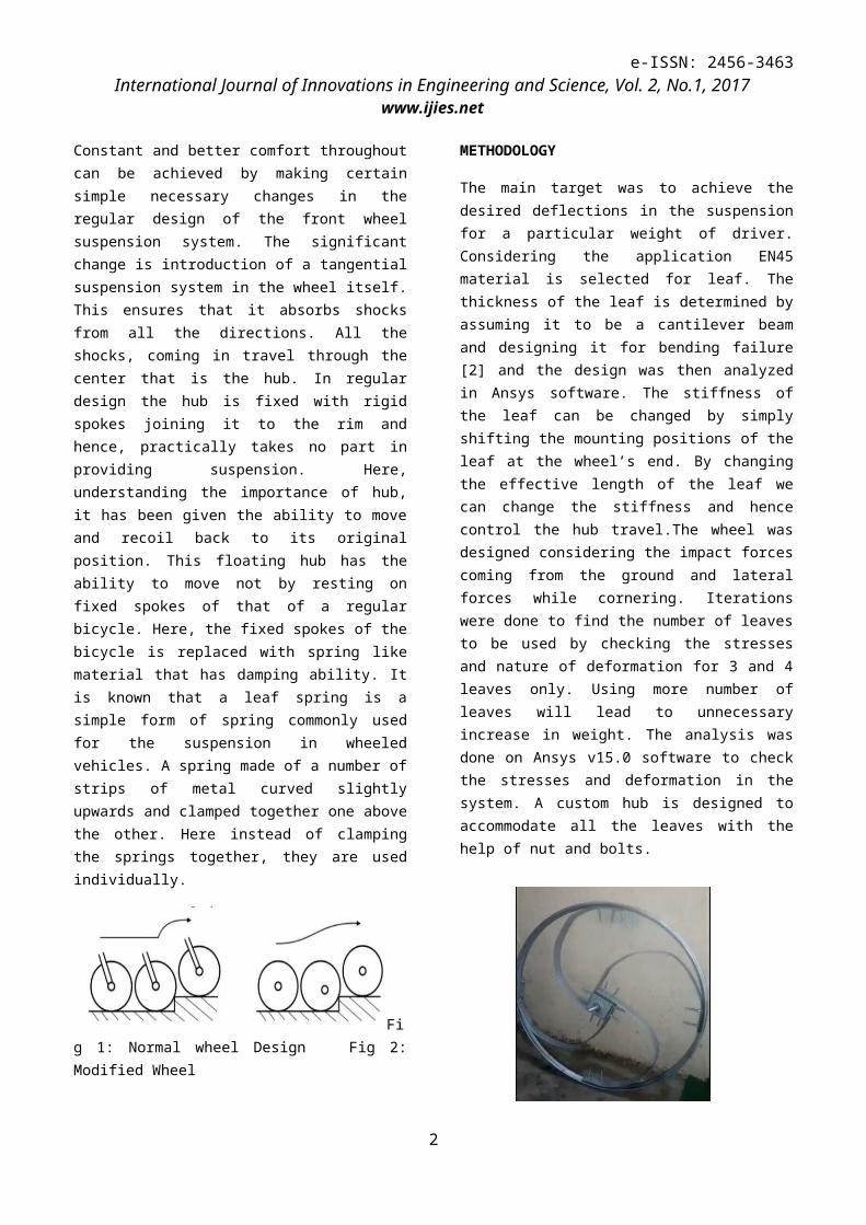
times their own weight. In off-road bicycling, skilled riders often jump from high obstacles, subjecting their wheels to forces of more than a quarter ton. Although the bicycle is the world's most common vehicle, few people understand how its wheels achieve their unusual strength. Constant and better comfort throughout can be achieved by making certain simple necessary changes in the regular design of the front wheel suspension system. The significant change is introduction of a tangential suspension system in the wheel itself. This ensures that it absorbs shocks from all the directions. All the shocks, coming in travel through the center that is the hub. In regular design the hub is fixed with rigid spokes joining it to the rim and hence, practically takes no part in providing suspension. Here, understanding the importance of hub, it has been given the ability to move and recoil back to its original position. This floating hub has the ability to move not by resting on fixed spokes of that of a regular bicycle. Here, the fixed spokes of the bicycle is replaced with spring like material that has damping ability. It is known that a leaf spring is a simple form of spring commonly used for the suspension in wheeled vehicles. A spring made of a number of strips of metal curved slightly upwards and clamped together one above the other. Here instead of clamping the springs together, they are used individually.
Fig 1: Normal wheel Design Fig 2: Modified Wheel
METHODOLOGY
The main target was to achieve the desired deflections in the suspension for a particular weight of driver. Considering the application EN45 material is selected for leaf. The thickness of the leaf is determined by
1
e-ISSN: 2456-3463International Journal of Innovations in Engineering and Science, Vol. 2, No.1, 2017
www.ijies.net
assuming it to be a cantilever beam and designing it for bending failure [2] and the design was then analyzed in Ansys software. The stiffness of the leaf can be changed by simply shifting the mounting positions of the leaf at the wheel’s end. By changing the effective length of the leaf we can change the stiffness and hence control the hub travel.The wheel was designed considering the impact forces coming from the ground and lateral forces while cornering. Iterations were done to find the number of leaves to be used by checking the stresses and nature of deformation for 3 and 4 leaves only. Using more number of leaves will lead to unnecessary increase in weight. The analysis was done on Ansys v15.0 software to check the stresses and deformation in the system. A custom hub is designed to accommodate all the leaves with the help of nut and bolts.
Fig. 3- fig shows the matter
DESIGN
Dimension of cross section of the leaf is to be determined. The width of the leaf material was kept as 35mm as it cannot be more than the width of the wheel.
Considering front impact case, using impulse momentum theorem,
F*t = m*v
Time of impact, t=0.5 sec
Mass of cycle including rider, m= 100 kg
Max. velocity, v=30kmph= 8.3 m/s
F= 1660 N
For determining the thickness of the Leaf, let us consider it as a cantilevered beam.
Bending Stress is given by,
Sb=1.5 WLb t2
Sb= 400 MPa
W= 1660 N
L= 350mm
B= 35mm
From above equation, we get thickness of leaf, t=2.913 ~ 3mm.
Procedure for ANSYS AnalysisStatic analysis is used to determine the displacements stresses, stains and forces instructures or components due to loads that act on the component. Steady loading inresponse conditions are assumed. The kinds of loading that can be applied in a staticanalysis include externally applied forces and pressures, steady state inertial forcessuch as gravity or rotational velocity imposed (non-zero) displacements, temperatures(for thermal strain). A static analysis can be either linear or non linear. work we consider linear static analysis.The procedure for static analysis consists of these main steps:
1. Building the model2. Obtaining the solution3. Reviewing the results.Material properties of Different materials:
e-ISSN: 2456-3463International Journal of Innovations in Engineering and Science, Vol. 2, No.1, 2017
www.ijies.net
6. Analysis of Leaf
The Leaf was designed in Catia V5R20. The material used for Leaf is EN45 as it possess the properties like high elasticity and higher fatigue strength.
Fig.4: CAD model of Leaf
Static structural analysis is done to find the safety of the leaf under impact.For analysis of leaf it was assumed as a cantilever, the end which is attached to hub was constrained and the force due to impact was applied on the other end
7. Analysis of hubA custom hub is designed to accommodate the leaf springs. Material used for hub is EN8 as it has the properties of high strength and hardness. Structural analysis[5] is done, taking into consideration the forces acting on the hub.
Fig.5: CAD model HUB
Table 2: Results of analysis of HubObject Name
Total Deformation Equivalent Stress
Minimum 0. mm 0.13633 MPa
Maximum 7.3358e-003 mm 25.42 MPa
5.9 RESULTSAfter the problem is solved we get detail results about equivalent stress, deformation, strain, FOS etc. in the form of pictorial representation and animation. From the
given data we can analyze whether the design is safe or not by comparing the stress induced and the yield strength of the material (for ductile material) and ultimate strength (for brittle material). We can also improve the design by doing necessary changes in design to reduce the stress concentration and better stress distribution. From these results we can also study the behavior of material and design under different loading conditions.
8.1 Impact Force Analysis
Steady state structural analysis is performed to check the safety of the design. Using impulse momentum principle, force was calculated when the cycle hits a rigid wall with a velocity of 30kmph. The force obtained was 1660 N.
Fig. 6: Stress distribution in impact forces for 3 leaf
Table 3: Result of analysis of 3 leaf wheel for front impact
Object Name Total Deformation Equivalent Stress
Minimum 0. mm 0.11642 MPa
Maximum 12.1 676.44 MPa
Table 4: Stress distribution in impact forces for 4 leafObject Name
Total Deformation Equivalent Stress
Minimum 0. mm 0.11642 MPa
Maximum 9.45 mm 535.3 MPa
3
e-ISSN: 2456-3463International Journal of Innovations in Engineering and Science, Vol. 2, No.1, 2017
www.ijies.net
Fig. 7: Stress distribution in impact forces for 5 leaf
Table 5: Result of analysis of 5 leaf wheel for front impact
Object Name Total Deformation Equivalent Stress
Minimum 0 mm 4.7523e-011 MPa
Maximum 4.78 mm 510.88Pa
Lateral Force Analysis
It is important to check the safety of design in cornering conditions, the system must remain stable while taking any sharp turn. The wheel is constrained and lateral force[3] was applied at the centre of the hub in the lateral direction.
Force was calculated for condition where cycle takes a turn of radius 2m at a velocity of 30kmph. 1400 N force was applied at the center of the hub in the lateral direction. The main consideration was to have least deflection in the lateral direction which will determine the stability of the system while cornering.
Fig.8: Stress distribution in lateral forces for 3 leaf
Table 6: Result of analysis of 3 leaf wheel for lateral forces
Object Name
Total Deformation Equivalent Stress
Minimum 0. mm 8.1233e-009 MPa
Maximum 2.5813 mm 611.51 MPa
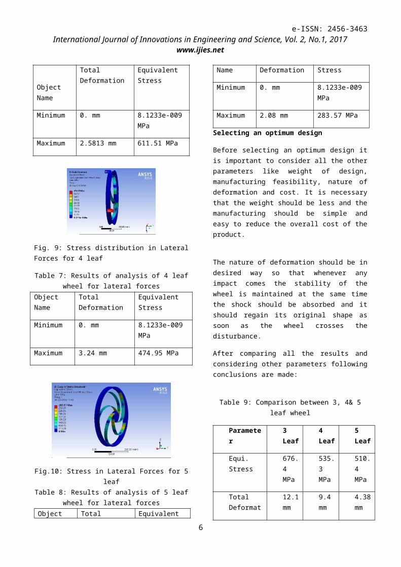
Fig. 9: Stress distribution in Lateral Forces for 4 leaf
Table 7: Results of analysis of 4 leaf wheel for lateral forces
Object Name Total Deformation Equivalent Stress
Minimum 0. mm 8.1233e-009 MPa
Maximum 3.24 mm 474.95 MPa
Fig.10: Stress in Lateral Forces for 5 leafTable 8: Results of analysis of 5 leaf wheel for lateral
forcesObject Name Total Deformation Equivalent Stress
Minimum 0. mm 8.1233e-009 MPa
Maximum 2.08 mm 283.57 MPa
Selecting an optimum design
Before selecting an optimum design it is important to consider all the other parameters like weight of design, manufacturing feasibility, nature of deformation and cost. It is necessary that the weight should be less and the manufacturing should be simple and easy to reduce the overall cost of the product.
4
e-ISSN: 2456-3463International Journal of Innovations in Engineering and Science, Vol. 2, No.1, 2017
www.ijies.net
The nature of deformation should be in desired way so that whenever any impact comes the stability of the wheel is maintained at the same time the shock should be absorbed and it should regain its original shape as soon as the wheel crosses the disturbance.
After comparing all the results and considering other parameters following conclusions are made:
Table 9: Comparison between 3, 4& 5 leaf wheel
Parameter 3 Leaf
4 Leaf
5 Leaf
Equi. Stress 676.4 MPa
535.3 MPa
510.4 MPa
Total Deformation
12.1 mm
9.4 mm
4.38 mm
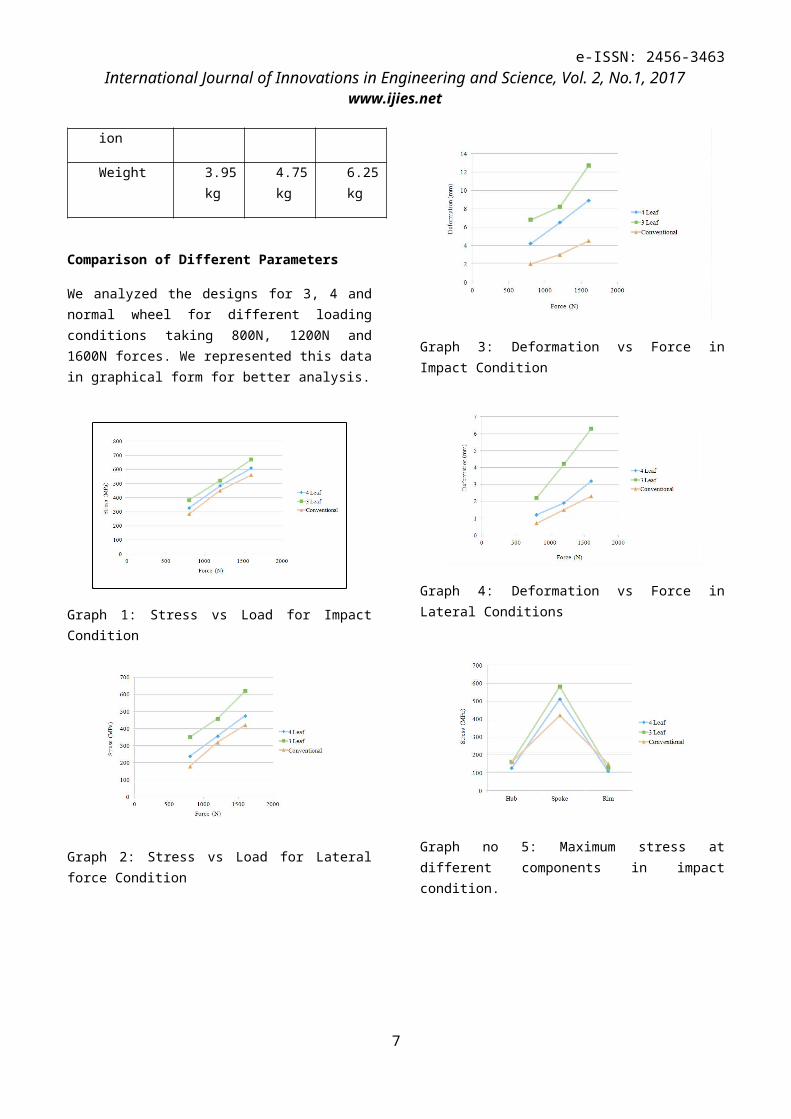
Weight 3.95 kg
4.75 kg
6.25 kg
Comparison of Different Parameters
We analyzed the designs for 3, 4 and normal wheel for different loading conditions taking 800N, 1200N and 1600N forces. We represented this data in graphical form for better analysis.
Graph 1: Stress vs Load for Impact Condition
Graph 2: Stress vs Load for Lateral force Condition
Graph 3: Deformation vs Force in Impact Condition
Graph 4: Deformation vs Force in Lateral Conditions
Graph no 5: Maximum stress at different components in impact condition.
5
e-ISSN: 2456-3463International Journal of Innovations in Engineering and Science, Vol. 2, No.1, 2017
www.ijies.net
Graph no 6: Maximum stress at different components in Lateral Condition.
Graph 7: Factor of Safety at Different Components
CONCLUSIONS
1. Comparing 3 leaf and 4 leaf design, the stresses developed in 3 leaf is very high and hence the design is discarded. The layout of spokes in conventional wheel enables proper stress distribution.
2. The main problem in the four leaf design was the high expected deflection occurring due to lateral forces. However from analysis, we can clearly see that the deformation of four leaf is 3.2mm while that in a conventional wheel is 2.2mm. Hence the problem is satisfactorily resolved.
3. The leaf or the spoke being the weakest component, the FOS for 4 leaf design is the highest. Also even after failure of leaf, the replacement of the component is simple and less expensive due to flexibility in design.
4. The drawback of the four leaf design in terms of stress and deformation against the conventional wheel design is balanced because of its ability to absorb shocks from any direction.
ACKNOWLEDGMENT
I express true sense of gratitude towards our project guide Prof. M.C. Shinde for his invaluable co-operation and the guidance that he gave me throughout the project preparation.
REFERENCES
[1] Yung-Sheng Liua*, Tswn-Syau Tsayb, Chao-Ping Chenc, Hung-Chuan Panc (“Simulation of riding a full suspension bicycle for analyzing comfort and pedaling force”) accepted 29 May 2013; ; Published by Elsevier journal (page no.84-90).
[2] Nicola Petrone, Federico Giubilato-(“Methods for evaluating the radial structural behaviour of racing bicycle wheels”) University of Padova, Italy; accepted 16 May 2011; Published by Elsevier journal (page no.88-93)
6
Prof. Mahesh ChandrabhanShindeAssistant ProfessorME (Heat Power Engineering)Mechanical Engineering DepartmentVIT Campus Kamshet Pune
Priyankal VishwakarmaB.E. StudentMechanical Engineering DepartmentVIT Campus Kamshet Pune
Priyankal VishwakarmaB.E. StudentMechanical Engineering DepartmentVIT Campus Kamshet Pune
Shevale HanumantB.E. StudentMechanical Engineering DepartmentVIT Campus Kamshet Pune
Sushant ShindeB.E. StudentMechanical Engineering DepartmentVIT Campus Kamshet Pune
e-ISSN: 2456-3463International Journal of Innovations in Engineering and Science, Vol. 2, No.1, 2017
www.ijies.net
[3] Jobst Brandt, The Bicycle Wheel Third Edition, Page 36-47.
[4] Song Yin, Yuehong Yin-(“Study on virtual force sensing and force display device for the interactive bicycle simulator”); accepted 10 June 2007 Published by Elsevier journal (page no.65-74)
[5] Covilla*, Steven Begga, Eddy Eltona, Mark Milnea, Richard Morrisa, Tim Katza-(“ Parametric finite element analysis of bicycle frame geometries”) Published by Elsevier journal (page no.441-446).