65
AEC(SA) BIM Protocol Implementing South African BIM Standards for the Architectural, Engineering and Construction industry based on international collaboration. SA BIM Protocol 1

AEC(SA) BIM ProtocolImplementing South African BIM Standards for the Architectural,
Engineering and Construction industry based on international collaboration.
SA BIM Protocol 1

TrademarksAll trademarks are the property of their respective owners.
SA BIM Protocol 2

SA BIM Protocol 3

AEC(SA) BIM PROTOCOLContents1 Introduction 5
Background – AEC(SA) 556
Scope 6Update Procedure 7Creative Commons Attribution-ShareAlike 4.0 International Public License 7
2 Legal Documents and Considerations 8
Model Release / Terms of Usage 8Model Copyright 10
3 Project Startup 12
BIM Execution Plan (BxP) 12Identification of BIM Uses 12Satisfying BIM Uses 12Information Exchanges & Software Proficiency 13Software Compatibility 13Model Structure Documented in BxP 14Templates & Standards 14
4 Interoperability 15
Introduction 15Modelling Protocols 15
5 Modelling Strategy 16
Model Development Strategy 16Content Creation 16CAD Drawing Content 16Project Location & Site Co-ordination 18Linking Models 18
6 Modelling and Data Organization 20
General Principles 20Worksets 20Element Management 20
7 Project Folders 22
Introduction 22
SA BIM Protocol 4

Shared Content Folder Structure 22Local Project Folder Structure 22Project Folder Structure 23
8 Project Naming Conventions 24
Model File Naming Conventions 24Division Naming 25View Naming 26
9 Graphics Style 27
Introduction 27AEC (SA) Compliant Materials 27Text Assignment 27Line Weights 28Line Patterns 29Line Styles 29Hatching and Filled Regions 29View Templates 29Drawing Borders and Title Blocks 29Annotation Symbols 30
10 Quality Control / Quality Assurance (QC / QA) 31
Model Maintenance 31Workshared Files 31Managing Workshared Files 31Importing and Linking Files 31Model Archiving Practice 31Electronic Exchange between Consultants 31Model Saving 31
11 3D Coordination 32
Approach 32Model Consolidation 32Coordination Meetings 32Issue Resolution 32
APPENDIX A - Definitions / Terms 33
APPENDIX B – Stamp Recommendations 38
APPENDIX C - Creative Commons Attribution - sharealike 4.0 international license 40
SA BIM Protocol 5

1 INTRODUCTIONThe AEC BIM Protocol builds on the guidelines and frameworks defined and developed by AEC (UK). BIM Institute was of the opinion that it is better to work to make an existing protocol better than to try to establish our own standards documents as well as existing, proven internal company procedures.
This document intends to provide the beginnings of a South African based compliant, platform-independent protocol for designers BIM authoring tools based on internationally recognized standards and adapted only where required to meet the South Africa AEC industry needs.
It focuses primarily on encouraging adaptation of emergent standards for practical and efficient application of BIM in South Africa, particularly at the design stages of a project.
The objectives are:
1. To maximize production efficiency through adopting a coordinated and consistent approach to working in BIM.
2. To define the standards, settings and best practices that ensure delivery of high quality data and uniform drawing output across an entire project.
3. To ensure that digital drawing files are structured correctly to enable efficient data sharing whilst working in a collaborative environment across multidisciplinary teams both internally and in external digital drawing environments.
The AEC (SA) BIM Protocol v1.0 forms the “hub” of a complete software-based solution. The supplementary documents provide the additional detail and enhancements required to implement these protocols using specific design authoring software:
· Protocol for Revit · Protocol for ArchiCAD · Supporting Documents including White Papers and Templates
Update Procedure
Proposed changes and additions to this standard should be submitted in writing to the BIM Institute with accompanying examples, discussion, or other supportive material. Feedback will be gathered, continuously reviewed, and collated to form new revisions to this document at appropriate intervals. Please post these comments and ideas to the BIM Institute.
It is expected that this standard will undergo a relatively rapid evolution process as the industry adapts to the implications and advantages of BIM methodology and once other institutions become more involved.
Creative Commons Attribution-ShareAlike 4.0 InternationalPublic License
This work is licensed under a Creative Commons Attribution-ShareAlike 4.0International License. Please see Appendix C for license details.
SA BIM Protocol 6

2 LEGAL DOCUMENTS AND CONSIDERATIONSWhen a model author seeks to electronically share the design and drawing files with another party, a Terms of Usage letter should be executed and sent out to that party for signature. Once the original Terms of Usage letter is returned bearing the signature of a person with signing authority and indicating acceptance of the Terms of Usage, the model author then releases the model for use by the other party.
Model Release / Terms of Usage
Terms of Usage from Consultant to Constructor
Signing the Terms of Usage indicates acknowledgement and acceptance that the transmitted BIM Project Files may represent an imperfect data set with the potential to contain errors, omissions, conflicts, inconsistencies, improper use of modelling components, and other inaccuracies. The Level of Development provided in the BIM Project Files should be appropriate to the contractual services and is not intended to represent construction geometry, means and methods for project delivery, or other detailed information associated with Levels of Development that form the contractual responsibilities of the Constructor:
· Information contained in BIM Project Files does not form part of the Contract Documents and is transmitted for information purposes only and is used at your own risk.
· Contract Documents will govern in the event that there is a discrepancy between BIM Project Files and the Contract Documents; the Prime Consultant will not respond to Requests for Interpretation (RFIs) arising from use of BIM Project Files.
· The information transmitted represents the current state of BIM Project Files on the date the electronic file is produced; the Prime Consultant will not issue updated versions of BIM Project Files except at the Prime Consultant’s sole discretion.
· The Constructor will remain responsible for establishing and confirming site dimensions and project conditions as well as for resolving construction issues associated with the work in accordance with the requirements of the Contract Documents.
The information requested is transmitted in a suitable file format used for production of BIM Project Files which contains the electronic design and drawing files created by the Prime Consultant:
· BIM Project Files will be issued in a self-extracting file format that requires additional acceptance of an electronic disclaimer.
SA BIM Protocol 7
and will be available from a Common data Environment (CDE) site established by the Prime Consultant’s BIM Manager or Client.
· The Constructor must obtain additional signatures for each Subcontractor with whom BIM Project Files will be shared. Procedures that bind all Subcontractors to the same Terms of Usage established in the Terms of Usage letter and as described in the project specifications must be established by the Constructor.
· The Constructor is permitted to share this information only with Subcontractors working on this project; neither the Constructor nor any Subcontractors working on this project will be permitted to transmit or share the information contained in BIM Project Files to any third party.
The information contained in BIM Project Files is provided for the convenience of the Constructor who agrees to indemnify and hold harmless the Prime Consultant to the fullest extent permitted by law from any damage, liability, or costs including and without limitation to any special, indirect, or consequential damages arising from use of BIM Project Files.
The Prime Consultant assumes no responsibility and disclaims any liability to any person or entity for any loss or damages including and without limitation to any special, indirect, or consequential damages caused by errors or omissions contained within BIM Project Files, whether resulting from negligence, accident or other cause.
Sample Disclaimer
By executing this self-extracting file, the user agrees that they will be bound by the following conditions and disclaimers:
1. The information contained in this self-extracting file was prepared to meet the express purposes of the Consultant’s contract with the Owner and relates specifically to the associated Project and Contract Documents.
2. The information in the self-extracting file does not form part of the Contract Documents unless specifically designated as such in the Project specifications.
3. The user shall not transmit the information in the self-extracting file to any third party without the prior written consent of the Consultant.
4. The consultant makes no warranty or guaranty that dimensions provided or established from electronic drawing files represent actual site conditions:
a. The user shall remain responsible for establishing and confirming site dimensions and project conditions except as limited below.
b. In the event that there is a discrepancy between electronic drawing files provided to the User and Bid Documents and Addenda, Bid Documents and Addenda shall govern.
SA BIM Protocol 8
c. In the event that dimensions are not indicated, they shall not be scaled electronically from electronic drawing files. Missing dimensions shall be brought to the attention of the Consultant, who will determine dimensions or direct method for determination of missing dimensions.
d. Bring to the attention of the consultant any discrepancies between the information provided in the self-extracting file and the Contract Documents. The consultant will, at their sole discretion, determine the correct interpretation of the information or direct the method of interpretation for the information.
5. The information in the self-extracting file is provided for the convenience of the user. The user, and any third party to which the user transmits the information, agrees to indemnify and hold harmless the Consultant to the fullest extent permitted by law from any damage, liability or costs (including, without limitation, special, indirect or consequential damages) arising from the information. The Consultant is not liable for any unauthorized use of information in the self-extracting file such as:
a. Use of supplied electronic drawing files for any subsequent Project is strictly forbidden without express written consent of the Consultant.
b. The Consultant will not be held liable for any unauthorized use or modification of electronic drawing files provided.
c. The Consultant expressly disclaims any warranty or assurance that electronic drawing files will remain accurate beyond date that files were created.
d. The Consultant assumes no responsibility and disclaims any liability to any person or entity for any loss or damages including any special, indirect or consequential damages caused by error or omissions in electronic drawing files and format provided, whether resulting from negligence, accident or any other cause.
Model Copyright
One method of protecting proprietary information in the BIM project files is to include a copyright notice on a drafting view which serves as the default when opening the model. An example of a copyright notice from IBI Group (with permission) follows:
“Any reproduction or distribution for any purpose other than authorized by Constructer is forbidden. Written dimensions shall have precedence over scaled dimensions. Contractors shall verify and be responsible for all dimensions and conditions on the job and Constructer shall be informed of any variations from the dimensions and conditions shown on the drawing. Shop drawings shall be submitted to Constructer for approval before proceeding with fabrication.”
SA BIM Protocol 9

Professional Stamps
Good practice dictates that electronic forms of professional stamps and seals should not be distributed in a reproducible format. This may be challenging if the architect or engineer is using specific BIM authoring software to stamp drawings. A final decision on this matter is beyond the scope of this report, but Appendix B contains applicable excerpts from the respective jurisdictions of governing architectural organizations.
SA BIM Protocol 10

3 PROJECT STARTUP
BIM Execution Plan (BxP)
A BIM Execution Plan (BxP) is a living, collaborative document used to communicate the overall vision and procedures for BIM implementation to project stakeholders. Developed at the early stages of a project, the BxP should continually grow and be updated according to changing project requirements. The BxP should perform the following functions:
· Identify the appropriate BIM goals and uses for the project.
· Design the BIM execution process.
· Define the BIM deliverables.
· Identify the supporting infrastructure needed to successfully implement the plan.
Identification of BIM Uses
The distinction must be made between BIM as a process to develop and transfer digital information of a building project throughout its entire life cycle and specific software application used to author some of that digital information – namely, as a tool to support BIM. Therefore, significant consideration should be undertaken to identify and verify how the BIM authoring application SA be used to satisfy specific uses of BIM based on project and team goals. The identification of BIM goals and uses, as well as other important processes used to execute BIM, should be captured in a BIM Execution Plan (BxP).
Before beginning any project, a BxP should be drafted in order to steer the direction of the modelling effort, to ensure that all parties understand the level of effort and technological infrastructure required to achieve the deliverables, and to communicate the collaboration procedures needed to successfully execute the desired BIM outcomes.
The following subsections contain considerations that should be discussed during the initial project start up meetings and documented in the BxP with regard to using any BIM authoring package as a tool to aid in the execution of a BIM project
Satisfying BIM Uses
Identify how (or if) the BIM authoring application will be used to satisfy the desired BIM uses and goals: either as a stand-alone application, utilizing third-party plug-ins, or in conjunction with other BIM software. Some common goals could include (but are not limited to):
· Design Authoring
· Existing Conditions Modelling
· Phase Planning
SA BIM Protocol 11

· Site Analysis
· Energy Analysis
· Lighting Analysis
· 3D Coordination
· Quality Control Checks
· Site Utilization Planning
· Building System Analysis
· Record Modelling
Information Exchanges & Software Proficiency
Determine the information exchanges that will occur between project participants and assess the level of effort and skill in a particular BIM authoring application that will be required to facilitate those exchanges.
· The content of this information exchange should be documented in an information-exchange worksheet or modelling matrix, detailing who will be responsible for which model element and the Level of Development (LOD) that will be required at defined project milestones.
· Clearly communicate the required LOD deliverables at various project stages in a collaborative environment and identify any possible impediments that may occur due to a lack of proficiency among modelling participants/disciplines. Identifying these potential deficiencies allows the BIM team to develop mitigation strategies to successfully overcome these challenges.
· Consider what object and project parameters will be required to satisfy required model LOD and to perform certain analysis (e.g. lighting, energy, 3D coordination) outlined as BIM deliverables in the BxP.
Software Compatibility
Ensure interoperability and compatibility of all BIM authoring software with team participants to satisfy BIM goals.
· Technological infrastructure needs should be tabled in the BxP, outlining the software and version to be employed by each discipline to achieve BIM deliverables (e.g. Design Authoring, Design Analysis, and Construction Coordination). Any incompatibility issues should be resolved prior to commencement of any modelling activities.
o Minimum hardware and technological requirements needed to facilitate these BIM processes should also be outlined in the BxP.
SA BIM Protocol 12
Model Structure Documented in BxP
A consensus must be reached by project team members on how the BIM project files will be created, organized, and controlled. This consensus should be documented in the BxP and should include the following elements:
· File naming structure
· Model structure and definition of collaboration methods
o by discipline, distinct building, site, floor, zones, and/or building system
· Measurement and coordinate system
· Use of copy/monitor function
· Agreed upon BIM & CAD standards
For detailed best practices and protocols regarding these above items, please refer to the appropriate sections found within this document.
Templates & Standards
Depending on the nature of the project as well as the needs of the client and consultants, certain defined standards may be required that are best met utilizing an application-specific template with preloaded content, generic project information, unit settings, predefined views and plotting settings.
SA BIM Protocol 13

4 INTEROPERABILITY
Introduction
Interoperability allows for the concept of geometry and data to flow smoothly between major project phases (Design, Design Development, Contract Documents, Construction, and Operation). As a guiding principle, keep models in their native authoring formats to help maintain model integrity, reduce data loss, and reduce rework. Interoperability relies heavily on the project BxP and helps facilitate data transfers.
Modelling Protocols
Modelling protocols are required for interoperability to help promote data transfer with minimal reworks and data loss. To help support downstream modelling, the protocol should be stated within the project BxP and strictly adhered to.
SA BIM Protocol 14

5 MODELLING STRATEGY
Model Development Strategy
Standard templates will be provided to facilitate a Model Development Strategy, which shall be used to develop projects in early stages as strategizing enables rapid model development and allows for very large models to be created with low hardware requirements.
EXCEPTION must be made for MEP system components. Errors can occur in swapping one MEP system component for another, and so the above methodology shall be used only on components which are not system
Content Creation
· A component may make use of Coarse, Medium and Fine levels of detail to control graphical representation.
· Creation of a project-based shared parameter file is encouraged in order to maintain consistency of variable naming during content creation. Where multiple LOD of the same element exist, care should be taken to ensure that the same shared parameters are incorporated into the objects in order to maintain data integrity.
CAD Drawing Content
· Avoid importing CAD. Transfer 2D CAD into native objects.
· When CAD data is linked into a project, the design teams shall ensure that the latest validated and checked design information is accessed directly from the project-shared area when composing drawing sheets.
· CAD Files should be purged and audited.
· Avoid CAD files using “Proxy Objects.”
· Ensure that XREFs are minimized. Bind XREFs.
· Try to avoid the use of CAD files with SHX-based fonts.
· CAD that represents content related to the building, such as Details, Sections, etc., should be inserted as detail objects.
· Try to minimize the use of CAD files required to support final documents wherever possible.
SA BIM Protocol 15

Sheet Composition Within the BIM
Project sheets should be established directly from views in the highest level BIM or federated model. Care shall be taken to ensure that any linked data is available and visible prior to the publication of documentation from the BIM.
Sheet views shall be used to ensure final document integrity.
Sheet Composition from Views/Output Files
· Views exported from the BIM for sheet compilation in CAD, or for use as a background to other drawings in CAD, shall be placed on a plain border which clearly indicates the following:
· data is provided for information purposes only
· details of the origin of the data
· date of production or issue
· Where output files are exported from the BIM for further 2D detailing in CAD, originators shall ensure that changes occurring within the BIM are correctly reflected and updated within the CAD files used to produce the final drawing.
· If data from Revit in ‘Real-World’ co-ordinates needs exporting, then the export operation must be performed from a working view (such as a floor-plan) and not from a compiled sheet view.
· Be sure to select Shared Coordinates in the export option.
· Ensure also that the correct layering standard is selected when exporting to drawing format.
Warning: The integrity of exported views/output files from within a BIM environment must be checked for accuracy and content prior to drawing compilation.
SA BIM Protocol 16
Project Location & Site Co-ordination
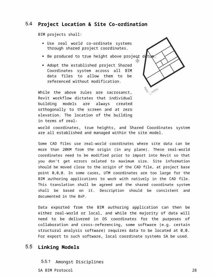
BIM projects shall:
· Use real world co-ordinate systems through shared project coordinates.
· Be produced to true height above project datum.
· Adopt the established project Shared Coordinates system across all BIM data files to allow them to be referenced without modification.
While the above rules are sacrosanct, Revit workflow dictates that individual building models are always created orthogonally to the screen and at zero elevation. The location of the building in terms of real-world coordinates, true heights, and Shared Coordinates system are all established and managed within the site model.
Some CAD files use real-world coordinates where site data can be more than 20KM from the origin (in any plane). These real-world coordinates need to be modified prior to import into Revit so that you don’t get errors related to maximum size. Site information should be moved close to the origin of the CAD file, at project base point 0,0,0. In some cases, UTM coordinates are too large for the BIM authoring applications to work with natively in the CAD file. This translation shall be agreed and the shared coordinate system shall be based on it. Description should be consistent and documented in the BxP.
Data exported from the BIM authoring application can then be either real-world or local, and while the majority of data will need to be delivered in OS coordinates for the purposes of collaboration and cross-referencing, some software (e.g. certain structural analysis software) requires data to be located at 0,0. For export to such software, local coordinate systems SA be used.
Linking Models
Amongst Disciplines
Generally, within a discipline, project templates should be duplicated using the exact same shared project coordinates and names.
Between Disciplines
Provided linked models should not change names between issued versions. All disciplines should agree to Shared Coordinates methodology.
SA BIM Protocol 17
6 MODELLING AND DATA ORGANIZATION
General Principles
A number of methods exist that enable collaborative working in a BIM environment, such as working practices and team management as well as the technological solutions covered by the remit of this document.
This section deals with the principles of segregating a model for the purposes of:
· multi-user access
· operational efficiency on large projects
· interdisciplinary collaboration
· software limitations
· hardware limitations
Different BIM authoring applications have different requirements for collaborative working. Please refer to the appropriate BIM Protocol for your specific application. If one has not yet been created please contact the BIM Institute Committee to discuss the creation of a new BIM Protocol for your specific application.
Worksets
Refer to the appropriate BIM Protocol for your specific application more information.
Element Management
Refer to the appropriate BIM Protocol for your specific application more information.
Inter-Disciplinary Model Segregation
When working within a multi-discipline environment and large complex projects, segregating a model into a number of smaller sub-models, the extents of which are to be agreed with the project team and documented within the BxP, is advisable. A Model Matrix will be required to explain and communicate the linking methodology with a key diagram to assist.
Linking model files enables additional geometry and data – this may be either other parts of a project which are too big to manage in a single file or data from another discipline or external company – to be referenced into a model.
Consider the following key points when linking files:
SA BIM Protocol 18

· Task allocation should be considered when dividing the model so as to minimize the need for users to switch between models.
· Division should be determined by the lead architect and/or engineer in conjunction with the BIM Co-ordinator and then documented in the BxP.
· The real-world coordinates should be established using “Shared Coordinates” for relinking of the models using the “Project Location” tools.
· Each sub-model should be reopened and the other sub-models linked in as required using the “Specify Shared Coordinates” insertion method.
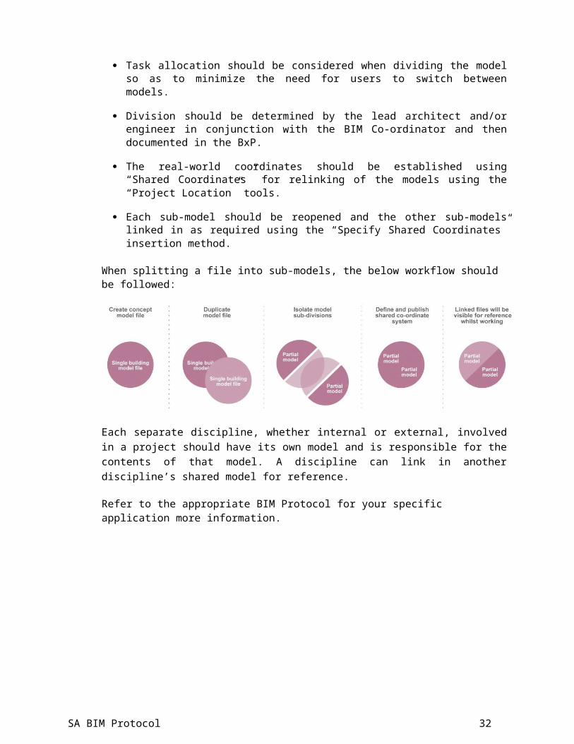
When splitting a file into sub-models, the below workflow should be followed:
Each separate discipline, whether internal or external, involved in a project should have its own model and is responsible for the contents of that model. A discipline can link in another discipline’s shared model for reference.
Refer to the appropriate BIM Protocol for your specific application more information.
SA BIM Protocol 19

7 PROJECT FOLDERS
Introduction
Project folders are an important part of being able to support multiple users on workshare-enabled projects. The following recommendations are made to establish primary content locations in order to support these shared projects.
Shared Content Folder Structure
Establishing a central resource for shared content on your networks is recommended.
· Standard templates, titleblocks, content and other non-project-specific data should be held within the server based central resource library, with restricted access.
- <SERVER NAME>\Resource\
+ Titleblocks
+ Standards
+ Templates
+ Families
All locations for the storage of family components should be sub-divided as
follows: - Content
- Architecture [Architectural components]
- Mechanical Services [MEP components]
- Structure [Structural components]
- General [Non discipline-specific elements]
- Material_Library [Textures libraries and images for render output]
Local Project Folder Structure
Refer to the appropriate BIM Protocol for your specific application more information.
SA BIM Protocol 20

SA BIM Protocol 21

Project Folder Structure
Refer to the appropriate BIM Protocol for your specific application more information.
8 PROJECT NAMING CONVENTIONS
Model File Naming Conventions
Suggested name conventions may be over-modified by removing fields not needed. What follows is an outline of possible fields that can be used from small to large projects.
Naming of model files should be based on the following:
1 2 3 4 5 6
Proj Orig Dis Zon Lev Des
Field Project (Recommended 7 digit number): An abbreviated consultant1: project number.
Field Originator (Recommended 3 characters): An abbreviated code2: identifying the originator consultant.
Field Discipline / System (Recommended 2 to 4 characters): ARCH, MECH,3: ELEC, or STRU.
Field Zone (Optional 2 characters depending on the project size and4: complexity): Identifier of which building, area, or zone of the project the
model file relates to if the project is sub-divided by building, are or zones.
Field Level (Optional 2 characters depending on the project size and5: complexity): Identifier of which level or group of levels the model file
relates to if the project is sub-divided by levels.
Field Description (Optional): Descriptive field to define the type of data6: portrayed in the file, which SA be used to describe any part of the
previous fields or to further clarify any other aspect of the contained data.. Avoid repeating information codified in other fields.
Examples
Model File Name Description
SA BIM Protocol 22
1811002-MMM-MH-14- Project 1811002, MMM Model Author, HVAC,MR.rvt
Mechanical Room, 14th floor, Central File
1811003-DLG-MECH.dgn Project 1811003, DLG Model Author,
Mechanical, Central File
1811004-MMM-ELEC.rvt Project 1811004, MMM Model Author,
Electrical, Central File
1811005-MMM-PL-A2.rvt Project 1811004, MMM Model Author,
Plumbing, Zone A2, Central File
Division Naming
Divisions should be named in a consistent and logical manner to aid navigation through the project. Note that divisions for all disciplines should be defined in the BxP so that all consultants know what to expect from linked models.
Some architectural examples follow:
0.0 Links TEMP: Any external CAD/Revit/SketchUp links for reference only – not to be printed.
0.1 Links PRINT: Any external CAD/Revit/SketchUp links TO BE PRINTED.0.2 Point Clouds: Point Clouds.0.3 Links REVIT: All Revit model links. Note that having a separate workset for
each linked model on large projects is advisable.
1.0 Structure: All structural elements including core, slabs and columns.
2.0 Vertical Connection: Stairs, elevators, escalators, etc.
3.0 Exterior Shell: Entire exterior shell of the building including any exterior doors, balconies, railings, etc.
3.5 Curtain Wall: All curtain wall components.
4.0 Interior: Walls, doors, openings, and anything inside the skin boundary that is not structural, vertical connection or furniture.
SA BIM Protocol 23

4.1 & 4.2 Furniture Layouts: All furniture and free components placed in the model.
5.0 Site: Anything that is part of the site, landscape, or softscape.
5.1 Parking: Anything that relates to surface parking or parking enclosure that is not structural or vertical connection
Refer to the appropriate BIM Protocol for your specific application more information.
View Naming
This standard is limited to drafting views and sheet views:
· A view to be used as a substructure or superstructure section. In this instance, the view property "Title on Sheet" shall be renamed to "SECTION.”
· A view to be used as a wall or framing elevation. In this instance, the view property "View Name" shall be similar to "VB-2" and the view property "Title on Sheet" shall be similarly renamed to "Framing Elevation – VB-2.”
· Level names are spelled out as they need to appear in a room schedule (as well as how they will appear in sections and elevations.) Do not pad the level number with leading zeros.
· Views shall not be named in order to make them sort or group more logically in the Project Browser as the grouping and filtering settings take care of that automatically– that is, the prefixing of level names by sequential numbers.
· View names should be written in UPPERCASE.
· View types should be created according to their use.
Creation of temporary working views is encouraged. Special views should be grouped and named to indicate their uses.
SA BIM Protocol 24

9 GRAPHICS STYLE
Introduction
This section defines the criteria that ensure the plotted appearance of drawing output from the BIM is consistent and of the highest quality. These criteria are embedded within the associated discipline-specific template files which accompany this document.
AEC (SA) Compliant Materials
Refer to the appropriate BIM Protocol for your specific application more information.
Text Assignment
This standard recommends the use of ARIAL. All text shall be restricted to the following sizes: Recommend use of ARIAL
Text heightLine Weight(mm) Plotted full Usage
sizeAllocation
1.8 2 General text, dimensions, notes –used on A3 & A4 size drawings
2.5 3 General text, Dimensions notes3.5 4 Sub-headings,
3.5 5 General text, dimensions, notes –A0 drawings
5.0 7 Normal titles, drawing numbers7.0 8 Major titles
SA BIM Protocol 25
Line Weights
Refer to the appropriate BIM Protocol for your specific application more information.
Line Patterns
Refer to the appropriate BIM Protocol for your specific application more information.
Line Styles
Line styles are defined in the supplied templates as a project setting. Any additional line styles should be created by the BIM Co-ordinator and named according to the project naming conventions described in Section 8, “Project Naming Conventions.”
Hatching and Filled Regions
· Default Fill Patterns for model and drafting, which are loaded into the default templates, should be used.
· Alternative fill patterns should be used only with the approval of the BIM Co-ordinator.
· Hatching and patterning should be created using the relevant tools available within the software.
· Where possible, hatch patterns should be assigned to the relevant materials for the elements rather than assigned as 2D patches.
· Care should be taken to ensure that the draw order and transparency settings of filled regions are appropriate to the situation so as not to cover required graphical information.
View Templates
Refer to the appropriate BIM Protocol for your specific application more information.
Drawing Borders and Title Blocks
· Corporate titleblocks are available from the families’ area of the central resource folder.
· Alternative client-specific versions may also be available from the same location.
· Project-specific titleblocks should be created and stored in the Project Resource folder.
SA BIM Protocol 26

· Logos should be native line work and filled regions rather than images
Annotation Symbols
Standard symbols such as North Point, section marks, and call-ups are available from within the discipline-specific template files and should be used by default.
Section and Detail Marks
Section and detail marks should be accessed from within standard template files, Revit’s default repository, or the central BIM library.
SA BIM Protocol 27
10 QUALITY CONTROL / QUALITY ASSURANCE (QC / QA)
Model Maintenance
Refer to the appropriate BIM Protocol for your specific application more information.
Workshared Files
Refer to the appropriate BIM Protocol for your specific application more information.
Managing Workshared Files
Refer to the appropriate BIM Protocol for your specific application more information.
Importing and Linking Files
Refer to the appropriate BIM Protocol for your specific application more information.
SA BIM Protocol 28

Model Archiving Practice
Refer to the appropriate BIM Protocol for your specific application more information.
Electronic Exchange between Consultants
Refer to the appropriate BIM Protocol for your specific application more information.
Model Saving
Refer to the appropriate BIM Protocol for your specific application more information.
SA BIM Protocol 29

11 3D COORDINATION
Approach
3D Coordination provides a means to create better designs and help identify and deal with potential issues that show up later on in the field. By creating a consolidated model, we SA then use this model as a tool to help understand individual building elements and their relationships to each other. This process relies heavily on the BxP.
Model Consolidation
Consolidating all of the project models and all of the required scopes creates the building information model. This model now becomes the data hub of the project and should incorporate an appropriate level of detail that facilitates the 3D coordination process. Modelling should take place in compliance with the project BxP – namely, the model origins. This model may be built by using BIM authoring tools or clash detection programs.
Coordination Meetings
Coordination meetings are required to highlight potential coordination issues. In order to solve potential issues at the design or construction level, these meetings need to have the right team members with the right expertise. Team members should meet on a weekly basis to discuss design issues. All potential issues need to be compiled into an interference report prior to the coordination meeting in order to maximize time and efficiency.
Issue Resolution
Resolving issues at the early design stages reduces RFIs (Requests for Information) and change orders later in the project. Identifying these problem areas prior to the release of the Consolidation Set (commonly referred to as the Issued for Construction (IFC) documents) creates better value for clients and project team members. If problems arise after the release of the Consolidation Set, and if these cannot be resolved at the weekly coordination meeting, an official RFI is created referencing the Consolidation Set documents to highlight the issue for resolution. A number of Contract Administration Instruments SA be used to this end.
SA BIM Protocol 30

APPENDIX A - DEFINITIONS / TERMS2D: Two Dimensional – This term generally refers to CAD typical drawings or contract documents.
3D: Three Dimensional – This term generally refers to models which have a Z-access dimension.
3D Coordination: Construction Information Modelling (sometimes referred to as CIM) occurs during the construction (and maintenance) process and the clash detection process when potential conflicts and issues may be identified using 3D collaboration and coordination software tools.
4D/5D: These are terms generally used in reference to associated information used in construction – 4D refers to scheduling and 5D refers to cost that is related to a BIM.
AEC: An abbreviation that stands for Architecture, Engineering, and Construction. This acronym refers to the collective of professions working in the creation and maintenance of the built environment.
AEC(SA) BIM Protocol: A practical BIM protocol aimed at eliminating technical wording of official documents in order to make BIM-related procedures and methodologies more accessible.
Asset Information Model (AIM): This term describes the set of information (documentation, graphical model, and non-graphical data) accrued in the project operation and in-use phase. (See also Project Information Model (PIM)).
BIM Execution Plan (BxP): A written plan that integrates the BIM tasks and information with all the stakeholders and processes.
BIM Protocol: This document identifies building information models that are required to be produced by the project team and puts in place specific obligations, liabilities, and associated limitations on the use of those models.
Building Information Model (BIM): A digital representation of the physical and functional characteristics of a facility using a collection of elements and/or information that serves as a shared knowledge resource for that facility. Typically, a BIM may be used from the schematic design phase right through to operations; BIM provides building owners with a high degree of reliable information.
Building Information Model Management (BIM Management): This term refers to the activity of keeping the BIM aligned with standards and uses. The BIM Manager, who is a cross-platform professional, usually undertakes this management.
Page 33 of 40
SA BIM Protocol 31
Building Information Modelling: This term describes the activities required to make the model and relate various information to that model. Building Information Modelling is the activity that creates the model as well as meaningful relationships between the model and other data, both internal and external.
buildingSMART: A non-profit organization that identifies and delivers construction, “share structured data” standards such as IFC and ISO Standards (formerly International Alliance for Interoperability (IAI)).
CAD: This abbreviation refers to Computer Aided Drawing/Drafting software tools that frequently feed/are fed by the BIM.
CIM: Please see 3D Coordination.
Cloud: This term broadly refers to computer resources used for processing storage or communication. These resources may be used in the execution of BIM projects.
COBIE (Construction Operations Building Information Exchange): A standard protocol for BIM projects in which (generally) spreadsheet-based information is progressively developed in order to document the construction process and then pass that standard on to the building operator.
Consolidation Set: Documents issued to facilitate construction by expressing the design intent.
CSI (www.csinet.org): The CSI is developing a comprehensive terminology library and dictionary for North America, thanks to a grant from the National Center for Energy Management and Building Technology.
Family: The file containing objects that may be used in a design that SA contain one or many members and that that are differentiated by changing parameter values.
Family Category: Each family usually belongs to a category to assist with filtering in a project. For example, a family category might be “trees,” which would then serve as the category for several families in a particular project.
Federated Model: The facility comprised of a number of connected but distinct, individual models representing parts of a facility. The subdivisions are often established along the lines of the consultant. However, on larger projects, the facility itself may need to be divided because of the size of the model.
IAI (International Alliance of Interoperability): The former name for buildingSMART.
IDM (Information Delivery Manual): A document that is normally part of the BIM Execution Plan.
SA BIM Protocol 32

IFC (Industry Foundation Classes): A standard XML-based IFC developed by buildingSMART. The IFC is an open source information model used for sharing data in the construction and facilities management industries.
IFC (Issued For Construction): See Consolidation Set.
IFD (International Framework Dictionary): This resource is being developed by the buildingSMART Alliance and is an open, shared, international terminology library that structures object-oriented information exchange.
Integration: This term refers to the ability to manage and communicate product and project data between software tools and collaborators, enabling the integration of business, planning, and delivery processes.
Interoperability: This term describes the ability and process to transform model data from one software platform to another. Interoperability allows access to BIM data across compliant software tools. Standards such as IFC allow interoperability between technical platforms.
IPD (Integrated Project Delivery): This is a contractual form relevant to the BIM design and construction process. At present the IPD has not been widely adopted outside the USA.
Level: This is an object used to define specific levels, which SA include floors, roofs, or other elements in a building. These levels SA define a plane that is used by objects as reference.
LOD (Level of Development): LOD scales are applied to provide a common understanding of information requirements at different stages of a project.
Mass Model: The type of model file that contains only the volumes describing a project or a component (and not the detail).
Model: This is a general term used to refer to the computer file(s) that may contain BIM data.
MASTERFORMAT: This is the recognized industry standard used for categorizing building products for more than 40 years. MasterFormat 2004 Edition replaces MasterFormat 1995, expanding the well-known "16 Divisions" to 50 Divisions of construction information.
SA BIM Protocol 33

Object: In Revit, an object is any discreet building component or element which SA be parametric, but may also be static. These building components virtually represent their real-world counterparts.
OmniClass: This is a classification system used in the USA, which is similar to (but not directly interoperable) with UniClass.
OOTB (Out of the Box): This abbreviation refers to configurations, settings, or content (families, templates, and data), which is included with the base Revit distribution.
Open BIM: An approach (orchestrated by buildingSmart) that provides accessible collaborative in-design realization and operation of buildings based on open standards and workflows.
Parameter: This is a data field that SA be used to contain information about an object, but SA also be used as a variable to drive certain physical conditions of an object. Parameters SA also be used in calculations related to objects or entire facilities.
Parametric Modelling: The approach by which a model is created and SA be modified by the changes in parameter values, or may be controlled through the creation of rules and/or constraints. Changes to parameters, rules, or constraints SA change individual objects or make large scale changes to entire models. The parametric approach must be approached carefully.
Parametric Objects: These objects SA be changed or influenced by changes to related parameters, rules, or constraints.
Permitted Purpose: This purpose relates to the facility, which is consistent with the required LOD (Level of Development) and agreed to at the BxP stage of the project.
Point Cloud: This term describes the number of ordinate data points represented in a 3D object. This cloud is generally created using LiDaR technology and SA be used and coordinated with BIM projects.
.RVT – This is the file format used by Revit.
Shared Coordinates: The means by which an abstract model’s coordinate system SA be related to the real world.
SIM (Site Information Modelling): BIM for site design, civil engineering, and construction.
XML (Extensible Markup Language): XML is a general-purpose specification for creating custom markup languages for computer software. It is classified as an extensible language because it allows the user to define the markup elements. XML's purpose is to aid information systems in sharing structured data, to encode documents, and to serialize
SA BIM Protocol 34

data. Revit makes use of several XML formats for this purpose, one example of which isLANDXML.
SA BIM Protocol 35

APPENDIX B – STAMP RECOMMENDATIONS
SA BIM Protocol 36

SA BIM Protocol 37

SA BIM Protocol 38

APPENDIX C - CREATIVE COMMONSATTRIBUTION - SHAREALIKE 4.0INTERNATIONAL LICENSEThis work is licensed under a Creative Commons Attribution-ShareAlike 4.0 International License. You are free to:
· Share - copy and redistribute the material in any medium or format
· Adapt - remix, transform, and build upon the material) for any purpose, even commercially
The licensor cannnot revoke these freedoms as long as you follow the license terms.
Under the following terms:
· Attribution — You must give appropriate credit, provide a link to the license, and indicate if changes were made. You may do so in any reasonable manner, but not in any way that suggests the licensor endorses you or your use.
· ShareAlike — If you remix, transform, or build upon the material, you must distribute your contributions under the same license as the original.
· No additional restrictions — You may not apply legal terms or technological measures that legally restrict others from doing anything the license permits.
Notices:
· You do not have to comply with the license for elements of the material in the public domain or where your use is permitted by an applicable exception or limitation.
· No warranties are given. The license may not give you all of the permissions necessary for your intended use. For example, other rights such as publicity, privacy, or moral rights may limit how you use the material.
SA BIM Protocol 39


