DIGITAL RATIO ADAPTER CONTROLLER (DRAC)LOCATIONS AND DIAGNOSIS
WHAT DOES THE DRAC DO?
WHERE DO I FIND THE DRAC?
The Digital Ratio Adapter Controller (DRAC), and since 1997 referred to as a Vehicle Speed Buffer, recieves an AC voltage signal from the Output Speed Sensor (OSS), or the Vehicle Speed Sensor (VSS). The DRAC then converts this AC voltage signal, to a digital DC voltage signal that can now be interpreted by the PCM/TCM, as well as changing the frequency of that signal and sends it in two different directions. One signal (2002 pulses) is sent to the PCM/TCM and used for upshifting the transmission, and another signal (4004 pulses) is sent to the speedometer for speedometer operation. The Anti-lock Brake System, Cruise Control and other systems also depend on an accurate vehicle speed signal from the DRAC. The DRAC helps the PCM/TCM to calculate vehicle speed by pulsing a 5 Volt DC signal sent to it by the PCM/TCM at an extremely rapid speed, via circuit number 437. The PCM/TCM will calculate vehicle speed by monitoring the amount of time between these pulses. The DRAC will also allow for changes in tire size and axle ratio to be easily adapted to the vehicle systems by using DRAC modules of different calibrations. You must however, remain within the axle ratios and tire sizes available from OEM, if you intend to use an OEM calibrated DRAC. Of course, if you are expected to diagnose and repair the "Dreaded DRAC", the first thing that you must do is FIND the "Dreaded DRAC".
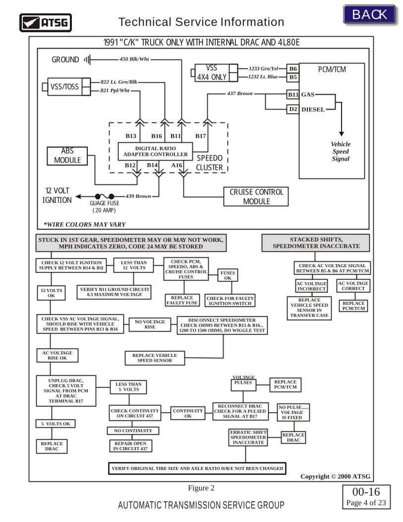
1991 "C" and "K" Trucks - DRAC would be extremely difficult to find unless you knew where to look. As you can see in Figure 1, it is an integral part of the speedometer cluster, and must be serviced or repaired as a complete assembly, as there are no service parts available for this model. Refer to Figure 2 for the diagnostic tree and internal wire schematic, for 1991 model "C/K" Trucks with the integral DRAC.
1991 "R" and "V" Trucks - On these models the DRAC is external, and is located under the lower left center of the dash, as shown in Figure 3. Refer to Figure 6 for the diagnostic tree and internal wire schematic, for 1991 "R/V" Trucks with the external DRAC. 1991 was the last year for "R/V" Trucks.Note: 1991-1993 external DRAC's are serviced only as a remanufactured item, and may have to be sent out to the remanufacturing station for repair and calibration, and then returned to you.
1991-Up "G" Series Vans - On these models the DRAC is external, and is located on the parking brake bracket, as shown in Figure 4. Refer to Figure 6 for the diagnostic tree and internal wire schematic, for the 1991-Up "G" Series Vans with the external DRAC.Note: 1991-1993 external DRAC's are serviced only as a remanufactured item, and may have to be sent out to the remanufacturing station for repair and calibration, and then returned to you.
Continued on Page 2
NOTE: Any 1995 and later truck or van equipped with an external DRAC that is mentioned in this bulletin, is NON-OBDII. Any vehicle that is OBDII certified will NOT have an external DRAC, as this function is performed internally within the Vehicle Control Module (VCM).
1992-Up (2WD) "C" Trucks - On these models the DRAC is external, and is located behind the glove box, as shown in Figure 7. Refer to Figure 6 for the diagnostic tree and internal wire schematic, for the 1992-Up (2WD) "C" Trucks with the external DRAC.Note: 1991-1993 external DRAC's are serviced only as a remanufactured item, and may have to be sent out to the remanufacturing station for repair and calibration, and then returned to you.
1992-Up "P" Series Step Vans - On these models the DRAC is external, and is located on the driver side bulkhead, as shown in Figure 8. Refer to Figure 6 for the diagnostic tree and internal wire schematic, for the 1992-Up "P" Series Step Vans with the external DRAC.Note: 1991-1993 external DRAC's are serviced only as a remanufactured item, and may have to be sent out to the remanufacturing station for repair and calibration, and then returned to you.
1993-1994 "M" & "L" Vans - On these models, which are equipped with the THM 4L60-E, the DRAC is external, and is located behind the dash and acessed by removing the glove box, as shown in Figure 9. Refer to Figure 12 for the diagnostic tree and internal wire schematic, for 1993-1994 "M" & "L" Vans equipped with the external DRAC.Note: 1991-1993 external DRAC's are serviced only as a remanufactured item, and may have to be sent out to the remanufacturing station for repair and calibration, and then returned to you.
1991 "P" Series Step Vans and Motorhome Chassis - On these models the DRAC is external, and the locations for the individual vehicles are shown in Figure 5. Refer to Figure 6 for the diagnostic tree and internal wire schematic, for the 1991 "P" Series Vans with the external DRAC.Note: 1991-1993 external DRAC's are serviced only as a remanufactured item, and may have to be sent out to the remanufacturing station for repair and calibration, and then returned to you.
1995 "M" & "L" Vans - On these models, which are equipped with the THM 4L60-E, the DRAC is external, and is located under the dash on right side of instrument cluster, as shown in Figure 10. Refer to Figure 12 for the diagnostic tree and internal wire schematic, for 1995 "M" & "L" Vans with the external DRAC.
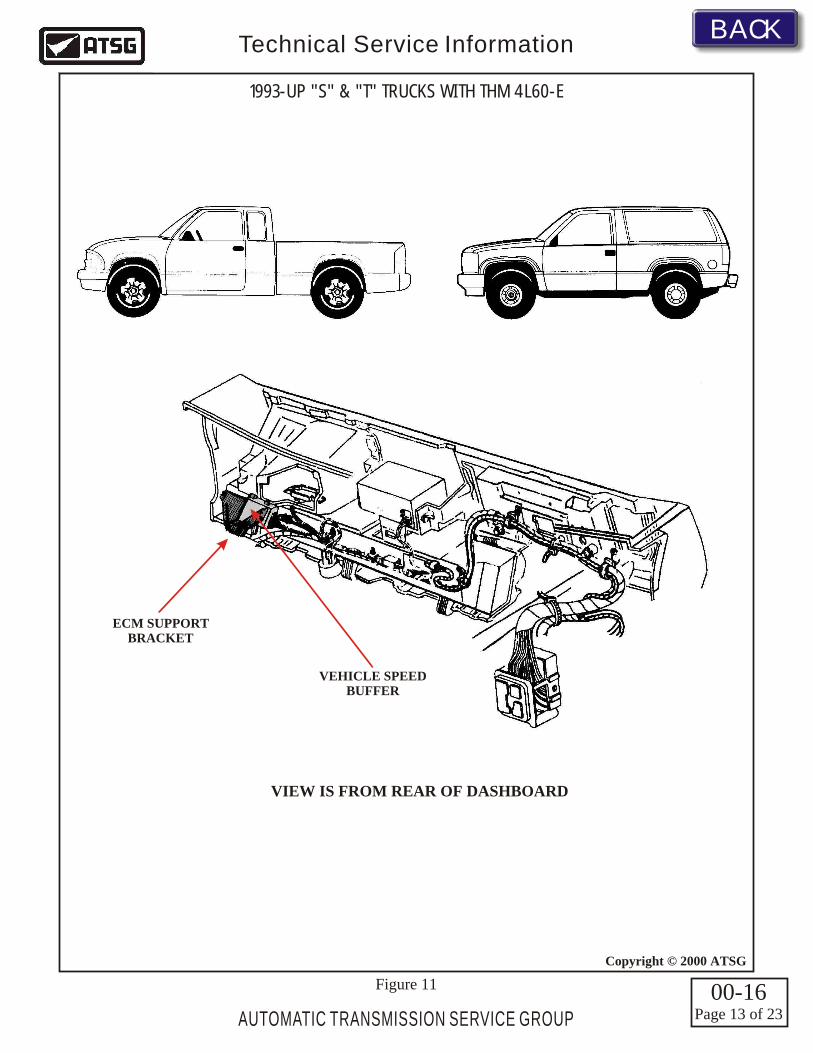
1993-Up "S" & "T" Trucks - On these models, which are equipped with the THM 4L60-E, the DRAC is external, and the location is shown in Figure 11. Refer to Figure 12 for the diagnostic tree and internal wire schematic for 1993-Up "S" (2WD) Trucks only. The 1993-Up "T" (4WD) Truck diagnostic tree and internal wire schematic is found in the 4WD section of this bulletin.Note: 1991-1993 external DRAC's are serviced only as a remanufactured item, and may have to be sent out to the remanufacturing station for repair and calibration, and then returned to you.
CHECK VSS AC VOLTAGE SIGNAL,SHOULD RISE WITH VEHICLE
SPEED BETWEEN PINS C7 &C12
DISCONNECT DRACCHECK OHMS BETWEEN C7 & C12...
1200 TO 1500 OHMS, DO WIGGLE TEST
5 VOLTS OK
LESS THAN5 VOLTS
REPLACE PCM/TCM
CHECK CONTINUITYON CIRCUIT 437
AND 1697 OR 1716
NO CONTINUITY
CONTINUITYOK
RECONNECT DRACCHECK FOR A PULSED
SIGNAL AT C13 AND C11
NO PULSE..... VOLTAGEIS FIXED
REPLACE DRAC
REPLACE DRAC ERRATIC SHIFT
SPEEDOMETERINACCURATE
VERIFY ORIGINAL TIRE SIZE AND AXLE RATIO HAVE NOT BEEN CHANGED
VOLTAGEDOES
PULSE
AUTOMATIC TRANSMISSION SERVICE GROUP
Technical Service Information
1993-UP (2WD) "S" TRUCKS WITH THM 4L60-E1993-UP "M" & "L" VANS WITH THM 4L60-E
STUCK IN 1ST GEAR, SPEEDOMETER MAY OR MAY NOT WORK,MPH INDICATES ZERO, CODES 24 OR 72 MAY BE STORED
VERIFY C8 GROUND CIRCUIT0.3 MAXIMUM VOLTAGE
CHECK 12 VOLT IGNITIONSUPPLY BETWEEN C9 & C8
REPAIR OPENIN CIRCUIT 437OR 1697 OR 1716
UNPLUG THE DRAC,TURN IGNITION ONCHECK FOR 5 VOLTSIGNAL FROM PCMAT TERMINAL C13
AND 5 VOLT SIGNALFROM PCM AT C11
Figure 12
12 V IgnitionFeed
439 Pnk/Blk439 Pnk/Blk3 Pink
824 Lt. Blu/Blk SPEEDO
*350 Pnk/Wht
437 Brown
*WIRE COLORS MAY VARY
F12
F13
C16
PCM/TCM
TransmissionOutput
Speed (RPM)VSS/TOSS
C12
C7
C8
C9
C13
C11
C14VSS Output
5 Volt Signal
5 Volt Signal
12 Volt Power
Ground
VSS Low
VSS High
DIGITAL RATIO
ADAPTERCONTROLLER
(DRAC)
822 Lt. Grn/Blk
821 Ppl/Wht
150 Black
(See Chart)
GROUNDBRAKE FUSE
(15 AMP)
INLINE FUSE(15 AMP)
12 VOLTIGNITION
TERMINAL C11WIRE CHART
1697 Brn/Wht (Truck)1716 Dk. Blue (Van)
VehicleSpeed (MPH)
00-16Page 14 of 23
BACKBACK
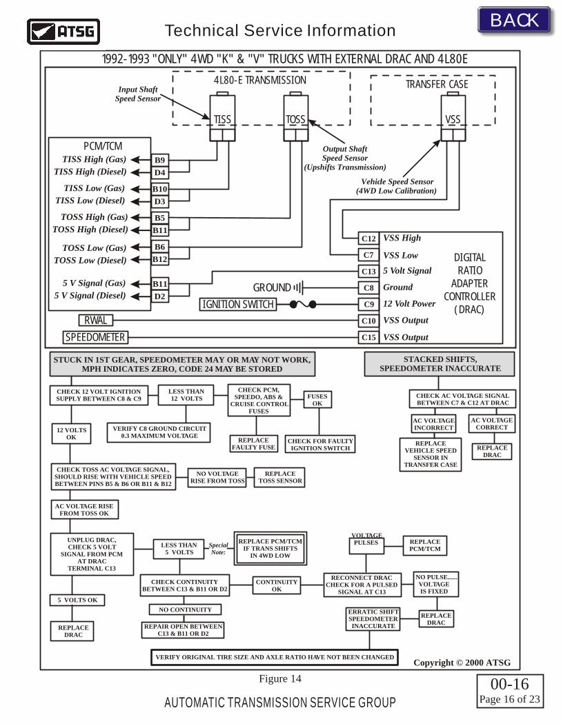
The diagnostics for this type of system require some additional diagnostic steps due to the TOSS being the speed sensor that upshifts the transmission and is "HARD WIRED" to the PCM/TCM and is internally buffered by the PCM/TCM. The VSS in the transfer case, which is wired to the DRAC is responsible for the gear reduction calibration to compensate for shift timing and speedometer accuracy that is necessary when 4 wheel low is selected. Refer to Figure 14 for the diagnostic tree and internal wire schematic, for the 1992-1993 (4WD) "K" Trucks with the external DRAC and equipped with the 4L80-E.Note: 1991-1993 external DRAC's are serviced only as a remanufactured item, and may have to be sent out to the remanufacturing station for repair and calibration, and then returned to you.
1992-1993 (4WD) "K" Trucks With 4L80-E - On these models the DRAC is external, and is found behind the glove box, which must be removed for access to the DRAC, as shown in Figure 7. This system uses only the Transmission Output Speed Sensor (TOSS) to shift the transmission and provide speedometer accuracy, as long as the transfer case is in 2WD or 4WD high. This system also compares transmission output shaft speed (TOSS) to the transfer case output speed (VSS), only when transfer case is shifted into 4WD Low, as shown in Figure 13. At this time the PCM switches strategy to compensate for the gear reduction that occured in 4WD Low, so that shift timing and speedometer operation is still accurate.
1992-1993 "ONLY" 4WD "K" & "V" TRUCKS WITH EXTERNAL DRAC AND 4L80E
C12
C7
C13
C8
C9
C10
C15 VSS Output
VSS Output
5 Volt Signal
12 Volt Power
Ground
VSS Low
VSS High
DIGITAL RATIO
ADAPTERCONTROLLER
(DRAC)
GROUND
SPEEDOMETER
IGNITION SWITCH
RWAL
B9
B5
D4
B11
B10
B6
B11
D3
B12
D2
PCM/TCM
5 V Signal (Gas)
TOSS Low (Gas)
TISS Low (Gas)
TOSS High (Gas)
TISS High (Gas)
5 V Signal (Diesel)
TOSS Low (Diesel)
TISS Low (Diesel)
TOSS High (Diesel)
TISS High (Diesel)
TRANSFER CASE4L80-E TRANSMISSION
TISS TOSS VSS
Input ShaftSpeed Sensor
Vehicle Speed Sensor(4WD Low Calibration)
Output ShaftSpeed Sensor
(Upshifts Transmission)
12 VOLTSOK
LESS THAN12 VOLTS
CHECK PCM,SPEEDO, ABS &
CRUISE CONTROLFUSES
REPLACEFAULTY FUSE
NO VOLTAGERISE FROM TOSS
REPLACETOSS SENSOR
AC VOLTAGE RISEFROM TOSS OK
FUSESOK
CHECK FOR FAULTY IGNITION SWITCH
UNPLUG DRAC,CHECK 5 VOLT
SIGNAL FROM PCMAT DRAC
TERMINAL C13
5 VOLTS OK
LESS THAN5 VOLTS
SpecialNote:
REPLACE PCM/TCM
CHECK CONTINUITYBETWEEN C13 & B11 OR D2
NO CONTINUITY
CONTINUITYOK
REPLACE PCM/TCMIF TRANS SHIFTS
IN 4WD LOW
RECONNECT DRACCHECK FOR A PULSED
SIGNAL AT C13
NO PULSE......VOLTAGEIS FIXED
REPLACE DRAC
REPLACE DRAC
REPAIR OPEN BETWEENC13 & B11 OR D2
REPLACE DRAC
ERRATIC SHIFTSPEEDOMETERINACCURATE
VERIFY ORIGINAL TIRE SIZE AND AXLE RATIO HAVE NOT BEEN CHANGED
CHECK TOSS AC VOLTAGE SIGNAL,SHOULD RISE WITH VEHICLE SPEEDBETWEEN PINS B5 & B6 OR B11 & B12
VERIFY C8 GROUND CIRCUIT0.3 MAXIMUM VOLTAGE
VOLTAGE PULSES
STUCK IN 1ST GEAR, SPEEDOMETER MAY OR MAY NOT WORK,MPH INDICATES ZERO, CODE 24 MAY BE STORED
CHECK AC VOLTAGE SIGNALBETWEEN C7 & C12 AT DRAC
AC VOLTAGEINCORRECT
REPLACE VEHICLE SPEED
SENSOR INTRANSFER CASE
STACKED SHIFTS,SPEEDOMETER INACCURATE
AC VOLTAGECORRECT
CHECK 12 VOLT IGNITIONSUPPLY BETWEEN C8 & C9
Figure 14 00-16Page 16 of 23
BACKBACK
4H2H
N 4L
The1994 & later 4x4 with 4L80E transmission and 1993 and later 4x4 with 4L60E transmission - On these models the DRAC is external, and is found behind the glove box, which must be removed for access to the DRAC, as shown in Figure 7. These utilize a 4WD Low Switch, located in the transfer case to signal the computer that 4W LOW has been selected. It does this by supplying 12V to the PCM when in 2WD or 4W HI modes. When 4W LOW is selected the 4W LOW switch grounds it's 12V signal, changing it to ZERO VOLTS. The computer, recognizing this voltage difference, then changes its strategy which adjusts for correct shift timing and speedometer operation in order to compensate for the gear reduction that occurs when 4W Low is selected.Vehicles equipped with the 4L80E transmission may have a dummy speed sensor located in the output speed sensor location, there is no wiring for this speed sensor as it is there only to plug the hole!Later models will have a plug in this location as the TOSS function on 1994 and later vehicles with the 4L80E transmission was eliminated. The VSS in the transfer case along with the 4W Low Switch takes over the functions of calibrating vehicle speed signal input, shift timing and speedometer operation and accuracy in all transfer case modes as shown in Figure 15. 1993 and later vehicles equipped with the 4L60E transmission will have the VSS in the transfer case ONLY and the 4W Low Switch located there as well. Refer to Figure 16 for the diagnostic tree and internal wire schematic, for 1994 and later "K" Trucks with the 4L80-E and 1993 and later "K" Trucks with the 4L60-E.NOTE: Even though the vehicle you are working on is a 2WD model, the vehicle harness includes the wiring for the 4 Wheel Low switch, which if grounded for what ever reason, would create a stack shifting condition. Ensure that you check the status of the 4 Wheel Low switch parameter on your scan tool, and if it says "YES", look for a grounded 1493 circuit.
AUTOMATIC TRANSMISSION SERVICE GROUP
Technical Service Information
1994 AND LATER 4WD "K" TRUCKS NON-OBDII WITH 4L80-E1993 AND LATER 4WD "K" TRUCKS NON-OBDII WITH 4L60-EFOUR WHEEL DRIVE SECTION
1993 AND LATER 4WD "T" TRUCKS NON-OBDII WITH 4L60-EFOUR WHEEL DRIVE SECTION
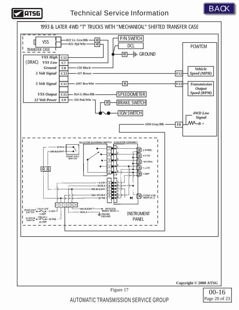
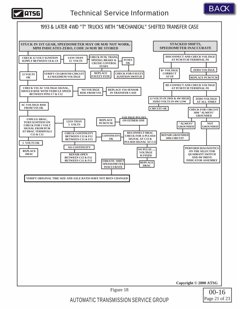
1993-Up "T" Trucks - On these models, which are equipped with the THM 4L60-E transmission, the DRAC is external, and the location is shown in Figure 11. The VSS system diagnostics for 1993 and later 4WD NON-OBDII "T" trucks becomes more involved, and will vary, depending on whether it is equipped with a mechanically shifted transfer case, or an electronically shifted transfer case. The internal wire schematic for the mechanically shifted transfer case model can be found in Figure 17, and the diagnostic tree for the mechanically shifted transfer case model can be found in Figure 18. The internal wire schematic for the electronically shifted transfer case model can be found in Figure 19, and the diagnostic tree for the electronically shifted transfer case model can be found in Figure 20.Note: 1991-1993 external DRAC's are serviced only as a remanufactured item, and may have to be sent out to the remanufacturing station for repair and calibration, and then returned to you.