57


Addendum No. 3 00901-2 SOM08416B – Somervell County WTP
and compacted by wheel rolling with light, rubber-tired or other light compaction equipment.
b. Care should be taken when backfilling the trenches to prevent any damage to the geosynthetics. At no time shall construction equipment come into direct contact with the geosynthetics. If damage occurs, it shall be repaired by the Installer prior to completion of backfill.
3. Required in-place Moisture Content and Density a. The backfill shall uniformly contain the amount of moisture within the limits specified
below necessary to obtain the maximum dry density for the soil. Compact the backfill with a moisture content within two percentage points dry to four percentage points wet of optimum moisture content.
b. The anchor trench should be backfilled and compacted to at least 95 percent of the maximum dry density as determined by ASTM D-698, Standard Proctor.
4. Testing Frequency a. The moisture and density shall be tested at a frequency of one test per 200 linear
feet per lift but no less than two tests per eight-inch lift.
A3-3 SECTION 07411 – METAL ROOF PANELS Reference Page 07411-1, Paragraph 1.02 A. 1. Replacement: Delete “standing-seam metal roof panels” and replace with “AP panels”.
A3-4 SECTION 09910 – TAPE COATING FOR STEEL Deletion: Delete Specification Section 09910 “Tape Coating for Steel” in its entirety. A3-5 SECTION 11210 – HORIZONTAL SPLIT CASE CENTRIFUGAL PUMPS Reference Page 11210-1, 1.02 A. 1. Addition: Add “Patterson” to the list of acceptable pump manufacturer. A3-6 SECTION 11260 – CHLORINE RESIDUAL ANALYZERS
A. Reference Page 11260-1, Paragraph 1.02.
Add the following to the ACCEPTABLE MANUFACTURERS list: “Prominent”
B. Reference Page 11260-2, Paragraph 2.01.H. Add Prominent to the approved equal list.
C. Reference Page 11260-3, Paragraph 3.03. Modify name from “TCL-01 (AIT-301-01)” to read “TCL-01 (AIT-602-01)
D. Reference Page 11260-3, Paragraph 3.03. Add to the table the information listed below: Equipment No. AIT-300-01; Sampling Point: Combined Finish Water; Qty. 1; Residual type: Free Chlorine; Measurement Range 0-4mg/L
A3-7 SECTION 11310 – SUBMERSIBLE SEWAGE PUMPS Reference Page 11310-1, 1.02. A. Addition: Add “KSB” to the list of acceptable pump manufacturers. A3-8 SECTION 13221 – MEMBRANE FILTRATION SYSTEM – CONFORMED
A. Reference Page, Appendix A Addition: Add Section 00400 BID FORM from the Contract Documents for the Selection of the Membrane System for Somervell County Water Treatment Plant included in this addendum.
B. Reference Page, Appendix A Addition: Add Section 00520 AGREEMENT BETWEEN BUYER AND SELLER from the Contract Documents for the Selection of the Membrane System for Somervell County Water Treatment Plant included in this addendum.
C. Reference Page, Appendix A Clarification:
Addendum No. 3 00901-3 SOM08416B – Somervell County WTP
a) Anchor bolts for membrane equipment installation to be provided by the General Contractor.
b) Cost adder for pneumatic valves to send waste to neutralization tank to be provided by the General Contractor. Cost adder for pneumatic valves: $5,000.00.
Addition: Add the recommended spare parts list per allowance bid item #2 from Pall included in this addendum.
A3-9 SECTION 13541 – PRECAST WIRE WOUND PRE-STRESSED CONCRETE TANK
A. Reference Page 13541-4, 1.05 G. 2. Modification: Modify the paragraph by replacing minimum shotcrete cover of “2” inch with 1/2 inch.
B. Reference Page 13541-9, 2.06, B. Deletion: Delete this bullet item in its entirety.
A3-10 SECTION 13900 – INSTRUMENTATION
A. Reference Page 13900-4, Paragraph 2.03.H. Modification: Modify the following sentence “ The flow tubes shall be Type PMT as
manufactured by the PFS or Badger Meter Manufacturing Company, Milwaukee, Wisconsin, or other approved equal with a lab test of uncalibrated accuracy and loss measurement for each of the flow tubes furnished or an exact duplicate of each.” to read “The flow tubes shall be Type PMT as manufactured by the PFS or equal as manufactured by BIF.”
B. Reference Page 13900-4, Paragraph 2.04.B. Modification: The following manufacturers are acceptable: Foxboro and Rosemount. The approved manufacturers shall provide an equal to the DP specified.
C. Reference Page 13900-6, Paragraph 2.10.E. Add Krohne as an acceptable Electromagnetic Flow Transmitter manufacturer.
D. Reference Page 13900-6, Paragraph 2.10.C. Add the following sentence to the paragraph: “The flow meter transmitter shall be capable of being remotely mounted 300’ from the flow tube. The LUM-FIT flow tube and flow transmitter shall not use more than 15kW DC power together. All other flow meters shall operate on 120V.”
A3-11 SECTION 14320 – TROLLEY HOISTS
A. Reference Page 14320-3, 3.04 Schedules Addition: Add the following schedule to the table
Location Equip.
Number
Hoist
Capacity (tons)
Wire Rope or Chain*
Electric or Chain Driven
Lift Height (ft)
Minimum Raised Hook Elevation
1080 PS Bldg TH-1 2 Chain Chain Driven 6
A3-12 SECTION 15114 – PILOT OPERATED SOLENOID CONTROL VALVE Addition: Add the Specification 15114 “Pilot Operated Solenoid Control Valve” included in this
addendum. A3-13 SECTION 15136 – MISCELLANEOUS VALVES Replacement: Delete this section in its entirety and replace it with the revised specification
15136 “Miscellaneous Valves” A3-14 SECTION 15815 – METAL DUCTS
A. Reference Page 15815-4, Paragraph 3.01 B.
Addendum No. 3 00901-4 SOM08416B – Somervell County WTP
Deletion: Delete “All ducts shall be aluminum.” A3-15 SECTION 16111 - CONDUITS
A. Reference Page 16111-5, Paragraph 3.01.A.15. Addition: 15. Light tight non-metallic conduit shall include grounding bushings and have a
ground wire the length of the conduit connecting both ends. A3-16 SECTION 16130 – OUTLET BOXES
A. Reference Page 16130-1, Paragraph 1.02.
Add the following to the ACCEPTABLE MANUFACTURERS list: “Appleton Steel City Thomas and Betts”
B. Reference Page 16130-1, Paragraph 1.04. Add the following to the STANDARDS list: “NEMA FB 1”
C. Reference Page 16130-1, Paragraph 2.01.B. Clarification: Sheet metal boxes shall only be allowed walls were recessed boxes are to be installed.
D. Reference Page 16130-1, Paragraph 2.01.C. Clarification: Cast boxes shall be installed in water treatment areas, electrical rooms, compressor rooms, chemical rooms, and mechanical rooms.
A3-17 SECTION 16131 – PULL AND JUNCTION BOXES
A. Reference Page 16131-1, Paragraph 2.01.A.
Modification: Modify the paragraph by deleting "Exposed wall recessed pull and junction boxes shall be 304 stainless steel.", and adding the following "Exposed pull and junction boxes in the water treatment space, chemical rooms, electrical rooms, mechanical rooms, service area, high service pump station, and any other potential wash down area, shall be NEMA 4X 304 stainless steel. Pull and junction boxes (exposed and recessed) above lay in ceilings shall be galvanized sheet metal."
DRAWINGS: A3-18 SHEET CC-4, SEQ.14
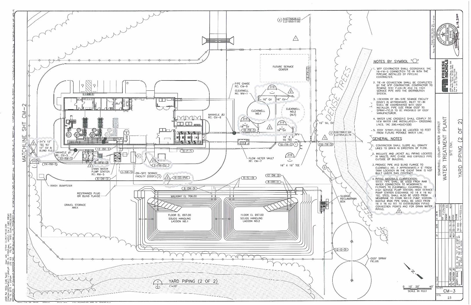
Modification: Modify the finish floor elevation in the Clearwell No. 1 and Clearwell No. 2 (ALT) from 705.0 as shown in the drawing to 704.0.
A3-19 SHEET CC-5, SEQ.15 Clarification: The gradations for both the 12” & 18” deep riprap shall be in accordance with
NCTCOG standard specifications with a corresponding 6” deep bedding gradation. The gradation for the flexbase shall be in accordance with TxDOT Item 247 (Crushed Limestone Base).
A3-20 SHEET CC-6, SEQ.16, DETAIL 9 Modification: Modify the re-bar spacing callout in the 7” paving on the left side of the detail from
“#4 BARS @ 12” C/C, EW” to “#3 BARS @ 18” C/C, EW” A3-21 SHEET CM-1, SEQ. 21, NOTE 3 Clarification: Fence and gate shall be furnished and installed by others. The General Contractor
shall provide only the electrical operator for the gate and the frame post for the electrical gate operator. The General Contractor shall coordinate the installation of the electrical gate operator with the Owner. The time of installation of the fence and gate will be determined by the Owner.
A3-22 SHEET CM-4, SEQ. 24
Addendum No. 3 00901-5 SOM08416B – Somervell County WTP
A. Reference: Section 2 Modification: Change the callout for pipe support from “340/TYPE D, TYP FOR 6” TO “340/TYPE G, TYP FOR 4”
B. Reference: Section 3 Modification: Change the callout for pipe to drain water pump station from “8-NPW-S” to “8-NPW-DI”.
A3-23 SHEET CM-9, SEQ. 29, SECTION 3
Modification: Modify the callout for the pipe channel material in the pipe chase from Aluminum to Stainless Steel as shown below. L 2”x2”x1/4” ALUMINUM S.S.
A3-24 SHEET MA-2, SEQ. 34, NOTES FOR ‘BUILDING AREA AND HEIGHT LIMITATIONS: (TABLE
503)’ Addition: Add “(ALLOWABLE)” as shown below. F-1 1 STORY/8500 SF (ALLOWABLE) H-4 2 STORY/6500 SF (ALLOWABLE) A3-25 SHEET MA-9, SEQ. 41, DETAIL 5 Clarification: The 6” c-channel at the top of the wall panel to be structural steel A3-26 SHEET MA-12, SEQ. 44, PLAN 5 Addition: Add “McKinley type EXTS Waterproof Trench and Cover’ to the callout in the office
building “5”x3” trench box for electrical”. A3-27 SHEET MA-12, SEQ. 44, ROOM FINISH SCHEDULE (CONT.) TABLE Modification: Change ceiling to read ACT-2 in rooms Laboratory (No. 103) and Break (No. 105)
A3-28 SHEET MA-12, SEQ. 44, INTERIOR MATERIAL FINISH SCHEDULE (CONT.) TABLE Addition: Under “Ceiling” add ACT-2, RFP Tile, Kemlite, Glasbord P, white. A3-29 SHEET MM-1, SEQ. 45, PLAN
A. Modification: Change the callout for the pipe connecting the strainer pad wash water vault and drain water pump station from “8-NPW-S” to “8-NPW-DI”.
B. Addition: Add detail reference “329/TYP. B” to the callout “2” FILL OUTLET RE: SHT MP-2”. A3-30 SHEET MS-1, SEQ. 52, SECTION CUT 6
Modification: Modify section cut 6 referencing from 6/MS-1/CS-1 as shown in the drawing to 6/MS-1/MS-4.
A3-31 SHEET FM-2, SEQ. 66 Clarification: Containment platform and scales for the chemical totes shall be provided by the
General Contractor. The approved model number for the containment platform and scales are as noted in Sheet FM-2.
A3-32 SHEET WM-7, SEQ. 75, SECTION 2, BAFFLE WALL ELEVATION
Modification: Modify the finished floor elevation from 705.0 as shown in the drawing to 704.0. A3-33 SHEET RM-1, SEQ. 79 Deletion: There is a note on the left side of the Solids Handling Lagoon #1, “12” PIPE AND
BLIND FLANGE” that points to a gate valve. Delete the gate valve. Only 12” pipe and blind flange will be required.
A3-34 SHEET RM-4, SEQ. 82, DETAIL 3, LAGOON DETAILS Clarification: Foot traffic is allowed on the geomembrane. The supports required for the forms
and reinforcement should not penetrate the geomembrane. If the geomembrane is punctured, then repairs should be made prior to concrete placement. The HDPE liner will be tested prior to placement of the concrete.

Addendum No. 3 00901-6 SOM08416B – Somervell County WTP
A3-35 SHEET PI-2, SEQ. 88
A. Clarification: Turbidity Analyzer AIT-301-01 will be provided by the Membrane Supplier Manufacturer.
B. Modification: Modify FCL2 analyzer from “AE-300-01” and “AIT-300-01” to read “AE-302-01” and “AIT-302-01” respectively. For clarification: Contractor will be responsible to provide the analyzer and connect to SCADA.
C. Modification: Modify LE from “LE-501-02” to read “LE-501-01”
D. Modification: Modify “LSLL-502-01” to read “LSL-502-01”
E. Modification: Modify “LSL-503-01” to read “LSH-503-01”
F. Modification: Modify “LSHH-504-01” to read “LSHH-504-01”
A3-36 SHEET PI-3, SEQ. 89
A. Modification: Modify the reference to another sheet symbol text located in the Chemical
Injection Manhole #2 from “E/PI-5” to read “B/PI-5”.
B. Modification: Add equipment circle next to TCL AE-602-01 to read “AIT-602-01” A3-37 SHEET PI-4, SEQ. 90
A. Modification: Modify the reference to another sheet symbol text labeled “TO CHEMICAL
INJECTION MANHOLE #1” such that “B/PI-2” is included in the boxes.
B. Modification: Modify the reference to another sheet symbol text labeled “TO MEMBRANE FILTRATE PIPE INJECTION POINT” such that “C/PI-2” is included in the boxes.
C. Modification: Modify the reference to another sheet symbol text labeled “TO CHEMICAL INJECTION MANHOLE #2” such that “D/PI-3” is included in the boxes.
A3-38 SHEET PI-5, SEQ. 91
A. Modification: Modify the reference to another sheet symbol text located in the Chemical
Injection Manhole #2 from “B/PI-2” to read “B/PI-3”. A3-39 SHEET PI-6, SEQ. 92
A. Reference the 900 Ground Storage Tank No. 1 Loop.
Modify the last tag number at the top of the loop to “900GST1-LSH”. Modify the text below “TO LOOPS” to “703-01,02,03”.
B. Reference the Intrusion Detection Loop. Modify the twelfth tag number to “GRDP6-XE1”. Modify the thirteenth tag number to “GRDP6-XE2”. Modify the fourteenth tag number to “GRDP6-XE3”.
A3-40 SHEET PI-9, SEQ. 95
A. Deletion: Delete Loop 301-01. Membrane Supply Manufacturer shall provide analyzer.

Addendum No. 3 00901-7 SOM08416B – Somervell County WTP
B. Addition: Add Loop 302-01. Contractor shall provide Free Chlorine analyzer and provide signals similar to Loop 500-01.
A3-41 SHEET E-2, SEQ. 102
A. Reference: Detail 1: Modify the duct bank detail call out in the top left hand corner of the drawing from “1, E-2/E-26” to read “3, E-2/E-26”. Only one callout will change.
B. Reference: Detail 1:
Correct a word in NOTE BY SYMBOL 5. Replace “APPROVES” with “APPROVED”. A3-42 SHEET E-3, SEQ. 103
A. Reference: Detail 1. Add the following as NOTE BY SYMBOL 10: “PROVIDE SUMP PUMP IN MANHOLE. PROVIDE 2 #10, #10G., 2”C. FROM PANEL LP2 CIRCUIT 29. MOUNT WP, GFI RECEPTACLE 48” ABOVE MANHOLE FLOOR AND PROVIDE NEMA 3R RECEPACLE COVER THAT MAINTAINS THE NEMA 3R RATING WHILE IN USE.” Add the NOTE BY SYMBOL identifier with a 10 at the manhole just west of the plant entrance (~45’) on the north side of the parking lot.
B. Reference: Detail 1.
Modify the duct bank detail call outs going to pole mounted light fixtures “H” from “17, E-3/E-26” to read “16, E-3/E-26”. There are a total of three callouts needing modifications.
C. Reference: Detail 1.
Modify power conductor sizes for LIT-400-01 and LIT-400-02 (at the clearwells) from “2 #6, #8G., 2”C.” to “2 #10, #10G, 1”C.”
D. Reference: Detail 1.
Modify the reference in NOTE BY SYMBOL 1 from “1/E-22” to “1/E-23”. E. Reference: Detail 1.
Modify the last sentence in NOTE BY SYMBOL 4 from “POWER CONDUCTORS FROM POWER SUPPLY TO PTZ CAMERA SHALL BE 2 #14, #14G.” to read “POWER CONDUCTORS FROM POWER SUPPLY TO PTZ CAMERA SHALL BE 2 #12, #12G.”
F. Reference: Detail 1.
Add dashed line between duct bank callout 12 and 13 on the south side of the building. The dashed line shall go from the building to duct bank callout 18 and shall be labeled duct bank callout “18, E-3/E-26”.
A3-43 SHEET E-4, SEQ. 104
A. Reference: Detail 1. Modify all duct bank callouts with “E-3” in the lower left corner to “E-4”. There are a total of four duct bank callouts requiring modifications.
B. Reference: Detail 1.
Modify transformer label “TX1” to “T-1” C. Reference: Detail 1.
Modify power conductor label “GEN-01C” to “GEN-01P”
A3-44 SHEET E-7, SEQ. 107
A. Reference: Detail 1.
Addendum No. 3 00901-8 SOM08416B – Somervell County WTP
Modify wire tag “PIT-601C” to read “PIT-6011C”
B. Reference: Detail 1. Modification: Add two VFDs to the MCC room 112 wall for a total of 6 VFDs. Add two additional feeders from SWB-1 to the VFD’s. The feeders shall be labeled SWB-05P and SWB-06P.
A3-45 SHEET E-9, SEQ. 109
A. Reference: Detail 1. Modify sheet continuation reference on duct bank callout 14 from “1/E-2” to “1/E-3”.
B. Reference: Detail 1. Add duct bank callout “10, E-9/E-26” to the dashed line with Note by Symbol 7.
C. Reference: Detail 1. Add dashed line and a duct bank callout “18, E-9/E-26” between duct bank callouts 12 and 13.
D. Reference: Detail 1. Modify the dashed line from lighting contactor noted with a Note By Symbol 6 to terminate at SWB-1. Modify the dashed line noted with a Note By Symbol 7 to be routed to Panel “HA” instead of SWB-1.
E. Reference: Detail 1. Modification: Modify number of VFD’s in MCC Room 112 to show a total of 6. The Pall PLC may move east to make room. There will be three VFDs per membrane skid, a total of six VFDs mounted to the wall. The Note By Symbol 19 leaders shall also point to the two additional VFDs.
F. Reference: NOTE BY SYMBOL. Modify the first sentence in Note By Symbol 16 from “2 sets of 3 #6, #10G., 2”C.(RGS).” to “3 sets of 3 #6, #10G., 4”C.(RGS).”. For Clarification there are three set of conductors and conduit for each dashed line (to each membrane skid). Conductor tags for these three lines are as follows; top dashed line = FP-01P, FP-02P, RFP-01P; middle dashed line= FP-03P, FP-04P, RFP-02P; Bottom dashed line are spare conduits (three 4” conduits).
G. Reference: NOTE BY SYMBOL. Modify the first sentence in Note By Symbol 18 from “PROVIDE SPARE 2-4”” to “3 sets of 3 #6, #10G., 2”C.(RGS).”.
A3-46 SHEET E-10, SEQ. 110
A. Reference: Detail 1. Modify wire tag “LP1B-15” to read “LP1B-5”.
B. Reference: Detail 1.
Add wire tag “LP1-39” to the wire tag list with all the other LP1 wire tags. C. Reference: Detail 1.
Add the Note by Symbol with a 13 inside on the exhaust fan. D. Reference: Detail 4.
Add duct bank call out “17, E-10/E-26” to dashed line with wire tags SCMP-01P and SCMP-01C.
E. Reference: NOTE BY SYMBOL 12.
Modify the first sentence in Note By Symbol 12 from “MOUNT DPIT TO 2” PIPE STAND PER DETAIL.” to read “MOUNT DPIT TO 2” PIPE STAND PER DETAIL, RE: 1/E-24”
Addendum No. 3 00901-9 SOM08416B – Somervell County WTP
A3-47 SHEET E-12, SEQ. 112
A. Reference: Detail 1. Add wire tag “FSD-01P” to the load labeled MEMBRANE SID NO. 1.
B. Reference: Detail 1.
Add wire tag “FSD-02P” to the load labeled MEMBRANE SID NO. 2. C. Reference: Detail 1.
Delete the Note By Symbol 10 shown next to the Neutralization Pump combination motor starter disconnect.
F. Reference: NOTE BY SYMBOL 4. Modify the second sentence in NOTE BY SYMBOL 4 from “75HP FEEDER IS TEMPORARY...” to read “100HP FEEDER IS TEMPORARY…”
G. Reference: Detail 1. Addition: Add two additional feeders in SWB-1. Each feeder will have: one (1) 60A, 3P circuit breaker, 3 #4, #10G.,1-1/2”C. (to the VFD), and 3 #6, #10G.,4”C. from the VFD to the Feed Pumps (1 and 2) on the second Membrane skid. Feed Pump No.1 (on skid 2) wire tags shall be SWB-05P and FP-03P. Feed Pump No. 2 (on skid 2) wire tags shall be SWB-06P and FP-04P. Wire tags FP-03P and FP-04P shall have a Note By Symbol with the number 10 next to it. The VFDs in line with the feeders shall have Note By Symbols 1 and 6 next to the VFD (similar to Feed Pumps 1 and 2 shown).
H. Reference: Detail 1. Modification: Modify SWB-01P, SWB-02P, SWB-03P, SWB-04P wire tags to each include a 1-1/2”C.
I. Reference: Detail 1. Modification: Modify the “100A, 2P” circuit breaker feeding the 50kVA transformer to read “150A, 2P”. Modify conductors labeled T2-01P from “2 #1/0, #6G., 3”C.” to read “2 #2/0, #6G., 3”C.”
A3-48 SHEET E-13, SEQ. 113
A. Reference: Detail 1. Add the following notes for the detail: “3. DETAIL SHOWN IS GENERAL AND VOLTAGES SHOWN MAY VARY DEPENDING ON
POWER SOURCE LOCATION AND FIXTURE SCHEDULES. 4. ENCLOSURES MOUNTED OUTSIDE SHALL BE NEMA 4X 316 STAINLESS STEEL.”
A3-49 SHEET E-17, SEQ. 117
A. Reference: Panel LP-2. Modify circuit 29 from “SPARE” to read “N. MANHOLE SUMP PUMP”.
A3-50 SHEET E-20, SEQ. 120
A. Reference: Detail 1. Delete the Note By Symbol 1 next to the MCS Power Supply (just to the right of the DX8116 DVR).
A3-51 SHEET E-26, SEQ. 126
A. Reference: Detail 1. Modify conduit 2 name from “PHONE” and make it read “SPARE”.

Addendum No. 3 00901-10 SOM08416B – Somervell County WTP
B. Reference: Detail 4. Modify conduit 5 name from “LP1B-01” and make it read “LP1B-5”.
C. Reference: Detail 5. Modify conduit 2 name from “ELAM01-P1, ELAM01-P2, ELAM02-P1, ELAM02-P2” and
make it read “ECAM01-P1, ECAM01-P2, ECAM02-P1, ECAM02-P2” respectively.
D. Reference: Detail 4. Modify conduit 5 name from “SPARE” and make it read “LP2-29”.
E. Reference: General Note on sheet.
Add the following general note: “1. SPARE CONDUITS TERMINATED IN MANHOLES AND PULL BOXES SHALL
BE PLUGGED WITH AN EXPANDABLE RUBBER SEALOFF USING STAINLESS STEEL HARDWARE.”
A3-52 SHEET PE-2, SEQ. 152
A. Reference: Detail 1. Modify Cable Tag No. “900GST1-XEC” located on the ground storage tank to “900GST1-XE1C”.
Modify Instrument Tag No. “900GST1-XEC” located on the ground storage tank to “900GST1-XE1”.
B. Reference: Detail 2.
Add the cable tag “COAX” to the ductbank. The Conduit for the “COAX” shall be a 3” Conduit in the ductbank.
A3-53 SHEET PE-3, SEQ. 153
A. Reference: “NOTES BY SYMBOL” Modify Note By Symbol No. 1 to read “Not Used” Modify Note By Symbol No. 6 to read “RTU with a NEMA 3R enclosure. Connect RTU to PS1-6. Provide 2#12, #12G., 3/4”C.” Modify Note By Symbol No. 11 the circuit number in the second sentence from “PS1-11” to “PS1-10”.
B. Reference: Detail 3. Modify Instrument Tag No. “1080-XE2C” located at the roll up door to “1080-XE2”.
Modify Instrument Tag No. “1080-XE1C” located at the man door to “1080-XE1”. Modify the 2” Conduit for the “COAX” for the ductbank entering the east side of the to a 3” conduit Add cable tag no. “DP1-05P” to the homerun for “EUH-1”. Add cable tag no. “DP1-06P” to the homerun for “EUH-2”.
C. Reference: Detail 4.
Modify the Detail No. 2 for the duct bank exiting east from the valve vault to Detail No. 3. Modify the Detail No. 3 for the duct bank exiting west from the valve vault to Detail No. 2. Modify the cable tag callouts for the conduits between the junction boxes in the valve vault as follow:
Addendum No. 3 00901-11 SOM08416B – Somervell County WTP
Add “900GST1-LSH1C” to the 2” conduits containing “900GST1-ZSC”.
Add the intrusion switch for the valve vault hatch to Detail 4. The cable tag shall be “900GST1-XE2C”. The instrument tag shall be “900GST1-XE2”. Reference “No. 4 Notes By Symbol” for Detail No. 4. Add Note By Symbol No. 5. Note By Symbol No. 5 shall read as follows: “Provide 2#10, #10G., 3/4”C.”.
A3-54 SHEET PE-4, SEQ. 154
A. Reference Detail No. 1 Modify the motor horsepower connected to cable tag “P1-01P” to 30. Modify the motor horsepower connected to cable tag “P2-01P” to 30. Modify the motor horsepower connected to cable tag “P3-01P” to 30.
Add the following to No.1 Notes By Symbol No. 3: “Coordinate MCP rating and overloads with motor manufacturer prior to ordering.
B. Reference the interconnection diagram.
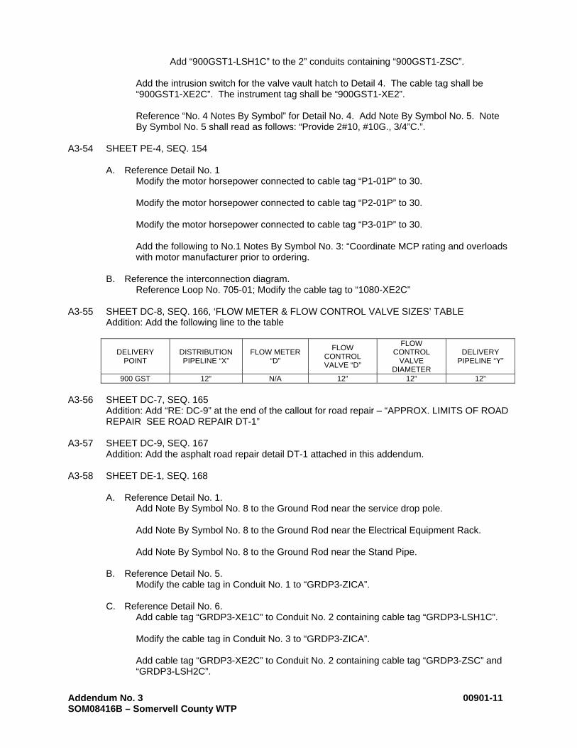
Reference Loop No. 705-01; Modify the cable tag to “1080-XE2C” A3-55 SHEET DC-8, SEQ. 166, ‘FLOW METER & FLOW CONTROL VALVE SIZES’ TABLE Addition: Add the following line to the table
DELIVERY POINT
DISTRIBUTION PIPELINE “X”
FLOW METER “D”
FLOW CONTROL VALVE “D”
FLOW CONTROL
VALVE DIAMETER
DELIVERY PIPELINE “Y”
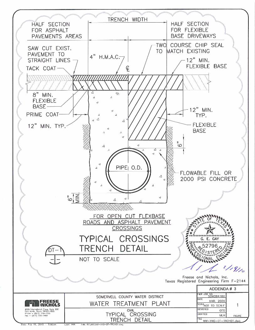
900 GST 12” N/A 12” 12” 12” A3-56 SHEET DC-7, SEQ. 165 Addition: Add “RE: DC-9” at the end of the callout for road repair – “APPROX. LIMITS OF ROAD
REPAIR SEE ROAD REPAIR DT-1” A3-57 SHEET DC-9, SEQ. 167 Addition: Add the asphalt road repair detail DT-1 attached in this addendum. A3-58 SHEET DE-1, SEQ. 168
A. Reference Detail No. 1. Add Note By Symbol No. 8 to the Ground Rod near the service drop pole. Add Note By Symbol No. 8 to the Ground Rod near the Electrical Equipment Rack. Add Note By Symbol No. 8 to the Ground Rod near the Stand Pipe.
B. Reference Detail No. 5.
Modify the cable tag in Conduit No. 1 to “GRDP3-ZICA”.
C. Reference Detail No. 6. Add cable tag “GRDP3-XE1C” to Conduit No. 2 containing cable tag “GRDP3-LSH1C”. Modify the cable tag in Conduit No. 3 to “GRDP3-ZICA”. Add cable tag “GRDP3-XE2C” to Conduit No. 2 containing cable tag “GRDP3-ZSC” and “GRDP3-LSH2C”.

Addendum No. 3 00901-12 SOM08416B – Somervell County WTP
A3-59 SHEET DE-2, SEQ. 169
A. Reference the Loop 704-02 in the Interconnection Diagram. Modify the Equipment Description to read “Flow Meter Vault High Water Level Alarm”.
B. Reference the Loop 704-03 in the Interconnection Diagram. Modify the Equipment Description to read “Valve Vault High Water Level Alarm”.
A3-60 SHEET DE-3, SEQ. 170
A. Reference Detail No. 1. Modify Note By Symbol in the Ground Mat near the service drop to Note By Symbol No. 13.
Add Note By Symbol No. 8 to the Ground Rod near the service Stand Pipe. Add Note By Symbol No. 8 to the Ground Rod near the Electrical Equipment Rack.
B. Reference Detail No. 5.
Modify the cable tag in Conduit No. 1 to “GRDP4-ZICA”. Modify the first cable tag in Conduit No. 2 to “GRDP4-ZSC”.
C. Reference Detail No. 6.
Modify the cable tag in Conduit No. 3 to “GRDP4-ZICA”. Modify the first cable tag in Conduit No. 4 to “GRDP4-ZSC”.
D. Reference Detail No. 7.
Modify the cable tag in Conduit No. 3 to “GRDP4-ZICA”. Modify the first cable tag in Conduit No. 4 to “GRDP4-ZSC”.
A3-61 SHEET DE-4, SEQ. 171
A. Reference the Loop 704-04 in the Interconnection Diagram. Modify the Equipment Description to read “Flow Meter Vault High Water Level Alarm”.
B. Reference the Loop 704-05 in the Interconnection Diagram. Modify the Equipment Description to read “Valve Vault High Water Level Alarm”.
A3-62 SHEET DE-5, SEQ. 171
A. Reference “NOTES BY SYMBOL” Modify Note By Symbol No. 2 to read “Not Used”. Clarification: The underground electrical to the service entrance disconnect shall be provided by the Electric Utility Company.
B. Reference Detail No. 1. Add Note By Symbol 8 to the Ground Rod near the service entrance disconnect for the Ground Mat.
Add Note By Symbol No. 8 to the Ground Rod near the service Stand Pipe. Add Note By Symbol No. 8 to the Ground Rod near the Electrical Equipment Rack.
C. Reference Detail No. 2.
Delete Detail No. 2. Detail No. 2 is Not Used.
Addendum No. 3 00901-13 SOM08416B – Somervell County WTP
D. Reference Detail No. 4. Modify the Note By Symbol for the ground conductor that follows the duct bank to Note By Symbol No. 15.
E. Reference Detail No. 5.
Modify the cable tag in Conduit No. 1 to “GRDP5-ZICA”. Modify the first cable tag in Conduit No. 2 to “GRDP5-ZSC”.
F. Reference Detail No. 6.
Modify the cable tag in Conduit No. 3 to “GRDP5-ZICA”. Modify the first cable tag in Conduit No. 4 to “GRDP5-ZSC”.
G. Reference Detail No. 7.
Modify the cable tag in Conduit No. 3 to “GRDP5-ZICA”. Modify the first cable tag in Conduit No. 4 to “GRDP5-ZSC”.
A3-63 SHEET DE-6, SEQ. 173
A. Reference the Loop 704-06 in the Interconnection Diagram. Modify the Equipment Description to read “Flow Meter Vault High Water Level Alarm”.
B. Reference the Loop 704-07 in the Interconnection Diagram. Modify the Equipment Description to read “Valve Vault High Water Level Alarm”.
A3-64 SHEET DE-7, SEQ. 174
A. Reference Detail No. 1. Add Note By Symbol 8 to the Ground Rod that is shown to be connected to the service entrance disconnect for the Ground Mat.
Add a ground rod near the stub-up for the COAX for the antenna on the Existing Ground Storage Tank. Add Note By Symbol No. 8 to this ground rod. Add Note By Symbol No. 10 to this ground rod. Add Note By Symbol No. 8 to the Ground Rod near the Electrical Equipment Rack.
B. Reference Detail No. 2.
Delete Detail No. 2. Detail No. 2 is Not Used.
C. Reference Detail No. 4. Add cable tag “GRDP6-XE1C” to Conduit No. 2.
D. Reference Detail No. 5.
Modify the cable tag in Conduit No. 1 to “GRDP6-ZICA”. Modify the first cable tag in Conduit No. 2 to “GRDP6-ZSC”. Add cable tag “GRDP6-XE2C” to Conduit No. 2.
E. Reference Detail No. 6.
Add cable tag “GRDP6-XE1C” to Conduit No. 2. Modify the cable tag in Conduit No. 3 to “GRDP6-ZICA”. Modify the first cable tag in Conduit No. 4 to “GRDP6-ZSC”.
Addendum No. 3 00901-14 SOM08416B – Somervell County WTP
Add cable tag “GRDP6-XE2C” to Conduit No. 4.
F. Reference Detail No. 7. Add cable tag “GRDP6-XE1C” to Conduit No. 2. Modify the cable tag in Conduit No. 3 to “GRDP6-ZICA”. Modify the first cable tag in Conduit No. 4 to “GRDP6-ZSC”. Add cable tag “GRDP6-XE2C” to Conduit No. 4.
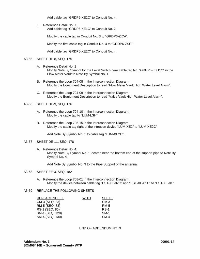
A3-65 SHEET DE-8, SEQ. 175
A. Reference Detail No. 1 Modify Note By Symbol for the Level Switch near cable tag No. “GRDP6-LSH1C” in the Flow Meter Vault to Note By Symbol No. 1.
B. Reference the Loop 704-08 in the Interconnection Diagram.
Modify the Equipment Description to read “Flow Meter Vault High Water Level Alarm”.
C. Reference the Loop 704-09 in the Interconnection Diagram. Modify the Equipment Description to read “Valve Vault High Water Level Alarm”.
A3-66 SHEET DE-9, SEQ. 176
A. Reference the Loop 704-10 in the Interconnection Diagram.
Modify the cable tag to “LUM-LSH”.
B. Reference the Loop 705-15 in the Interconnection Diagram. Modify the cable tag right of the intrusion device “LUM-XE2” to “LUM-XE2C” Add Note By Symbol No. 1 to cable tag “LUM-XE2C”.
A3-67 SHEET DE-11, SEQ. 178
A. Reference Detail No. 4.
Modify Note By Symbol No. 1 located near the bottom end of the support pipe to Note By Symbol No. 4.
Add Note By Symbol No. 3 to the Pipe Support of the antenna.
A3-68 SHEET EE-3, SEQ. 182
A. Reference the Loop 708-01 in the Interconnection Diagram. Modify the device between cable tag “EST-XE-02C” and “EST-XE-01C” to “EST-XE-01”.
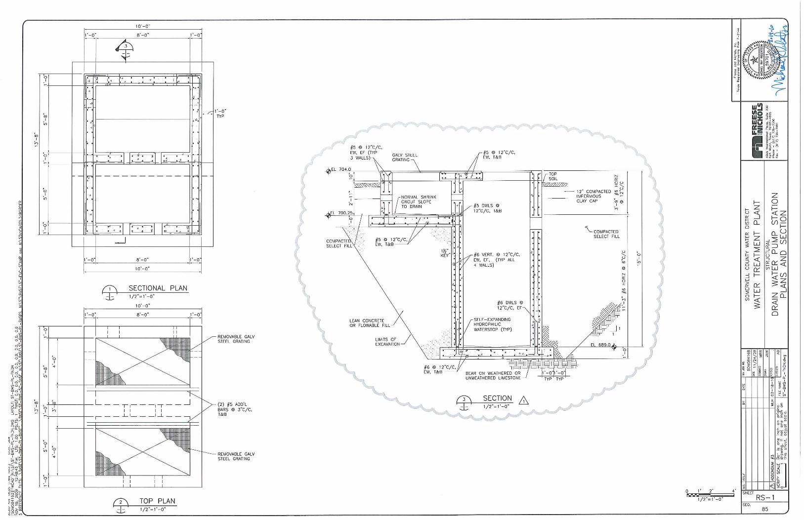
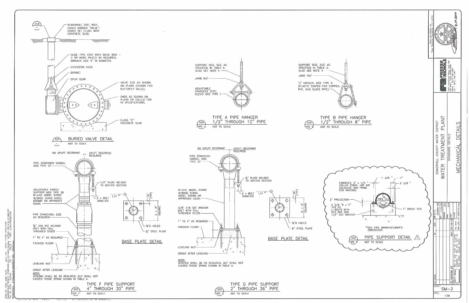
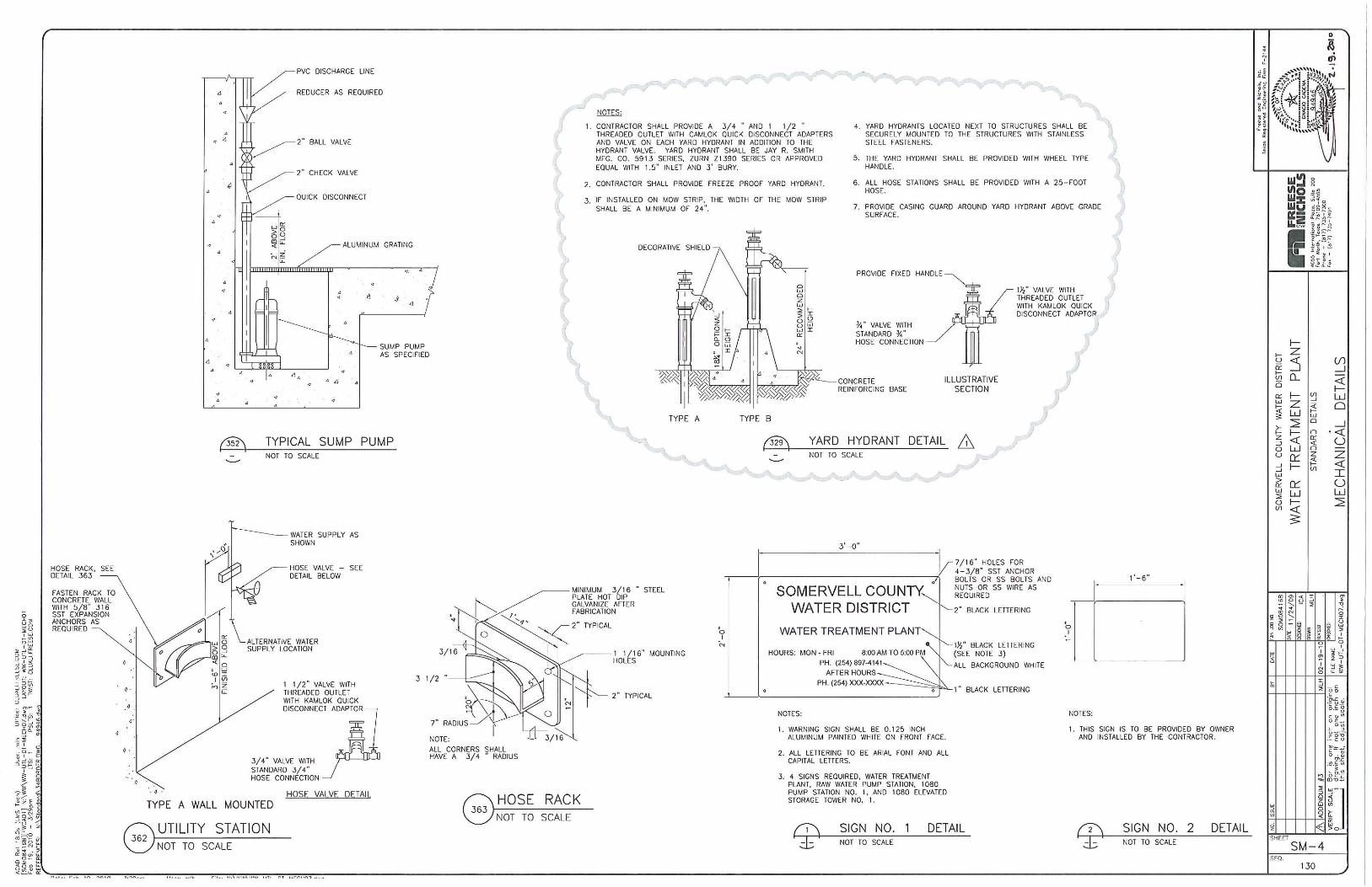
A3-69 REPLACE THE FOLLOWING SHEETS
REPLACE SHEET WITH SHEET CM-3 (SEQ. 23) CM-3 RM-5 (SEQ. 83) RM-5 RS-1 (SEQ. 85) RS-1 SM-1 (SEQ. 128) SM-1 SM-4 (SEQ. 130) SM-4
END OF ADDENDUM NO. 3


Agreement Between Buyer and Seller SOM08416B – Somervell County WTP 00520-1
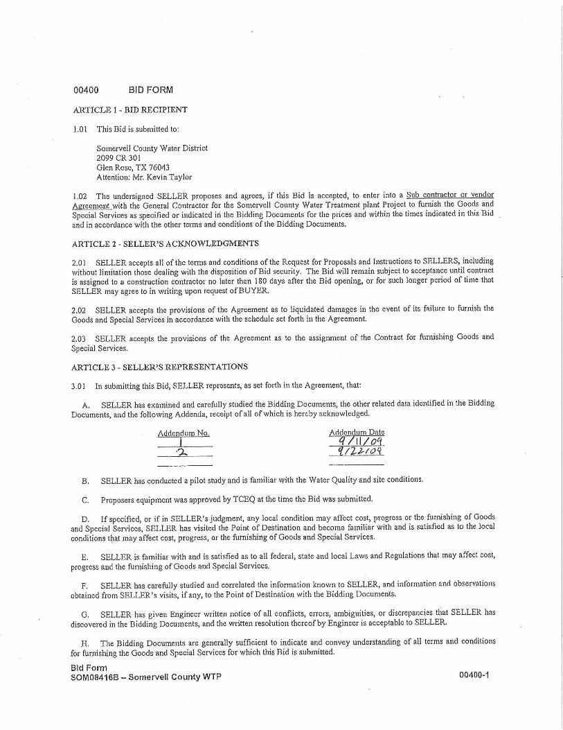
00520 AGREEMENT BETWEEN BUYER AND SELLER
THIS AGREEMENT is between SOMERVELL COUNTY WATER DISTRICT (“Buyer”) and
(“Seller”). Buyer and Seller, in consideration of the mutual covenants set forth herein, agree as follows: ARTICLE 1 - GOODS AND SPECIAL SERVICES 1.01 Seller shall furnish the Goods and Special Services as specified or indicated in the Contract Documents. The Goods and Special Services to be furnished are described in Contract Documents. ARTICLE 2 - THE PROJECT 2.01 The Project for which the Goods and Special Services to be provided under the Contract Documents may be the whole or only a part is generally described as follows: SOMERVELL COUNTY WATER TREATMENT PLANT PROJECT ARTICLE 3 - ENGINEER 3.01 The Contract Documents for the Goods and Special Services have been prepared by:
Freese and Nichols, Inc. 4055 International Plaza, Suite 200 Fort worth, TX 76109-4895
who is hereinafter called Engineer and who is to assume all duties and responsibilities, and have the rights and authority assigned to Engineer in the Contract Documents in connection with the furnishing of Goods and Special Services. ARTICLE 4 - POINT OF DESTINATION 4.01 The place where the Goods are to be delivered is defined in the General Conditions as the Point of Destination and is designated as: Somervell County Water District 2099 County Road 301 Glen Rose, TX 76043 ARTICLE 5 - CONTRACT TIMES 5.01 Time of the Essence A. All time limits for Milestones, if any, the delivery of Goods and the furnishing of Special Services as stated in the Contract Documents are of the essence of the Contract. 5.02 Date for Submittal of Shop Drawings A. All Shop Drawings and Samples required by the Contract Documents will be submitted to Buyer for Engineer’s review and approval. 5.03 Date for Delivery of Goods A. The Goods are to be delivered to the Point of Destination and ready for Buyer’s receipt of delivery 120 days after shop drawing approval or 270 days from the Buyers selection notice. Whichever occurs first. Note: SELLER to coordinate storage and delivery of goods with Construction Contractor prior to delivery. 5.04 Not Used

Agreement Between Buyer and Seller SOM08416B – Somervell County WTP 00520-2
5.05 Liquidated Damages A. Buyer and Seller recognize that time is of the essence of this Agreement and that Buyer will suffer financial loss if the Goods are not delivered at the Point of Destination and ready for receipt of delivery by Buyer within the times specified in Paragraph 5.03 above, plus any extensions thereof allowed in accordance with Article 7 of the General Conditions. The parties also recognize that the timely performance of services by others involved in the Project are materially dependent upon Seller’s specific compliance with the requirements of Paragraph 5.03. Further, they recognize the delays, expense and difficulties involved in proving the actual loss suffered by Buyer if complete acceptable Goods are not delivered on time. Accordingly, instead of requiring such proof, Buyer and Seller agree that as liquidated damages for delay (but not as a penalty) Seller shall pay Buyer $750.00 for each day that expires and not to exceed 20% of the contract price after the time specified in Paragraph 5.03 for delivery of acceptable Goods. ARTICLE 6 - CONTRACT PRICE 6.01 Buyer shall pay the Construction Contractor to which this agreement is assigned for furnishing the Goods and Special Services in accordance with the Contract Documents in current funds as follows: A. The prices stated in Seller’s suggested bid form attached hereto as Exhibit A. Construction Contractor will make payments to the Seller in compliance with the Terms and Conditions of this agreement as paid by the Buyer. ARTICLE 7 - PAYMENT PROCEDURES 7.01 Submittal and Processing of Payments. A. Seller shall submit Applications for Payment to the Construction Contractor in accordance with Article 10 of the General Conditions. Applications for Payment will be processed by Engineer as provided in the General Conditions. 7.02 Progress Payments. A. Buyer shall make progress payments on account of the Contract Price on the basis of Seller’s applications for Payment as submitted through the construction contractor as follows:
1. Upon receipt of the first Application for Payment submitted in accordance with Paragraph 10.01.A.1 of the General Conditions and accompanied by Engineer’s recommendation of payment in accordance with Paragraph 10.02.A of the General Conditions, an amount equal to ten (10%) percent of the Contract Price, less such amounts as Engineer may determine in accordance with Paragraph 10.02.A.3 of the General Conditions.
2. Upon receipt of the second such Application for Payment accompanied by Engineer’s recommendation of payment in accordance with Paragraph 10.01.A.2 of the General Conditions, an amount sufficient to increase total payments to Seller to 80% percent of the Contract Price, less such amounts as Engineer may determine in accordance with Paragraph 10.02.A.3 of the General Conditions.
7.03 Final Payment A. Upon receipt of the final Application for Payment accompanied by Engineer’s recommendation of payment in accordance with Paragraph 10.06 of the General Conditions, Buyer shall pay the remainder of the Contract Price as recommended by Engineer. ARTICLE 8 - INTEREST 8.01 Buyer is not obligated to pay interests on Moneys not paid except as provided in Section 49.276 (d) of the Texas Water Code. ARTICLE 9 - SELLER’S REPRESENTATIONS 9.01 In order to induce Buyer to enter into this Agreement, Seller makes the following representations:
Agreement Between Buyer and Seller SOM08416B – Somervell County WTP 00520-3
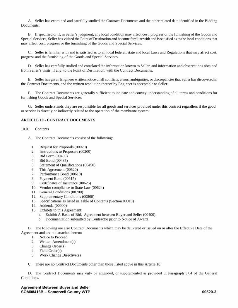
A. Seller has examined and carefully studied the Contract Documents and the other related data identified in the Bidding Documents. B. If specified or if, in Seller’s judgment, any local condition may affect cost, progress or the furnishing of the Goods and Special Services, Seller has visited the Point of Destination and become familiar with and is satisfied as to the local conditions that may affect cost, progress or the furnishing of the Goods and Special Services. C. Seller is familiar with and is satisfied as to all local federal, state and local Laws and Regulations that may affect cost, progress and the furnishing of the Goods and Special Services. D. Seller has carefully studied and correlated the information known to Seller, and information and observations obtained from Seller’s visits, if any, to the Point of Destination, with the Contract Documents. E. Seller has given Engineer written notice of all conflicts, errors, ambiguities, or discrepancies that Seller has discovered in the Contract Documents, and the written resolution thereof by Engineer is acceptable to Seller. F. The Contract Documents are generally sufficient to indicate and convey understanding of all terms and conditions for furnishing Goods and Special Services. G. Seller understands they are responsible for all goods and services provided under this contract regardless if the good or service is directly or indirectly related to the operation of the membrane system. ARTICLE 10 - CONTRACT DOCUMENTS 10.01 Contents A. The Contract Documents consist of the following:
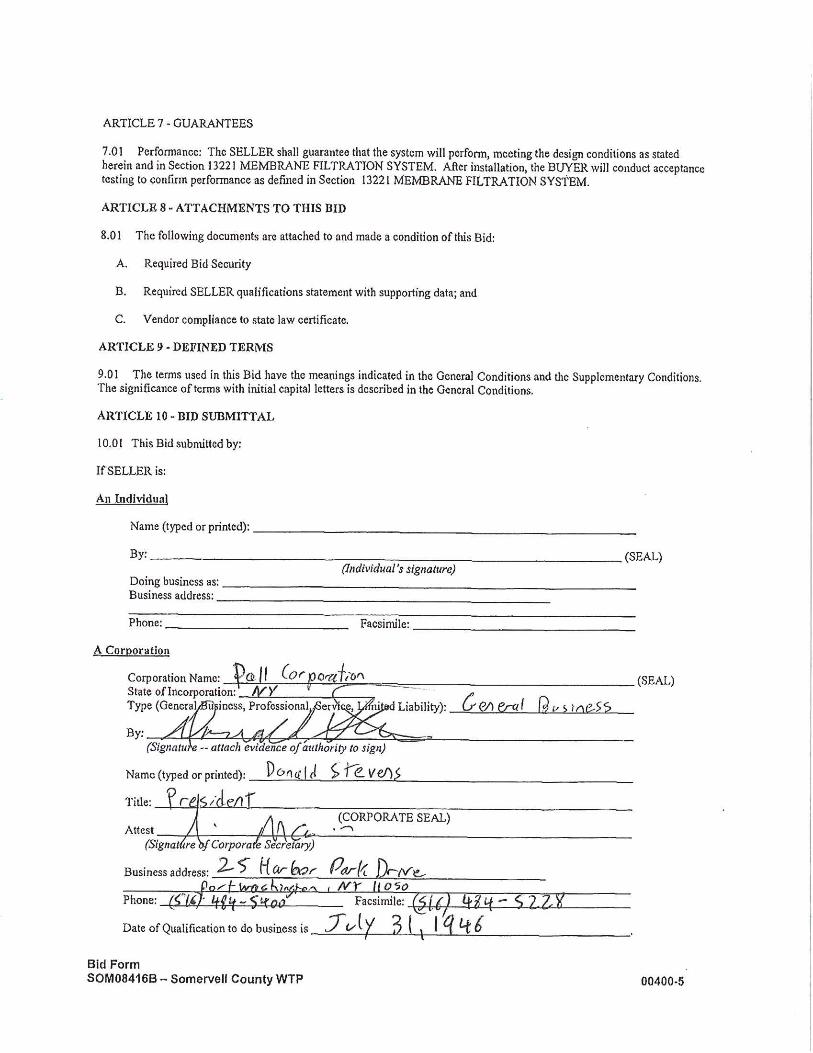
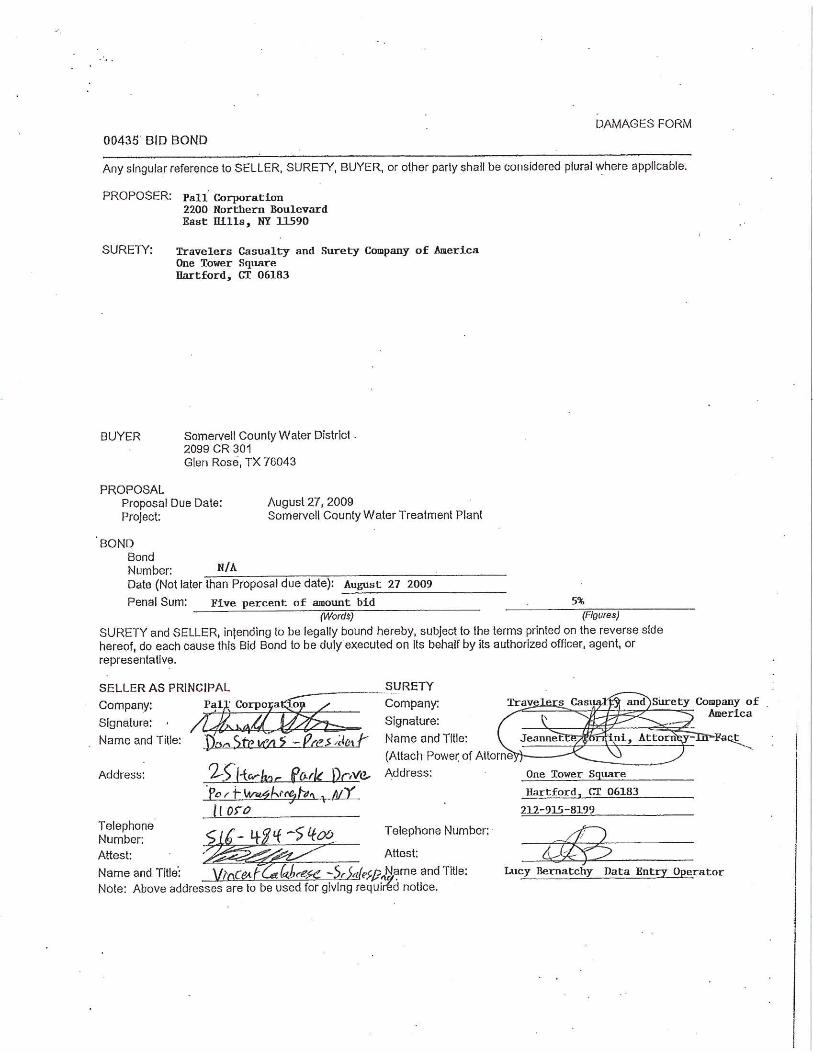
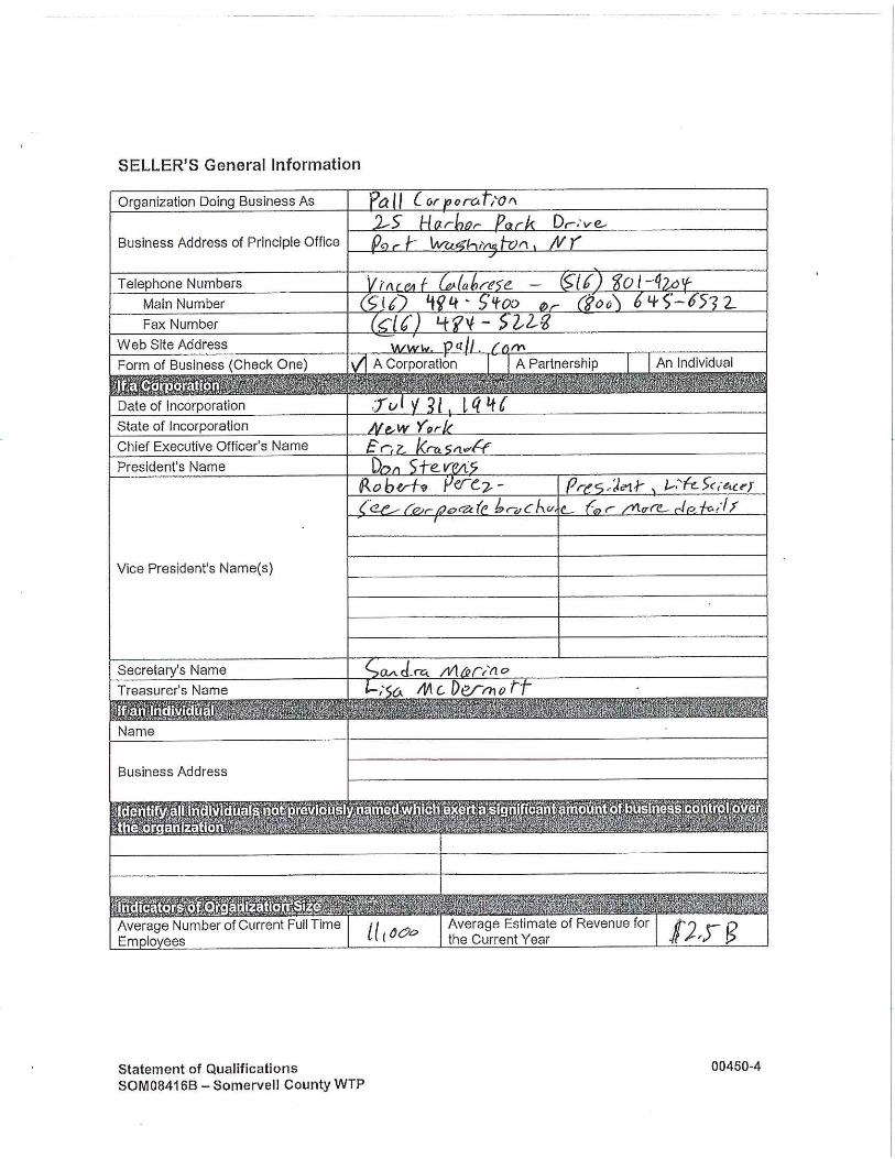
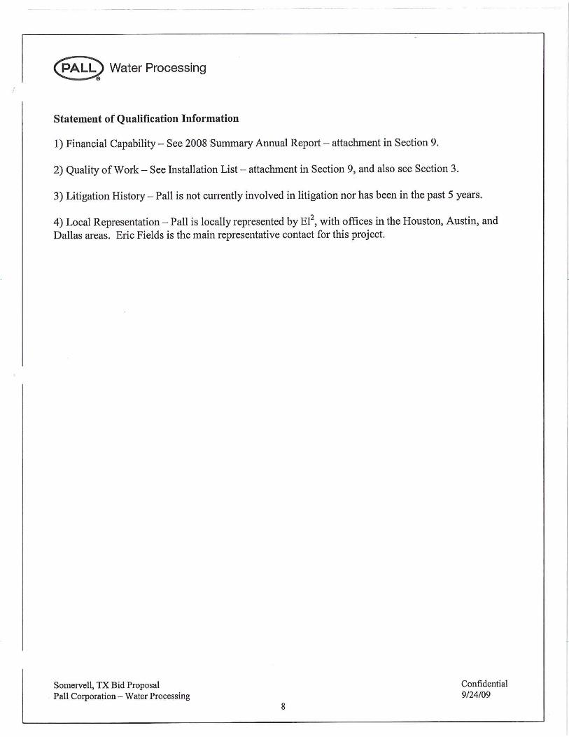
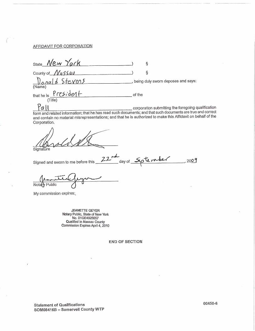
1. Request for Proposals (00020) 2. Instructions to Proposers (00200) 3. Bid Form (00400) 4. Bid Bond (00435) 5. Statement of Qualifications (00450) 6. This Agreement (00520) 7. Performance Bond (00610) 8. Payment Bond (00615) 9. Certificates of Insurance (00625) 10. Vendor compliance to State Law (00624) 11. General Conditions (00700) 12. Supplementary Conditions (00800) 13. Specifications as listed in Table of Contents (Section 00010) 14. Addenda (00900) 15. Exhibits to this Agreement:
a. Exhibit A Basis of Bid. Agreement between Buyer and Seller (00400). b. Documentation submitted by Contractor prior to Notice of Award.
B. The following are also Contract Documents which may be delivered or issued on or after the Effective Date of the Agreement and are not attached hereto:
1. Notice to Proceed 2. Written Amendment(s) 3. Change Order(s) 4. Field Order(s) 5. Work Change Directive(s)
C. There are no Contract Documents other than those listed above in this Article 10. D. The Contract Documents may only be amended, or supplemented as provided in Paragraph 3.04 of the General Conditions.

Agreement Between Buyer and Seller SOM08416B – Somervell County WTP 00520-4
ARTICLE 11 - MISCELLANEOUS 11.01 Defined Terms A. Terms used in this Agreement will have the meanings indicated in the General Conditions and the Supplementary Conditions. 11.02 Assignment A. Buyer has the right and intends to assign the Contract for furnishing Goods and Special Services hereunder and Seller shall accepts such assignment. Forms documenting the assignment of the Contract, and consent of Seller’s surety to the assignment are attached as exhibits to this Agreement.
1. The Contract will be executed in the name of Buyer initially, and will be assigned to a Construction Contractor designated by Buyer. The assignment will occur on the effective date of the agreement between Buyer and the Construction Contractor, which is expected to occur within 180 days from the signing of this agreement. As of the date of acceptance of assignment by the Construction Contractor, all references in the Contract Documents to Buyer shall mean the Construction Contractor whose responsibilities will include the installation of the Goods.
2. The assignment of the Contract shall relieve Buyer from all further obligations and liabilities under the Contract. After assignment, Seller shall become a subcontractor or supplier to the assignee and, except as noted herein, all rights, duties, and obligations of Buyer under the Contract shall become the rights, duties and obligations of the assignee.
3. After assignment:
a. All performances warranties and guarantees required by the Contract Documents will continue to run for the
benefit of Buyer and, in addition, for the benefit of the assignee. b. Except as provided in this Paragraph 11.02.A.3.b, all rights, duties and obligations of Engineer to assignee and
Seller under this Contract will cease.
1) Engineer will review Seller’s Applications for Payment and make recommendations to assignee for payments as provided in Paragraphs 10.02 and 10.06 of the General Conditions.
2) Upon the written request of either the assignee or Seller, Engineer will issue with reasonable promptness such clarifications or interpretations of the Contract Documents, which shall be consistent with or reasonably inferable from the overall intent of the Contract Documents. Such written clarifications and interpretations will be final and binding on assignee and Seller unless:
a) an appeal from Engineer’s clarification or interpretation is made within the time limits and in accordance with the dispute resolution procedures set forth in Article 13 of the General Conditions; or
b) if no such dispute resolution procedures have been set forth, a written notice of intention to appeal is delivered by assignee or Seller to the other within 30 days after the date of such decision, and a formal proceeding is instituted by the appealing party in a forum of competent jurisdiction within 60 days after the date of such decision (unless otherwise agreed to in writing by assignee and Seller), to exercise such rights or remedies as the appealing party may have with respect to such clarification or interpretation in accordance with applicable Laws and Regulations.
3) When rendering a clarification or interpretation under Paragraph 11.02.A.3.b.2, Engineer will not show partiality to assignee or Seller and will not be liable in connection with any clarification or interpretation rendered in good faith.
B. No other assignment by a party hereto of any rights under or interests in the Contract Documents will be binding on another party hereto without the written consent of the party sought to be bound. Specifically but without limitation, moneys that may become due and moneys that are due may not be assigned without such consent (except to the extent that the effect of this restriction may be limited by law). Unless specifically stated to the contrary in any written consent to an assignment, no assignment will release or discharge the assignor from any duty or responsibility under the Contract Documents.

Agreement Between Buyer and Seller SOM08416B – Somervell County WTP 00520-5
11.03 Successors and Assigns A. Buyer and Seller each binds itself, its partners, successors, assigns and legal representatives to the other party hereto, its partners, successors, assigns and legal representatives in respect to all covenants, agreements and obligations contained in the Contract Documents. 11.04 Severability A. Any provision or part of the Contract Documents held to be void or unenforceable under any Law or Regulation shall be deemed stricken, and all remaining provisions shall continue to be valid and binding upon Buyer and Seller. The Contract Documents shall be reformed to replace such stricken provision or part thereof with a valid and enforceable provision that comes as close as possible to expressing the intention of the stricken provision.
Agreement Between Buyer and Seller SOM08416B – Somervell County WTP 00520-6
IN WITNESS WHEREOF, Buyer and Seller have signed this Agreement in duplicate. One counterpart each has been delivered to Buyer and Seller. All portions of the Contract Documents have been signed or identified by Buyer and Seller or on their behalf. This Agreement will be effective on [insert date]. Buyer: SOMERVELL COUNTY WATER DISTRICT Seller: PALL CORPORATION By: By: [Corporate Seal] [Corporate Seal] Attest: Attest: Address for giving notice: Address for giving notice: (If Buyer is a corporation, attach evidence of Agent for service of process: authority to sign. If Buyer is a public body, attach evidence of authority to sign and resolution or other documents authorizing execution of Buyer-Seller Agreement.) (f Seller is a corporation or a partnership, attach evidence of authority to sign.) Designated Representative: Designated Representative: Name: Name: Title: Title: Address: Address: Phone: Phone: Facsimile: Facsimile:
NOTES TO USER 1. See I-20 and correlate format and procedures for signing with this documents.
Exhibit A – 1 to Agreement Between Buyer and Seller 00520 - 1 SOM08416B – Somervell County WTP
EXHIBIT A-1 to Agreement Between Buyer and Seller Dated
ASSIGNMENT OF CONTRACT; CONSENT TO ASSIGNMENT; AND ACCEPTANCE OF ASSIGNMENT This assignment will be effective on the Effective Date of the Agreement between Buyer and Construction Contractor. The Contract between SOMERVELL COUNTY WATER DISTRICT (“Buyer”) and (“Seller”) for furnishing Goods under the Contract Documents entitled __ SOMERVELL COUNTY WTP__________________ is hereby assigned, transferred, and set over to ______________________________________ (“Construction Contractor”). Construction Contractor shall be totally responsible for the performance of Seller and for the duties, rights and obligations of Buyer, not otherwise retained by Buyer, under the terms of the Contract between Buyer and Seller. ASSIGNMENT DIRECTED BY: Buyer (If Buyer is a corporation, attach evidence of authority to sign. If Buyer is a public By: body, attach evidence of authority to sign (Signature) (Title) and resolution or other documents authorizing execution of Buyer-Seller Agreement.) ASSIGNMENT ACKNOWLEDGED AND ACCEPTED BY: Seller (If Seller is a corporation, attach By: evidence of authority to sign.) (Signature) (Title) ASSIGNMENT ACCEPTED BY: Construction Contractor (If Construction Contractor is a corporation, attach evidence of authority By: to sign.)
EJCDC P – 520 Suggested Form of Agreement Between Buyer and Seller for Procurement Contracts
Copyright ©2000, National Society of Professional Engineers. All rights reserved.

Exhibit A – 2 to Agreement Between Buyer and Seller 00520 - 1 SOM08416B – Somervell County WTP
1
EXHIBIT A-2 to Agreement Between Buyer and Seller Dated
AGREEMENT TO ASSIGNMENT BY SELLER’S SURETY Surety hereby acknowledges and agrees that the Contract for furnishing Goods and Special Services under the Contract Documents entitled ______________________________________________________________________ by and between _______________________________________________________________________________________ (“Buyer”) and __________________________________________________________________________________________ (“Seller”) may be assigned, transferred, and set over to ______________________________________ (“Construction Contractor”), in accordance with Paragraph 11.02 of Agreement between Buyer and Seller. Surety further agrees that, upon assignment of the Contract, the Construction Contractor shall have all the rights of the Buyer under the Performance Bond. (Corporate Seal) Surety Company: By: Signature and Title (Attach Power of Attorney)
EJCDC P – 520 Suggested Form of Agreement Between Buyer and Seller for Procurement Contracts Copyright ©2000, National Society of Professional Engineers. All rights reserved.
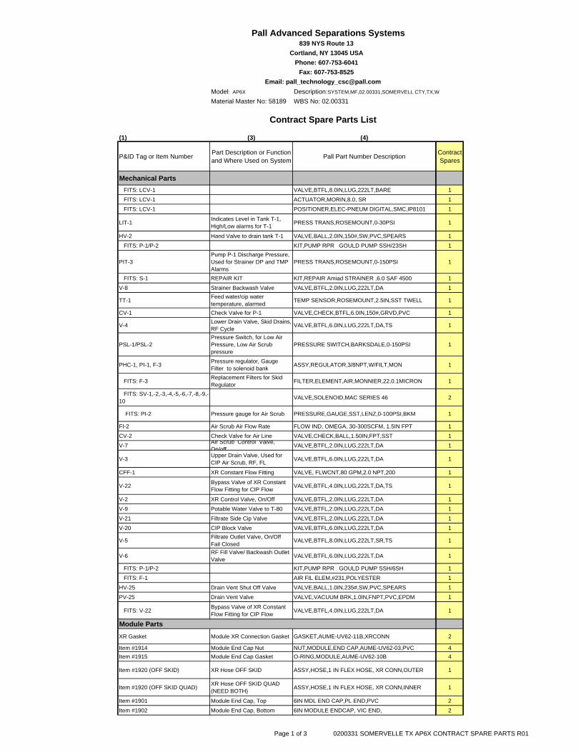
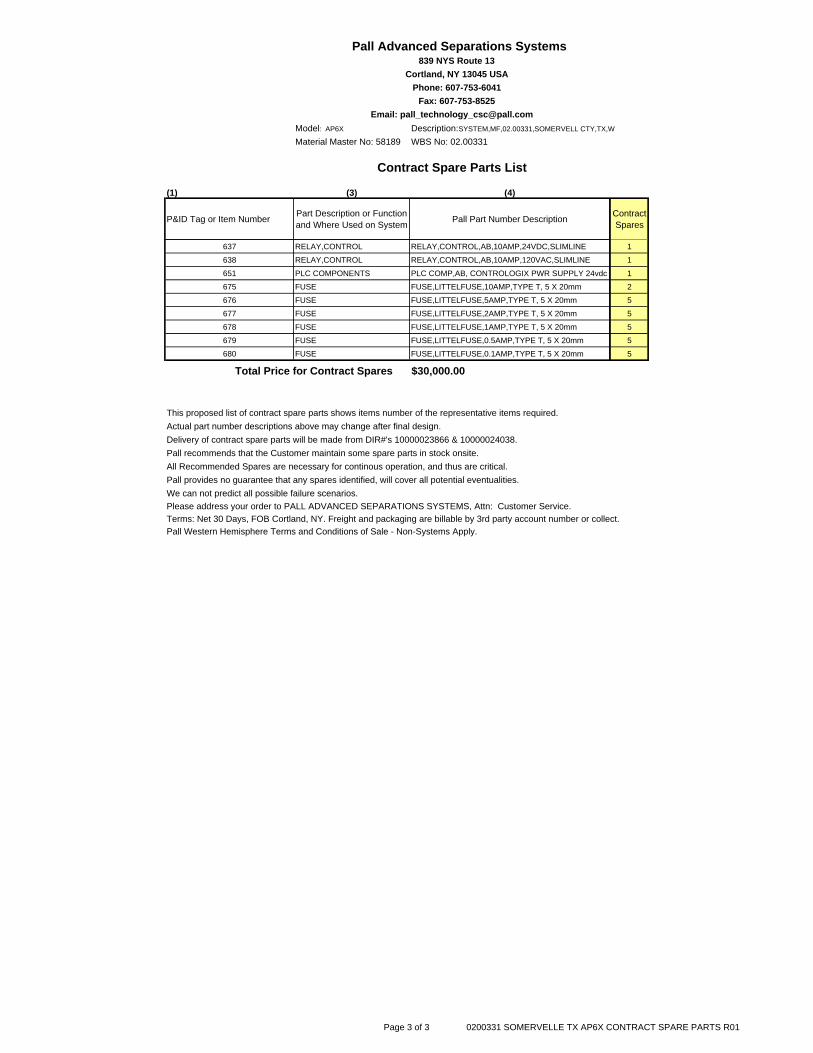
Model: AP6X Description:SYSTEM,MF,02.00331,SOMERVELL CTY,TX,W
Material Master No: 58189 WBS No: 02.00331
(1) (3) (4)
P&ID Tag or Item Number Part Description or Function and Where Used on System Pall Part Number Description Contract
Spares
Mechanical Parts FITS: LCV-1 VALVE,BTFL,8.0IN,LUG,222LT,BARE 1
FITS: LCV-1 ACTUATOR,MORIN,8.0, SR 1
FITS: LCV-1 POSITIONER,ELEC-PNEUM DIGITAL,SMC,IP8101 1
LIT-1 Indicates Level in Tank T-1, High/Low alarms for T-1 PRESS TRANS,ROSEMOUNT,0-30PSI 1
HV-2 Hand Valve to drain tank T-1 VALVE,BALL,2.0IN,150#,SW,PVC,SPEARS 1
FITS: P-1/P-2 KIT,PUMP RPR GOULD PUMP SSH/23SH 1
PIT-3Pump P-1 Discharge Pressure, Used for Strainer DP and TMP Alarms
PRESS TRANS,ROSEMOUNT,0-150PSI 1
FITS: S-1 REPAIR KIT KIT,REPAIR Amiad STRAINER ,6.0 SAF 4500 1
V-8 Strainer Backwash Valve VALVE,BTFL,2.0IN,LUG,222LT,DA 1
TT-1 Feed water/cip water temperature, alarmed TEMP SENSOR,ROSEMOUNT,2.5IN,SST TWELL 1
CV-1 Check Valve for P-1 VALVE,CHECK,BTFL,6.0IN,150#,GRVD,PVC 1
V-4 Lower Drain Valve, Skid Drains, RF Cycle VALVE,BTFL,6.0IN,LUG,222LT,DA,TS 1
PSL-1/PSL-2Pressure Switch, for Low Air Pressure, Low Air Scrub pressure
PRESSURE SWITCH,BARKSDALE,0-150PSI 1
PHC-1, PI-1, F-3 Pressure regulator, Gauge Filter to solenoid bank ASSY,REGULATOR,3/8NPT,W/FILT,MON 1
FITS: F-3 Replacement Filters for Skid Regulator FILTER,ELEMENT,AIR,MONNIER,22,0.1MICRON 1
FITS: SV-1,-2,-3,-4,-5,-6,-7,-8,-9,-10 VALVE,SOLENOID,MAC SERIES 46 2
FITS: PI-2 Pressure gauge for Air Scrub PRESSURE,GAUGE,SST,LENZ,0-100PSI,BKM 1
FI-2 Air Scrub Air Flow Rate FLOW IND, OMEGA, 30-300SCFM, 1.5IN FPT 1
CV-2 Check Valve for Air Line VALVE,CHECK,BALL,1.50IN,FPT,SST 1
V-7 Air Scrub Control Valve, On/off VALVE,BTFL,2.0IN,LUG,222LT,DA 1
V-3 Upper Drain Valve, Used for CIP Air Scrub, RF, FL VALVE,BTFL,6.0IN,LUG,222LT,DA 1
CFF-1 XR Constant Flow Fitting VALVE, FLWCNT,80 GPM,2.0 NPT,200 1
V-22 Bypass Valve of XR Constant Flow Fitting for CIP Flow VALVE,BTFL,4.0IN,LUG,222LT,DA,TS 1
V-2 XR Control Valve, On/Off VALVE,BTFL,2.0IN,LUG,222LT,DA 1
V-9 Potable Water Valve to T-80 VALVE,BTFL,2.0IN,LUG,222LT,DA 1
V-21 Filtrate Side Cip Valve VALVE,BTFL,2.0IN,LUG,222LT,DA 1
V-20 CIP Block Valve VALVE,BTFL,6.0IN,LUG,222LT,DA 1
V-5 Filtrate Outlet Valve, On/Off Fail Closed VALVE,BTFL,8.0IN,LUG,222LT,SR,TS 1
V-6 RF Fill Valve/ Backwash Outlet Valve VALVE,BTFL,6.0IN,LUG,222LT,DA 1
FITS: P-1/P-2 KIT,PUMP RPR GOULD PUMP SSH/6SH 1
FITS: F-1 AIR FIL ELEM,#231,POLYESTER 1
HV-25 Drain Vent Shut Off Valve VALVE,BALL,1.0IN,235#,SW,PVC,SPEARS 1
PV-25 Drain Vent Valve VALVE,VACUUM BRK,1.0IN,FNPT,PVC,EPDM 1
FITS: V-22 Bypass Valve of XR Constant Flow Fitting for CIP Flow VALVE,BTFL,4.0IN,LUG,222LT,DA 1
Module PartsXR Gasket Module XR Connection Gasket GASKET,AUME-UV62-11B,XRCONN 2
Item #1914 Module End Cap Nut NUT,MODULE,END CAP,AUME-UV62-03,PVC 4Item #1915 Module End Cap Gasket O-RING,MODULE,AUME-UV62-10B 4
Item #1920 (OFF SKID) XR Hose OFF SKID ASSY,HOSE,1 IN FLEX HOSE, XR CONN,OUTER 1
Item #1920 (OFF SKID QUAD) XR Hose OFF SKID QUAD (NEED BOTH) ASSY,HOSE,1 IN FLEX HOSE, XR CONN,INNER 1
Item #1901 Module End Cap, Top 6IN MDL END CAP,PL END,PVC 2
Item #1902 Module End Cap, Bottom 6IN MODULE ENDCAP, VIC END, 2
Pall Advanced Separations Systems 839 NYS Route 13
Cortland, NY 13045 USA Phone: 607-753-6041
Fax: 607-753-8525Email: [email protected]
Contract Spare Parts List
Page 1 of 3 0200331 SOMERVELLE TX AP6X CONTRACT SPARE PARTS R01
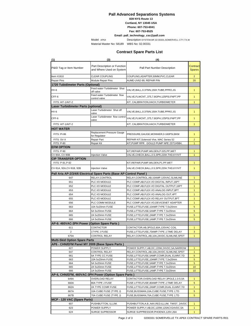
Model: AP6X Description:SYSTEM,MF,02.00331,SOMERVELL CTY,TX,W
Material Master No: 58189 WBS No: 02.00331
(1) (3) (4)
P&ID Tag or Item Number Part Description or Function and Where Used on System Pall Part Number Description Contract
Spares
Pall Advanced Separations Systems 839 NYS Route 13
Cortland, NY 13045 USA Phone: 607-753-6041
Fax: 607-753-8525Email: [email protected]
Contract Spare Parts List
Item #1910 CLEAR COUPLING COUPLING,ADAPTER,50MM,PVC,CLEAR 2
Repair Pins Module Repair Pins AUME-UV62-99, REPAIR PIN 20
1720 Tubidimeter Parts (Optional)HV-6 Feed water Turbidimeter Shut
off valve VALVE,BALL,0.375IN,150#,TUBE,PPRO,JG 1
CFF-6 Feed water Turbidimeter flow control valve VALVE,FLWCNT,.375,7.8GPH,125PSI,FNPT,PP 1
FITS: AIT-1/AIT-2 KIT, CALIBRATION,HACH,TURBIDIMETER 1
Laser Turbidimeter Parts (optional)HV-6 Laser Turbidimeter Shut off
valve VALVE,BALL,0.375IN,150#,TUBE,PPRO,JG 1
CFF-6 Laser Turbidimeter flow control valve VALVE,FLWCNT,.375,7.8GPH,125PSI,FNPT,PP 1
FITS: AIT-1/AIT-2 KIT, CALIBRATION,HACH,TURBIDIMETER 1
HOT WATER FITS: PI-86 Replacement Pressure Gauge
for Regulator PRESSURE,GAUGE,MONNIER,0-160PSI,BKM 1
FITS: SV-X Repair Part REPAIR KIT,Solenoid Vlve, MAC Series 52 2 FITS: P-80 Repair Kit KIT,PUMP RPR GOULD PUMP NPE 2ST1H5B4, 1EFM OPTION FITS: P-90 KIT,REPAIR,PUMP,WILDEN,P.025,PP,WET 1CV-90A, CV-90B Injection Valve VALVE,CHECK,BALL,0.5,SPR,220#,THD,KY/VIT 1CIP TRANSFER OPTION FITS: P-91,P-92 KIT,REPAIR,PUMP,WILDEN,P1,PP,WET 1
CV-91A, 92A,CV-91B, 92B Injection Valve VALVE,CHECK,BALL,0.5,SPR,220#,THD,KY/VIT 1
Pall Aria AP-2/3/4/6 Electrical Spare Parts (Base AP Control Panel )647 RELAY,CONTROL RELAY,CONTROL,AB,10AMP,120VAC,SLIMLINE 1
651 PLC I/O MODULE PLC COMP,AB,FLEX I/O DIGITAL INPUT,16PT 1
652 PLC I/O MODULE PLC COMP,AB,FLEX I/O DIGITAL OUTPUT,16PT 1
653 PLC I/O MODULE PLC COMP,AB,FLEX I/O ANALOG INPUT,8PT 1
654 PLC I/O MODULE PLC COMP,AB,FLEX I/O ANALOG OUT,4PT 1
655 PLC I/O MODULE PLC COMP,AB,FLEX I/O RELAY OUTPUT,8PT 1
656 PLC COMM MODULE PLC COMP,AB,FLEX I/O,DEVICENET ADAPTER 1
663 10A 5x20mm FUSE FUSE,LITTELFUSE,10AMP,TYPE T,5x20mm 5
664 5A 5x20mm FUSE FUSE,LITTELFUSE,5AMP,TYPE T,5x20mm 5
665 2A 5x20mm FUSE FUSE,LITTELFUSE,2AMP,TYPE T,5x20mm 5
666 1A 5x20mm FUSE FUSE,LITTELFUSE,1AMP,TYPE T,5x20mm 5
AP-6: 460VAC-3PH Power (Option Spare Parts )611 CONTACTOR CONTACTOR,AB,3POLE,60A,120VAC COIL 1
2 1TYPE J FUSE FUSE,LITTELFUSE,70AMP,TYPE J,TIME DELAY 3
675A CONTROL RELAY RELAY,CONTROL,AB,10A,24VDC,SLIMLINE,SPDT 1
Multi-Skid Option Spare PartsAP6 - CHN/EFM Panel MY 2009 (Base Spare Parts )
627 POWER SUPPLY POWER SUPPLY,AB,DC,120W,24VDC,5A,NARROW 1647 CONTROL RELAY RELAY,CONTROL,AB,10A,24VDC,SLIMLINE,SPDT 1661 5A TYPE CC FUSE FUSE,LITTELFUSE,5AMP,CCMR,DUAL ELMNT,TD 5663 10A 5x20mm FUSE FUSE,LITTELFUSE,10AMP,TYPE T,5x20mm 5664 5A 5x20mm FUSE FUSE,LITTELFUSE,5AMP,TYPE T,5x20mm 5665 2A 5x20mm FUSE FUSE,LITTELFUSE,2AMP,TYPE T,5x20mm 10666 1A 5x20mm FUSE FUSE,LITTELFUSE,1AMP,TYPE T,5x20mm 10
AP-6, CHN/EFM, 460VAC-3PH Power (Option Spare Parts )649A OVERLOAD RELAY CONTACTOR,OVERLOAD RELAY,3POLE,1.0-5.0A 1
660A 80A TYPE J FUSE FUSE.LITTELFUSE,80AMP,TYPE J,TIME DELAY 5
662A 2A TYPE CCMR FUSE FUSE,LITTELFUSE,2AMP,CCMR,DUAL ELMNT,TD 1
667A 10A CUBE FUSE (TYPE J) FUSE,BUSSMAN,10A,CUBE FUSE,TYPE J,TD 5
667B 70A CUBE FUSE (TYPE J) FUSE,BUSSMAN,70A,CUBE FUSE,TYPE J,TD 5
MCP - 120 VAC (Spare Parts)607 PUSHBUTTON, ILLUM. PUSHBUTTON,A.B.,N4X,RED,ILLUM, TWIST, 24VDC 1
623 POWER SUPPLY POWER SUPPLY,AB,DC,120W,120ACX24VDC,5A 1
624 SURGE SUPRESSOR SURGE SUPPRESSOR,PHOENIX,120V,26A 1
Page 2 of 3 0200331 SOMERVELLE TX AP6X CONTRACT SPARE PARTS R01
Model: AP6X Description:SYSTEM,MF,02.00331,SOMERVELL CTY,TX,W
Material Master No: 58189 WBS No: 02.00331
(1) (3) (4)
P&ID Tag or Item Number Part Description or Function and Where Used on System Pall Part Number Description Contract
Spares
Pall Advanced Separations Systems 839 NYS Route 13
Cortland, NY 13045 USA Phone: 607-753-6041
Fax: 607-753-8525Email: [email protected]
Contract Spare Parts List
637 RELAY,CONTROL RELAY,CONTROL,AB,10AMP,24VDC,SLIMLINE 1
638 RELAY,CONTROL RELAY,CONTROL,AB,10AMP,120VAC,SLIMLINE 1
651 PLC COMPONENTS PLC COMP,AB, CONTROLOGIX PWR SUPPLY 24vdc 1
675 FUSE FUSE,LITTELFUSE,10AMP,TYPE T, 5 X 20mm 2
676 FUSE FUSE,LITTELFUSE,5AMP,TYPE T, 5 X 20mm 5
677 FUSE FUSE,LITTELFUSE,2AMP,TYPE T, 5 X 20mm 5
678 FUSE FUSE,LITTELFUSE,1AMP,TYPE T, 5 X 20mm 5
679 FUSE FUSE,LITTELFUSE,0.5AMP,TYPE T, 5 X 20mm 5
680 FUSE FUSE,LITTELFUSE,0.1AMP,TYPE T, 5 X 20mm 5
Total Price for Contract Spares $30,000.00
This proposed list of contract spare parts shows items number of the representative items required.Actual part number descriptions above may change after final design.Delivery of contract spare parts will be made from DIR#'s 10000023866 & 10000024038.Pall recommends that the Customer maintain some spare parts in stock onsite.All Recommended Spares are necessary for continous operation, and thus are critical. Pall provides no guarantee that any spares identified, will cover all potential eventualities. We can not predict all possible failure scenarios. Please address your order to PALL ADVANCED SEPARATIONS SYSTEMS, Attn: Customer Service.Terms: Net 30 Days, FOB Cortland, NY. Freight and packaging are billable by 3rd party account number or collect.Pall Western Hemisphere Terms and Conditions of Sale - Non-Systems Apply.
Page 3 of 3 0200331 SOMERVELLE TX AP6X CONTRACT SPARE PARTS R01
Pilot Operated Solenoid Control Valve 15114-1 SOM08416B – Somervell County WTP
15114 PILOT OPERATED SOLENOID CONTROL VALVE
1.00 GENERAL
1.01 WORK INCLUDED
A. Furnish labor, materials, equipment and incidentals necessary to install and test with all appurtenances and accessories to install pilot operated solenoid control valves on discharge piping for the pumps at the High Service Pump Station.
B. The equipment furnished under this specification shall be suitable for use in a potable municipal water system.
1.02 QUALITY ASSURANCE
A. EXPERIENCE REQUIREMENTS
Valves shall be the product of a manufacturer who has a least 10 years experience of successful experience in the design, manufacture and application of pilot operated solenoid control valves used in water service and pump control.
B. ASSEMBLY
The valve, strainers, piping, opening and closing speed control valves and other appurtenances shall be completely assembled, wired and tested at the factory. The valve seats shall be adjusted at the factory for correct seating.
C. MANUFACTURER'S REPRESENTATIVE
The valve manufacturer shall furnish the services of a competent service technician for the duration of time necessary to assist in the installation, adjustment and start-up operation, and field acceptance testing. The technician shall instruct the Owner's personnel in the proper care, maintenance, adjustment and operation of the equipment and shall issue a written certification that the equipment has been properly installed.
D. ACCEPTABLE MANUFACTURERS
Acceptable valve manufacturers include the following: 1. CLA-VAL Company- Model 60-41BCSYKC, as outlined in the valve schedule. 2. Engineer Approved Equal.
1.03 SUBMITTALS
A. Submittals shall be provided in accordance with Section 01300, SUBMITTALS and shall include:
1. Shop drawings 2. Operation and maintenance manuals
1.04 STANDARDS
A. The applicable provisions of the following standards shall apply as if written here in their entirety.
ASTM A48 "Standard Specification for Gray Iron Castings" ASTM B61 ASTM B62

Pilot Operated Solenoid Control Valve 15114-2 SOM08416B – Somervell County WTP
AWWA C-550 "Standard Specification for Protective Interior Coatings for Valves and Hydrants" ANSI American National Standards Institute NEMA National Electric Manufacturers Association
B. All pilot operated solenoid control for potable water systems shall conform to American National Standards Institute/National Science Foundation (ANSI/NSF) Standard 61 and must be certified by an organization accredited by ANSI.
1.05 GUARANTEES
A. Vendor shall warrant the equipment furnished under this specification for a period of two (2) year against defects in materials, workmanship and operational failure.
B. In the event of failure of any part or parts of the equipment during the first year of operation, the Vendor shall furnish, deliver and install the defective part or parts at no additional expense to the Owner.
C. The two years of service shall be interpreted as the 24-month period following installation, adjusting, acceptance testing and start of actual operation of the equipment, or 30 months following delivery of the equipment, whichever comes first.
2.00 PRODUCTS
2.01 MANUFACTURED PRODUCTS
A. GENERAL
1. The valves shall meet NSF, TWDB, and AWWA requirements for potable water service. 2. The valve body shall be a globe pattern value. It shall incorporate in its design two
operating chambers, sealed from one another by a flexible diaphragm. Valve bodies and covers shall be cast and machined in North America.
3. Valves shall be diaphragm actuated, hydraulic operated, pilot controlled type, and designed to control starting and stopping surges from the pump. The diaphragm assembly shall be the only moving part and shall be fully guided by bearings in the valve cover and lower operating unit.
4. Valves shall be tight closing, with BUNA-N-Synthetic rubber discs. The discs shall be field replaceable and the valves shall be serviceable inline by removing the cover. Valves shall be drip tight at rated pressures with flow in one direction and shall be satisfactory for applications involving valve operation after long periods of inactivity.
5. Valve body interior and exterior surfaces shall be epoxy resin coated and shall be suitable for high velocity service. The coating shall be applied by the fusion bond method and will be a minimum thickness of 8 mills when complete.
6. Valves shall be equipped with opening and closing speed control by means of an exterior flow rate control valve.
7. The pilot shall be a three way pilot used for on/off service and include a dual supply system to insure the highest system pressure for pilot control operation. The valve shall be opened or closed based on an electrical signal received from contacts located at the pump motor. The pilot system shall be furnished to operate at 120 volts, 60 Hz A.C.
8. Provide piping to convey water expelled from the valve bonnet to floor drains, sumps or as directed by the Owner.
Pilot Operated Solenoid Control Valve 15114-3 SOM08416B – Somervell County WTP
B. OPERATION
1. The valve shall close fully when the electrical signal is removed from the three way solenoid or four way solenoid pilot control. A three way solenoid shall be used on the 12” or larger valves. Valves shall not slam shut on power failure.
2. A three-way solenoid pilot control switch is to be connected to the termination cabinet through which the operator at the WTP may manually or automatically control the valve.
C. SOLENOID CONTROL VALVE
1. Pressure Class -- 150 Pound Flanged – Rated to 250 psi 2. Main valve body & cover – ASTM A536 3. Main valve trim -- Brass QQ-B-6265
-- Bronze ASTM B61 4. Pilot control system -- Cast Brass ASTM B62
with 303 Stainless Steel trim 5. Rubber parts -- Buna-N-Synthetic Rubber 6. Tubing & control piping - Stainless Steel Piping & Fittings
2.02 LIMIT SWITCHES FOR MOTOR CONTROL
A. Limit switches shall be dry contacts and shall be independently adjustable at the open and closed limit. Auxiliary limit switches shall have isolated Form A or B contacts rated for 10 amps at 120 VAC.
B. Two (2) limit switches are required. Limit switches shall be furnished for valve control, for remote and local OPEN and CLOSE indications, pump motor start permissive, valve failure limit switch (95%) and pump motor start command (5%).
C. VALVE LIMIT SWITCH SETTINGS. The first switch must lock the relay between pump starter and motor when starting the pump so that the pump can run and not allow the pump to shut off until the pump is called to go to the off condition. The second limit switch indicates valve fully open so that the pump can continue to run. A timer dictates the time to allow for valve fully open and make the top limit switch so that the pump can continue to run.
3.00 EXECUTION
3.01 INSTALLATION Install the valve in the pump discharge piping with the valve diaphragm shaft in the vertical position. Make all connections between the valve and the valve pilot. Installation of the valve shall be in accordance with the valve manufacturer's recommendations.
3.02 FIELD QUALITY CONTROL Upon completion of the installation of the equipment, an acceptance test to verify the satisfactory operation of the valve shall be performed. The test shall be conducted in a manner, approved by and in the presence of the Engineer. The valve manufacturer’s representative shall be present during the valve acceptance test. The unit must perform in a manner acceptable to the Engineer before final acceptance will be made by the Owner.
3.03 CLEAN AND ADJUST All adjustments will be performed in accordance with the valve manufacturer's instructions.

Pilot Operated Solenoid Control Valve 15114-4 SOM08416B – Somervell County WTP
3.04 SCHEDULES The control valve furnished under this specification shall meet the following requirements:
Number Required
Size (inches)
Pressure Class Location Base Bid/Alternate
Bid 1 8 150 psi High Service
Pump Station Base Bid
2 10 150 psi High Service Pump Station
Base Bid
END OF SECTION
15136 MISCELLANEOUS VALVES 1.00 GENERAL 1.01 WORK INCLUDED
Furnish labor, materials, equipment and incidental necessary to install miscellaneous valves. 1.02 SUBMITTALS
Submittals shall be in accordance with Section 01300, SUBMITTALS and shall include:
1. Shop drawings 2. Operation and Maintenance Manuals
2.00 PRODUCTS 2.01 MANUFACTURED PRODUCTS
A. PVC BALL VALVES: PVC Ball Valves shall be furnished for chlorine vacuum and solution lines, alum tanks, polymer tanks, alum pumps, and polymer pumps and as otherwise indicated. Valves shall be true union, of Type 1 PVC, with PTFE seats, Viton "O" rings and with socket end connections. Valves shall be Chemtrol TU Series Ball Valves, GF Plastic Systems, Inc. Type 340, or approved equal.
B. CORPORATION STOPS: Corporation stops shall be bronze with tapered plug and flat key
operator. Unless otherwise indicated, stops shall be equal to Mueller H-10046 with iron pipe thread on inlet and outlet, of the size indicated.
C. HOSE FAUCET: Hose faucet shall be bronze sediment faucet with 1/2" pipe thread and
standard garden hose thread outlet with brass tee handle as manufactured by Woodford Model Y2, Mueller, or approved equal.
D. GLOBE VALVES: Globe Valves, where indicated shall be Crane No. 351 with American
Standard Class 125 flanges. Globe valves for screwed piping shall be equal to Crane No. 1.
E. CHLORINE SOLUTION VALVES: Valves for pressurized chlorine shall be as specified in Section 11242, LIQUID CHEMICAL FEED SYSTEM.
F. AMMONIA SOLUTION VALVES: Valves for the ammonia feed system shall be as specified
in Section 11242, LIQUID CHMICAL FEED SYSTEM.
G. PRESSURE AND VACUUM RELIEF VALVES: Pressure and vacuum relief valves for installation on anhydrous ammonia storage tanks shall be Varec Series 482 or Groth Equipment Corporation Model 1200. Valves shall have cast steel body, 316 Stainless Steel trim and neoprene seat insert.
H. DRAIN (MUD) VALVES: Drain valves shall be non-rising stem mud valves, with cast iron
body; bronze stem, stem nut, disc ring, and seat ring; and stainless steel bolts and nuts. Valves shall be furnished with handwheels and shall be Clow F3075 or approved equal.
I. SHEAR GATES: Shear gates shall be double wedge type, with iron body and bronze
wedges. Wedges shall be bolted to the shear gate frame. Gates shall be furnished with a pull rod, lifting handle, and catch. Gates shall be M&H style 44 or approved equal.
Miscellaneous Valves 15136-1 SOM08416B – Somervell County WTP
2.02 CHECK VALVES FOR CHEMICAL SOLUTION
A. Check valves in chlorine, and liquid ammonium sulfate solution lines and other locations indicated shall be Cabot Chemtrol BC Series or approved equal, of Type 1 PVC and Viton seats. Ends shall be Class 125 flanges, or sockets as indicated or required.
2.03 FLAP VALVES
A. Flap valves shall be circular flange framed, with machined back flange for attachment to a flanged wall thimble. Body and flap shall be cast iron, ASTM A-126-B. Resilient seat shall be neoprene or Buna-N bonded in a groove machined in the body. Hinge arms shall be high-tensile bronze, ASTM B-584-CA865 with two pivot points, an adjustable lower pivot with limited rotation and a threaded upper hinge post to adjust flap valve sensitivity. A lubrication fitting shall be supplied for each pivot. Hinge pins shall be silicon bronze, ASTM B-98-CA655 or Type 304 Stainless Steel.
B. Flap valve shall be designed to open when differential head across the flap is 0.3' or less.
C. Flap valve shall be Rodney Hunt Series FV-AC, Waterman Equal Model, or equal.
2.04 BACKFLOW PREVENTERS
A. Provide reduced pressure principle backflow preventers meeting requirements of ANSI/ASSE 1013. Backflow preventers shall be rated at 150 psi working pressure, and shall comply with AWWA Standard C506.
B. Units 2-1/2" and larger shall consist of two independently acting check valves together with
an automatically operating pressure relief valve, two gate valves, and four test cocks, bronze or iron body with bronze internal parts. Acceptable manufacturers and models: Cla-Val Co., RP-1 (2" & larger); Watts, 909; Hersey, 6CM, Wilkins, 975 and Febco, 825.
C. Units 2" and smaller shall consist of two independently acting check valves together with an
automatically operating pressure relief valve, two ball valves, strainer, and four test cocks, bronze or iron body with bronze internal parts. Acceptable manufacturers and models are Cla-Val Co., RP-2 (1-1/2" & smaller); Watts, 009; Wilkins, 975XL, Hersey, FRP-II, Febco, 825Y and Wilkins, 575.
D. Provide Watts, TK-9-A test kit consisting of gauge test valves, hoses, adaptors, securing
strap, instruction guide and lightweight case. 2.05 SOLENOID VALVES
Solenoid valve shall be a two position valve. Solenoid enclosure shall be water tight. The construction of the valve shall be brass with FPM seals. The valve shall be normally open, energize closed. Control voltage shall be coordinated with the control manufacturer. Valve shall be ASCO or approved equal.
2.06 AIR RELEASE VALVES
A. Each air release valve shall have a cast iron body, bronze, or stainless steel trim and stainless steel float. Float shall be baffled to prevent air from blowing valve closed until air is exhausted.
B. Valve inlet shall be N.P.T. for 2” and smaller valves. Valve inlet shall be ANSI flange for 3” and larger valves. Flange rating shall equal or exceed the maximum working pressure.
Miscellaneous Valves 15136-2 SOM08416B – Somervell County WTP
C. Air release valves shall be designed to automatically release accumulated air pockets within the pipeline while in operation and under pressure. Air release valves shall be APCO Model 200, Val-Matic Model 38, or Crispin Model P.
2.07 BALL VALVES W/ ELECTRIC ACTUATORS
Modulating ball valves shall be 2”, 3” and 4” FlowTek V-port ball valve with Bray electric actuator or approved equal. Ball valves shall be ASME Class 150 2-Pc RF Full Port Flanged End V-Control Ball Valve with ASTM A216 GR WCB Black Phosphate Coated Body per ASME B16.10 Long Pattern Dimensions, ASTM A351 Gr CF8M 30-Degree V-Port Ball, Tek-Fil Seats, Smart Stem design consisting of Live Loaded Packing Arrangement with RPTFE Stem Packing and SS301 Belleville Washers, 50/50 Stem Thrust Washer, and PEEK Protector.
The electric actuator shall be compact and low–profile to greatly reduce space requirements. The actuator shall feature ease of access to field wiring and adjustment. The actuator shall be built to withstand line vibration and shock without failure.
A. MOTOR: A single phase permanent split-capacitor reversible motor with voltages of 120 VAC
50/60 Hz shall be standard. Motor insulation shall be Class F or better. The motor shall contain a built-in UL approved automatic reset thermal overload protector set at 275°F (135°C) embedded in motor windings. The duty cycle shall be 100% continuous duty.
B. SPUR GEAR TRAIN SYSTEM: The actuator shall have a self-locking gear train consisting of
a worm and worm gear output drive mechanism. The spur gear train shall have precision cut multi-staged gears which will withstand locked rotor conditions. The spur gear train shall be permanently lubricated at the factory. The gear train shall drive a chrome-moly steel worm which drives the composite aluminum bronze segmented worm gear / output shaft.
C. WIRING: Actuator switches shall be pre-wired to a terminal block for ease of access and all
internal wiring shall range from 12-22 AWG.
D. SWITCHES:
a. All travel switches shall be Single Pole, Double Throw, Form C type, 10A at 125VAC, 1/2 A at 125 VDC, UL listed and CSA approved. Travel Limit switches shall limit actuator in both the open and closed position of valve travel. Limit switches shall be dry contacts and shall be independently adjustable at the open and closed limit.
b. Four (4) limit switches shall be required for each valve/electric actuator. Limit switches shall be furnished for remote and local Full OPEN and Full CLOSE indications.
E. CAMS: Cams for each travel limit switch shall be infinitely adjustable by finger touch or screw driver, as provided by Bray’s patented design.
F. CONDUIT ENTRIES: All units shall have 2 conduit entries. Conduit entries for models 003
and 005 shall be either 1/2" NPT or M 20. Conduit entries for models 008 – 065 shall be either 3/4" NPT or M 25.
G. MECHANICAL TRAVEL STOPS: Mechanical stainless steel travel stops shall be located
outside the actuator for ease of adjustment and contain stainless steel lock nuts to hold the travel stops in place. O-rings provide waterproof seals. The travel stops shall limit the actuator movement to specific degrees of rotation.
Miscellaneous Valves 15136-3 SOM08416B – Somervell County WTP
H. MANUAL OVERRIDE: All units shall be equipped with an aluminum manual override handwheel to rotate the valve without electrical power. The override assembly shall ensure positive and fast manual operation without the use of extra tools or levers.
I. EMERGENCY SHUT-OFF: An automatic power cutout switch shall be provided to cut power
to the motor when actuator handwheel is engaged for manual operation. This switch shall function as a safety emergency shutdown device.
J. ENCLOSURE: The die-cast aluminum enclosure shall be certified to UL, CSA & CE
waterproof standards (NEMA 4, 4X, IP 65). Cover shall be polyester powder coated for exceptional corrosion, wear, impact and UV resistance. The enclosure shall have captive cover bolts, therefore preventing time consuming problems due to lost or misplaced bolts.
K. VALVE STATUS DISPLAY: The actuator shall have a highly visible clear polycarbonate
display prominently labeled and color coded to indicate valve position throughout the full range of travel.
L. TEMPERATURE RATING: Actuators shall be designed for temperature ranges of -40°F (-40°C) to +150°F (65°C).
M. HEATER: with self-regulating temperature control to prevent condensation buildup. The
heater shall be pre-wired to the terminal block. Rated output is 15 W at 120 or 220 VAC. N. SERVO: A microprocessor controlled Servo shall be available for precise modulating control
of valve position in response to an analog input signal. The Servo shall have an analog output signal proportional to actual valve position as standard. This analog signal shall be 4-20mADC. The Servo shall have a specially engaged potentiometer gear which prevents damage due to over rotation. The Servo shall have voltage spike protection on all Input terminals. Adjustments shall be provided for both open and closed Speed Control of the actuator. Input Signals: 4-20 mADC into 250 Ohm, 0-10 VDC, 0-5 VDC, 135 Ohm or greater potentiometer. 10k Ohm Potentiometer shall be used for internal feedback.
O. CONTROL STATION: for manual local electrical operation of the actuator. The Control
Station shall flush mount to the actuator and feature a local / off / remote control switch, an open–stop–close switch, and two lights which locally indicate open and closed valve position. The enclosure shall be aluminum and waterproof (NEMA 4, 4X, IP 65). Provide a contact that shall close when the local/ off/ remote switch is in the remote position. The contact shall be Form C type, 10A at 125VAC, 1/2 A at 125 VDC, UL listed and CSA approved.
2.08 PRESSURE REDUCING VALVES
A. The Contractor shall furnish and install 4" pressure reducing valve in the potable water line in the high service pump station as shown on the Plans and specified herein. The pressure reducing valve shall be a hydraulically operated, single pilot, globe pattern valve. The valve body shall be cast iron. The pilot valve, piston, liner, seat, and crown shall be bronze. The valve shall receive a 12 mil epoxy coating for corrosion protection.
B. The pressure reducing valve shall be suitable for a 150 psi working pressure, 75 psi surge
pressure, and shall be capable of reducing a maximum 130 psi inlet pressure to a discharge pressure of 65 psi. The diaphragm operated pilot valve shall be easily adjustable providing a minimum discharge pressure range of 50 psi.
C. Valve shall come complete with two glycerin filled pressure gauges with snubber fittings, one
to monitor upstream pressure in psi, and one to monitor downstream pressure in psi.
Miscellaneous Valves 15136-4 SOM08416B – Somervell County WTP
Miscellaneous Valves 15136-5 SOM08416B – Somervell County WTP
D. Pressure reducing valve at the high service pump station shall be GA Industries Model 4900-D, Clayton (equal model), or approved equal. All other pressure reducing valves shall be GA Industries Model 4500-D or approved equal.
2.09 CHEMICAL INJECTION AND SAMPLE PUMP CONNECTIONS
Materials of construction for chemical injection connections shall be compatible with the chemical solution and shall be capable of withstanding maximum pump discharge line pressure, water main pressure and flow rate. The water main connection shall be a Heavy Duty Brass Corp. Stop or Stainless Steel Ball Valve. Thread connections shall be NPT or AWWA inlet and capable of withstanding maximum water main pressure. Corp. stop must include an acceptable safety device to prevent accidental withdrawal of solution tube while under maximum pressure and/or surge conditions. A ball check valve shall be included to prevent backpressure from the main from entering the chemical feed system. A stainless steel safety chain shall be included to prevent withdrawal of solution tube past Corp. stop. Safety chain length shall be preset by manufacturer for closure of the Corp. stop before withdrawal of solution tube. Operator shall be able to safely withdraw or insert solution tube into center of main while under pressure and without having to shut down the main. Chemical injector assembly shall be Saf-T-Flo, Severn Trent or approved equal.
3.00 EXECUTION 3.01 INSTALLATION
Carefully handle and install valves in a manner that prevents damage to any part of the valves. Install valves in accordance with the Manufacturer's instructions.
END OF SECTION