Part No. 02110SL (Rev. D) Service Manual Workman R 1100/1110/2100/2110 Preface The purpose of this publication is to provide the service technician with information for troubleshooting, testing, and repair of major systems and components on the Workman 1100, 1110, 2100, and 2110. REFER TO THE OPERATORS MANUAL FOR OPER- ATING, MAINTENANCE, AND ADJUSTMENT IN- STRUCTIONS. Space is provided in Chapter 2 of this book to insert the Operators Manuals and Parts Cata- logs for your machine. Replacement Operators Manu- als are available on the Internet at www.toro.com or by sending complete Model and Serial Number to: The Toro Company Attn. Technical Publications 8111 Lyndale Avenue South Bloomington, MN 554201196 The Toro Company reserves the right to change product specifications or this publication without notice. This safety symbol means DANGER, WARNING, or CAUTION, PERSONAL SAFETY INSTRUC- TION. When you see this symbol, carefully read the instructions that follow. Failure to obey the instructions may result in personal injury. Note: A Note will give general information about the correct operation, maintenance, service, testing, or re- pair of the machine. IMPORTANT: The IMPORTANT notice will give im- portant instructions which must be followed to pre- vent damage to systems or components on the machine. E The Toro Company 2002, 2004, 2005, 2006, 2007
Transcript
Part No. 02110SL (Rev. D)
Service Manual
Workman� 1100/1110/2100/2110
Preface
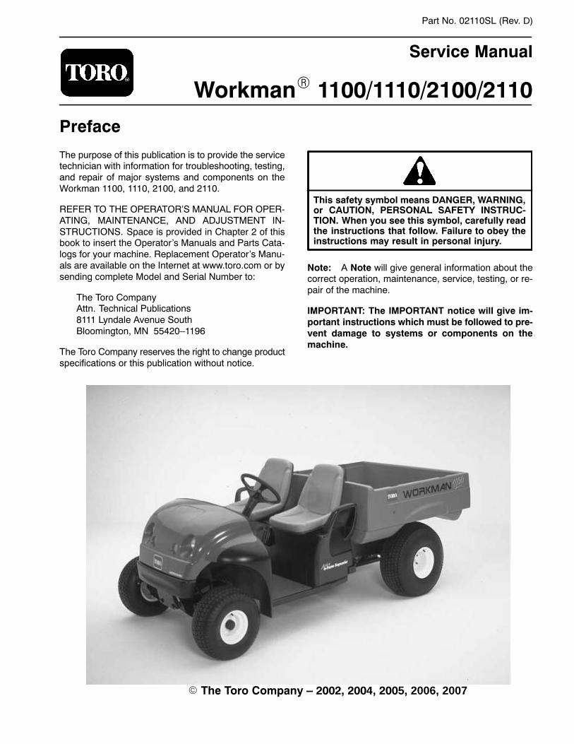
The purpose of this publication is to provide the servicetechnician with information for troubleshooting, testing,and repair of major systems and components on theWorkman 1100, 1110, 2100, and 2110.
REFER TO THE OPERATOR�S MANUAL FOR OPER-ATING, MAINTENANCE, AND ADJUSTMENT IN-STRUCTIONS. Space is provided in Chapter 2 of thisbook to insert the Operator�s Manuals and Parts Cata-logs for your machine. Replacement Operator�s Manu-als are available on the Internet at www.toro.com or bysending complete Model and Serial Number to:
The Toro CompanyAttn. Technical Publications8111 Lyndale Avenue SouthBloomington, MN 55420�1196
The Toro Company reserves the right to change productspecifications or this publication without notice.
This safety symbol means DANGER, WARNING,or CAUTION, PERSONAL SAFETY INSTRUC-TION. When you see this symbol, carefully readthe instructions that follow. Failure to obey theinstructions may result in personal injury.
Note: A Note will give general information about thecorrect operation, maintenance, service, testing, or re-pair of the machine.
IMPORTANT: The IMPORTANT notice will give im-portant instructions which must be followed to pre-vent damage to systems or components on themachine.
The Workman 1100/2100/2110 was tested and certifiedby TORO for compliance with the B71.4–1984 specifica-tions of the American National Standards Institute. Al-though hazard control and accident prevention partiallyare dependent upon the design and configuration of themachine, these factors are also dependent upon theawareness, concern, and proper training of the person-nel involved in the operation, transport, maintenance,and storage of the machine. Improper use or mainte-nance of the machine can result in injury or death.
Read and understand the contents of the Operator’sManual before starting and operating the machine. Be-come familiar with all controls and know how to stop itquickly. A replacement manual is available on the Inter-net at www.toro.com or by sending complete Model andSerial Number to:
The Toro CompanyAttn. Technical Publications8111 Lyndale Avenue SouthMinneapolis, Minnesota 55420–1196
The safety alert symbol meansCAUTION, WARNING or DANGER — “personal safety instruction”. Read
and understand the instruction because it has todo with safety. Failure to comply with the instruc-tion may result in personal injury.
WARNINGTo reduce the potential for injury or death, complywith the following safety instructions.
Supervisors, operators, and service persons should befamiliar with the following standards and publications(The material may be obtained from the addressesshown):
• Flammable and Combustible Liquids Code:ANSI/NFPA 30
• National Fire Protection Association:ANSI/NFPA #505; Powered Industrial TrucksADDRESS:
National Fire Prevention AssociationBarrymarch ParkQuincy, Massachusetts 02269 U.S.A.
• ANSI/ASME B56.8; Personal Burden CarriersADDRESS:
American National Standards Institute, Inc.1430 BroadwayNew York, New York 10018 U.S.A.
American National Standards Institute, Inc.1430 BroadwayNew York, New York 10018 U.S.A. ORUnderwriters Laboratories333 Pfingsten RoadNorthbrook, Illinois 60062 U.S.A.
WARNINGThe Workman is an off–highway vehicle only. It isnot designed, equipped, or manufactured for useon public streets, roads or highways.
Supervisor’s Responsibilities
1. Make sure operators are thoroughly trained and fa-miliar with the Operator’s Manual and all labels on thevehicle.
2. Be sure to establish your own special proceduresand work rules for unusual operating conditions (e.g.slopes too steep for vehicle operation).
Before Operating
1. Operate machine only after reading and understand-ing the contents of this manual.
2. Never allow children to operate the vehicle. Neverallow adults to operate it without proper instructions.
Only trained and authorized persons should operate thisvehicle. Make sure all operators are physically and men-tally capable of operating the vehicle. Anyone who oper-ates the vehicle should have a motor vehicle license.
Workman 1100/2100/2110 Page 1 – 3 Safety
3. This vehicle is designed to carry the operator andone passenger in the seat provided by the manufactur-er. Never carry more than one passenger on the vehicle.
4. Never operate vehicle when under the influence ofdrugs or alcohol.
5. Become familiar with the controls and know how tostop the engine quickly.
6. Keep all shields, safety devices, and decals in place.Repair or replace any shield, safety device, or decal if itis malfunctioning, illegible, or damaged before operat-ing the machine.
7. Always wear substantial shoes. Do not operate ma-chine while wearing sandals, tennis shoes or sneakers.Do not wear loose fitting clothing or jewelry which couldget caught in moving parts and cause personal injury.
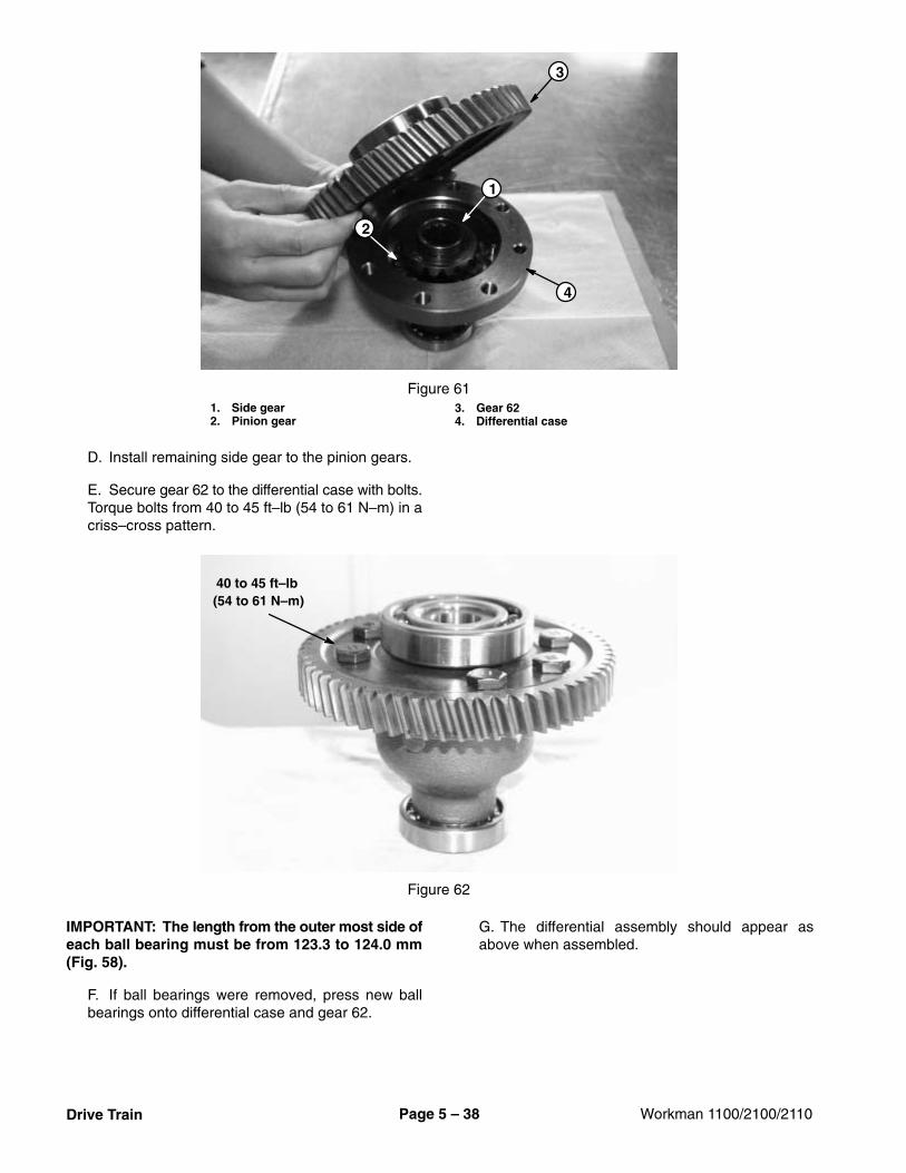
8. Wearing safety glasses, safety shoes, long pantsand a helmet is advisable, and may be required by somelocal safety and insurance regulations.
9. Keep everyone, especially children and pets, awayfrom the areas of operation.
10.Before operating the vehicle, always check vehicleand any attachments for damage. If something is wrong,stop using the vehicle. Make sure problem is cor-rected before the vehicle or attachment is operatedagain.
11.Since gasoline is highly flammable, handle it careful-ly.
A. Use an approved gasoline container.
B. Do not remove cap from the fuel tank when theengine is hot or running.
C. Do not smoke while handling gasoline.
D. Fill fuel tank outdoors to about one inch below thetop of tank (bottom of filler neck). Do not overfill.
which is odorless, colorless, poisonous,and deadly.
WHAT CAN HAPPEN• Carbon monoxide can cause death. It is
known by the State of California to causebirth defects.
HOW TO AVOID THE HAZARD• Do not run engine indoors or in an en–
closed area.
1. Operator and passenger should remain seatedwhenever the vehicle is in motion. Operator should keepboth hands on the steering wheel. Whenever possible,the passenger should use the hand holds provided.Keep arms and legs within the vehicle body at all times.Never carry passengers in the box or on any attach-ments. Remember your passenger may not be expect-ing you to brake or turn.
2. Never overload your vehicle. The name plate (lo-cated under the dash and on the center column) showsload limits for the vehicle. The load rating is for level sur-faces only. Never overload attachments or exceed thevehicle maximum gross vehicle weight (GVW).
3. Operating the vehicle demands attention. Failure tooperate the vehicle safely may result in an accident, tipover of vehicle, and/or serious injury or death. Drivecarefully. To prevent tipping or loss of control:
A. Use extreme caution, reduce speed, and main-tain a safe distance around sand traps, ditches,creeks, ramps, unfamiliar areas, or any areas thathave abrupt changes in ground conditions or eleva-tion.
WARNINGOperating the vehicle on a hill may causetipping or rolling of the vehicle, or the enginemay stall and you could lose headway on ahill. This could result in personal injury.• Do not exceed slopes greater than 12
degrees.• If the engine stalls or you lose headway on a
hill, never attempt to turn the vehiclearound.
• Never drive across a steep hill; always drivestraight up or down or go around the hill.
• Avoid turning on a hill.• Do not accelerate quickly or slam on the
brakes.• Reduce your load and the speed of the
vehicle.• Avoid stopping on hills, especially with a
load.
B. Use caution when operating vehicle on a slope.Normally travel straight up and down slopes. Reducespeed when making sharp turns or when turning onhillsides. Avoid turning on hillsides whenever pos-sible. If the engine stalls or you begin to lose head-way while climbing a hill, gradually apply the brakesand slowly back straight down the hill.
���
���
Workman 1100/2100/2110Page 1 – 4Safety
C. Watch for holes or other hidden hazards.
D. Use extra caution when operating the vehicle onwet surfaces, at higher speeds, or with a full load.Stopping distance will increase with a full load. Slowdown before starting up or down a hill.
E. When loading the box, distribute load evenly. Useextra caution if the load exceeds the dimensions ofthe box. Operate vehicle with extra caution whenhandling loads that cannot be centered. Keep loadsbalanced and secure to prevent them from shifting.
F. Avoid sudden stops and starts. Do not go from re-verse to forward, or forward to reverse, without firstcoming to a complete stop.
G. Do not attempt sharp turns, abrupt maneuvers, orother unsafe driving actions that may cause a loss ofvehicle control.
WARNING
The weight of the box may be heavy andcould crush hands or other body parts.• Keep hands and other body parts clear
when lowering the box.• Do not dump materials on bystanders.
H. When dumping, do not let anyone stand behindthe vehicle. Do not dump the load on anyone’s feet.Release tailgate latches from the side of the box, notfrom behind the box.
I. Only operate/drive vehicle when the cargo box isdown and latched.
J. Before backing up, look to the rear of the vehicle.Make sure no one is behind it. Back up slowly.
K. Watch out for traffic when near or crossing roads.Always yield the right of way to pedestrians and othervehicles. This vehicle is not designed for use onstreets or highways. Always signal your turns or stopearly enough so other persons know what you plan todo. Obey all traffic rules and regulations.
L. Never operate vehicle in or near an area wherethere is dust or fumes in the air which are explosive.The electrical and exhaust systems of the vehiclecan produce sparks capable of igniting explosivematerials.
M. Always watch out for and avoid low overhangssuch as tree limbs, door jambs, over head walkways,etc. Make sure there is enough room over head toeasily clear the vehicle and your head.
N. If ever unsure about safe operation, stop vehicleand ask your supervisor.
WARNING
Sudden changes in terrain may cause abruptsteering wheel movement, possibly resultingin hand and arm injuries.• Reduce your speed and the load when
operating on rough terrain and near curbs.• Grip the steering wheel loosely around the
perimeter. Keep your hands clear of thesteering wheel spokes.
O. When operating the vehicle over rough terrain ornear curbs, reduce your speed and grip the outsideof the steering wheel. Keep your hands and fingersaway from the steering wheel spokes.
4. Do not touch engine or muffler while the engine isrunning or soon after it has stopped. These componentsmay be hot enough to cause burns.
5. If the machine ever vibrates abnormally, stop imme-diately. Wait for all motion to stop. Inspect vehicle fordamage. Repair all damage before commencing opera-tion.
6. Before getting off the seat:
A. Stop movement of the machine.
B. Set parking brake.
C. Turn ignition key to OFF.
D. Remove key from ignition switch.
CAUTION
If vehicle is parked on an incline, chock wheelsafter getting off of the vehicle.
Workman 1100/2100/2110 Page 1 – 5 Safety
Maintenance and Service
1. Only qualified and authorized personnel shouldmaintain, repair, adjust, or inspect the vehicle.
2. Before servicing or making adjustments to the ma-chine, stop engine, set parking brake, and remove keyfrom the ignition switch to prevent someone from acci-dentally starting the engine.
3. Make sure entire machine is in good condition. Keepall nuts, bolts, and screws properly tightened.
4. Reduce potential fire hazards. Keep engine areafree of excessive grease, grass, leaves, and accumula-tion of dirt.
5. Never use an open flame to check level or leakageof fuel or battery electrolyte.
6. If the engine must be running to perform a mainte-nance adjustment, keep hands, feet, clothing, and anyparts of the body away from the engine and any movingparts. Keep everyone away.
7. Do not use open pans of fuel or flammable cleaningfluids for cleaning parts.
8. Do not adjust ground speed governor. To assuresafety and accuracy, have an Authorized Toro Distribu-tor check the ground speed.
9. If major repairs are needed or assistance is required,contact an Authorized Toro Distributor.
10.Make sure of optimum performance and safety. Al-ways use genuine Toro replacement parts and accesso-ries. Replacement parts and accessories made by othermanufacturers could cause damage and be dangerous.Altering this vehicle in any manner may affect its opera-tion, performance, and/or durability. Alterations may re-sult in injury or death. Such use could void the productwarranty of The Toro Company.
Sound Pressure Level
This unit has an equivalent continuous A–weightedsound pressure at the operator’s ear of 80 dB(A), whichis based on measurements of identical machines perSAE J1174-MAR 85 procedures.
Vibration Level
This unit does not exceed a vibration level of 2.5 m/s2 atthe hands, which is based on measurements of identicalmachines per ISO 5349 procedures.
This unit does not exceed a vibration level of 0.5 m/s2 atthe posterior, which is based on measurements of iden-tical machines per ISO 2631 procedures.
���
���
Workman 1100/2100/2110Page 1 – 6Safety
Jacking and Other Instructions
Jack Vehicle
DANGERPOTENTIAL HAZARD• A vehicle that is not properly supported
may become unstable.WHAT CAN HAPPEN• The vehicle may move or fall. Personal
injury or damage to the machine may result.HOW TO AVOID THE HAZARD• Make sure vehicle is parked on a solid level
surface, such as a concrete floor.• Make sure engine is off and key is removed
from the ignition switch before getting offthe vehicle.
• Before raising the vehicle, remove anyattachments that may interfere with the safeand proper raising of the vehicle.
• Always chock or block wheels to preventthe vehicle from rolling.
• Do not start vehicle while it is on jackstands or blocks without transaxle lockedin neutral.
• Make sure proper hoists, solid woodenblocks, and jack stands are used to raiseand support the vehicle.
Locations
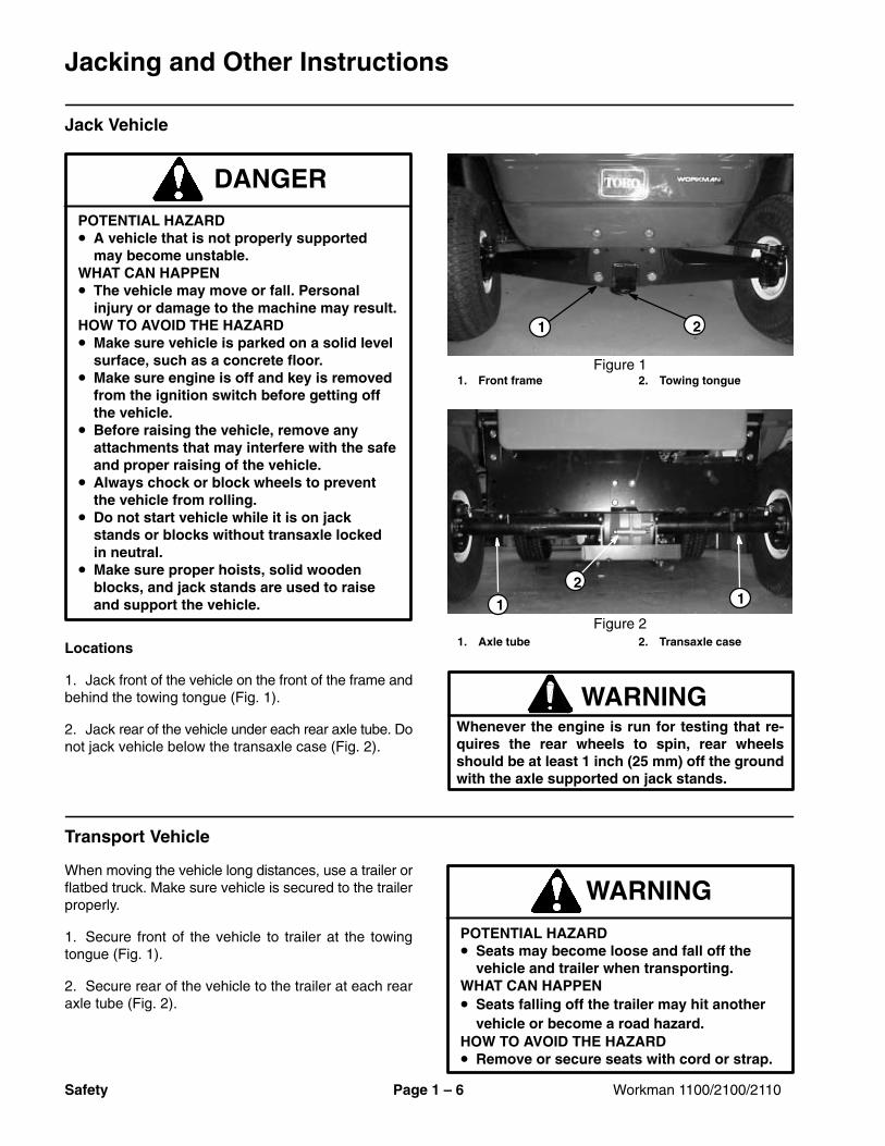
1. Jack front of the vehicle on the front of the frame andbehind the towing tongue (Fig. 1).
2. Jack rear of the vehicle under each rear axle tube. Donot jack vehicle below the transaxle case (Fig. 2).
1. Front frame 2. Towing tongueFigure 1
1 2
1. Axle tube 2. Transaxle caseFigure 2
2
1 1
WARNINGWhenever the engine is run for testing that re-quires the rear wheels to spin, rear wheelsshould be at least 1 inch (25 mm) off the groundwith the axle supported on jack stands.
Transport Vehicle
When moving the vehicle long distances, use a trailer orflatbed truck. Make sure vehicle is secured to the trailerproperly.
1. Secure front of the vehicle to trailer at the towingtongue (Fig. 1).
2. Secure rear of the vehicle to the trailer at each rearaxle tube (Fig. 2).
WARNINGPOTENTIAL HAZARD• Seats may become loose and fall off the
vehicle and trailer when transporting.WHAT CAN HAPPEN• Seats falling off the trailer may hit another
vehicle or become a road hazard.HOW TO AVOID THE HAZARD• Remove or secure seats with cord or strap.
Workman 1100/2100/2110 Page 1 – 7 Safety
Tow Vehicle
In case of emergency, the vehicle can be towed for ashort distance. However, Toro does not recommend thisas a standard procedure.
WARNING
POTENTIAL HAZARD• Towing at excessive speeds could cause
the vehicle to lose control.WHAT CAN HAPPEN• Loss of control could result in personnel
injury and/or damage to the vehicle.HOW TO AVOID THE HAZARD• Never tow vehicle more than 5 mph (8 KPH).
Towing the vehicle is a two person job. If the vehiclemust be moved a considerable distance, transport it ona truck or trailer (see Transport Vehicle).
1. Park machine on a level surface, stop engine, setparking brake, and remove key from the ignition switch.
2. Remove drive belt from drive and driven clutches(see Service Drive Belt).
3. Secure a chain or tow line to tongue on front framemember (Fig. 1).
4. Put vehicle in neutral (see Set Neutral Lock Assem-bly) and release parking brake.
Transaxle Neutral Position
When performing routine maintenance and/or enginetesting, the transaxle must be shifted into the neutralposition.
1. Park machine on a level surface, stop engine, setparking brake, and remove key from the ignition switch.
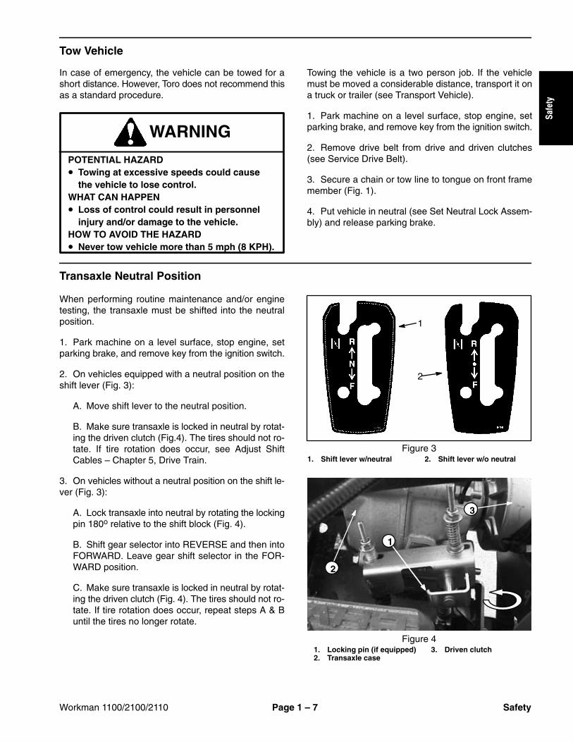
2. On vehicles equipped with a neutral position on theshift lever (Fig. 3):
A. Move shift lever to the neutral position.
B. Make sure transaxle is locked in neutral by rotat-ing the driven clutch (Fig.4). The tires should not ro-tate. If tire rotation does occur, see Adjust ShiftCables – Chapter 5, Drive Train.
3. On vehicles without a neutral position on the shift le-ver (Fig. 3):
A. Lock transaxle into neutral by rotating the lockingpin 180o relative to the shift block (Fig. 4).
B. Shift gear selector into REVERSE and then intoFORWARD. Leave gear shift selector in the FOR-WARD position.
C. Make sure transaxle is locked in neutral by rotat-ing the driven clutch (Fig. 4). The tires should not ro-tate. If tire rotation does occur, repeat steps A & Buntil the tires no longer rotate.
1. Shift lever w/neutral 2. Shift lever w/o neutralFigure 3
1
2
1. Locking pin (if equipped)2. Transaxle case
3. Driven clutchFigure 4
1
3
2
���
���
Workman 1100/2100/2110Page 1 – 8Safety
Safety and Instruction Decals
There are several safety and instruction decals attached to your Workman. If any decal becomes illegible or damaged,install a new decal. Part numbers are listed in the Parts Catalog. Order replacement decals from your Authorized ToroDistributor.
Rev. AWorkman 1100/2100/2110 Page 2 -- 1 Product Records and Maintenance
Insert Operator�s Manual and Parts Catalog for yourWorkman at the end of this chapter. Additionally, if anyoptional equipment or accessories have been installedto your machine, insert the Installation Instructions, Op-erator�s Manuals and Parts Catalogs for those optionsat the end of this chapter.
ProductRecords
andMaintenance
Workman 1100/2100/2110Page 2 – 2Product Records and Maintenance
Equivalents and Conversions
Workman 1100/2100/2110 Page 2 – 3 Product Records and Maintenance
Torque SpecificationsRecommended fastener torque values are listed in thefollowing tables. For critical applications, as determinedby Toro, either the recommended torque or a torque thatis unique to the application is clearly identified and spe-cified in this Service Manual.
These Torque Specifications for the installation andtightening of fasteners shall apply to all fasteners whichdo not have a specific requirement identified in this Ser-vice Manual. The following factors shall be consideredwhen applying torque: cleanliness of the fastener, useof a thread sealant (Loctite), degree of lubrication on thefastener, presence of a prevailing torque feature, hard-ness of the surface underneath the fastener’s head, orsimilar condition which affects the installation.
As noted in the following tables, torque values should bereduced by 25% for lubricated fasteners to achievethe similar stress as a dry fastener. Torque values mayalso have to be reduced when the fastener is threadedinto aluminum or brass. The specific torque valueshould be determined based on the aluminum or brassmaterial strength, fastener size, length of thread en-gagement, etc.
The standard method of verifying torque shall be per-formed by marking a line on the fastener (head or nut)and mating part, then back off fastener 1/4 of a turn.Measure the torque required to tighten the fastener untilthe lines match up.
Fastener Identification
Figure 1
Grade 1 Grade 5 Grade 8
Inch Series Bolts and Screws
Figure 2
Class 8.8 Class 10.9
Metric Bolts and Screws
��
�
�� �
��
��
��
���
���
���
��
Workman 1100/2100/2110Page 2 – 4Product Records and Maintenance
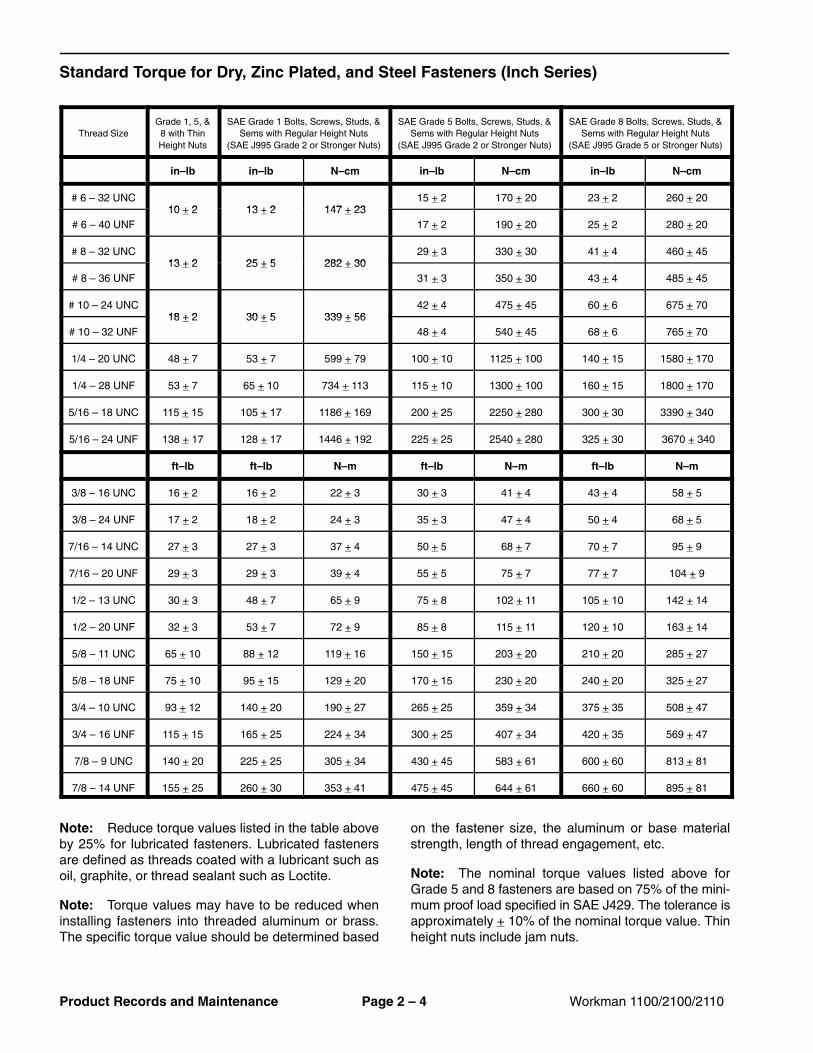
Standard Torque for Dry, Zinc Plated, and Steel Fasteners (Inch Series)
Note: Reduce torque values listed in the table aboveby 25% for lubricated fasteners. Lubricated fastenersare defined as threads coated with a lubricant such asoil, graphite, or thread sealant such as Loctite.
Note: Torque values may have to be reduced wheninstalling fasteners into threaded aluminum or brass.The specific torque value should be determined based
on the fastener size, the aluminum or base materialstrength, length of thread engagement, etc.
Note: The nominal torque values listed above forGrade 5 and 8 fasteners are based on 75% of the mini-mum proof load specified in SAE J429. The tolerance isapproximately + 10% of the nominal torque value. Thinheight nuts include jam nuts.
Workman 1100/2100/2110 Page 2 – 5 Product Records and Maintenance
Standard Torque for Dry, Zinc Plated, and Steel Fasteners (Metric Fasteners)
Thread SizeClass 8.8 Bolts, Screws, and Studs with
Regular Height NutsClass 10.9 Bolts, Screws, and Studs with
Note: Reduce torque values listed in the table aboveby 25% for lubricated fasteners. Lubricated fastenersare defined as threads coated with a lubricant such asoil, graphite, or thread sealant such as Loctite.
Note: Torque values may have to be reduced wheninstalling fasteners into threaded aluminum or brass.The specific torque value should be determined based
on the fastener size, the aluminum or base materialstrength, length of thread engagement, etc.
Note: The nominal torque values listed above arebased on 75% of the minimum proof load specified inSAE J1199. The tolerance is approximately + 10% of thenominal torque value.
��
�
�� �
��
��
��
���
���
���
��
Workman 1100/2100/2110Page 2 – 6Product Records and Maintenance
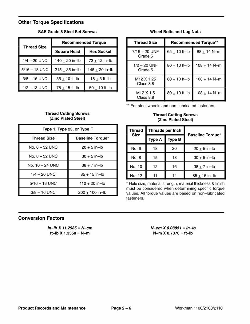
Other Torque Specifications
SAE Grade 8 Steel Set Screws
Thread SizeRecommended Torque
Thread SizeSquare Head Hex Socket
1/4 – 20 UNC 140 + 20 in–lb 73 + 12 in–lb
5/16 – 18 UNC 215 + 35 in–lb 145 + 20 in–lb
3/8 – 16 UNC 35 + 10 ft–lb 18 + 3 ft–lb
1/2 – 13 UNC 75 + 15 ft–lb 50 + 10 ft–lb
Thread Cutting Screws(Zinc Plated Steel)
Type 1, Type 23, or Type F
Thread Size Baseline Torque*
No. 6 – 32 UNC 20 + 5 in–lb
No. 8 – 32 UNC 30 + 5 in–lb
No. 10 – 24 UNC 38 + 7 in–lb
1/4 – 20 UNC 85 + 15 in–lb
5/16 – 18 UNC 110 + 20 in–lb
3/8 – 16 UNC 200 + 100 in–lb
Wheel Bolts and Lug Nuts
Thread Size Recommended Torque**
7/16 – 20 UNFGrade 5
65 + 10 ft–lb 88 + 14 N–m
1/2 – 20 UNFGrade 5
80 + 10 ft–lb 108 + 14 N–m
M12 X 1.25Class 8.8
80 + 10 ft–lb 108 + 14 N–m
M12 X 1.5Class 8.8
80 + 10 ft–lb 108 + 14 N–m
** For steel wheels and non–lubricated fasteners.
Thread Cutting Screws(Zinc Plated Steel)
ThreadSize
Threads per InchBaseline Torque*Size
Type A Type BBaseline Torque*
No. 6 18 20 20 + 5 in–lb
No. 8 15 18 30 + 5 in–lb
No. 10 12 16 38 + 7 in–lb
No. 12 11 14 85 + 15 in–lb
* Hole size, material strength, material thickness & finishmust be considered when determining specific torquevalues. All torque values are based on non–lubricatedfasteners.
Conversion Factors
in–lb X 11.2985 = N–cm N–cm X 0.08851 = in–lbft–lb X 1.3558 = N–m N–m X 0.7376 = ft–lb
Workman 1100/2100/2110 Page 2 – 7 Product Records and Maintenance
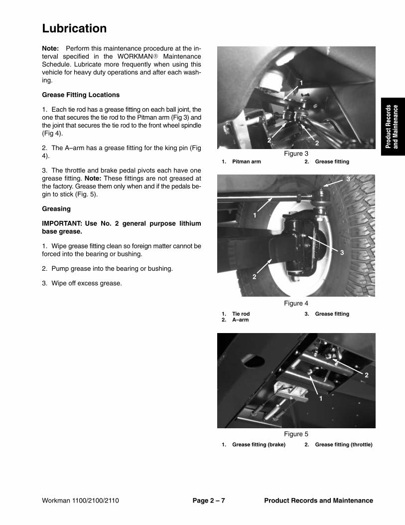
Lubrication
Note: Perform this maintenance procedure at the in-terval specified in the WORKMAN� MaintenanceSchedule. Lubricate more frequently when using thisvehicle for heavy duty operations and after each wash-ing.
Grease Fitting Locations
1. Each tie rod has a grease fitting on each ball joint, theone that secures the tie rod to the Pitman arm (Fig 3) andthe joint that secures the tie rod to the front wheel spindle(Fig 4).
2. The A–arm has a grease fitting for the king pin (Fig4).
3. The throttle and brake pedal pivots each have onegrease fitting. Note: These fittings are not greased atthe factory. Grease them only when and if the pedals be-gin to stick (Fig. 5).
Greasing
IMPORTANT: Use No. 2 general purpose lithiumbase grease.
1. Wipe grease fitting clean so foreign matter cannot beforced into the bearing or bushing.
Rev. A Workman 1100/2100/2110Page 2 -- 8Product Records and Maintenance
Drive Clutch Lubrication
Note: After every 400 hours of use, or yearly, cleaningand lubrication of the drive clutch is recommended.
1. Parkmachineona level surface, stopengine, and re-move key from the ignition switch.Raise and latch cargobed.
2. Remove the three (3) cap screws that secure thecover to the drive clutch (Fig. 6). Remove the cover fromthe clutch.
When using compressed air for cleaning theclutch, thedust in theclutchwill becomeairborneand could damage your eyes or you could inhaleit causing breathing difficulties.
Wear safety goggles andadustmaskor other eyeand respiratory protection when performing thisprocedure.
WARNING
3. Using compressed air, thoroughly clean the inside ofthe clutch cover and the clutch components.
4. Lubricate the clutch components as shown in Figure7 using Toro Dry Lubricant Spray (see Special Tools inChapter 5 -- Drive Train).
5. Install cover to clutch and secure with three (3) capscrews. Torque cap screws from 75 to 100 in--lb (8.5 to11.3 N--m).
1. Clutch cover 2. Cap screw
Figure 6
2
2
2
1
Figure 7
Maintenance
Maintenance procedures and recommended service in-tervals for your Workman are covered in the Operator�sManual. Refer to that publicationwhen performing regu-lar equipment maintenance.
This Chapter gives information about specifications,maintenance, troubleshooting, testing, and repair of theV�twin cylinder, gasoline engine used in the Workman2100 and 2110.
Most repairs and adjustments require tools which arecommonly available in many service shops. Specialtools are described in the Briggs & Stratton RepairManual for 4�Cycle, V�Twin Cylinder, OHV Head En-gines. The use of some specialized test equipment is ex-
plained. However, the cost of the test equipment and thespecialized nature of some repairs may dictate that thework be done at an engine repair facility.
Service and repair parts for Briggs & Stratton enginesare supplied through your local Briggs and Strattondealer or distributor. If no parts list is available, be sureto provide your distributor with the Toro model and serialnumber.
The Toro Company strongly recommends the use offresh, clean, UNLEADED regular grade gasoline in Torogasoline powered products. Unleaded gasoline burnscleaner, extends engine life, and promotes good startingby reducing the build-up of combustion chamber depos-its. Minimum Octane rating of 85.
IMPORTANT: Never use gasoline containing METH-ANOL, gasoline containing more than 10% ethanol,gasoline additives, or white gas. Damage could re-sult to the engine fuel system.
1. Park machine on a level surface, stop engine, en-gage parking brake, and remove key from the ignitionswitch.
2. Clean area around fuel tank cap.
3. Remove fuel tank cap.
4. Fill tank to about one inch below the top of tank, (bot-tom of filler neck). This space in the tank allows gasolineto expand. Do not overfill.
5. Install fuel tank cap securely. Wipe up any fuel thatmay have spilled.
Figure 11. Fuel tank cap 2. Fuel gauge
1
2
DANGER
POTENTIAL HAZARD• Gasoline is extremely flammable and highly
explosive under certain conditions.
WHAT CAN HAPPEN• A fire or explosion from gasoline can burn
you, others, and cause property damage.
HOW TO AVOID THE HAZARD• Use a funnel and fill the fuel tank outdoors,
in an open area, when the engine is cold.Wipe up any gasoline that spills.
• Do not fill the fuel tank completely full. Addgasoline to the fuel tank until the level is nohigher than 1 inch (25 mm) below thebottom of the filler neck. This empty spacein the tank allows gasoline to expand.
• Never smoke when handling gasoline, andstay away from an open flame or wheregasoline fumes may be ignited by a spark.
• Store gasoline in an approved containerand keep it out of the reach of children.Never buy more than a 30-day supply ofgasoline.
• Always place gasoline containers on theground away from your vehicle beforefilling.
• Do not fill gasoline containers inside avehicle or on a truck or trailer bed becauseinterior carpets or plastic truck bed linersmay insulate the container and slow theloss of any static charge.
• When practical, remove gas�poweredequipment from the truck or trailer andrefuel the equipment with its wheels on theground.
• If this is not possible, then refuel suchequipment on a truck or trailer from aportable container, rather than from agasoline dispenser nozzle.
• If a gasoline dispenser nozzle must beused, keep the nozzle in contact with therim of the fuel tank or container opening atall times until fueling is complete.
The engine is shipped with oil in the crankcase; howev-er, level of oil must be checked before and after the en-gine is first started.
1. Park machine on a level surface, stop engine, en-gage parking brake, and remove key from the ignitionswitch.
2. Remove dipstick and wipe it with a clean rag. Insertdipstick into tube and make sure it is seated fully. Re-move dipstick and check level of oil.
3. If oil level is low, remove filler cap from valve cover.Pour oil with proper type and viscosity into the openinguntil the oil level is up to the �FULL� mark on the dipstick.Add oil slowly, and check the level often during this pro-cess. Do not overfill.
Note: Perform this maintenance procedure at the in-terval specified in the Operator�s Manual or Chapter 2� Product Records and Maintenance.
1. Park machine on a level surface, stop engine, en-gage parking brake, and remove key from the ignitionswitch.
2. Loosen starter generator pivot bolt.
3. While pressing the belt at mid�span between the pul-leys with 10 lb (44.5 N) of force, adjust jam nut on thestarter rod until the belt flexes 1/4 inch (6 mm).
4. Tighten starter generator pivot bolt.Figure 4
1. Generator pivot bolt2. Jam nut
3. Starter rod4. Torque arm
1
2
10 lbs.1/4�3
4
Adjust Throttle Cable
Note: Workman 2100 and 2110 machines with SerialNumbers above 240000000 are equipped with an en-gine governor rather than a transaxle governor. Refer tothe Briggs & Stratton Repair Manual at the end of thischapter for governor information on these machines.
Releasing the accelerator pedal should allow the throttlecable to close the carburetor throttle control lever so thatthe lever touches the adjustment screw. The adjustmentscrew keeps the throttle valve inside the carburetoropen slightly to prevent the valve from binding.
1. Park machine on a level surface, stop engine, en-gage parking brake, and remove key from the ignitionswitch.
2. Lift cargo bed and prop with rod to gain access to theengine.
3. Rotate governor arm on transaxle fully clockwise(Fig. 5).
4. Make sure of the following:
A. The engine throttle control lever should be to thefully open position (Fig. 6).
B. Adjust throttle cable at the cable bracket as nec-essary, so there is no compression of the throttlecable (Fig. 5). This will allow the throttle control leverto fully close when the accelerator pedal is released.
Note: Perform this maintenance procedure at the in-terval specified in the Operator�s Manual or Chapter 2� Product Records and Maintenance.
1. Start vehicle and let it run for a few minutes to warmthe oil.
2. Park machine on a level surface, stop engine, en-gage parking brake, and remove key from the ignitionswitch.
3. Raise bed and support with prop rod (see Operator�sManual).
4. Disconnect spark plug wires.
5. Remove drain plug and let the oil flow into a drainpan. When the oil stops, reinstall the drain plug (Fig.7).
Note: Dispose of the used oil at a certified recyclingcenter.
Note: See Check Engine Oil for the proper type andviscosity of oil to add to the engine.
6. Pour oil into fill opening until the oil level is up to the�FULL� mark on the dipstick. Add oil slowly and checklevel often during this process. Do not overfill (Fig. 8).
7. Install filler cap and dipstick firmly in place (Fig. 8).
8. Connect spark plug wires.
Figure 71. Drain plug 2. Oil filter
1
2
Figure 81. Dipstick 2. Filler cap
1
2
Change Engine Oil Filter
Note: Perform this maintenance procedure at the in-terval specified in the Operator�s Manual or Chapter 2� Product Records and Maintenance.
1. Drain oil from the engine (see Change Engine Oil).
2. Remove existing oil filter (Fig.7). Apply light coat ofclean oil to the new filter gasket.
3. Screw filter on until gasket contacts mounting plate,then tighten filter an additional 1/2 to 3/4 turn further. Donot overtighten.
Note: See Check Engine Oil for the proper type andviscosity of oil to add to the engine.
4. Pour oil into fill opening until the oil level is up to the�FULL� mark on the dipstick. Add oil slowly and checklevel often during this process. Do not overfill (Fig. 8).
5. Start and run engine to check for leaks.
6. Stop engine and recheck the oil level. Add oil if nec-essary.
Note: Perform this maintenance procedure at the in-terval specified in the Operator�s Manual or Chapter 2� Product Records and Maintenance.
1. Park machine on a level surface, stop engine, en-gage parking brake, and remove key from the ignitionswitch.
2. Raise bed and support with prop rod (see Operator�sManual).
3. Check air cleaner body and hoses for damage whichcould possibly cause an air leak. Replace air cleanerbody if damaged.
4. Release latches securing the air cleaner cover to theair cleaner body. Separate cover from the body. Cleaninside of air cleaner cover.
5. Gently slide filter out of the air cleaner body to reducethe amount of dust dislodged. Avoid knocking filteragainst the air cleaner body.
IMPORTANT: Do not wash or reuse a damaged filter.
6. Inspect filter. Discard filter if damaged.
7. Clean filter element using either the washing methodor compressed air method:
Washing Method
A. Prepare a solution of filter cleaner and water.Soak filter element for about 15 minutes. Refer todirections on the filter cleaner carton for complete in-formation.
IMPORTANT: Maximum water pressure must notexceed 40 psi to prevent damage to the filter ele-ment.
B. After soaking the filter for 15 minutes, rinse it withclear water. Rinse filter from the clean side to the dirtyside.
IMPORTANT: Do not use a light bulb to dry the filterelement because damage could result.
C. Dry filter element using warm, flowing air thatdoes not to exceed 160oF (71oC), or allow element toair�dry.
Compressed Air Method
CAUTION
Use eye protection such as goggles when usingcompressed air.
IMPORTANT: Maximum air pressure must not ex-ceed 100 psi to prevent damage to the element.
A. Blow compressed air from the inside to the out-side of the dry filter element.
B. Keep air hose nozzle at least 2 inches (5 cm) fromthe filter. Move nozzle up and down while rotating thefilter element. Inspect for holes and tears by lookingthrough the filter toward a bright light.
8. If filter element is being replaced, inspect new filterfor shipping damage. Check sealing end of the filter. Donot install a damaged filter.
9. Insert new (or cleaned) filter correctly into the aircleaner body. Make sure filter is sealed properly by ap-plying pressure to the outer rim of the filter when instal-ling. Do not press on the flexible center of the filter.
Note: Perform this maintenance procedure at the in-terval specified in the Operator�s Manual or Chapter 2� Product Records and Maintenance.
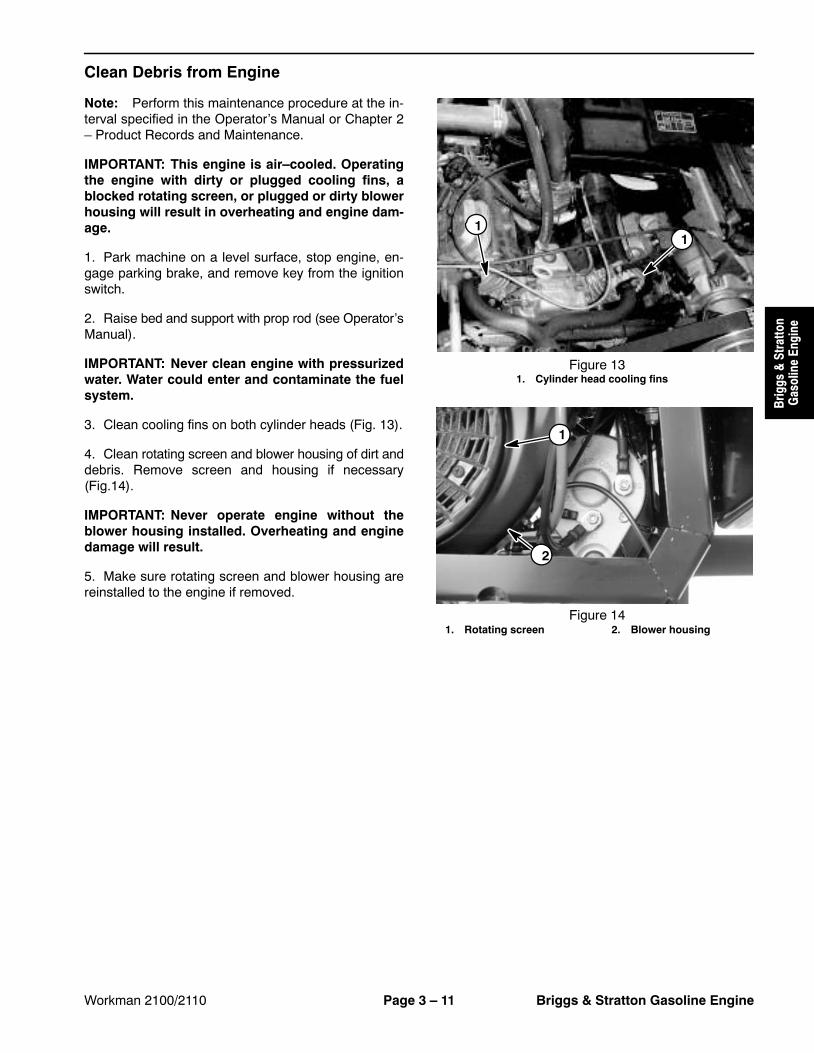
IMPORTANT: This engine is air�cooled. Operatingthe engine with dirty or plugged cooling fins, ablocked rotating screen, or plugged or dirty blowerhousing will result in overheating and engine dam-age.
1. Park machine on a level surface, stop engine, en-gage parking brake, and remove key from the ignitionswitch.
2. Raise bed and support with prop rod (see Operator�sManual).
IMPORTANT: Never clean engine with pressurizedwater. Water could enter and contaminate the fuelsystem.
3. Clean cooling fins on both cylinder heads (Fig. 13).
4. Clean rotating screen and blower housing of dirt anddebris. Remove screen and housing if necessary(Fig.14).
IMPORTANT: Never operate engine without theblower housing installed. Overheating and enginedamage will result.
5. Make sure rotating screen and blower housing arereinstalled to the engine if removed.
1. Park machine on a level surface, stop the engine, en-gage parking brake, and remove the key from the igni-tion switch.
2. Raise bed and support with prop rod.
CAUTION
The muffler and exhaust pipe may be hot. Toavoid possible burns, allow engine and exhaustsystem to cool before working on the muffler.
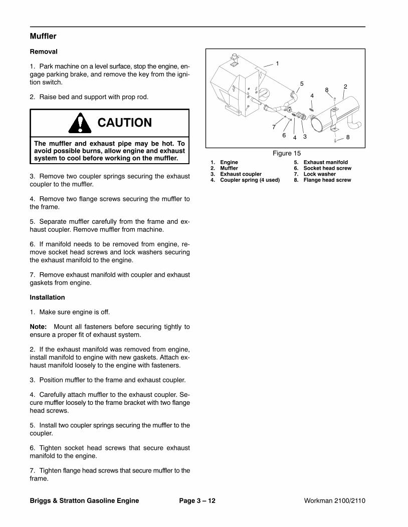
3. Remove two coupler springs securing the exhaustcoupler to the muffler.
4. Remove two flange screws securing the muffler tothe frame.
5. Separate muffler carefully from the frame and ex-haust coupler. Remove muffler from machine.
6. If manifold needs to be removed from engine, re-move socket head screws and lock washers securingthe exhaust manifold to the engine.
7. Remove exhaust manifold with coupler and exhaustgaskets from engine.
Installation
1. Make sure engine is off.
Note: Mount all fasteners before securing tightly toensure a proper fit of exhaust system.
2. If the exhaust manifold was removed from engine,install manifold to engine with new gaskets. Attach ex-haust manifold loosely to the engine with fasteners.
3. Position muffler to the frame and exhaust coupler.
4. Carefully attach muffler to the exhaust coupler. Se-cure muffler loosely to the frame bracket with two flangehead screws.
5. Install two coupler springs securing the muffler to thecoupler.
6. Tighten socket head screws that secure exhaustmanifold to the engine.
7. Tighten flange head screws that secure muffler to theframe.
Figure 151. Engine2. Muffler3. Exhaust coupler4. Coupler spring (4 used)
5. Exhaust manifold6. Socket head screw7. Lock washer8. Flange head screw
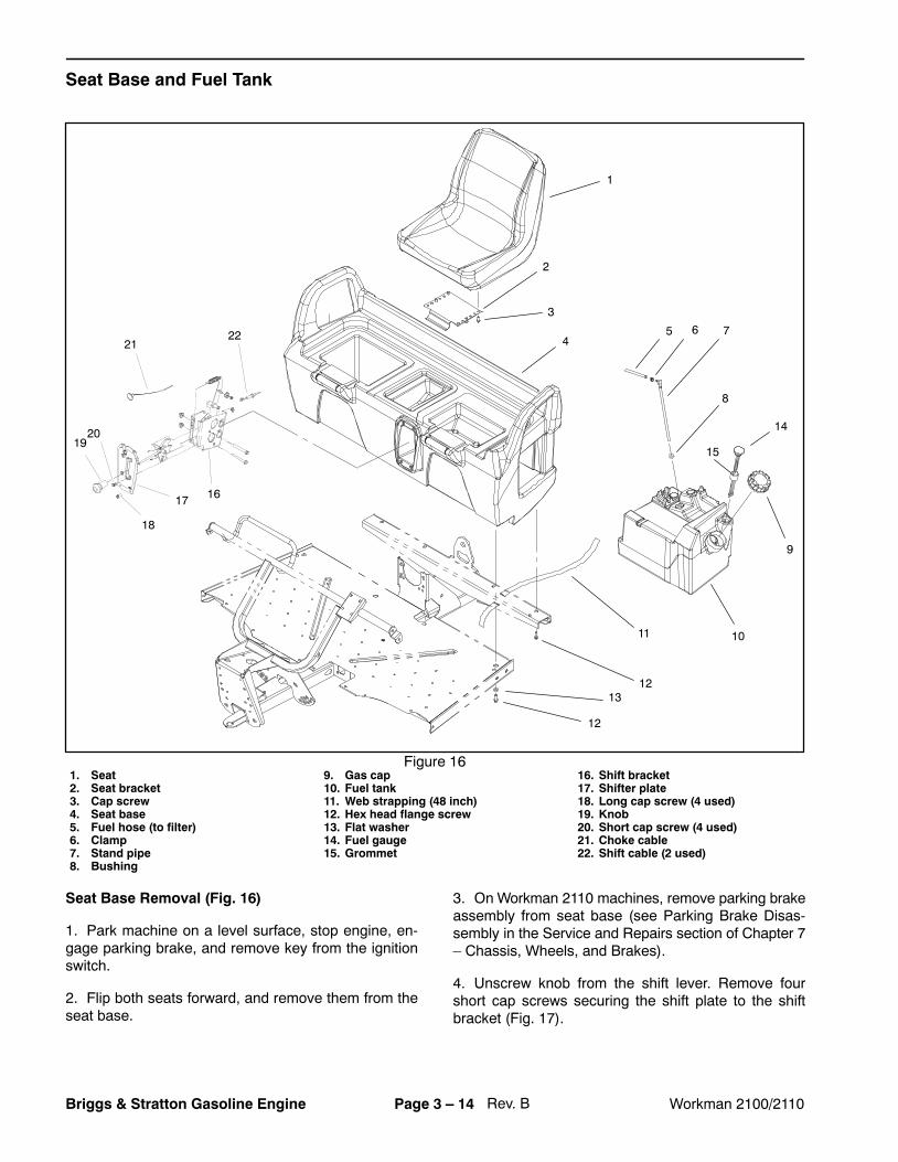
1. Seat2. Seat bracket3. Cap screw4. Seat base5. Fuel hose (to filter)6. Clamp7. Stand pipe8. Bushing
9. Gas cap10. Fuel tank11. Web strapping (48 inch)12. Hex head flange screw13. Flat washer14. Fuel gauge15. Grommet
16. Shift bracket17. Shifter plate18. Long cap screw (4 used)19. Knob20. Short cap screw (4 used)21. Choke cable22. Shift cable (2 used)
Figure 16
1
2
3
47
8
9
1011
12
5 6
12
13
14
15
16
2221
17
18
2019
Seat Base Removal (Fig. 16)
1. Park machine on a level surface, stop engine, en-gage parking brake, and remove key from the ignitionswitch.
2. Flip both seats forward, and remove them from theseat base.
3. On Workman 2110 machines, remove parking brakeassembly from seat base (see Parking Brake Disas-sembly in the Service and Repairs section of Chapter 7� Chassis, Wheels, and Brakes).
4. Unscrew knob from the shift lever. Remove fourshort cap screws securing the shift plate to the shiftbracket (Fig. 17).
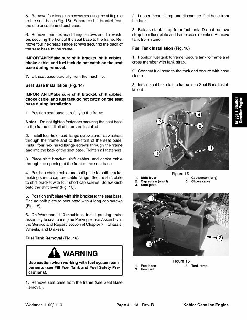
5. Remove four long cap screws securing the shift plateto the seat base (Fig. 17). Separate shift bracket fromthe choke cable and seat base.
6. Remove four hex head flange screws and flat wash-ers securing the front of the seat base to the frame. Re-move four hex head flange screws securing the back ofthe seat base to the frame.
IMPORTANT:Make sure shift bracket, shift cables,choke cable, and fuel tank do not catch on the seatbase during removal.
7. Lift seat base carefully from the machine.
Seat Base Installation
IMPORTANT:Make sure shift bracket, shift cables,choke cable, and fuel tank do not catch on the seatbase during installation.
1. Position seat base carefully to the frame.
Note: Do not tighten fasteners securing the seat baseto the frame until all of them are installed.
2. Install four hex head flange screws and flat washersthrough the frame and to the front of the seat base.Install four hex head flange screws through the frameand into the back of the seat base. Tighten all fasteners.
3. Place shift bracket, shift cables, and choke cablethrough the opening at the front of the seat base.
4. Position choke cable and shift plate to shift bracketmaking sure to capture cable flange. Secure shift plateto shift bracket with four short cap screws. Screw knobonto the shift lever (Fig. 17).
5. Position shift plate with shift bracket to the seat base.Secure shift plate to seat base with 4 long cap screws(Fig. 17).
6. On Workman 2110 machines, install parking brakeassembly to seat base (see Parking Brake Assembly inthe Service and Repairs section of Chapter 7 � Chassis,Wheels, and Brakes).
Fuel Tank Removal (Fig. 18)
WARNINGUse caution when working with fuel system com-ponents (see Fill Fuel Tank and Fuel Safety Pre-cautions).
1. Remove seat base from the frame (see Seat BaseRemoval).
2. Loosen hose clamp and disconnect fuel hose fromthe tank.
3. Release tank strap from fuel tank. Do not removestrap from floor plate and frame cross member. Removetank from frame.
Fuel Tank Installation (Fig. 18)
1. Position fuel tank to frame. Secure tank to frame andcross member with tank strap.
2. Connect fuel hose to the tank and secure with hoseclamp.
3. Install seat base to the frame (see Seat Base Instal-lation).
1. Park machine on a level surface, stop engine, en-gage parking brake, and remove key from the ignitionswitch.
2. Remove cargo bed to gain access to the engine.
3. Disconnect negative (black) cable from the battery.Then, disconnect positive (red) cable from the battery.
IMPORTANT: Make sure all hoses and engine open-ings are plugged after disconnecting. Prevent con-taminants from entering the engine and fuel systemand damaging the engine.
4. Disconnect the following components:
A. Choke and throttle cables from the carburetorand cable bracket (Fig. 20).
B. Air intake hose from the carburetor (Fig. 21).
C. Breather hose from the crankcase (Fig. 21).
CAUTIONRead safety precautions for handling gasolinebefore working on the fuel system (see Fill FuelTank and Fuel Safety Precautions).
5. Disconnect fuel hose from the fuel pump. Removecable tie securing the choke, throttle, and shift cables tothe bracket on the front cylinder head (Fig. 21).
6. Remove muffler and exhaust pipe from the cylinderheads (see Muffler Removal).
7. Remove drive belt (see Service Drive Belt).
8. Remove V�belt from the engine and starter/genera-tor by loosening the tension on the belt. Disconnectstarter rod from the torque arm (see Adjust Starter/Gen-erator Belt).
9. Remove torque arm from the engine and transaxle.
10.Disconnect electrical connections from the followingengine components:
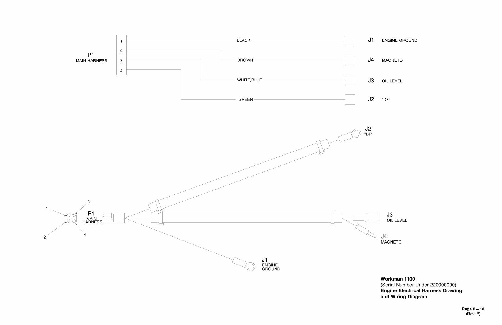
A. Disconnect ground cable to engine at starter/generator terminal A1 (Fig. 22).
B. Disconnect engine harness connector from themain harness.
11.Remove four flange lock nuts and cap screws secur-ing the engine to the engine mount.
CAUTIONOne person should operate the chain fall or hoistwhile the other person guides the engine out ofthe frame.
12.Remove engine from the engine mount.
A. Attach a short section of chain between both en-gine lift tabs.
B. Connect hoist or chain fall to center of chain.
IMPORTANT: Make sure not to damage the engine,fuel hoses, electrical harness, or other parts whileremoving the engine.
C. Slowly remove engine and mounts from the ma-chine.
13.Remove engine parts and attachments as neces-sary to repair the engine.
Engine Installation (Fig. 19)
1. If removed, install engine parts and attachments tothe engine.
CAUTIONOne person should operate the chain fall or hoistwhile the other person guides the engine into theframe.
2. Install engine to the frame.
A. Attach a short section of chain between both en-gine lift tabs.
B. Connect a hoist or chain fall at the center of theshort section of chain.
IMPORTANT: Make sure not to damage engine, fuellines, electrical harness, or other parts while instal-ling the engine.
C. Carefully lower engine onto the engine mount.
3. Secure engine to the engine mount with flange locknuts and cap screws.
4. Connect the following electrical components:
A. Connect ground cable from the engine at starter/generator terminal A1 (Fig. 22).
B. Connect engine harness connector to the mainharness connector.
5. Install torque arm to the engine and transaxle.
6. Secure starter rod to the torque arm. Install V�belt tothe engine and starter/generator. Tension and adjust theV�belt (see Adjust Starter/Generator Belt).
7. Install drive belt (see Service Drive Belt).
8. Install muffler and exhaust pipe to the cylinder heads(see Muffler Removal).
9. Connect fuel hose to the fuel pump (Fig. 21).
10.Connect the following components:
IMPORTANT: Make sure all hoses and engine open-ing plugs are removed.
A. Choke and throttle cables to the carburetor andcable bracket (Fig. 20).
B. Air intake hose to the carburetor (Fig. 21).
C. Breather hose to the crankcase (Fig. 21).
11.Secure choke, throttle, and shift cables to the brack-et on the front cylinder head with cable tie (Fig. 21).
12.Connect positive (red) cable to the battery. Then,connect negative (black) cable to the battery.
13.Install cargo bed to the frame.
14.Make sure engine oil level is correct (see Check En-gine Oil).
15.When starting a new or repaired engine, observe thefollowing:
A. After starting a cold engine, let it warm up forabout 15 seconds before applying any load to it.
B. Check engine oil level regularly. Be alert for con-ditions of overheating.
KOHLER SERVICE MANUAL FOR COMMAND PROCS SERIES ENGINES
��
���
���
�
����
�
���
�
Rev. B Workman 1100/1110Page 4 � 2Kohler Gasoline Engine
Introduction
This Chapter gives information about specifications,maintenance, troubleshooting, testing, and repair of theKohler gasoline engine used in the Workman 1100 and1110.
Most repairs and adjustments require tools which arecommonly available in many service shops. Specialtools are described in the Kohler Service Manual forCOMMAND PRO CS Series Engines. The use of some
specialized test equipment is explained. However, thecost of the test equipment and the specialized nature ofsome repairs may dictate that the work be done at an en-gine repair facility.
Service and repair parts for Kohler engines are suppliedthrough your local Kohler dealer or distributor. If no partslist is available, be sure to provide your distributor withthe Toro model and serial number.
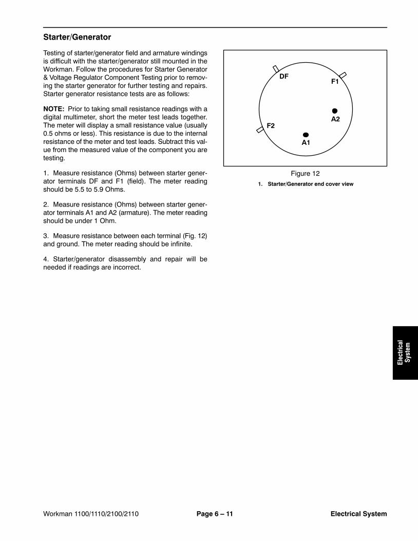
Starter/Generator 10.5 VDC 100 Amps/14 VDC and 23 Amps
��
���
���
�
����
�
���
�
Workman 1100/1110Page 4 � 4Kohler Gasoline Engine
General Information
Fill Fuel Tank and Fuel Safety Precautions
The Toro Company strongly recommends the use offresh, clean, UNLEADED regular grade gasoline in Torogasoline powered products. Unleaded gasoline burnscleaner, extends engine life, and promotes good startingby reducing the build-up of combustion chamber depos-its. Minimum Octane rating of 87.
IMPORTANT: Never use gasoline containing METH-ANOL, gasoline containing more than 10% ethanol,gasoline additives, or white gas. Damage could re-sult to the engine fuel system.
1. Park machine on a level surface, stop engine, en-gage parking brake, and remove key from the ignitionswitch.
2. Clean area around fuel tank cap.
3. Remove fuel tank cap.
4. Fill tank to about one inch below the top of tank, (bot-tom of filler neck). This space in the tank allows gasolineto expand. Do not overfill.
5. Install fuel tank cap securely. Wipe up any fuel thatmay have spilled.
Figure 11. Fuel tank cap 2. Fuel gauge
1
2
DANGERPOTENTIAL HAZARD• Gasoline is extremely flammable and highly
explosive under certain conditions.
WHAT CAN HAPPEN• A fire or explosion from gasoline can burn
you, others, and cause property damage.
HOW TO AVOID THE HAZARD• Use a funnel and fill the fuel tank outdoors,
in an open area, when the engine is cold.Wipe up any gasoline that spills.
• Do not fill the fuel tank completely full. Addgasoline to the fuel tank until the level is nohigher than 1 inch (25 mm) below thebottom of the filler neck. This empty spacein the tank allows gasoline to expand.
• Never smoke when handling gasoline, andstay away from an open flame or wheregasoline fumes may be ignited by a spark.
• Store gasoline in an approved containerand keep it out of the reach of children.Never buy more than a 30-day supply ofgasoline.
• Always place gasoline containers on theground away from your vehicle beforefilling.
• Do not fill gasoline containers inside avehicle or on a truck or trailer bed becauseinterior carpets or plastic truck bed linersmay insulate the container and slow theloss of any static charge.
• When practical, remove gas�poweredequipment from the truck or trailer andrefuel the equipment with its wheels on theground.
• If this is not possible, then refuel suchequipment on a truck or trailer from aportable container, rather than from agasoline dispenser nozzle.
• If a gasoline dispenser nozzle must beused, keep the nozzle in contact with therim of the fuel tank or container opening atall times until fueling is complete.
The engine is shipped with oil in the crankcase; howev-er, level of oil must be checked before and after the en-gine is first started.
1. Park machine on a level surface, stop engine, en-gage parking brake, and remove key from the ignitionswitch.
2. Remove dipstick and wipe it with a clean rag. Insertdipstick into tube and make sure it is seated fully. Re-move dipstick and check level of oil.
3. If oil level is low, pour oil with proper type and viscos-ity into the filler tube until the oil level is up to the �FULL�mark on the dipstick. Add oil slowly, and check the leveloften during this process. Do not overfill.
4. Install dipstick firmly in place.
Oil Type and Viscosity (Fig. 3)
Oil Type: Detergent oil (API service SG, SH, SJ, or high-er).
Figure 21. Dipstick 2. Filler tube
1
2
Figure 3
o�20 0 20 40 60 80 100
C�30 �20 �10 0 10 20 30 40
10W-30
5W-20, 5W-30
10W 20W 30W
USE THESE SAE VISCOSITY OILS
o
F
��
���
���
�
����
�
���
�
Workman 1100/1110Page 4 � 6Kohler Gasoline Engine
Adjustments
Adjust Starter/Generator Belt
Note: Perform this maintenance procedure at the in-terval specified in the Operator�s Manual or Chapter 2� Product Records and Maintenance.
1. Park machine on a level surface, stop engine, en-gage parking brake, and remove key from the ignitionswitch.
2. Lift cargo bed and prop with rod to gain access to theengine.
3. Loosen starter/generator pivot bolt.
4. Wedge a pry bar between the engine mount andstarter. Loosen the nut on the adjusting carriage bolt.
5. Pivot the starter in the slot until the belt flexes 1/4 inch(6 mm), with 10 lb (4.5 Kg) of force.
Releasing the accelerator pedal should allow the throttlecable to close the carburetor throttle control lever so thatthe lever touches the adjustment screw. The adjustmentscrew keeps the throttle valve inside the carburetoropen slightly to prevent the valve from binding.
1. Park machine on a level surface, stop engine, en-gage parking brake, and remove key from the ignitionswitch.
2. Lift cargo bed and prop with rod to gain access to theengine.
3. Rotate governor arm fully clockwise (Fig. 5).
4. Make sure of the following:
A. The throttle control lever should be to the fullyopen position.
B. Adjust throttle cable at the cable bracket as nec-essary, so there is no compression of the throttlecable (Fig. 5). This will allow the throttle control leverto fully close when the accelerator pedal is released.
Note: Perform this maintenance procedure at the in-terval specified in the Operator�s Manual or Chapter 2� Product Records and Maintenance.
1. Start vehicle and let it run for a few minutes to warmthe oil.
2. Park machine on a level surface, stop engine, en-gage parking brake, and remove key from the ignitionswitch.
3. Raise bed and secure it with the prop rod.
4. Disconnect spark plug wire.
5. Remove drain plug and let the oil flow into a drainpan. When the oil stops, reinstall the drain plug (Fig. 6)and torque it to 13 ft�lb (17.6 N�m).
Note: Dispose of the used oil at a certified recyclingcenter.
Note: See Check Engine Oil for the proper type andviscosity of oil to add to the engine.
6. Pour oil into filler tube until the oil level is up to the�FULL� mark on the dipstick. Add oil slowly and checklevel often during this process. Do not overfill (Fig. 7).
7. Install dipstick firmly in place (Fig. 7).
8. Connect spark plug wire.
Figure 61. Drain plug
1
Figure 71. Dipstick 2. Filler tube
1
2 ��
���
���
�
����
�
���
�
Workman 1100/1110Page 4 � 8Kohler Gasoline Engine
Service Air Cleaner
Note: Perform this maintenance procedure at the in-terval specified in the Operator�s Manual or Chapter 2� Product Records and Maintenance.
1. Park machine on a level surface, stop engine, en-gage parking brake, and remove key from the ignitionswitch.
2. Raise bed and secure with prop.
3. Check air cleaner body and hoses for damage whichcould possibly cause an air leak. Replace air cleanerbody if damaged.
4. Release latches securing the air cleaner cover to theair cleaner body. Separate cover from the body. Cleaninside of air cleaner cover.
5. Gently slide filter out of the air cleaner body to reducethe amount of dust dislodged. Avoid knocking filteragainst the air cleaner body.
IMPORTANT: Do not wash or reuse a damaged filter.
6. Inspect filter. Discard filter if damaged.
7. Clean filter element using either of the following twomethods:
Washing Method
A. Prepare a solution of filter cleaner and water.Soak filter element for about 15 minutes. Refer todirections on the filter cleaner carton for complete in-formation.
IMPORTANT: Maximum water pressure must notexceed 40 psi to prevent damage to the filter ele-ment.
B. After soaking the filter for 15 minutes, rinse it withclear water. Rinse filter from the clean side to the dirtyside.
IMPORTANT: Do not use a light bulb to dry the filterelement because damage could result.
C. Dry filter element using warm, flowing air thatdoes not to exceed 160oF (71oC), or allow element toair�dry.
Compressed Air Method
CAUTION
Use eye protection such as goggles when usingcompressed air.
IMPORTANT: Maximum air pressure must not ex-ceed 100 psi to prevent damage to the element.
A. Blow compressed air from the inside to the out-side of the dry filter element.
B. Keep air hose nozzle at least 2 inches (5 cm) fromthe filter. Move nozzle up and down while rotating thefilter element. Inspect for holes and tears by lookingthrough the filter toward a bright light.
8. If filter element is being replaced, inspect new filterfor shipping damage. Check sealing end of the filter. Donot install a damaged filter.
9. Insert new (or cleaned) filter correctly into the aircleaner body. Make sure filter is sealed properly by ap-plying pressure to the outer rim of the filter when instal-ling. Do not press on the flexible center of the filter.
Note: A spark plug usually lasts a long time; however,the plug should be removed and checked whenever theengine malfunctions.
1. Park machine on a level surface, stop engine, en-gage parking brake, and remove key from the ignitionswitch.
2. Raise bed and support with prop rod.
3. Clean area around spark plug so foreign matter can-not fall into cylinder when spark plug is removed.
4. Pull spark plug wire off spark plug and remove plugfrom cylinder head.
IMPORTANT: Replace cracked, fouled, dirty, or mal-functioning spark plug. Do not clean plug. Grit fromthe plug may damage the engine.
5. Check condition of side electrode, center electrode,and center electrode insulator for damage.
6. Set air gap between center and side electrodes at0.030� (0.76 mm). Install correctly gapped spark plugand tighten plug to 14 ft-lb (20 N�m).
7. Install spark plug wire.
Figure 11
.030�(.76 mm)
Clean Debris from Engine
Note: Perform this maintenance procedure at the in-terval specified in the Operator�s Manual or Chapter 2� Product Records and Maintenance.
IMPORTANT: This engine is air�cooled. Operatingthe engine with dirty or plugged cooling fins, ablocked debris screen, or a plugged or dirty blowerhousing will result in overheating and engine dam-age.
1. Park machine on a level surface, stop engine, en-gage parking brake, and remove key from the ignitionswitch.
2. Raise bed and support with prop rod.
IMPORTANT: Never clean engine with pressurizedwater. Water could enter and contaminate the fuelsystem.
3. Clean cooling fins on cylinder head.
4. Clean static debris screen and blower housing of dirtand debris. Remove screen and housing if necessary(Fig. 12).
IMPORTANT: Never operate engine without theblower housing installed. Overheating and enginedamage will result.
5. Make sure static screen and blower housing are rein-stalled to the engine if removed.
1. Park machine on a level surface, stop the engine, en-gage parking brake, and remove the key from the igni-tion switch.
2. Raise bed and support with prop rod.
CAUTION
The muffler and exhaust pipe may be hot. Toavoid possible burns, allow engine and exhaustsystem to cool before working on the muffler.
3. Remove springs securing the exhaust coupler to themuffler and exhaust manifold (Fig. 13).
4. Remove four screws securing the muffler to theframe.
5. Remove exhaust coupler and muffler.
6. If needed, remove exhaust manifold from engine byremoving two exhaust nuts. Replace gasket if neces-sary.
Installation
1. Make sure engine is off.
Note: Mount all exhaust fasteners before tightening toensure a proper fit.
2. If the exhaust manifold was removed, install man-ifold to engine with new gasket. Position manifold loose-ly to the engine with exhaust nuts.
3. Install muffler to the frame with four screws.
4. Insert coupler between muffler and manifold. Installsprings to attach coupler to the exhaust manifold andmuffler.
5. Tighten all fasteners.
Figure 131. Exhaust manifold2. Exhaust coupler
3. Spring
3
1
2
33
��
���
���
�
����
�
���
�
Rev. B Workman 1100/1110Page 4 � 12Kohler Gasoline Engine
Seat Base and Fuel Tank
1. Seat2. Seat bracket3. Cap screw4. Seat base5. Fuel hose (to filter)6. Clamp7. Stand pipe8. Bushing
9. Gas cap10. Fuel tank11. Web strapping (48 inch)12. Hex head flange screw13. Flat washer14. Fuel gauge15. Grommet
16. Shift bracket17. Shifter plate18. Long cap screw (4 used)19. Knob20. Short cap screw (4 used)21. Choke cable22. Shift cable (2 used)
Figure 14
1
2
3
47
8
9
1011
12
5 6
12
13
14
15
16
2221
17
18
2019
Seat Base Removal (Fig. 14)
1. Park machine on a level surface, stop engine, en-gage parking brake, and remove key from the ignitionswitch.
2. Flip both seats forward, and remove them from theseat base.
3. On Workman 1110 machines, remove parking brakeassembly from seat base (see Parking Brake Disas-sembly in the Service and Repairs section of Chapter 7� Chassis, Wheels, and Brakes).
4. Unscrew knob from the shift lever. Remove fourshort cap screws securing the shift plate to the shiftbracket (Fig. 15).
5. Remove four long cap screws securing the shift plateto the seat base (Fig. 15). Separate shift bracket fromthe choke cable and seat base.
6. Remove four hex head flange screws and flat wash-ers securing the front of the seat base to the frame. Re-move four hex head flange screws securing the back ofthe seat base to the frame.
IMPORTANT:Make sure shift bracket, shift cables,choke cable, and fuel tank do not catch on the seatbase during removal.
7. Lift seat base carefully from the machine.
Seat Base Installation (Fig. 14)
IMPORTANT:Make sure shift bracket, shift cables,choke cable, and fuel tank do not catch on the seatbase during installation.
1. Position seat base carefully to the frame.
Note: Do not tighten fasteners securing the seat baseto the frame until all of them are installed.
2. Install four hex head flange screws and flat washersthrough the frame and to the front of the seat base.Install four hex head flange screws through the frameand into the back of the seat base. Tighten all fasteners.
3. Place shift bracket, shift cables, and choke cablethrough the opening at the front of the seat base.
4. Position choke cable and shift plate to shift bracketmaking sure to capture cable flange. Secure shift plateto shift bracket with four short cap screws. Screw knobonto the shift lever (Fig. 15).
5. Position shift plate with shift bracket to the seat base.Secure shift plate to seat base with 4 long cap screws(Fig. 15).
6. On Workman 1110 machines, install parking brakeassembly to seat base (see Parking Brake Assembly inthe Service and Repairs section of Chapter 7 � Chassis,Wheels, and Brakes).
Fuel Tank Removal (Fig. 16)
WARNINGUse caution when working with fuel system com-ponents (see Fill Fuel Tank and Fuel Safety Pre-cautions).
1. Remove seat base from the frame (see Seat BaseRemoval).
2. Loosen hose clamp and disconnect fuel hose fromthe tank.
3. Release tank strap from fuel tank. Do not removestrap from floor plate and frame cross member. Removetank from frame.
Fuel Tank Installation (Fig. 16)
1. Position fuel tank to frame. Secure tank to frame andcross member with tank strap.
2. Connect fuel hose to the tank and secure with hoseclamp.
3. Install seat base to the frame (see Seat Base Instal-lation).
1. Park machine on a level surface, stop engine, en-gage parking brake, and remove key from the ignitionswitch.
2. Remove cargo bed to gain access to the engine (seeCargo Bed and Tailgate Removal � Chapter 7).
3. Disconnect ground (black) cable from the battery.Then, disconnect positive (red) cable from the battery.
IMPORTANT: Make sure all hoses and engine open-ings are plugged after disconnecting. Prevent con-taminants from entering the engine and fuel systemand damaging the engine.
4. Disconnect the following components:
A. Choke and throttle cables from the carburetorand cable bracket.
B. Air intake hose from the carburetor.
C. Breather hose from the engine valve cover.
CAUTIONRead safety precautions for handling gasolinebefore working on the fuel system (see Fill FuelTank and Fuel Safety Precautions).
5. Disconnect fuel hose from the fuel pump (Fig. 18).Remove cable tie securing the choke and throttle cablesto the fuel pump bracket.
6. Remove muffler and exhaust coupler (see MufflerRemoval).
7. Remove drive belt (see Service Drive Belt).
8. Remove V�belt from the engine and starter/genera-tor by loosening the tension on the belt (see Adjust Start-er/Generator Belt).
9. Remove starter bracket from the engine and frame.
10.Disconnect engine electrical harness connectorfrom the main harness.
11.Remove four flange lock nuts and flange headscrews securing the engine to the engine mount. Notelocation of ground cable for proper reassembly.
CAUTIONOne person should operate the chain fall or hoistwhile the other person guides the engine out ofthe frame.
12.Remove engine from the engine mount.
A. Attach a short section of chain between fuelpump bracket lift hole and exhaust manifold (Fig.18).
B. Connect hoist or chain fall to center of chain.
IMPORTANT: Make sure not to damage the engine,fuel hoses, electrical harness, or other parts whileremoving the engine.
C. Slowly remove engine and attachments from themachine.
13.Remove engine parts and attachments as neces-sary to repair the engine.
Figure 181. Fuel pump bracket2. Exhaust manifold3. Fuel line
Special ToolsOTC (Owatonna Tool Company) supplies special toolsfor servicing Toro Commercial Products. The TOROSPECIAL TOOLS AND APPLICATIONSGUIDE showsservice tool applications.
Some tools may have been supplied with your vehicleor available as TORO parts. Some tools may also beavailable from a local supplier.
Clutch Removal Tool -- TOR4094
This tool is required to remove the drive clutch from thetapered drive shaft of the engine. It is placed in thethreaded hole of the fixed clutch sheave after the clutchholding cap screw is removed.
Figure 1
Spider Removal Tool Kit (Drive Clutch) -- TOR4098
This kit is required to remove the drive clutch spider fromthe post of the fixed sheave. Kit includes spanner andclutch holding bar.
1. Holding bar 2. Spanner
Figure 2
13
2
4
1
2
Clutch Dry Lubricant -- Toro Part #104--7011
This lubricant should be used to properly lubricate driveclutch components.
Figure 3
Drive
Train
Rev. A Workman 1100/1110/2100/2110Drive Train Page 5 – 4
Adjustments
Adjust Ground Speed (Vehicles With Transaxle Governor)
Note: All Workman 1100 and 1110 models areequipped with a transaxle governor. Workman 2100 and2110 models with serial numbers below 240000000 arealso equipped with a transaxle governor.
Vehicles operating at ground speeds greater thanthe recommended speed will require furtherdistances to fully stop. Do not adjust groundspeed greater than specified.
WARNING
1. Park machine on a level surface, stop engine, and re-move key from the ignition switch. Raise and latch cargobed.
WARNING
Before jacking up the machine, review and followJacking Instructions in Chapter 1 – Safety.
2. Jack up rear of vehicle so both rear wheels are atleast 1 inch (25mm) off the ground with the rear axletubes supported on jack stands.
3. Chock front and rear of both front tires to prevent thevehicle from moving.
4. Lock transaxle into neutral (see Transaxle NeutralPosition in Chapter 1 – Safety).
5. Verify ground speed as follows:
A. Start engine and hold accelerator pedal to thefloor.
B. Verify driven clutch RPM with a tachometer. Withthe accelerator pedal to the floor, the driven clutchspeed should be as follows:
MODEL DRIVEN CLUTCH RPM
1100 2900 – 3000 RPM
2100 3250 – 3350 RPM
2110 2950 – 3050 RPM
C. If unable to identify the driven clutch RPM, an al-ternate method to verify ground speed would be todetermine the distance that the vehicle will travel inthree (3) seconds with the accelerator pedal to thefloor. Use the following chart to determine if vehicleground speed is correct:
MODELDISTANCE IN3 SECONDS
GROUNDSPEED
1100 62 ft (18.9 m) 14 mph (23 kph)
2100/2110 70 ft (21.3 m) 16 mph (26 kph)
6. If ground speed adjustment is necessary, drill out an-odized rivet and retain anti–tamper bracket for rein-stallation (Fig. 4).
7. Adjust throttle cable (accelerator pedal to transaxle)at the cable bracket until the correct driven clutch RPMis obtained with the accelerator pedal fully to the floor(Fig. 4).
8. Reinstall anti–tamper bracket to the cable bracketwith a new anodized rivet (Toro P/N 99–7122) (Fig. 4).
Adjust Ground Speed (Vehicles Without Transaxle Governor)
Note: Workman 2100 and 2110 models with serialnumbers above 240000001 are not equipped with atransaxle governor. Thesemodels useanenginegover-nor for speed control.
Vehiclesoperating at groundspeedsgreater thanthe recommended speed will require furtherdistances to fully stop. Do not adjust groundspeed greater than specified.
WARNING
1. Park machine on a level surface, stop engine, setparking brake, and remove key from the ignition switch.Raise and latch cargo bed.
2. Lock transaxle into neutral (see Transaxle NeutralPosition in Chapter 1 -- Safety).
3. Verify engine speed to ensure correct ground speedas follows:
A. Start engine and hold accelerator pedal to thefloor.
B. Using a tachometer, verify that engine RPM is3300 RPM with the accelerator pedal to the floor.
C. If engine RPM is incorrect, refer to the Briggs andStratton Repair Manual found after Chapter 3 forgovernor adjustment procedure.
4. Lower cargo bed.
1. Accelerator cable2. Accelerator cable end
3. Governor control
Figure 5
1
2
3
Rev. A Workman 1100/2100/2110Drive Train Page 5 -- 6
Adjust Shift Cables
1. Park machine on a level surface, stop engine, setparking brake, and remove key from the ignition switch.Raise and latch cargo bed.
2. On vehicleswith a shift lever neutral position (Fig. 6):
A. Set the shift lever into the Neutral position.
B. The transaxle select lever assembly should be ina level position.
C. Tighten the locknut on one of the shift cables justenough to take up any cable slack. Note: the locknutbelow the bracket must be held to allow adjustment.
D. Repeat process for other shift cable.
E. Pull up oneach shift cable tomake sure that thereis no gap between the nut/washer and the select le-ver. If a gap exists, tighten nut further (Fig. 7).
F. Start engine and check operation in forward, re-verse and neutral. Readjust if needed for correct op-eration.
3. On vehicleswithout a shift lever neutral position (Fig.8):
A. Move shift lever to forward.
B. Extended spring length on shift cable should be 1to 1 1/8� (25 to 25 mm). Adjust lock nut as needed.
C. Move shift lever to reverse. Check other shiftcable as in Step 3. Adjust lock nut as needed.
D. Start engine and check operation in forward andreverse. Readjust if needed for correct operation.
Power is transferred from the engine to the transaxle bya variable clutch system that consists of two clutchesconnected by a drive belt. The drive clutch responds toengine speed, and is mounted to the engine drive shaft.The driven clutch responds to changes in load to the rearaxle, and is mounted to the transaxle input shaft.
Both clutches work together as a matched unit. Theunits automatically up–shift and back–shift withchanges in load and speed. This shifting changes theturning ratio between the drive and driven clutches andallows the engine to operate at optimum efficiency.
The operation of the drive clutch is affected by engineshaft speed. With the engine not turning, the drive beltrests low within the clutch sheaves as the pressure ofthe spring holds the sheaves apart. As the engine in-creases in speed, the cams attached to the moveablesheave move outward as they spin about the enginedrive shaft. The outward movement of the cams pressesagainst the rollers and overcomes spring pressurethrough the spider assembly, which forces the move-able sheave closer to the fixed sheave. This inwardmovement of the sheave engages the drive belt.
With increasing engine speed, the moveable sheavecontinues to move inward, which forces the drive belt toride towards the outer diameter of the clutch sheaves.
When engine speed is decreased, the cams exert lessforce on the rollers and thus the spring. The spring pres-sure overcomes the force of the cams, and shifts themoveable sheave away from the fixed sheave. Thedrive belt disengages from the clutch sheaves at a pointwhere the force of the spring is greater than that of theweights.
Workman 1100/2100/2110 Drive TrainPage 5 – 9
Removal
1. Park machine on a level surface, stop engine, setparking brake, and remove key from the ignition switch.
2. Remove drive belt from the drive clutch (see ServiceDrive Belt in Engine Chapter).
3. Remove starter/generator V–belt from the enginepulley (see Replace Starter/Generator Belt in EngineChapter).
4. Remove plastic cap carefully from the drive clutch.
5. Remove cap screw and washer securing the driveclutch to the engine tapered shaft.
IMPORTANT: Grease end of clutch removal toollightly to prevent wear. Prevent damage to clutchthreads; thread tool only enough to remove theclutch.
6. Use clutch removal tool (see Special Tools) to re-move drive clutch from the engine tapered shaft.
7. If necessary, the engine starter pulley can be re-moved from the drive clutch. Remove four cap screwsand lock washers securing the pulley and starter spacerto the clutch.
Installation
1. Install engine pulley to the drive clutch as follows:
A. Insert four cap screws through lock washerspulley, and spacer.
B. Apply Loctite Blue #242 or equivalent to thethreads of the cap screws.
C. Secure pulley and starter spacer to the clutchwith cap screws.
2. Slide drive clutch onto the tapered engine shaft.
A. Apply Loctite Blue #242 or equivalent to thethreads of the cap screw.
B. Secure clutch to shaft with cap screw and washer.Torque cap screw from 25 to 30 ft–lb (34 to 41 N–m).
3. Install plastic cap carefully to the drive clutch.
4. Install starter/generator V–belt to the engine andstarter pulley and adjust (see Install Starter/GeneratorBelt and Adjust Starter/Generator Belt in Engine Chap-ter).
5. Install drive belt to the drive clutch (see Service DriveBelt in Engine Chapter).
1. Cap screw2. Washer3. Drive clutch4. Cap screw
5. Lock washer6. Engine starter pulley7. Starter spacer8. Plastic cap
1. Inspect the tapered ends of the crankshaft and pri-mary fixed sheave for scratches. If either is severelyscratched, replace component. If scratches are minor,burnish the component with emery cloth.
2. Check the surface of the cam weights. If worn, re-place all cam weights as a set (Fig. 14).
3. Check the rollers. If binding or unevenwear is found,replace all rollers as a set (Fig. 15).
4. Clean pilot bolts and roller pins with 800 -- 1000 gritabrasivepaper. If the chrome--platedsurfaceof theboltsor pins is scaled off, replace the damaged components.
5. Check the contact surface of themovable sheave forwear and/or fraying. If surface is worn/frayed, replacecomponent.
6. Inspect the clutch spring and replace if damaged orfatigued.
Assembly (Fig. 12)
1. If removed, install rollers, washers, and roller pins tospider. Roller pins should be lubricated with Toro part#104--7011 (or equivalent).
2. Lubricate cam weights with Toro part #104--7011 (orequivalent).Makesure lubricant penetrates to pilot boltsby rotating and sliding the weights side to side, or re-move weights if needed to lubricate properly. Assemblecam weights to moveable sheave as follows:
A. Make sure the threads of the pilot bolts are cleanand dry. Apply Loctite #271 (or equivalent) to thethreads of each bolt.
IMPORTANT: To maintain the balance of the clutch,all pilot bolts must be installed with their threadspointing in a clockwise direction (Fig. 16).
B. Immediately install new self locking nuts on thepilot bolts. Tighten nuts until they just touch thesheave casting. Never reuse self--locking nuts.
3. Apply Loctite #271 (or equivalent) to the threads ofthe fixed sheave post.
4. Install spider to the fixedsheavepost using spider re-moval tool kit (TOR4098: see Special Tools). Make sureto align matchmark.
5. Torque spider to 100 ft--lb (136 N--m).
6. Position cover to clutch. Secure cover to the mov-able sheave with cap screws. Torque cap screws from75 to 100 in--lb (8.5 to 11.3 N--m).
The operation of the driven clutch is affected by trans-axle load. When the vehicle is stopped, the drive belt isheld at the outer diameter of the clutch sheaves from thepressure of the spring pushing the moveable sheaveagainst the fixed sheave and away from the fixed cam.Three sets of buttons on the moveable sheave providea low friction surface on which the sheave can slide onthe ramp of the fixed cam.
Once the drive belt starts rotating, the drive clutch alsostarts to rotate. With increasing speed of the driveclutch, the drive belt begins to climb to the outer diame-ter of its sheaves. This increases the tension on the drivebelt, and forces the moveable sheave to move awayfrom the fixed sheave against the pressure of the spring.As the belt tightens and the sheaves open up, the drivebelt rides lower in the clutch sheaves.
With increased load to the transaxle, the cam resists for-ward movement relative to the moveable sheave anddrive belt. Torque from the drive belt and spring pressuremoves the movable sheave up the ramp of the fixedcam. The drive belt becomes positioned closer to theouter diameter of the clutch sheaves.
Removal (Fig. 18)
1. Park machine on a level surface, stop engine, setparking brake, and remove key from the ignition switch.
2. Remove muffler from the engine and engine mount(see Muffler Removal in Engine Chapter).
3. Remove drive belt from the driven clutch (see Ser-vice Drive Belt in Service and Repairs section of EngineChapter).
4. Remove cap screw, washer, and spacer (ifequipped) securing the driven clutch to the input shaft ofthe transaxle.
5. Pull driven clutch from the input shaft.
Installation (Fig. 18)
1. Coat input shaft of the transaxle with never seize lu-bricant.
2. Position driven clutch to the input shaft. Make surepulley side of the clutch faces away from the transaxlecase.
3. Apply Loctite #242 (blue) (or equivalent) to the capscrew threads.
4. Secure driven clutch to the transaxle input shaft withcap screw, washer, and spacer (if equipped).
A. For machines that have a 5/16� -- 18 cap screw,torque cap screw from 25 to 30 ft--lb (34 to 41 N--m).
B. For machines that have a 3/8� -- 16 cap screw,torque cap screw from 39 to 47 ft--lb (53 to 64 N--m).
5. Install drive belt to the driven clutch (see ServiceDrive Belt in Service and Repairs section of EngineChapter).
6. Install muffler to the engine and engine mount (seeMuffler Removal in Service and Repairs section of En-gine Chapter).
Ramp Button Replacement (Fig. 17)
1. Park vehicle on a level surface, stop engine, setparking brake, and remove key from the ignition switch.
2. Remove drive belt from the driven clutch (see Ser-vice Drive Belt in Service and Repairs section of EngineChapter).
3. Turn fixed and moveable sheaves in opposite direc-tions so button is separated sufficiently enough from theramp to allow removal.
4. Place small block of wood between the outer rampsto keep the ramps apart.
CAUTIONToprevent burns, hold allenwrenchwith lockingpliers when heating allen wrench.
5. Clamp long end of a 2 mm allen wrench with lockingpliers. Heat short end of the allen wrench until it is redhot.
6. Insert hot end of the allen wrench into the button soit melts around the end of the wrench. Hold wrench inplace until the button hardens.
7. Pull and twist on the allen wrench to remove the but-ton from the ramp.
Note: If the new button is difficult to install, sand itsmounting tab as necessary. If the button is loose, applyLoctite #242 (blue) (or equivalent) on its mounting tab.
8. Install new button to ramp. Push button in straightwith a screw driver by prying against the ramp.
9. Remove and install remaining buttons.
10.Carefully remove block of wood that was placed tokeep the clutch ramps apart.
11. Install drive belt to the driven clutch (see ServiceDrive Belt in Service and Repairs section of EngineChapter).
Drive
Train
Workman 1100/2100/2110Drive Train Page 5 – 14
Check Driven Clutch Spring Torsion
1. Park machine on a level surface, stop engine, setparking brake, and remove key from the ignition switch.
2. Place transaxle in gear to prevent the fixed sheavefrom moving.
3. Remove drive belt from the driven clutch (see Ser-vice Drive Belt in Engine Chapter).
IMPORTANT: Use protective strips of soft metalwhen clamping the moveable sheave with lockingpliers to prevent damage to the sheave.
4. Clamp moveable sheave with locking pliers.
5. Measure spring torsion.
A. Pull scale tangentially to the outer diameter of themoveable sheave.
B. When the button on the ramp of the moveablesheave is 0.125 inch (3.18 mm) from the ramp of thefixed sheave, read the scale.
C. The reading should be 16 to 20 lbf (71 to 89 N).
6. If the above specification is not met, replace the driv-en clutch.
1. Moveable sheave2. Drive belt
3. Button4. Ramp (fixed sheave)
Figure 18
4
3
2
1
Change Transaxle Fluid
Note: Perform this maintenance procedure at the in-terval specified in the Operator’s Manual or Chapter 2– Product Records and Maintenance.
1. Park machine on a level surface, stop engine, setparking brake, and remove key from the ignition switch.
2. Remove drain plug from the right side of the trans-axle case. (Fig. 19) Let fluid flow into a drain pan.
3. When fluid stops draining, reinstall and tighten drainplug (Fig. 19). Torque plug from 15 to 18 ft–lb (21 to 25N–m).
4. Use 10W–30 motor oil to fill the transaxle case.
A. Fill case with about 1.5 quarts (1.4 liters) of motoroil (Fig. 20).
B. Or, fill case until oil level is at the bottom level ofthe indicator hole with the plug removed (Fig. 19).
5. Reinstall level indicating plug and fill cap. Tightenplugs that were removed (Fig. 19 and 20).
6. Start engine and operate vehicle to allow the trans-axle to fill. Recheck oil level. Replenish oil if required.
1. Drain plug 2. Level indicating plugFigure 19
12
15 to 18 ft–lb(21 to 25 N–m)
1. Fill cap 2. Driven clutchFigure 20
1
2
Workman 1100/2100/2110 Drive TrainPage 5 – 15
This page is intentionally blank.
���
����
���
Workman 1100/2100/2110Drive Train Page 5 – 16
Transaxle
Removal
1. Park machine on a level surface, stop engine, setparking brake, and remove key from the ignition switch.
2. Remove cargo box from the frame (see Cargo BoxRemoval in Chapter 7 – Chassis, Wheels, and Brakes).
3. Remove drive belt from the driven clutch (see Ser-vice Drive Belt in Engine Chapter).
4. Remove tie wraps securing both battery cables tothe passenger side axle tube.
5. Remove governor and cable brackets from the trans-axle as follows (Fig. 21).
A. Scribe mark across governor bracket and gover-nor shaft to help reinstallation. Loosen both setscrews securing the bracket to the shaft.
B. Remove both lock nuts securing the cable brack-et to the transaxle case. Remove both brackets andcables as a complete unit from the transaxle caseand governor shaft.
6. Remove lock nut securing the select lever assemblyto the selector shaft. Loosen jam nuts securing both shiftcables to the cable bracket. Separate select lever as-sembly and shift cables from the transaxle (Fig. 22).
WARNINGBefore jacking up the machine, review and followJacking Instructions in Chapter 1 – Safety.
7. Jack up both sides of the frame (at the jacking pointindicated) enough to remove rear wheels (Fig. 23).
A. Chock the front and rear of both front tires to pre-vent the vehicle from moving.
B. Support both sides of the frame with jackstandspositioned just in front of the axle tubes. This will al-low the transaxle to be removed from the rear of thevehicle.
8. Remove both wheels and brake assemblies from thetransaxle (see Rear Wheel and Brake Removal in Chap-ter 7 – Chassis, Wheels, and Brakes).
9. Attach hoist or chain fall to the engine mount to lowerthe engine and transaxle. Make sure lifting device is at-tached to hold the full weight of the engine and mount.
1. Scribe mark2. Governor bracket3. Set screw
4. Lock nuts5. Cable bracket
Figure 21
1
3
5
4
2
1. Select lever assembly2. Shift cable
3. Lock nut4. Cable bracket
Figure 22
2
2
1
4
3
1. Flange lock nut2. Flat washer3. Isolation mount4. Cap screw
10.Remove both flange lock nuts, flat washers, isolationmounts, and cap screws securing the engine mount tothe rear frame (Fig. 23).
11.Remove four flange lock nuts and hex head flangescrews securing the transaxle to the engine mount (Fig.24).
12.Lower engine mount enough to allow the transaxleand driven clutch to be removed from the rear of the ve-hicle.
13.Remove four flange lock nuts and hex head flangescrews securing the transaxle to the rear frame. Re-move transaxle from the rear of the vehicle (Fig. 23).
Installation
1. Position transaxle and driven clutch to the rearframe. Secure transaxle to the rear frame with four hexhead flange screws and flange lock nuts (Fig. 23).
2. Raise engine mount.
3. Secure transaxle to the engine mount with four hexhead flange screws and flange lock nuts. Make sure R–clamp with both shift cables is secured to the enginemount with screw (Fig. 24).
4. Secure engine mount to the rear frame as follows(Fig. 23 and 25):
A. Attach both isolation mounts to the engine mount.
B. Align engine mount to rear frame. Insert capscrew through rear frame channel, isolation mounts,and engine mount.
C. Secure cap screw with flat washer and flange locknut.
5. Position select lever assembly and shift cables to thetransaxle. Secure select lever assembly to the selectorshaft with lock nut. Secure both shift cables to the cablebracket with jam nuts (Fig. 22).
6. Secure governor and cable brackets to the transaxleas follows (Fig. 21).
A. Position governor and cable brackets with cablesas a complete unit to the transaxle case and gover-nor shaft.
B. Secure cable bracket to the transaxle case withboth lock nuts.
C. Align scribe marks on the governor bracket andshaft. Secure bracket to the shaft with both setscrews.
7. Secure both battery cables to the passenger sideaxle tube with tie wraps.
8. Install drive belt to the driven clutch (see ServiceDrive Belt in Engine Chapter).
9. Install both brake assemblies and wheels to thetransaxle (see Rear Wheel and Brake Installation inChapter 7 – Chassis, Wheels, and Brakes).
10.Install cargo box to the frame (see Cargo Box Instal-lation in Chapter 7 – Chassis, Wheels, and Brakes).
11.Verify proper ground speed (see Adjust GroundSpeed).
12.Check brakes for proper adjustment (see AdjustBrakes in Chapter 7 – Chassis, Wheels, and Brakes).
1. Flange lock nut2. Hex head flange screw3. Transaxle
4. Engine mount5. R–clamp
Figure 24
5
2
1
3
4
1. Iso mount (top)2. Iso mount (bottom)3. Engine mount4. Rear frame channel
Disassembly and Inspection1. Disassemble case (LH and RH)
1. Drain plug & gasket 2. Case (LH)
Figure 27
15 to 18 ft–lb(21 to 25 N–m)
1
2
CAUTION
Make sure transaxle case is not hot prior to drain-ing oil to prevent getting burned.
A. Remove drain plug. Drain oil completely fromtransaxle. Replace drain plug gasket if damaged.
B. Reinstall drain plug to transaxle case. Torqueplug from 15 to 18 ft–lb (21 to 25 N–m).
���
����
���
Workman 1100/2100/2110Drive Train Page 5 – 20
1. Bolt (steel ball, spring & gasket) 2. Selector shaft
Figure 28
2
1
C. Remove bolt near the selector shaft. Removespring and steel ball. Replace gasket if damaged.
1. Input shaft 2. Oil seal
Figure 29
2 1
D. Wrap vinyl tape around the splined portion of theinput shaft. This should protect the oil seal from beingdamaged.
Workman 1100/2100/2110 Drive TrainPage 5 – 21
1. Flange bolts2. Axle bracket
3. Axle case
Figure 30
1 23
E. Remove three flange bolts securing the axlebracket and axle case to each case. Separate brack-et from each axle case.
1. Flange bolt 2. Flange nut
Figure 31
2
1
F. With the input shaft side down, loosen and re-move flange bolts and nuts securing the case (RH)and case (LH) together.
���
����
���
Workman 1100/2100/2110Drive Train Page 5 – 22
1. Case (RH) 2. Governor boss
Figure 32
2
1
IMPORTANT: Make sure not to hit the governorboss too hard when separating the cases, the bossmay get damaged. Do not pry open the two caseswith a screw driver, damage may result to the seal-ing surfaces.
G. Hold the case (RH) and lift up while lightly tappingthe governor boss with a plastic hammer.
2. Remove input shaft, center shaft, and differential assemblies.
1. Gasket 2. Pipe knock
Figure 33
2
1
A. Remove gasket and pipe knocks.
Workman 1100/2100/2110 Drive TrainPage 5 – 23
1. Counter shaft2. Spacer
3. Needle bearing4. Gear 34
Figure 34
1
4 3
2
B. Pull out counter shaft. Remove spacer, needlebearing, gear 34, and spacer.
1. Counter shaft2. Spacer
3. Needle bearing4. Gear 34
Figure 35
1 2 3 4 2
C. Replace counter shaft if it has abnormal wear,cracks, or damage.
D. Replace spacer if either one is cracked or bent.
E. Replace needle bearing if needles are bent, donot rotate freely, or do not remain in the bearing cage.
F. Replace gear 34 if worn or damaged. Cracked,broken, missing, or chipped gear teeth are not ac-ceptable.
���
����
���
Workman 1100/2100/2110Drive Train Page 5 – 24
1. Differential assembly2. Input shaft assembly
3. Center shaft assembly4. Shift shaft
Figure 36
134
2
IMPORTANT: Make sure not to damage the oil sealwhen removing the input shaft.
Note: If any of the assemblies can not be pulled out byhand, hold the assembly while gently tapping the casewith a plastic hammer. Make sure to tap equally aroundthe case.
G. Lift up differential assembly, center shaft assem-bly, and input shaft assembly at the same time. First,remove input shaft assembly. Then, remove centershaft assembly with the shift shaft and differential as-sembly.
3. Remove axle case from case (RH and LH).
1. Flange bolt2. Axle case
3. Case
Figure 37
1
3
2
A. Remove flange bolts securing each axle case tothe case. Remove axle case from the case.
Workman 1100/2100/2110 Drive TrainPage 5 – 25
1. Snap ring2. Axle case
3. Axle shaft4. Ball bearing
Figure 38
2
314
IMPORTANT: Do not reuse snap ring. Discard andreplace ring with new one.
B. Remove snap ring from the axle case. Removeaxle shaft from case.
IMPORTANT: When replacing ball bearings, bothball bearings must be replaced as a set.
C. Ball bearing roller balls must be free of deforma-tion and scoring. Ball bearing must spin freely andhave minimum axial play. Replace ball bearing asnecessary.
4. Disassemble input shaft assembly.
1. Input shaft 2. Governor sleeve
Figure 39
1
2
A. Remove governor sleeve from the input shaft.
���
����
���
Workman 1100/2100/2110Drive Train Page 5 – 26
1. Ball bearing 2. Input shaft
Figure 40
1
2
IMPORTANT: Do not reuse ball bearings that havebeen removed.
B. Remove ball bearing from the input shaft with abearing puller.
1. Governor plate assembly 2. Governor base
Figure 41
1
2
IMPORTANT: Make sure not to damage the screwheads when removing screws. Each screw is se-cured with an adhesive.
C. Remove screws securing the governor plate as-sembly to the governor base.
D. Replace input shaft if worn or damaged. Gearteeth that are cracked, broken, chipped or missingare not acceptable.
E. Ball bearing roller balls must be free of deforma-tion and scoring. Ball bearing must spin freely andhave minimum axial play. Replace ball bearing asnecessary.
F. Replace governor plate if cracked, bent, or anyweight is missing. Weights must swing freely.
G. Replace governor sleeve if cracked or worn.
5. Disassemble center shaft assembly.
1. Ball bearing 2. Ball bearing
Figure 43
1
2
IMPORTANT: Do not reuse ball bearings that havebeen removed.
A. Remove ball bearings from the center shaft as-sembly.
B. Remove gears, pin clutch, collars, and spacerfrom the input shaft.
C. Replace gears if worn or damaged. Cracked, bro-ken, missing, or chipped gear teeth are not accept-able.
D. Replace center shaft if worn or damaged. Splinesthat are cracked, broken, chipped or missing are notacceptable.
E. Replace pin clutch if cracked or bent.
F. Ball bearing roller balls must be free of deforma-tion and scoring. Ball bearings must spin freely andhave minimum axial play. Replace ball bearings asnecessary.
G. Replace collars or spacer if excessively worn ordamaged. Replace both collars as a set.
Workman 1100/2100/2110 Drive TrainPage 5 – 29
6. Disassemble differential case assembly.
1. Bolt2. Gear 62
3. Differential case
Figure 45
1
2
3
A. Remove bolts securing gear 62 to the differentialcase.
1. Spring pin2. Differential case
3. Pinion shaft4. Pinion gear
Figure 46
2
41
3
4
Note: The spring pin can be punched out from the holeon the opposite side of gear 62.
B. Remove spring pin from the differential case. Dis-card pin and replace it with new spring pin.
C. Remove pinion shaft and gears from the case.Separate gears from shaft.
���
����
���
Workman 1100/2100/2110Drive Train Page 5 – 30
1. Side gear2. Pinion gear3. Gear 344. Ball bearing
5. Differential case6. Pinion shaft7. Spring pin8. Bolt
Figure 47
3
8
7
45
62
1
D. Replace gears if worn or damaged. Cracked, bro-ken, missing, or chipped gear teeth are not accept-able.
E. Ball bearing roller balls must be free of deforma-tion and scoring. Ball bearing must spin freely andhave minimum axial play. Replace ball bearing asnecessary.
F. Replace case if machined areas where the sideand pinion gears mesh are scored or if the pinionshaft fits loosely in its bore.
G. Replace pinion shaft if cracked or bent.
H. Replace oil seal if cracked, nicked, or distortedsuch that it would not hold a proper seal.
Workman 1100/2100/2110 Drive TrainPage 5 – 31
7. Disassemble governor fork and shaft.
1. Screw2. Stopper
3. Governor fork4. Case (RH)
Figure 48
1
4
2
3
IMPORTANT: Make sure not to damage the screwheads when removing screws. Each screw is se-cured with an adhesive.
A. Remove both screws and washers securing thestopper and governor fork to the case (RH). Removestopper and fork from the case.
1. Governor shaft2. Boss
3. Oil seal
Figure 49
1
2
3
IMPORTANT: Make sure not to damage the oil sealwhen removing the governor shaft from the gover-nor boss.
B. Pull governor shaft from the boss.
C. Replace oil seal if if cracked, nicked, or distortedsuch that it would not hold a proper seal.
���
����
���
Workman 1100/2100/2110Drive Train Page 5 – 32
1. Ball bearing2. Case (RH)3. Governor shaft
4. Governor fork5. Stopper6. Screws
Figure 50
2
3
456
1
D. Remove ball bearing from the case. Ball bearingroller balls must be free of deformation and scoring.Ball bearing must spin freely and have minimum ax-ial play. Replace ball bearing as necessary.
E. Replace governor shaft if cracked, bent, or ex-cessively worn.
F. Replace governor fork or stopper if bent or de-formed.
Workman 1100/2100/2110 Drive TrainPage 5 – 33
Assembly1. Assemble input shaft assembly.
1. Governor plate2. Governor base
3. Screw4. Governor sleeve
Figure 51
12 to 16 in–lb(1.4 to 1.8 N–m)
4
31
2
IMPORTANT: To prevent the screws that secure thegovernor plate to the governor from loosening, ap-ply Loctite Blue No. 242 or equivalent to the screwthreads.
A. Secure governor plate unit to the governor basewith screws. Torque screws from 12 to 16 in–lb (1.4to 1.8 N–m).
1. Ball bearing 2. Input shaft
Figure 52
1
2
IMPORTANT: Make sure to press ball bearing at theinner race to prevent damaging the ball bearing.
B. Press ball bearing onto the input shaft.
���
����
���
Workman 1100/2100/2110Drive Train Page 5 – 34
1. Governor sleeve 2. Input shaft
Figure 53
1
2
C. Apply molybdenum disulfide grease to the insideof the governor sleeve. Slide sleeve onto the inputshaft.
1. Pivot point 2. Governor plate
Figure 54
1
2
D. Make sure to apply molybdenum disulfide greaseto the pivot points of the weights on the governorplate unit.
Workman 1100/2100/2110 Drive TrainPage 5 – 35
2. Assemble the center shaft assembly.
1. Pin clutch2. Center shaft3. Gear 474. Gear 555. Collar
6. Gear (small)7. Bearing8. Bearing9. Spacer
Figure 55
7
4
6
3
5 58
2
1
136.8 to 137.1 mm
9
Note: Before assembling, apply molybdenum disul-fide grease to the inside of gears 47 and 55.
A. Slide pin clutch onto the centershaft. Install gears47 and 55 onto shaft noting correct orientation ofgears. Slide collars, small gear, and spacer onto thecenter shaft.
1. Ball bearing 2. Ball bearing
Figure 56
1
2
B. Press ball bearings onto the center shaft using abearing press.
���
����
���
Workman 1100/2100/2110Drive Train Page 5 – 36
C. Make sure distance from one ball bearing outeredge to the other ball bearing outer edge is 136.8 to137.1 mm (Fig. 55).
Figure 57
D. The center shaft should appear as above whenassembled.
6. Bolt7. Spring pin8. Ball bearing9. Ball bearing
Figure 58
8
3
71
9
1
65
2
4
3
123.3 to 124.0 mm
Workman 1100/2100/2110 Drive TrainPage 5 – 37
A. Apply molybdenum disulfide grease to the insideof both pinion gears where they contact the pinionshaft. Apply molybdenum disulfide grease to the out-
side of both side gears where they contact the differ-ential case and gear 62.
1. Side gear2. Pinion gear
3. Pinion shaft4. Differential case
Figure 59
1
4
3
2
B. Install side gear, both pinion gears, and pinionshaft into the differential case.
1. Spring pin 2. Differential case
Figure 60
1
2
C. Align pinion shaft hole and install new spring pinthrough the differential case and pinion shaft.
���
����
���
Workman 1100/2100/2110Drive Train Page 5 – 38
1. Side gear2. Pinion gear
3. Gear 624. Differential case
Figure 61
4
3
1
2
D. Install remaining side gear to the pinion gears.
E. Secure gear 62 to the differential case with bolts.Torque bolts from 40 to 45 ft–lb (54 to 61 N–m) in acriss–cross pattern.
Figure 62
40 to 45 ft–lb(54 to 61 N–m)
IMPORTANT: The length from the outer most side ofeach ball bearing must be from 123.3 to 124.0 mm(Fig. 58).
F. If ball bearings were removed, press new ballbearings onto differential case and gear 62.
G. The differential assembly should appear asabove when assembled.
Workman 1100/2100/2110 Drive TrainPage 5 – 39
4. Assemble governor fork.
1. Ball bearing 2. Case (bore)
Figure 63
2
1
A. Install ball bearing into the bore of the case (RH).
1. Governor shaft 2. Boss
Figure 64
2
1
IMPORTANT: Make sure not to damage the oil sealwhen installing the governor shaft into the governorboss.
B. Lubricate governor shaft with molybdenum disul-fide grease before installing.
C. Install governor shaft into the boss.
���
����
���
Workman 1100/2100/2110Drive Train Page 5 – 40
1. Screw2. Stopper
3. Governor fork4. Case (RH)
Figure 65
4
1 2
3
IMPORTANT: To prevent the screws that secure thegovernor fork and stopper to the governor shaftfrom loosening, apply Loctite Blue No. 242 or equiv-alent to the screw threads.
D. Secure stopper and governor fork to the governorshaft with both screws.
E. Adjust governor fork center to the center of theball bearing hole. Also, adjust thrust clearance ofthe governor shaft to less than 0.5 mm.
F. Torque screws from 12 to 16 in–lbs (1.4 to 1.8N–m).
Workman 1100/2100/2110 Drive TrainPage 5 – 41
5. Install axle case to case (RH and LH).
1. Axle shaft2. Snap ring
3. Ball bearing
Figure 67
2
13
IMPORTANT: Do not reuse snap ring. Replace snapring with new one.
A. Insert axle shaft with snap rings, collar, and ballbearings into the axle case. Install snap ring to theaxle case.
1. Axle case2. Case
3. Flange bolt
Figure 68
25 to 31 ft–lb(34 to 42 N–m)
1
2
3
IMPORTANT: Make sure to install the axle case tothe proper side of the case. The right side of thecase takes the short axle case, and the left sidetakes the long axle case.
IMPORTANT: Make sure not to damage the oil sealwhen installing the axle case to the case.
B. Install axle case to the case. Secure each axlecase to the case with flange bolts. Torque bolts from25 to 31 ft–lb (34 to 42 N–m).
���
����
���
Workman 1100/2100/2110Drive Train Page 5 – 42
6. Install input shaft, center shaft, and differential as-semblies to the case.
1. Shift shaft 2. Clutch groove
Figure 69
1
2
A. Insert fork of the shift shaft to the clutch groove ofthe center shaft assembly.
1. Center shaft assembly2. Shift shaft
3. Input shaft4. Differential assembly
Figure 70
3 21
4
B. Replace oil seals for the input and selector shaftson the case (LH) if cracked, nicked, or distorted suchthat they would not hold a proper seal.
IMPORTANT: Make sure not to damage the oil sealwhen installing the input shaft.
C. Install center shaft assembly with shift shaft anddifferential assembly. Then, install input shaft as-sembly. Lower differential assembly, center shaft as-sembly, and input shaft assembly into the case at thesame time.
Workman 1100/2100/2110 Drive TrainPage 5 – 43
1. Fork (selector shaft) 2. Pin (shift shaft)
Figure 71
1
2
D. Make sure the selector shaft fork is contacting thepin on the shift shaft.
1. Spacer 2. Boss (counter shaft)
Figure 72
1
2
E. Place spacer on the counter shaft boss of thecase (LH) so the oil groove faces up.
���
����
���
Workman 1100/2100/2110Drive Train Page 5 – 44
1. Gear 342. Counter shaft
3. Spacer
Figure 73
3
2
1
F. Apply molybdenum disulfide grease to the insideof gear 34 and the contact surface between the caseand the counter shaft.
G. Place gear 34 onto the spacer. Make sure not todrop the spacer. Insert needle bearing into gear. In-sert counter shaft with remaining spacer through theneedle bearing, gear 34, and into the spacer andcase.
7. Assemble case (LH and RH).
1. Case (sealing surface) 2. Pipe knock
Figure 74
2
21
A. Make sure gasket sealing surfaces of both casesare clean. Install gasket to case.
B. Install both pipe knocks to the case (LH).
Workman 1100/2100/2110 Drive TrainPage 5 – 45
1. Governor shaft 2. Bolt
Figure 75
2
1
15 to 18 ft–lb(21 to 25 N–m)
Note: When installing case (RH) to the case (LH), holdgovernor shaft so the ball bearing will not drop off. Keepthe gasket sealing surfaces of the cases as horizontal toeach other as possible. If the sealing surfaces do not jointo each other, tap the case lightly with a plastic hammer.
C. Install case (RH) so each shaft fits properly intothe case.
D. Secure case (RH) to case (LH) with bolts. Torquebolts from 15 to 18 ft–lb (21 to 25 N–m).
1. Axle bracket 2. Flange bolt
Figure 76
25 to 31 ft–lb(34 to 42 N–m)
1
2
E. Position axle bracket to each axle case. Secureaxle bracket to each axle case with flange bolts.Torque bolts from 25 to 31 ft–lb (34 to 42 N–m).
Rev. B Workman 1100/1110/2100/2110Page 6 � 2Electrical System
Electrical SchematicsThe electrical schematics and other electrical drawingsfor the Workman 1100, 1110, 2100, and 2110 are locatedin Chapter 8 � Electrical Diagrams.
Workman 1100/1110/2100/2110 Page 6 � 3 Electrical System
Special ToolsOrder special tools from the TORO SPECIAL TOOLSAND APPLICATIONS GUIDE (COMMERCIAL PROD-UCTS). Some tools may also be available from a localsupplier.
Multimeter
The meter can test electrical components and circuitsfor current, resistance, or voltage.
NOTE: Toro recommends the use of a DIGITAL Volt�Ohm�Amp multimeter when testing electrical circuits.The high impedance (internal resistance) of a digital me-ter in the voltage mode will make sure that excess cur-rent is not allowed through the meter. This excesscurrent can cause damage to circuits not designed tocarry it.
Figure 1
Skin�Over Grease
Special non�conductive grease (Toro Part No. 505�47)which forms a light protective skin which helps water-proof electrical switches and contacts.
Figure 2
���
����
���
�
���
Workman 1100/1110/2100/2110Page 6 � 4Electrical System
Troubleshooting
CAUTION
Remove all jewelry, especially rings andwatches, before doing any electrical trouble-shooting or testing. Disconnect the batterycables unless the test requires battery voltage.
For effective troubleshooting and repairs, you musthave a good understanding of the electrical circuits andcomponents used on this vehicle (see Wiring Schemat-ics in Chapter 8).
If the vehicle has any interlock switches by�passed,they must be reconnected for proper troubleshootingand safety.
Starting Problems
Problem Possible Causes
Starter solenoid clicks, but starter will not crank. Battery charge is low.
Battery cables are loose or corroded.
Battery ground to frame is loose or corroded.
Wiring at starter is faulty.
Starter solenoid is faulty.
Starter is faulty and causing an incomplete circuit forthe solenoid.
Nothing happens when start attempt is made. Battery is dead.
Wiring to the start circuit (see Wiring Schematics)components is loose, corroded, or damaged.
Battery cables are loose or corroded.
Battery ground to frame is loose or corroded.
Fuse block is faulty.
10 ampere fuse to the ignition switch is loose or blown.
The ignition switch is faulty.
Switch at accelerator pedal is faulty or needsadjustment.
Starter solenoid is faulty.
Shutdown module is faulty (Workman 2100 and 2110).
Engine cranks, but does not start. Wiring to start circuits (see Wiring Schematics) isloose, corroded, or damaged.
Shutdown module is faulty (Workman 2100 and 2110).
Engine or fuel system is malfunctioning (see EngineChapter).
Engine and fuel may be too cold.
Workman 1100/1110/2100/2110 Page 6 � 5 Electrical System
General Run Problems
Problem Possible Causes
Battery does not charge. Wiring to the charging circuit (see Wiring Schematics)components is loose, corroded, or damaged.
Voltage regulator and/or starter/generator is faulty.
Battery is dead.
Engine kills during operation. Wiring to the run circuit (see Wiring Schematics)components became broken or disconnected.
RPM shutdown module is faulty (Workman 2100 and2110).
Engine or fuel system is malfunctioning (see EngineChapter).
���
����
���
�
���
Workman 1100/1110/2100/2110Page 6 � 6Electrical System
Electrical System Quick Checks
Battery Test
Use a multimeter to measure the voltage between thebattery terminals.
Set the multimeter to the DC volts setting. The batteryshould be at a temperature of 60o to 100o F. The ignitionkey should be off and all accessories turned off. Connectthe positive (+) meter lead to the positive battery postand the negative (�) meter lead the the negative batterypost.
NOTE: This test provides a relative condition of the bat-tery. Load testing of the battery will provide additionaland more accurate information.
Voltage Measured Battery Charge Level
12.68 V (or higher) Fully charged (100%)
12.45 V 75% charged
12.24 V 50% charged
12.06 V 25% charged
11.89 V 0% charged
Rev. BWorkman 1100/1110/2100/2110 Page 6 � 7 Electrical System
Component Testing
For accurate resistance and/or continuity checks, elec-trically disconnect the component being tested from thecircuit (e.g. unplug the ignition switch connector beforedoing a continuity check on the switch).
NOTE: See the Briggs and Stratton Repair Manualfor 4 Cycle, V�Twin Cylinder, OHV Head Engines orthe Kohler Service Manual for Command Pro CS Se-ries Engines for additional component testing informa-tion.
CAUTION
When testing electrical components for continu-ity with a multimeter (ohms setting), make surethat power to the circuit has been disconnected.
Ignition Switch
Two types of ignition (key) switches have been used onthe Workman 1100,1110, 2100, and 2110.
Early production switches had four switch terminals andtwo key positions (OFF and RUN). The switch terminalsare marked as shown in Figure 3.
Later production switches had five switch terminals andthree key switch positions, but only two or those posi-tions are used (OFF and RUN). The switch terminals aremarked as shown in Figure 4.
Testing
The circuitry of the ignition switch is shown in the chartsbelow. With the use of a multimeter (ohms setting), theswitch functions may be tested to determine whethercontinuity exists between the various terminals for eachkey position. Verify continuity between switch terminals.
1. For 2 position switch (Fig. 3):
POSITION CIRCUIT �MAKE� AMPS
OFF +M + �M 1
RUN 1 + 2 15
2. For 3 position switch (Fig. 4):
POSITION CIRCUIT �MAKE� AMPS
OFF +M + �M 1
RUN A + B 15
TERMINAL 1
TERMINAL 2
TERMINAL +M
TERMINAL �M
SAE
PA1
+M
�M
2
SAE
Figure 3
END VIEW2 POSITION SWITCH
Figure 4
END VIEWTERMINAL B
TERMINAL �M
TERMINAL A
TERMINAL S
TERMINAL +M
3 POSITION SWITCH
���
����
���
�
���
Workman 1100/1110/2100/2110Page 6 � 8Electrical System
Hour Meter
IMPORTANT: Make sure to observe polarity on thehour meter terminals when testing. Damage to themeter may result from an improper connection.
1. Isolate hour meter from the circuit.
2. Connect positive (+) terminal of a 12 VDC source tothe positive terminal of the hour meter.
3. Connect negative (�) terminal of the voltage sourceto the other terminal of the hour meter.
4. The hour meter should move 1/10 of an hour in sixminutes.
5. Disconnect voltage source from the hour meter. Re-connect hour meter to the circuit.
Figure 5
RUNNING: INDICATOR WINDOW
1/10 WHEEL: WHITE W/BLACK NUMBERSHOUR WHEELS: BLACK W/WHITE NUMBERS
1�
10
HOURS
0 0 0 0 0
QUARTZ
Audio Alarm (Reverse)
IMPORTANT: Make sure to observe polarity on thealarm terminals when testing. Damage to the alarmmay result from an improper connection.
1. Isolate alarm from the circuit. Correctly connect12VDC source to the terminals (Fig. 6).
2. Alarm should sound. Remove voltage source fromthe alarm. Reconnect alarm to the circuit or replace asneeded.
1. Top view2. Bottom view
3. Positive (+) terminal4. Negative (�) terminal
Figure 6
1 2
3
4
Headlight Switch
The headlight switch is located on the control panel (Fig.7). This rocker switch allows the headlights to be turnedon and off.
The switch terminals are marked as shown in Figure 7.The circuitry of the headlight switch is shown in the chartbelow. With the use of a multimeter (ohms setting), theswitch functions may be tested to determine whethercontinuity exists between the various terminals for eachposition. Verify continuity between switch terminals.
SWITCHPOSITION
NORMALCIRCUITS
OTHERCIRCUITS
ON 2 + 3 5 + 6
OFF 1 + 2 4 + 5
1. Headlight switch 2. Back of switchFigure 7
1 32
4 5 6
1
2
Workman 1100/1110/2100/2110 Page 6 � 9 Electrical System
Starter Solenoid
NOTE: Prior to taking small resistance readings with adigital multimeter, short the meter test leads together.The meter will display a small resistance value (usually0.5 ohms or less). This resistance is due to the internalresistance of the meter and test leads. Subtract this val-ue from the measured value of the component you aretesting.
1. Make sure engine is off. Disconnect battery. Discon-nect solenoid electrical connections.
2. Apply 12 VDC directly across the solenoid coil posts.The solenoid should click. Make sure resistance acrossthe main contact posts is less than 1 ohm.
3. Remove voltage from solenoid coil posts. The sole-noid should click. Make sure resistance across the maincontact posts is infinite ohms.
4. Resistance across the solenoid coil posts should beapproximately 15.5 ohms.
5. Replace starter solenoid if necessary.
6. Reconnect electrical connections to solenoid: posi-tive battery cable and wire to fuse block on one maincontact post and starter/generator cable and wire to reg-ulator on the other main contact post. Reconnect bat-tery.
NOTE: Voltage is supplied to the solenoid on the Work-man whenever the key is in the RUN position and the ac-celerator pedal is depressed.
Figure 8
WIRINGDIAGRAM
1. Main posts (copper) 2. Solenoid posts (steel)
1
2
2
1
Fuse Block
There are 3 fuses in the vehicle�s electrical system. Theyare located beneath the bed in a box on the right handside of the frame. Fuses can be removed to check conti-nuity. The test meter should read less than 1 ohm.
Fuses supply power to the following (Fig. 9):
1. The extreme left 10 ampere fuse supplies power tothe start/run systems.
2. The middle left 10 ampere fuse supplies power to thelights.
3. The middle right 10 ampere fuse supplies power tothe power point. A maximum of a 15 ampere fuse is al-lowed.
4. The extreme right fuse supplies power to an optionalbed lift (if equipped).
Figure 91. Ignition system fuse2. Lights fuse3. Power point fuse
4. Option5. Positive battery cable6. Wire to fuse block
12
34
5
6
���
����
���
�
���
Workman 1100/1110/2100/2110Page 6 � 10Electrical System
Starter/Generator & Voltage Regulator
1. Place machine in the NEUTRAL position (see Oper-ator�s Manual). Set parking brake.
2. Raise bed and secure with prop rod. Gain access toelectric components by removing the electrical cover.
3. Make sure all wires in the charging circuit are con-nected correctly and tightly. Note the correct location ofstarter/generator cable and voltage regulator wire at thestart/run solenoid (Fig. 10).
4. Make sure the battery is fully charged. Operate thevehicle for several minutes so the voltage regulator iswarmed up. Stop engine and turn key to OFF.
5. Test charging circuit:
A. Set multimeter to VDC. Connect red (+) probe ofthe multimeter to the positive (+) battery post. Con-nect black (�) probe of the multimeter to the negative(�) post of the battery.
B. Start and run the engine at mid�range RPM.
C. Battery voltage should rise to approximately 14.5VDC identifying a correctly operating charging cir-cuit. If the battery has a low charge, this may take afew minutes.
D. Stop engine and turn key to OFF.
6. If battery voltage did not rise to 14.5 VDC, test start-er/generator:
A. Disconnect green wire connector from voltageregulator (Fig. 10). Connect disconnected greenwire lead from starter/generator to ground with ajumper lead.
B. Set multimeter to VDC. Connect red (+) probe ofthe multimeter to the positive (+) battery post. Con-nect black (�) probe of the multimeter to the negative(�) post of the battery.
IMPORTANT: Run engine only long enough to getbattery voltage reading and not for more than 15seconds.
C. Start and run engine at mid�range RPM.
D. Battery voltage should rise steadily to approxi-mately 18 VDC identifying a correctly operating start-er/generator. An incorrect reading indicates the needfor starter/generator repair.
E. Stop engine and turn key to OFF.
7. Reconnect green wire connector from the regulatorand test voltage regulator:
A. Set multimeter to VDC. Connect red (+) probe ofthe multimeter into the green wire connection. Con-nect black (�) probe of the multimeter to a knowngood ground.
B. Start and run the engine at mid�range RPM.
C. The measured voltage should be approximately2 VDC when battery is charging and 6�8 VDC whenbattery is fully charged. This voltage may rise to12�14 VDC when the accelerator pedal is releasedand the engine is coasting to a stop.
D. If measured voltage is incorrect, stop engine andreplace voltage regulator. Retest charging circuit(Step 5 above).
8. Stop engine and remove multimeter leads.
1. Start/run solenoid2. Main contact post3. Voltage regulator
4. Cable to starter/gen.5. Wire to voltage regulator6. Green wire connector
Figure 10
6
5
4
3
2
1
Figure 111. Terminal A12. Terminal A2
3. Terminal F1 location4. Terminal DF location
4
3
2
1
Workman 1100/1110/2100/2110 Page 6 � 11 Electrical System
Starter/Generator
Testing of starter/generator field and armature windingsis difficult with the starter/generator still mounted in theWorkman. Follow the procedures for Starter Generator& Voltage Regulator Component Testing prior to remov-ing the starter generator for further testing and repairs.Starter generator resistance tests are as follows:
NOTE: Prior to taking small resistance readings with adigital multimeter, short the meter test leads together.The meter will display a small resistance value (usually0.5 ohms or less). This resistance is due to the internalresistance of the meter and test leads. Subtract this val-ue from the measured value of the component you aretesting.
1. Measure resistance (Ohms) between starter gener-ator terminals DF and F1 (field). The meter readingshould be 5.5 to 5.9 Ohms.
2. Measure resistance (Ohms) between starter gener-ator terminals A1 and A2 (armature). The meter readingshould be under 1 Ohm.
3. Measure resistance between each terminal (Fig. 12)and ground. The meter reading should be infinite.
4. Starter/generator disassembly and repair will beneeded if readings are incorrect.
1. Starter/Generator end cover view
Figure 12
A1
A2F2
F1DF
���
����
���
�
���
Workman 1100/1110/2100/2110Page 6 � 12Electrical System
Accelerator Switch
The accelerator switch is a four terminal, two circuitswitch. When the accelerator pedal is pushed, theswitch allows current flow to the start/run solenoid, hourmeter, and engine oil indicator and provides an open cir-cuit to the engine ignition system. With the acceleratorpedal released, the switch provides a grounding circuitfor the engine ignition system and prevents current flowto the start/run solenoid, hour meter, and engine oil indi-cator.
Testing
1. Place machine in the NEUTRAL position. Turn igni-tion switch off, remove key from ignition switch, and en-gage parking brake.
2. If equipped, remove floor mat from around pedalarea of machine.
3. Remove two screws that secure pedal cover to floorof machine. Remove pedal cover to gain access to ac-celerator switch.
4. Unplug wiring harness connector from switch.
5. With the use of a multimeter (ohms setting), theswitch functions may be tested to determine whethercontinuity exists between the switch terminals for bothswitch positions. Verify continuity between switch termi-nals using the following table:
PLUNGERPOSITION CONTINUITY
NOCONTINUITY
IN 1 and 2 3 and 4
OUT 3 and 4 1 and 2
Adjustment
1. Release the parking brake.
2. With the accelerator pedal released, adjust the dis-tance between the head of the accelerator switch boltand the body of the switch to 5/8 inch (1.6 cm) (Fig. 14).
3. After switch adjustment, make sure that the enginestarter does not engage when the parking brake is en-gaged. If starter does engage when parking brake is set,accelerator switch should be readjusted by reducing thedistance between the head of the accelerator switch boltand the body of the switch slightly.
4. After final switch adjustment, make sure that switchplunger is not bottomed out when accelerator pedal isreleased.
1. Terminal 12. Terminal 23. Terminal 3
4. Terminal 45. Switch plunger6. Mounting tab
Figure 13
21
3
5
6
END VIEW
SIDE VIEW
4
6
1. Switch bolt 2. Accelerator switch
Figure 14
1
2
5/8 inch(1.6 cm)
Workman 1100/1110/2100/2110 Page 6 � 13 Electrical System
Diode Assembly
The diode D1 (Fig. 15) is used to protect the ignitionswitch from voltage spikes that can occur when the start-er solenoid is de�energized. The diode plugs into thewiring harness.
Testing
The diode can be tested using a digital multimeter(diode test or ohms setting) and the table to the right.
Figure 15
1
1. Diode2. Male terminal
3. Female terminal
3
2
MultimeterRed Lead (+)on Terminal
MultimeterBlack Lead (�)
on TerminalContinuity
Female Male YES
Male Female NO
RPM Shutdown Module (Workman 2100/2110)
The RPM shutdown module allows the engine to contin-ue running briefly after the accelerator pedal is releasedand the vehicle is decelerating. The module monitorsengine speed at the engine stop switch terminal.Through the RPM shutdown module, the engine ignitionsystem is not grounded until the engine speed hasslowed to approximately 1300 RPM. By allowing the en-gine to continue running briefly during vehicle decelera-tion, better vehicle performance can be achieved.
Testing
1. Make sure that accelerator switch is working correct-ly and is adjusted properly (see Accelerator Switch).
2. Place drive system in the NEUTRAL position (seeOperator�s Manual).
3. Connect an ignition spark tester in series betweenspark plug and spark plug wire.
4. Start engine and monitor engine speed with atachometer. Press the accelerator pedal to raise enginespeed briefly and then release pedal while watchingtachometer and spark tester. When engine speed de-creases to approximately 1300 RPM, spark testershould register no spark and the engine should stop.
1. RPM shutdown module 2. Stop switch terminal
Figure 16
1
2
���
����
���
�
���
Workman 1100/1110/2100/2110Page 6 � 14Electrical System
Oil Pressure Switch (Workman 2100/2110)
The oil pressure switch is located on the mountingadapter for the oil filter. It is a normally closed switch andopens with pressure.
Oil pressure switch testing
1. Turn the ignition switch to ON. The oil indicator lightshould be on.
2. If the light is not on, disconnect the wire from the oilpressure switch and ground the wire to the engine block.
3. If the light comes on, the oil pressure switch is bad.
4. If the light does not come on after step 2, check theindicating circuit (see Electrical Schematic).
If the lamp comes on with the engine running:
1. Shut off the engine immediately.
2. Disconnect the wire from the oil pressure switch.
3. Turn the ignition switch to ON. The oil pressure lampshould go out.
4. If the light is still on, check for short circuiting in theindicating circuit (see Electrical Schematic).
5. Refer to the Briggs and Stratton Repair Manual for 4Cycle, V�Twin Cylinder, OHV Head Engines for addi-tional testing information.
Figure 171. Oil pressure switch 2. Oil filter
2
1
Workman 1100/1110/2100/2110 Page 6 � 15 Electrical System
Service and Repairs
NOTE: For more component testing information, seethe Briggs and Stratton Vanguard Service and Re-pair Manual for 4�Cycle, V�Twin Cylinder, OHV En-gines or the Kohler Service Manual for CommandPro CS Series Engines.
Headlights
Specification: GE Headlight #H7610
1. Set parking brake, turn ignition off, and remove key.
2. Reach beneath dash and push headlight out of thehood.
3. Remove screws attaching the wire harness to theheadlight.
4. Remove rubber seal from around the headlight. Dis-card headlight.
5. Align notch on the inside of the seal with the notch onthe new headlight. Slide seal onto the headlight until theseal is firmly in place.
6. Attach headlight to the wire harness using the pre-viously removed screws.
NOTE: Applying soapy water to the outside of the sealmay aid in sliding the seal into the hood.
7. Align notch on the outside of the seal with the notchin the hood. Push headlight and seal into the hood untilit is firmly in place.
1. Rubber seal2. Inside notch
3. Outside notch4. Headlight
Figure 18
1
2
3
4
���
����
���
�
���
Rev. B Workman 1100/1110/2100/2110Page 6 � 16Electrical System
Starter/Generator
Removal
1. Park vehicle on a level surface, stop engine, setparking brake, and remove key from the ignition switch.
2. Raise bed and secure with prop rod to gain accessto the starter/generator.
NOTE: Place all fasteners back onto starter/generatorterminals after disconnecting wires to prevent loss offasteners.
3. Label all wires on the starter/generator. Disconnectall wires from the starter/generator.
4. Loosen starter/generator pivot bolt and flanged locknut.
5. On the Workman 2100 and 2110 (Fig. 19):
A. Loosen jam nuts on the starter rod enough to al-low the V�belt to be removed from the pulley. Re-move V�belt from the pulley.
B. Remove cotter pin from the starter rod. Separatestarter rod from the starter/generator.
6. On the Workman 1100 and 1110 (Fig. 20):
A. Loosen flange nut on starter bracket carriagebolt. Rotate starter to allow the V�belt to be removedfrom the pulley.
B. Remove flange nut and carriage bolt from starterbracket.
7. Remove pivot bolt and flanged lock nut. Removestarter/generator from the vehicle.
8. Remove pulley from the starter/generator shaft (Fig.21).
A. Remove nut and spring washer from the shaft.Use puller to remove pulley from the shaft.
B. Remove woodruff key and spacer from the shaft.
Figure 191. Pivot bolt2. Jam nut3. Starter rod4. Torque arm
9. Screw, lock washer, & flat washer10. Spring washer11. Hex nut12. Woodruff key13. Screw and washer14. End cover (front)15. Pulley16. Pole piece and set screw
17. Field coil (stator) assembly18. Screw and mold assembly19. Screw set20. Screw set21. End cover (commutator)22. Brush holder kit23. Brush spring24. Brush and screw set
Figure 22
2
3
45
6
7
10
16
17
19
20
22
23
24
18
11
13
14
1
7
27
23 248
3
1426 2 16
5
12 15
10 11
6
15
12
1
8
9
17
9
4
21
FIELD(STATOR)
ARMATURE(ROTOR)
REG.
DF
A2A1
F1F2
WIRING DIAGRAMMOTOR
95.5 to 104 in�lb(10.8 to 11.8 N�m)
15 to 25 ft�lb(20 to 34 N�m)
35 to 43 in�lb(4.0 to 4.9 N�m)
Workman 1100/1110/2100/2110 Page 6 � 19 Electrical System
Brush and Brush Spring Service (Fig. 22)
IMPORTANT: When removing or installing the com-mutator end cover, make sure brushes do not con-tact the commutator. Damage to the brushes mayresult.
1. Remove brush covers from the commutator end cov-er. Lift brush springs from the notch at the end of thebrushes while pulling the brushes out. Allow springs tohold brushes out from the center (Fig. 23).
2. Remove both through bolts and flat washers secur-ing the commutator end cover to the yoke. Separate endcover from the commutator and yoke.
IMPORTANT: Use clean, dry, lint�free rags whencleaning the starter/generator. When using com-pressed air, air should be filtered and not exceed 15PSI (1 Bar).
3. Remove brushes from their holders. Clean carbondust from the commutator end cover and brushes.
IMPORTANT: Label armature leads connected tobrush leads prior to disconnecting any brush leads.
4. Inspect brushes for damage.
A. Replace any brush that is cracked or severelychipped.
B. If the length from the end of the brush to the wearline is less than 1/16 inch (1.6 mm), replace all fourbrushes (Fig. 24).
5. Inspect brush springs for heat discoloration. Replaceall four brushes if any brush is straw or bluish colored.
6. Check brush springs for correct tension.
A. Secure all four brushes into their holders with thebrush springs.
B. Using a spring scale, check tension on all fourbrushes in the direction of the spring (Fig. 25).
C. Replace all four springs if any spring�s tension isless than 24 ounces (1.6 N).
7. Secure brush and armature leads with set screwsand lock washers.
8. Lift brush springs from the notch at the end of thebrushes while pulling the brushes out. Allow springs tohold brushes out from the center (Fig. 23).
9. Position commutator end cover to the commutatorand yoke. Secure commutator end cover to the yokewith both through bolts and flat washers. Torque boltsfrom 95.5 to 104 in�lbs (10.8 to 11.8 N�m).
10.Slide brushes into holders. Secure brushes by posi-tioning brush springs into the notch at the end of thebrushes (Fig. 25).
11. Install brush covers to the commutator end cover.
1. Brush2. Spring
3. Brush holderFigure 23
2
3
1
1. Brush2. Brush holder
3. Wear line4. Set screw
Figure 24
24
3
1
1/16 inch(1.6 mm)
1. Brush spring2. Brush
3. Brush holder
Figure 25
24 oz(6.7 N)
1
3
2
���
����
���
�
���
Workman 1100/1110/2100/2110Page 6 � 20Electrical System
Armature and Field Coil Service (Fig. 22)
IMPORTANT: When removing the commutator endcover, make sure brushes do not contact the com-mutator. Damage to the brushes may result.
1. Remove brush covers from the commutator end cov-er. Lift brush springs from the notch at the end of thebrushes while pulling the brushes out. Allow springs tohold brushes out from the center (Fig. 23).
2. Remove both through bolts and flat washers secur-ing the commutator end cover to the yoke. Separate endcover from the commutator and yoke.
3. Separate front end cover from the armature shaft.
A. Remove hex nut, spring washer, pulley, spacerand woodruff key from the armature shaft.
B. Remove screws, lock washers, and flat washerssecuring the retainer to the end cover.
IMPORTANT: Use clean, dry, lint�free rags whencleaning the starter/generator. When using com-pressed air, air should be filtered and not exceed 15PSI (1 Bar).
IMPORTANT: Remove bearings only if they are to bereplaced. Use proper removal and installation tools.
4. Clean bearings using a clean cloth. Inspect bearingsfor damage. Replace both bearings if either bearingmeets any of the following conditions:
A. Bearings do not spin smoothly, are noisy whenspinning, or have excessive end or axial play.
B. The balls or rolling surfaces are pitted or worn.
C. Bearings are rusted, worn, cracked, or show ab-normal color due to overheating.
5. Clean and inspect armature. Replace armature if in-sulation is burned or charred, wires are broken, shaft isdamaged or bent, armature core lamination is dam-aged, or solder is thrown.
IMPORTANT: Never use emery cloth on the commu-tator; short circuiting of the commutator bars mayresult. Never use oil or lubricants on the commuta-tor or brushes.
6. Clean and inspect commutator.
A. Remove carbon dust, dirt, and oil from the com-mutator.
B. Lightly remove slight roughness, burning, or glaz-ing of the commutator with 400 grit (or finer) sandpa-per. Clean commutator after sanding.
C. Replace armature and bearings if commutatorbars are loose. Raised bars may be reworked (seeRework Starter/Generator).
7. Measure diameter of the commutator using a mi-crometer.
A. Measure diameter at two points along the axis ofthe commutator and shaft. Measurements must alsobe 90o apart along the circumference of the commu-tator.
B. If diameter is less than 1.575 inches (40 mm), re-place armature and bearings.
8. Clean armature completely with clean cloth and/orair. Do not use solvent. Make sure slots between com-mutator bars are free of dust and metal particles.
9. Inspect field coils (Fig. 27).
A. Replace field coils if insulation is blackened,charred, flaking, or cracked.
B. Make sure poles are tight.
1. Armature2. Commutator
3. Armature shaftFigure 26
2
3
1
Workman 1100/1110/2100/2110 Page 6 � 21 Electrical System
IMPORTANT: Do not remove field coils unless theyare to be replaced.
10.To remove field coils (Fig. 27):
A. Remove nuts from threaded terminal, and slideinsulator and terminal out of yoke.
B. Remove four pole piece screws and pole setsfrom the yoke. Remove field coils from the yoke.
11.Assemble starter/generator as follows:
A. Position field coil into yoke. Make sure both insu-lators that look similar go into the slots marked F1and F2. The different looking insulator goes into theslot marked DF. Seat insulators into slots (Fig. 27).
IMPORTANT: Make sure field coil terminal wire willnot make contact with the armature.
B. Install terminals through wire connectors and in-sulators. Secure flat washer, lock washer, and nutonto each terminal. Torque nuts from 43 to 52 in�lb(4.9 to 5.9 N�m) (Fig. 27).
C. Position all four pole pieces into the yoke. Securepole pieces with set screws. Torque screws to 9 ft�lb(12 N�m) (Fig. 27).
D. Position bearing retainer onto the output shaft ofthe armature. Press new ball bearing onto the shaftbeing careful not to damage the retainer.
E. Press new ball bearing onto the commutator endof the armature shaft.
F. Position front end cover onto the output shaft. Se-cure bearing retainer to the end cover with flat wash-ers, lock washers, and screws. Torque screws from35 to 43 in�lb (4.0 to 4.9 N�m).
G. Position armature carefully into the yoke. Makesure not to damage field coils. Align front end coverto the yoke with the locating pin.
IMPORTANT: When installing the commutator endcover, make sure brushes do not contact the com-mutator. Damage to the brushes may result.
H. Lift brush springs from the notch at the end of thebrushes while pulling the brushes out. Allow springsto hold brushes out from the center (Fig. 23).
I. Position commutator end cover carefully to thecommutator and yoke. Align end cover to the yokewith the locating pin.
J. Secure both end covers to the yoke with boththrough bolts and flat washers. Torque bolts from95.5 to 104 in�lbs (10.8 to 11.8 N�m).
K. Slide brushes into holders. Secure brushes bypositioning brush springs into the notch at the end ofthe brushes (Fig. 25).
L. Install brush covers to the commutator end cover.
M. Position spacer and woodruff key onto the shaft.Place pulley onto the shaft.
N. Secure pulley to the shaft with spring washer andnut. Torque nut from 15 to 25 ft�lb (20 to 34 N�m).
1. Field coils2. Nut and washers3. Threaded terminal4. Insulator
5. Set screw6. Pole piece7. Yoke
Figure 27
2
5
7
6
13
4
9 ft�lb(12 N�m)
43 to 52 in�lb(4.9 to 5.9 N�m)
���
����
���
�
���
Workman 1100/1110/2100/2110Page 6 � 22Electrical System
Rework Starter/Generator (Fig. 22)
NOTE: Rework to the starter/generator must be per-formed by a properly trained technician using the correcttools and equipment for testing and reworking electrical
motors and generators. It may be more economicallyfeasible to replace the starter/generator than have it re-worked.
Detail Specification
Minimum commutator diameter 1.575 inches (40mm)
Commutator concentricity to the shaft 0.0003 inch (0.008 mm)
Commutator machining limit per cut 0.005 inch (0.127 mm)
Insulator depth between commutator bars 0.020 inch (0.5 mm)
Armature insulation resistance 0.2 Mohm at 500 VDC
Dielectric (insulation strength) 500 VDC for one minute with no insulation break down
Starter field coil resistance 2.38 to 2.44 ohms at 20oC (68oF)
Generator field coil resistance 0.041 ohm for F1 and 0.043 ohm for F2 at 20oC (68oF)
Workman 1100/1110/2100/2110 Page 6 � 23 Electrical System
Battery Service
The battery is the heart of the electrical system. Withregular and proper service, battery life can be extended.Additionally, battery and electrical component failurecan be prevented.
WARNINGPOTENTIAL HAZARD:Either the battery terminals or metal tools could
short against metal vehicle components.WHAT CAN HAPPEN:Sparks can cause the battery gasses to explode.Damaged cables could short against metal ve-
hicle components and cause sparks.HOW TO AVOID THE HAZARD:When removing or installing the battery, do not
allow the battery terminals to touch any metalparts of the vehicle.
Always DISCONNECT the negative (black) bat-tery cable before disconnecting the positive(red) cable.
Always RECONNECT the positive (red) batterycable before reconnecting the negative(black) cable.
Do not allow metal tools to short between thebattery terminals and metal parts of the ve-hicle.
Always keep the battery strap in place to protectand secure the battery.
Electrolyte Specific GravityFully charged: 1.265 corrected to 80oF (26.7oC)Discharged: less than 1.240
Battery SpecificationsBCI Group Size UI:300 Amp Cranking Performance at 0o F (�17.8oC)Reserve Capacity at 25 Amps and 80oF (26.7oC) is 34 Minutes
Removal (Fig. 28)
IMPORTANT: Be careful not to damage terminalposts or cable connectors when removing the bat-tery cables.
1. Position vehicle on a level surface, set parkingbrake, turn ignition off, and remove key.
2. Raise bed and secure with prop rod. Unhook batterystrap.
3. Disconnect negative (black) cable first to preventshort circuiting the battery, other components, or opera-tor�s hands. Disconnect positive (red) cable.
Figure 28
COVER SEAL
FILLER CAPS
CORRECTWATERLEVEL
CAP TUBES
4. Make sure that filler caps are on tightly.
5. Remove battery from chassis to a service area. Thiswill minimize possible battery damage and allow betteraccess for inspection and service.
WARNINGPOTENTIAL HAZARD:Battery electrolyte contains sulfuric acid which is
a deadly poison and it causes severe burns.WHAT CAN HAPPEN:If you carelessly drink electrolyte you could die
or if it gets onto your skin you will be burned.HOW TO AVOID THE HAZARD:Do not drink electrolyte and avoid contact with
skin, eyes or clothing. Wear safety glasses toshield your eyes and rubber gloves to protectyour hands.
Fill the battery where clean water is always avail-able for flushing the skin. Always RECONNECTthe positive (red) battery cable before recon-necting the negative (black) cable.
Follow all instructions and comply with all safetymessages on the electrolyte container.
Inspection, Maintenance, and Testing
1. Perform the following inspections and maintenance:
A. Check for cracks caused by overly tight or loosehold�down clamp. Replace battery if cracked andleaking.
B. Check battery terminal posts for corrosion. Use aterminal brush or steel wool to clean corrosion fromthe battery terminal posts.
���
����
���
�
���
Workman 1100/1110/2100/2110Page 6 � 24Electrical System
IMPORTANT: Before cleaning the battery, tape orblock the vent holes to the filler caps and make surethe caps are on tightly.
C. Check for signs of wetness or leakage on the topof the battery which might indicate a loose or missingfiller cap, overcharging, loose terminal post, or over-filling. Also, check the battery case for dirt and oil.Clean the battery with a solution of baking soda andwater, then rinse it with clean water.
D. Check that the cover seal is not broken away. Re-place the battery if the seal is broken or leaking.
E. Check the electrolyte level in each cell. If the levelis below the tops of the plates in any cell, fill all cellswith distilled water to the bottom of the cap tubes (orfill line). Charge at 15 to 25 amps for 15 minutes toallow sufficient mixing of the electrolyte.
2. Conduct a hydrometer test of the battery electrolyte.
IMPORTANT: Make sure the area around the cells isclean before opening the battery caps.
A. Measure the specific gravity of each cell with ahydrometer. Draw electrolyte in and out of thehydrometer barrel prior to taking a reading to warm�up the hydrometer. At the same time take the tem-perature of the cell.
B. Temperature correct each cell reading. For each10oF (5.5oC) above 80oF (26.7oC) add 0.004 to thespecific gravity reading. For each 10oF (5.5oC) below80oF (26.7oC) subtract 0.004 from the specific grav-ity reading.
Example: Cell Temperature 100oFCell Gravity 1.245ADD (20o above 80oF) 0.008Correction to 80oF 1.253
C. If the difference between the highest and lowestcell specific gravity is 0.050 or greater or the lowestcell specific gravity is less than 1.225, charge the bat-tery. Charge at the recommended rate and time giv-en in Charging or until all cells specific gravity is1.225 or greater with the difference in specific gravitybetween the highest and lowest cell less than 0.050.If these charging conditions can not be met, replacethe battery.
3. Perform a high�discharge test with an adjustableload tester.
This is one of the most reliable means of testing a batteryas it simulates the cold�cranking test. A commercial bat-tery load tester is required to perform this test.
CAUTION
Follow the manufacturer�s instructions when us-ing a battery tester.
A. Check the voltage across the battery terminalsprior to testing the battery. If the voltage is less than12.0 VDC, recharge the battery.
B. If the battery has been charged, apply a 150 ampload for 15 seconds to remove the surface charge.Use a battery load tester following the manufactur-er�s instructions.
C. Make sure the battery terminals are free of corro-sion.
D. Measure the temperature of the center cell.
E. Connect a battery load tester to the battery termi-nals following the manufacturer�s instructions.Connect a digital multimeter to the battery terminals.
F. Apply a test load of one half the Cranking Perfor-mance (see Battery Specifications) rating of the bat-tery for 15 seconds.
G. Take a voltage reading at 15 seconds, then re-move the load.
H. Using the table below, determine the minimumvoltage for the cell temperature reading.
MinimumVoltage
Battery ElectrolyteTemperature
9.6 70oF (and up) 21.1oC (and up)
9.5 60oF 15.6oC
9.4 50oF 10.0oC
9.3 40oF 4.4oC
9.1 30oF �1.1oC
8.9 20oF �6.7oC
8.7 10oF �12.2oC
8.5 0oF �17.8oC
I. If the test voltage is below the minimum, replacethe battery. If the test voltage is at or above the mini-mum, return the battery to service.
Workman 1100/1110/2100/2110 Page 6 � 25 Electrical System
Installation
IMPORTANT: To prevent possible electrical prob-lems, install only a fully charged battery.
1. Make sure the ignition switch and all accessories areoff.
2. Make sure the battery base is clean and repainted ifnecessary.
3. Make sure battery cables, battery connections, andthe battery hold down strap are in good condition.
4. Set battery on the battery base with its posts towardthe rear of the vehicle. Push the positive cable (red) con-nector onto positive battery post. Do not hammer; thiswill damage the battery. Tighten bolt and wing nut.
5. Secure battery to the base with rubber strap.
6. Connect a digital multimeter (set to amps) betweenthe negative battery post and the negative cable (black)connector. The reading should be less than 0.1 amp. Ifthe reading is 0.1 amp or more, the unit�s electrical sys-tem should be tested and repaired.
7. Connect negative cable (black) connector to thenegative battery post. Tighten bolt and wing nut.
8. Apply a light coat of grease on battery posts andcable connectors to reduce corrosion after connectionsare made.
Charging
To minimize possible damage to the battery and allowthe battery to be fully charged, the slow charging meth-od is presented here. This charging method can be ac-complished with a constant current battery chargerwhich is available in most shops.
CAUTION
Follow the manufacturer�s instructions when us-ing a battery charger.
NOTE: Using specific gravity of the battery cells is themost accurate method of determining battery condition.
1. Determine the battery charge level from either itsopen specific gravity or circuit voltage.
Battery ChargeLevel
SpecificGravity
Open CircuitVoltage
100% 1.265 12.68
75% 1.225 12.45
50% 1.190 12.24
25% 1.155 12.06
0% 1.120 11.89
2. Determine the charging time and rate using themanufacturer�s battery charger instructions or thefollowing table.
BatteryReserveCapacity
Battery Charge Level(Percent of Fully Charged)
Capacity(Minutes) 75% 50% 25% 0%
80 or less 3.8 hrs@
3 amps
7.5 hrs@
3 amps
11.3 hrs@
3 amps
15 hrs @
3 amps
81 to 125 5.3 hrs@
4 amps
10.5 hrs@
4 amps
15.8 hrs@
4 amps
21 hrs@
4 amps
126 to170
5.5 hrs @
5 amps
11 hrs @
5 amps
16.5 hrs@
5 amps
22 hrs @
5 amps
171 to250
5.8 hrs@
6 amps
11.5 hrs@
6 amps
17.3 hrs@
6 amps
23 hrs@
6 amps
above250
6 hrs@
10 amps
12 hrs@
10 amps
18 hrs@
10 amps
24 hrs@
10 amps
CAUTIONDo not charge a frozen battery because it can ex-plode and cause injury. Let the battery warm to60oF (15.5o C) before connecting to a charger.
Charge battery in a well�ventilated place to dissi-pate gases produced from charging. Thesegases are explosive.
Keep open flame and electrical spark away fromthe battery. Do not smoke. Unplug the chargerfrom the electrical outlet before connecting ordisconnecting the charger leads from the batteryposts.
Nausea may result if the gases are inhaled.
3. Follow the manufacturer�s instructions. Connectcharger cables to the battery. Make sure a good connec-tion is made.
���
����
���
�
���
Workman 1100/1110/2100/2110Page 6 � 26Electrical System
4. Charge the battery following the manufacturer�sinstructions.
5. Occasionally check the temperature of the batteryelectrolyte. If the temperature exceeds 125oF (51.6oC)or the electrolyte is violently gassing or spewing, thecharging rate must be lowered or temporarily stopped.
6. Three hours prior to the end of the charging, mea-sure the specific gravity of a battery cell once per hour.The battery is fully charged when the cells are gassingfreely at a low charging rate and there is less than a0.003 change in specific gravity for three consecutivereadings.
Battery Storage
If the vehicle will be stored for more than 30 days, re-move the battery and charge it fully. Either store it on theshelf or on the vehicle. Leave the cables disconnectedif it is stored on the vehicle. Store the battery in a coolatmosphere to avoid quick deterioration of the charge inthe battery. To prevent the battery from freezing, makesure it is fully charged.
Workman 1100/1110/2100/2110 Page 7 -- 1 Chassis, Wheels, and Brakes (Rev. B)
Front end is noisy.ÁÁÁÁÁÁÁÁÁÁÁÁÁÁÁÁÁÁÁÁÁÁÁÁÁÁÁÁÁÁÁÁÁÁÁÁÁÁÁÁÁÁÁÁÁÁÁÁÁÁÁÁÁÁÁÁÁÁÁÁÁÁÁÁÁÁÁÁÁÁÁÁÁÁÁÁÁÁÁÁÁÁÁÁÁÁÁÁÁÁÁÁÁÁÁÁÁÁÁÁÁÁÁÁÁÁÁÁÁÁÁÁÁÁÁÁÁÁÁÁÁÁÁÁÁÁÁÁÁÁÁÁÁÁÁÁÁÁÁÁÁÁÁÁÁÁÁÁÁÁÁÁÁÁÁÁÁÁÁÁÁÁÁÁÁÁÁÁÁÁÁÁÁÁÁÁÁÁÁÁÁÁÁÁÁÁÁÁÁÁÁÁÁÁÁÁÁÁ
Front wheel bearings are loose or worn.
Front wheel lug nuts are loose.
Front end components are loose or worn.
Steering gear is loose.
Control arm bushings are worn.ÁÁÁÁÁÁÁÁÁÁÁÁÁÁÁÁÁÁÁÁÁÁÁÁÁÁÁÁÁÁÁÁÁÁÁÁÁÁÁÁÁÁÁÁÁÁÁÁÁÁÁÁ
Rear end is noisy.ÁÁÁÁÁÁÁÁÁÁÁÁÁÁÁÁÁÁÁÁÁÁÁÁÁÁÁÁÁÁÁÁÁÁÁÁÁÁÁÁÁÁÁÁÁÁÁÁÁÁÁÁÁÁÁÁÁÁÁÁÁÁÁÁÁÁÁÁÁÁÁÁÁÁÁÁÁÁÁÁÁÁÁÁÁÁÁÁ
Clutch or transaxle problem (see Chapter 5 � Drive Train).
Rear wheel lug nuts are loose.ÁÁÁÁÁÁÁÁÁÁÁÁÁÁÁÁÁÁÁÁÁÁÁÁÁÁÁÁÁÁÁÁÁÁÁÁÁÁÁÁÁÁÁÁÁÁÁÁÁÁÁÁÁÁÁÁÁÁÁÁÁÁÁÁÁÁÁÁÁÁÁÁÁÁÁÁÁÁÁÁÁÁÁÁÁÁÁÁÁÁÁÁÁÁÁÁÁÁÁÁÁÁÁÁ
Steering gear is incorrectly adjusted.ÁÁÁÁÁÁÁÁÁÁÁÁÁÁÁÁÁÁÁÁÁÁÁÁÁÁÁÁÁÁÁÁÁÁÁÁÁÁÁÁÁÁÁÁÁÁÁÁÁÁÁÁÁÁÁÁÁÁÁÁÁÁÁÁÁÁÁÁÁÁÁÁÁÁÁÁÁÁÁÁÁÁÁÁÁÁÁÁÁÁÁÁÁÁÁÁÁÁÁÁÁÁÁÁÁÁÁÁÁÁÁÁÁÁÁÁÁÁÁÁÁÁÁÁÁÁÁÁÁÁ
Front end shimmies.ÁÁÁÁÁÁÁÁÁÁÁÁÁÁÁÁÁÁÁÁÁÁÁÁÁÁÁÁÁÁÁÁÁÁÁÁÁÁÁÁÁÁÁÁÁÁÁÁÁÁÁÁÁÁÁÁÁÁÁÁÁÁÁÁÁÁÁÁÁÁÁÁÁÁÁÁÁÁÁÁÁÁÁÁÁÁÁÁÁÁÁÁÁÁÁÁÁÁÁÁÁÁÁÁÁÁÁÁÁÁÁÁÁÁÁÁÁÁÁÁÁÁÁÁÁÁÁÁÁÁÁÁÁÁÁÁÁÁÁÁÁÁÁÁÁÁÁÁÁÁÁÁÁÁÁÁÁÁÁÁÁÁÁÁÁÁÁÁÁÁÁÁÁÁÁÁÁÁÁÁÁÁÁÁÁÁÁÁÁÁÁÁÁÁÁÁÁÁÁÁÁÁÁÁÁÁÁÁÁÁÁÁÁÁÁÁÁÁÁÁ
Vehicle is unstable or wanders. ÁÁÁÁÁÁÁÁÁÁÁÁÁÁÁÁÁÁÁÁÁÁÁÁÁÁÁÁÁÁÁÁÁÁÁÁÁÁÁÁÁÁÁÁÁÁÁÁÁÁÁÁÁÁÁÁÁÁÁÁÁÁÁÁÁÁÁÁÁÁÁÁÁÁÁÁÁÁÁÁÁÁÁÁÁÁÁÁÁÁÁÁÁÁÁÁÁÁÁÁÁÁÁÁÁÁÁÁÁÁÁÁÁÁÁÁÁÁÁÁÁÁÁÁÁÁÁÁÁÁÁÁÁÁÁÁÁÁÁÁÁÁÁÁÁÁÁÁÁÁÁÁÁÁÁÁÁÁÁÁÁÁÁÁÁÁÁÁÁÁÁÁÁÁÁÁÁÁÁÁÁÁÁÁÁÁÁÁÁÁÁÁÁÁÁÁÁÁÁÁÁÁÁÁÁÁÁÁÁÁÁÁÁÁÁÁÁÁÁÁÁÁÁÁÁÁÁÁÁÁÁÁÁÁÁÁÁÁÁÁÁÁ
Tire pressure is low or uneven between tires.
Front wheel bearings are loose.
Wheel lug nuts are loose.
Steering column bushings are worn.
Rubber shock insert in A�arm is worn.
Steering gear is incorrectly adjusted.
Front wheel alignment (toe�in) is incorrect.
���
����
��
�
��
��
���
�
Workman 1100/1110/2100/2110Page 7 � 4Chassis, Wheels, and Brakes (Rev. B)
Possible CauseÁÁÁÁÁÁÁÁÁÁÁÁÁÁÁÁÁÁÁÁÁÁÁÁÁÁÁÁÁÁÁÁÁÁÁÁÁÁÁÁÁÁÁÁÁÁÁÁÁÁÁÁÁÁÁÁÁÁÁÁÁÁÁÁÁÁÁÁÁÁÁÁÁÁÁÁÁÁÁÁÁÁÁÁÁÁÁÁÁÁÁ
Steering is hard.ÁÁÁÁÁÁÁÁÁÁÁÁÁÁÁÁÁÁÁÁÁÁÁÁÁÁÁÁÁÁÁÁÁÁÁÁÁÁÁÁÁÁÁÁÁÁÁÁÁÁÁÁÁÁÁÁÁÁÁÁÁÁÁÁÁÁÁÁÁÁÁÁÁÁÁÁÁÁÁÁÁÁÁÁÁÁÁÁÁÁÁÁÁÁÁÁÁÁÁÁÁÁÁÁÁÁÁÁÁÁÁÁÁÁÁÁÁÁÁÁÁÁÁÁÁÁÁÁÁÁÁÁÁÁÁÁÁÁÁÁÁÁÁÁÁÁÁÁÁÁÁÁÁÁ
Steering linkage is binding or damaged.
Tire pressure is low or uneven between tires.
Steering gear is damaged or worn.
Front wheel alignment (toe�in) is incorrect.ÁÁÁÁÁÁÁÁÁÁÁÁÁÁÁÁÁÁÁÁÁÁÁÁÁÁÁÁÁÁÁÁÁÁÁÁÁÁÁÁÁÁÁÁÁÁÁÁÁÁÁÁÁÁÁÁÁÁÁÁÁÁÁÁÁ
Possible CauseÁÁÁÁÁÁÁÁÁÁÁÁÁÁÁÁÁÁÁÁÁÁÁÁÁÁÁÁÁÁÁÁÁÁÁÁÁÁÁÁÁÁÁÁÁÁÁÁÁÁÁÁÁÁÁÁÁÁÁÁÁÁÁÁÁÁÁÁÁÁÁÁÁÁÁÁÁÁÁÁÁÁÁÁÁÁÁÁÁÁÁÁÁÁÁÁÁÁÁÁÁÁÁÁÁÁÁÁÁÁÁÁÁÁÁÁÁÁÁÁÁÁÁÁÁÁÁÁÁÁÁÁÁÁÁÁÁÁÁÁÁÁÁÁÁÁÁÁÁÁÁÁÁÁÁÁ
Brake pedal goes to the floor.ÁÁÁÁÁÁÁÁÁÁÁÁÁÁÁÁÁÁÁÁÁÁÁÁÁÁÁÁÁÁÁÁÁÁÁÁÁÁÁÁÁÁÁÁÁÁÁÁÁÁÁÁÁÁÁÁÁÁÁÁÁÁÁÁÁÁÁÁÁÁÁÁÁÁÁÁÁÁÁÁÁÁÁÁÁÁÁÁÁÁÁÁÁÁÁÁÁÁÁÁÁÁÁÁÁÁÁÁÁÁÁÁÁÁÁÁÁÁÁÁÁÁÁÁÁÁÁÁÁÁÁÁÁÁÁÁÁÁÁÁÁÁÁÁÁÁÁÁÁÁÁÁÁÁÁÁÁÁÁÁÁÁÁÁÁÁÁÁÁÁÁÁÁÁÁÁÁÁÁÁÁÁÁÁÁÁÁÁÁÁÁÁÁÁÁÁÁÁÁÁÁÁÁÁÁÁÁÁÁÁÁÁÁÁÁÁÁÁÁÁÁÁÁÁÁÁÁÁÁÁÁÁÁÁÁÁÁÁÁÁÁÁÁÁÁÁÁÁÁÁÁÁÁÁÁÁÁÁÁÁÁÁÁÁ
Brakes are incorrectly adjusted (Workman 1100 and 2100).
Brake cable is loose or broken (Workman 1100 and 2100).
Rear brake shoes are excessively worn.
Front brake pads are excessively worn (Workman 1110 and 2110).
Brake fluid level low (Workman 1110 and 2110).
Brake fluid leak at hose, caliper, or wheel cylinder (Workman 1110and 2110).
Brake master cylinder faulty (Workman 1110 and 2110).ÁÁÁÁÁÁÁÁÁÁÁÁÁÁÁÁÁÁÁÁÁÁÁÁÁÁÁÁÁÁÁÁÁÁÁÁÁÁÁÁÁÁÁÁÁÁÁÁÁÁÁÁÁÁÁÁÁÁÁÁÁÁÁÁÁÁÁÁÁÁÁÁÁÁÁÁÁÁÁÁÁÁÁÁÁÁÁÁÁÁÁÁÁÁÁÁÁÁÁÁÁÁÁÁÁÁÁÁÁÁÁÁÁÁÁÁÁÁÁÁÁÁÁÁÁÁÁÁÁÁÁÁÁÁÁÁÁÁÁÁÁÁÁÁÁÁÁÁÁÁÁÁÁÁÁÁ
Brake pedal is spongy.ÁÁÁÁÁÁÁÁÁÁÁÁÁÁÁÁÁÁÁÁÁÁÁÁÁÁÁÁÁÁÁÁÁÁÁÁÁÁÁÁÁÁÁÁÁÁÁÁÁÁÁÁÁÁÁÁÁÁÁÁÁÁÁÁÁÁÁÁÁÁÁÁÁÁÁÁÁÁÁÁÁÁÁÁÁÁÁÁÁÁÁÁÁÁÁÁÁÁÁÁÁÁÁÁÁÁÁÁÁÁÁÁÁÁÁÁÁÁÁÁÁÁÁÁÁÁÁÁÁÁÁÁÁÁÁÁÁÁÁÁÁÁÁÁÁÁÁÁÁÁÁÁÁÁÁÁÁÁÁÁÁÁÁÁÁÁÁÁÁÁÁÁÁÁÁÁÁÁÁÁÁÁÁÁÁÁÁÁÁÁÁÁÁÁÁÁÁÁÁÁÁÁÁÁÁÁÁÁÁÁÁÁÁÁÁÁÁÁÁÁÁÁÁÁÁÁÁÁÁÁÁÁÁÁÁÁÁÁÁÁÁÁÁÁÁÁÁÁÁÁÁÁÁÁÁÁÁÁÁÁÁÁÁÁ
Brake drums are excessively worn or cracked (Workman 1100 and2100).
Brake shoes are not burnished.
Brake cable is loose or broken (Workman 1100 and 2100).
Brakes are incorrectly adjusted (Workman 1100 and 2100).
Air in brake lines (Workman 1110 and 2110).
Ground speed is too fast (see Chapter 5 � Drive Train).
Engine has excessive run�on when accelerator pedal is releaseddue to carburetor not fully closing (see Engine Chapter).ÁÁÁÁÁÁÁÁÁÁÁÁÁ
Brakes pull to either side.ÁÁÁÁÁÁÁÁÁÁÁÁÁÁÁÁÁÁÁÁÁÁÁÁÁÁÁÁÁÁÁÁÁÁÁÁÁÁÁÁÁÁÁÁÁÁÁÁÁÁÁÁÁÁÁÁÁÁÁÁÁÁÁÁÁÁÁÁÁÁÁÁÁÁÁÁÁÁÁÁÁÁÁÁÁÁÁÁÁÁÁÁÁÁÁÁÁÁÁÁÁÁÁÁÁÁÁÁÁÁÁÁÁÁÁÁÁÁÁÁÁÁÁÁÁÁÁÁÁÁÁÁÁÁÁÁÁÁÁÁÁÁÁÁÁÁÁÁÁÁÁÁÁÁÁÁÁÁÁÁÁÁÁÁÁÁÁÁÁÁÁÁÁÁÁÁÁÁÁÁÁÁÁÁÁÁÁÁÁÁÁÁÁÁÁÁÁÁÁÁÁÁÁÁÁÁÁÁÁÁÁÁÁÁÁÁÁÁÁÁÁÁÁÁÁÁÁÁÁÁÁÁÁÁÁÁÁÁÁÁÁÁ
Tire pressure is incorrect or uneven between tires.
Brake linings are contaminated.
Front wheel alignment (toe�in) is incorrect.
Brake cable is loose or broken (Workman 1100 and 2100).
Brake cable is binding (Workman 1100 and 2100).
Brake shoes are distorted.
Tires on same axle are unmatched.��
���
����
��
�
���
���
Workman 1100/1110/2100/2110Page 7 � 6Chassis, Wheels, and Brakes (Rev. B)
Wheels lock�up when braking. ÁÁÁÁÁÁÁÁÁÁÁÁÁÁÁÁÁÁÁÁÁÁÁÁÁÁÁÁÁÁÁÁÁÁÁÁÁÁÁÁÁÁÁÁÁÁÁÁÁÁÁÁÁÁÁÁÁÁÁÁÁÁÁÁÁÁÁÁÁÁÁÁÁÁÁÁÁÁÁÁÁÁÁÁÁÁÁÁÁÁÁÁÁÁÁÁÁÁÁÁÁÁÁÁÁÁÁÁÁÁÁÁÁÁÁÁÁÁÁÁÁÁÁÁÁÁÁÁÁÁÁÁÁÁÁÁÁÁÁÁÁÁÁÁÁÁÁÁÁÁÁÁÁÁÁÁÁÁÁÁÁÁÁÁÁÁÁÁÁÁÁÁÁÁÁÁ
Brake linings are contaminated.
Brake linings are loose or damaged.
Wheel or transaxle bearings are damaged.
Shoe�to�shoe springs are weak.
Brake drums are grooved in the contact face with brake shoes.
Brakes do not self adjust. ÁÁÁÁÁÁÁÁÁÁÁÁÁÁÁÁÁÁÁÁÁÁÁÁÁÁÁÁÁÁÁÁÁÁÁÁÁÁÁÁÁÁÁÁÁÁÁÁÁÁÁÁÁÁÁÁÁÁÁÁÁÁÁÁÁÁÁÁÁÁÁÁÁÁÁÁÁÁÁÁÁÁÁÁÁÁÁÁ
Adjuster bolt is seized (Workman 1100 and 2100).
Adjuster lever does not engage star wheel (Workman 1100 and2100).
Workman 1100/1110/2100/2110 Page 7 � 7 Chassis, Wheels, and Brakes (Rev. B)
Adjustments
Adjust Brakes (Workman 1100 and 2100, Serial Number Below 230000000)
CAUTION
Before and after adjusting the brakes, alwayscheck the brakes in a wide open area that is flatand free of other persons and obstructions.
1. While driving the machine, depress brake pedal.Both wheels should lock equally.
2. Park machine on a level surface. Make sure engineis off. Remove key from ignition switch.
WARNINGBefore jacking up the machine, review and followJacking Instructions in Chapter 1 � Safety.
3. Jack front of the vehicle off the ground.
4. Tighten cable adjusting screw, located beneath thefloor panel, until the cables are snug in the brake equal-izer. Do not overtighten. There should be some free playin the brake pedal before the brake engages. The actua-tor levers on the brakes should fully return when thebrake pedal is released.
Workman 1100/1110/2100/2110Page 7 � 8Chassis, Wheels, and Brakes (Rev. B)
Adjust Brakes (Workman 1100 and 2100, Serial Number Above 230000000)
The recommended brake pedal travel is from 1� to 1 1/2�(25.4 to 38.1 mm) with a 75 to 100 pound (34 to 45.4 kg)input force to the brake pedal.
Adjustment Procedure (Fig. 2)
1. Park vehicle on a level surface, turn on/off switchOFF and remove key from the on/off switch.
2. Depress brake pedal lightly (10 to 15 pound inputforce) until resistance is achieved. Check the gap be-tween the brake lever and the brake lever stop to deter-mine the distance the brake equalizer needs to beadjusted.
3. Remove the cotter pin and clevis pin that secure thebrake rod clevis to the brake lever.
4. Disconnect the spring from the hole near the end ofthe brake rod.
5. Press the brake pedal down fully to raise the brakelever away from the brake rod clevis.
IMPORTANT:When adjusting the brake rod, do notovertighten! The self�adjusting mechanism on thebrakes requires the brake levers to fully return.Overtightening of the brake rod will not allow self�adjusting of the brakes and will cause prematurebrake wear.
6. Thread the brake rod in or out of the brake equalizeras needed to remove the gap identified in Step 2.
7. Reinstall the spring into the hole in the brake rod.
NOTE: Use a pry bar placed between the acceleratorpivot shaft and the brake equalizer to aid in installationof the clevis pin that secures the brake rod clevis to thebrake lever.
8. Connect the brake rod clevis to the brake lever usingthe clevis pin and cotter pin removed previously.
9. Verify that brake pedal travel is from 1� to 1 1/2� (25.4to 38.1 mm) with a 75 to 100 pound (34 to 45.4 kg) inputforce to the brake pedal.
1. Clevis pin/cotter pin2. Brake lever3. Brake rod clevis4. Brake rod
Workman 1100/1110/2100/2110 Page 7 � 9 Chassis, Wheels, and Brakes (Rev. B)
Adjust Parking Brake (Workman 1110 and 2110)
1. Pry the rubber cover off of the parking brake.
2. Loosen the set screw securing the knob to the park-ing brake lever (Fig. 3).
3. Rotate the knob until a force of 30�35 lb.(133�156 N) is required to actuate the lever.
4. Tighten the set screw and install the rubber cover.
1. Parking brake lever2. Brake knob
3. Set screwFigure 3
32
1
Check Front Ride Height
1. Adjust tire pressures to 12 psi before checking frontride height.
2. With a 175 to 225 lb (79 to 102 kg) operator in thedriver�s seat, drive vehicle back and forth a few times ona level surface to relax suspension.
3. Stop vehicle. With operator still in driver�s seat andwheels pointed straight ahead, measure the front rideheight. The front ride height is the distance from the bot-tom of the front towing tongue to the ground. Front rideheight should be as follows:
A. For the Workman 1100, front ride height shouldbe from 7�1/2 to 8�1/4 inches (19.1 to 21 cm).
B. For the Workman 1110, 2100 and 2110, front rideheight should be from 8�3/4 to 9�1/2 inches (22.2 to24.1 cm).
4. If the ride height is incorrect, adjustment needs to bemade (see Adjust Front Ride Height).
1. Front towing tongueFigure 4
1
���
����
��
�
��
��
���
�
Workman 1100/1110/2100/2110Page 7 � 10Chassis, Wheels, and Brakes (Rev. B)
Adjust Front Ride Height
1. If front ride height adjustment is needed, park ma-chine on a level surface, stop engine, set parking brake,and remove key from the ignition switch.
WARNINGBefore jacking up the machine, review and followJacking Instructions in Chapter 1 � Safety.
2. Jack front end of the vehicle off the ground.
3. Remove travel limiting bolt (Fig. 5).
4. Loosen centering bolts (front and rear) in the A�arm(Fig. 5).
5. Remove ride height adjustment bolt (Fig. 6).
NOTE: The A-arms suspension inserts are made withrubber and have different spring rates. Because of thedifferent spring rates, the A-arms come adjusted fromthe factory based on that spring rate. Generally, the rideheight adjustment bolts will be installed in hole number2, 3, or 4 (Fig. 7) and it may be different from the left side(driver side) to the right side (passenger side). If the A-arms look like they are sagging, then they should be ad-justed to the next higher number (Fig. 7). Each holeequals about 3/4 inch (19 mm) of adjustment at thewheel. Ride height should be adjusted to the next higherposition when adding heavy attachments or carryingheavy loads often.
6. Rotate A�arm to the desired position and replaceride height adjustment bolt.
7. Tighten and torque ride height adjustment bolt from135 to 165 ft-lb (183 to 224 N�m).
NOTE: To reinstall the travel limiting bolt, it may be nec-essary to lower the machine to the ground.
8. Replace travel limiting bolt (Fig. 5 and 6).
9. Tighten and torque centering bolts from 240 to 290ft-lb (325 to 393 N�m).
10.Repeat procedure on opposite side of the vehicle.
11.Recheck front ride height.
12.After front ride height is adjusted, check and adjustfront wheel toe�in (see Adjust Front Wheel Toe�in).
1. Travel limiting bolt2. Centering bolt
3. A�arm4. Ride height adj. bolt
Figure 5
240 to 290 ft�lb(325 to 393 N�m)
3
2
1
2
4
1. Ride height adj. bolt 2. A�armFigure 6
135 to 165 ft�lb(183 to 224 N�m)
2
1
1. Front A�arm (LH shown)Figure 7
12
345
67
80
1
Workman 1100/1110/2100/2110 Page 7 � 11 Chassis, Wheels, and Brakes (Rev. B)
Adjust Front Wheel Toe�in
Note: Adjust front wheel ride height before checkingor adjusting front wheel toe�in.
1. Adjust tire pressures to 12 psi before checking frontwheel toe�in.
2. With a 175 to 225 lb (79 to 102 kg) operator in thedriver�s seat, drive vehicle back and forth a few times ona level surface to relax suspension.
3. Stop vehicle. With operator still in driver�s seat andwheels pointed straight ahead, measure the front wheeltoe�in.
4. Measure distance between the front tires at axleheight at both the front and rear of the tires. To obtain anaccurate measurement at axle height, a universal align-ment gauge (or equivalent) should be used (Fig. 8).Front wheel toe�in should be 1/8 to 5/8 inch (3 to 16mm).
NOTE: If the vehicle will be run with medium to heavyloads most of the time, adjust the toe�in toward the max-imum specification. Conversely, if light loads are carried,adjust toe�in toward the minimum specification.
5. If the front wheel toe�in is incorrect, adjust as follows:
A. Loosen jam nuts at both ends of tie rods (Fig. 9).
B. Rotate both tie rods to move front of tire inward oroutward.
C. Tighten tie rod jam nuts when toe�in adjustmentis correct.
6. Ensure that there is full steering travel in both direc-tions.
1. Tire center line (back)2. Tire center line (front)3. Axle center line
4. Alignment gauge5. Axle center line height6. Ruler
Figure 8
1
2
3
5
5
6
4
52 in.(132 cm)
1. Jam nut 2. Tie rodFigure 9
1
2
1
���
����
��
�
��
��
���
�
Workman 1100/1110/2100/2110Page 7 � 12Chassis, Wheels, and Brakes (Rev. B)
This page is intentionally blank.
Workman 1100/1110/2100/2110 Page 7 � 13 Chassis, Wheels, and Brakes (Rev. B)
Service and Repairs
Check Tire Pressure
See Specifications for tire pressure range for front andrear tires.
The air pressure needed is determined by the payloadcarried. The lower the air pressure, the less the com-
paction and tire marks are minimized. Lower pressureshould not be used for heavy payloads at high speeds.
Higher pressures should be used for heavier payloadsat higher speeds. Do not exceed the maximum tire pres-sure.
Inspect Tires and Wheels
Operating accidents, such as hitting curbs, can damagea tire or rim and also disrupt wheel alignment, so inspecttire condition after an accident.
Check wheels to ensure they are mounted securely.Torque wheel lug nuts to 45 to 65 ft-lb (61 to 88 N�m).The front wheel bolts on Workman 1100 and 2100should be torqued from 135 to 165 ft-lb (183 to 224N�m).
���
����
��
�
��
��
���
�
Workman 1100/1110/2100/2110Page 7 -- 14Chassis, Wheels, and Brakes (Rev. B)
1. Park machine on a level surface, stop engine, setparking brake, and remove key from the ignition switch.
2. Remove front hood to gain access to the steeringmechanism (see Front Hood Removal).
3. Remove steering wheel cover carefully from thesteering wheel. Remove nut and lock washer securingthe steering wheel to the steering shaft. Pull wheel fromthe shaft.
4. Remove cap screw and lock washer securing thelower steering shaft knuckle to the steering gearboxshaft. Pull knuckle from the gearbox shaft.
Rev. C
Workman 1100/1110/2100/2110 Page 7 -- 15 Chassis, Wheels, and Brakes (Rev. B)
5. Remove four flange lock nuts and carriage screwssecuring the steering column to the mounting plate onthe frame.
6. Remove dust cover from the steering shaft. Replacecover if damaged. Slide steering shaft out of the steeringcolumn.
7. Disconnect both tie rods from the Pitman arm on thesteering gearbox (see Lower Steering and Front WheelRemoval).
8. Remove flange lock nuts and cap screws securingthe steering gearbox to the tower plate on the frontframe. Remove gearbox from the tower plate.
Installation
1. Position steering gearbox to the tower plate of thefront frame with the Pitman arm facing down and to therear. The gearbox shaft must be to the left side of thetower.
2. Secure steering gearbox to the tower plate with fourcap screws and flange lock nuts.
3. Insert steering shaft up through the steering column.Place dust cover onto the shaft.
4. Secure steering column to the mounting plate on theframe with four carriage screws and flange lock nuts.
NOTE: Apply antiseize lubricant to the steering gear-box shaft before installing to steering shaft knuckle.
5. Position knuckle of the lower steering shaft onto thegearbox shaft. Secure knuckle to the steering gearboxshaft with cap screw and lock washer.
6. Connect both tie rods to the Pitman arm on the steer-ing gearbox (see Lower Steering and Front WheelInstallation).
NOTE: Apply antiseize lubricant to the steering shafttaper before installing the steering wheel.
7. Position front tires straight ahead. Position steeringwheel to the steering shaft so that the leg of the “Y”formed by the wheel struts is directed towards the oper-ator platform.
8. Secure steering wheel to shaft with lock washer andnut. Torque nut from 13 to 17 ft--lb (18 to 23 N--m). Installsteering wheel cover to wheel.
9. Install front hood to the frame and fenders (see FrontHood Installation).
10.Check front wheel alignment (see Adjust FrontWheel Toe--in).
andBrakes
Chassis,Wheels,
Rev. C
Workman 1100/1110/2100/2110Page 7 � 16Chassis, Wheels, and Brakes (Rev. B)
Workman 1100/1110/2100/2110 Page 7 � 17 Chassis, Wheels, and Brakes (Rev. B)
Disassembly
IMPORTANT:Do not reuse flange head screw withpatch lock after it has been removed.
1. Remove flange head screw with patch lock andstepped washer from Pitman arm. Discard flange headscrew.
2. Remove cap screw and flat washer from pinion gearshaft.
3. Remove hex washer head screws securing thehousing cover and gasket to the steering housing. Re-move cover and gasket from the housing. Replace gas-ket if damaged.
4. Inspect gears. Sector and pinion gear teeth must befree of damage that prevents them of free movement.
5. Remove pinion gear from the housing.
IMPORTANT:Matchmark pitman arm shaft and sec-tor gear. Their position is critical during reassembly.
6. Separate Pitman arm from the sector gear and steer-ing housing and remove from the housing.
7. Inspect bearings. Bearings must spin smoothly andbe free of damage. Press bearings and spacer out ofhousing if necessary.
8. Inspect seals. Seals must be free of rips and tears.Replace seals if necessary.
Assembly
IMPORTANT:Always replace ball bearings as a set.
1. If ball bearings were removed:
A. Press new bearing into housing from the insidefirst.
B. Turn housing over. Insert spacer and press newbearing into housing.
2. If seals were removed, press new seals into housing.Seal lips should be facing up.
3. Place flat washer onto shaft of the Pitman arm. Insertshaft into steering housing.
IMPORTANT:The position of the Pitman arm andsector gear is critical during reassembly. If either orboth of these parts is replaced, make sure theiralignment matches the matchmark position of theoriginal gear and arm.
4. Position sector gear onto the spline of the Pitmanarm shaft.
IMPORTANT:Make sure sector gear is centered tothe pinion gear.
5. Insert pinion gear into the small bearing in the steer-ing housing.
6. Fill steering housing with number 2 general purposegrease. Make sure all gear teeth on the sector and pin-ion gears are covered.
7. Place gasket and steering housing cover onto thehousing. Secure cover to housing with four hex washerhead screws. Torque screws from 90 to 110 in�lb (10.2to 12.4 N�m).
IMPORTANT:Flange head screw with patch lockshould be replaced whenever it is removed.
8. Secure flange head screw with patch lock and stepwasher to the Pitman arm. Make sure to position stepwasher as in Figure 11. Torque screw from 27 to 33 ft�lb(37 to 44 N�m).
9. Secure cap screw and flat washer to the pinion gearshaft. Torque screw from 175 to 225 in�lb (20 to 25N�m).
���
����
��
�
��
��
���
�
Workman 1100/1110/2100/2110Page 7 � 18Chassis, Wheels, and Brakes (Rev. B)
Lower Steering and Front Wheels (Workman 1100 and 2100)
1. Tire2. Front wheel3. Plastic dust cap4. Cap screw5. Large flat washer6. Flat washer7. Bearing8. Spacer9. Spindle (LH)
10. Lock nut11. Thrust washer12. Cap screw (king pin)13. Jam nuts14. Tie rod assembly15. Ball joint (RH thread)16. Jam nut (RH thread)17. Tie rod18. Jam nut (LH thread)
15. Brake rotor16. Socket head screw17. Lock nut18. LH spindle19. Cap screw20. Tie rod assembly21. Bushing22. Thrust washer23. RH spindle24. Castle nut25. Cotter pin26. Kingpin sleeve27. Ball joint (RH thread)
28. Jam nut (RH thread)29. Tie rod tube30. Pitman arm31. Ball joint (LH thread)32. Grease fitting33. Jam nut (LH thread)34. A�arm (RH)35. A�arm (LH)36. Grease fitting37. Brake caliper (LH shown)38. Lock washer39. Cap screw40. Brake hose bracket
Figure 13
2
1
18
19 20
30
3132
27
26
25
22
23
24 21
17
29
13 12
14
16
10 9
8 7
4
5
6
11
24
28
20 to 25 ft�lb(27 to 34 N�m)
75 to 100 ft�lb(102 to 136 N�m)
20 to 25 ft�lb(27 to 34 N�m) 45 to 65 ft�lb
(61 to 88 N�m)
15
3
21
33
34
35
36
25
FRONT
RIGHT
36
37
38 39
18 ft�lb(24 N�m)
Thread lockingCompound
40
NOTE: Both tie rod assemblies (20) consist of the fol-lowing parts: ball joints (27 and 31), jam nuts (28 and33), tie rod tube (29) and grease fittings (32 and 36).
Removal
1. Park machine on a level surface, stop engine, setparking brake, and remove key from the ignition.
WARNINGBefore jacking up the machine, review and followJacking Instructions in Chapter 1 � Safety.
2. Chock wheels not being jacked up. Jack front wheeloff the ground and place blocks beneath the frame.
Workman 1100/1110/2100/2110 Page 7 � 21 Chassis, Wheels, and Brakes (Rev. B)
3. Remove lug nuts and pull wheel assembly from ma-chine.
4. Remove brake caliper from spindle (see Front BrakeCaliper). Position caliper away from wheel hub andspindle.
5. Carefully pry dust cap from wheel hub.
6. Remove cotter pin and nut retainer from spindle.
7. Remove jam nut that secures wheel hub to spindle.Slide wheel hub with bearings and rotor from spindle.
8. Disassemble the wheel hub:
A. Pull the seal out of the wheel hub.
B. Remove bearings from both sides of the wheelhub. Clean bearings in solvent. Make sure bearingsare in good operating condition. Clean the inside ofthe wheel hub. Check the bearing cups for wear, pit-ting, or other noticeable damage. Replace worn ordamaged parts.
C. If necessary, remove four socket head screwsand brake rotor from wheel hub.
9. Remove spindle:
A. Remove cotter pin and castle nut securing tie rodball joint to the spindle. Separate ball joint from thespindle. Remove tie rod from Pitman arm if neces-sary.
B. Remove lock nut and cap screw (19) securing thespindle to the A�arm. Separate spindle from A�arm.
C. Locate and remove thrust washer from bottom ofkingpin sleeve in A�arm and brake hose bracketfrom top of A�arm. Remove kingpin sleeve from A�arm if necessary.
Installation
1. Install spindle as follows:
A. Position king pin sleeve into the pivot hub of theA�arm. Sleeve must extend through the bottom ofthe hub.
B. Place thrust washer onto the bottom of the kingpin sleeve. Then position spindle over the hub, kingpin sleeve, and thrust washer.
NOTE: Make sure cap screw (19) is inserted downthrough the spindle and A�arm hub.
C. Install brake hose bracket onto cap screw(19).Secure spindle to A�arm hub with cap screw(19) and lock nut. Torque fasteners from 75 to 100 ft�lb (102 to 136 N�m).
D. Insert tie rod ball joints down through the spindleand up through the Pitman arm. Secure with castlenuts.
E. Torque castle nuts from 20 to 25 ft�lb (27 to 34N�m) to secure ball joint while aligning castle nut slotwith hole in ball joint stud. If necessary to align holes,castle nut torque may be slightly more than specifi-cation. Install cotter pin.
2. Assemble wheel hub:
A. If bearing cups were removed from the wheelhub, press inner and outer cups into the hub untilthey seat against the hub shoulder.
B. Pack both bearings with grease. Install innerbearing into the cup on inboard side of the wheel hub.
IMPORTANT: The lip seal must be pressed in so it isflush with the end of the hub. The lip of the seal mustbe toward the bearing.
C. Lubricate the inside of the new lip seal and pressit into the wheel hub.
D. If brake rotor was removed, apply thread lockingcompound to socket head screws and install rotor tohub.
3. Slide wheel hub assembly onto spindle. Install outerbearing, tab washer, and jam nut onto spindle.
4. Rotate the wheel by hand and tighten the jam nutfrom 75 to 100 in-lb (8.5 to 11.3 N�m) to set the bearings.Then, loosen the nut until the hub has end play.
5. Rotate the wheel by hand and re-tighten the jam nutfrom 15 to 20 in-lb (1.7 to 2.3 N�m).
6. Position nut retainer over jam nut and install cotterpin through spindle shaft hole. Install dust cap to hub.
7. Install brake caliper to spindle (see Front Brake Cali-per).
8. Install wheel assembly with valve stem facing out.Torque lug nuts from 45 to 65 ft�lb (61 to 88 N�m).
9. Lower machine to ground.
10.Align steering and toe�in (see Adjust Front WheelToe�in).
11.Lubricate tie rod ball joints and king pin (see Lubrica-tion in Chapter 2 � Product Records and Maintenance).
���
����
��
�
��
��
���
�
Workman 1100/1110/2100/2110Page 7 � 22Chassis, Wheels, and Brakes (Rev. B)
13. Cap screw14. Rubber bumper15. Flange head screw16. Pedal cover17. Decal18. Flange nut19. Ride height adjustment bolt20. A�arm (LH)21. Grease fitting22. Lock nut23. Cap screw24. Lock washer
25. Travel limiting bolt26. A�arm (RH)27. Bushing28. Decal29. Cable tie30. Front frame31. Pivot yoke32. Flange head screw33. Front frame tab34. Hardened washer35. Brake cable
Figure 14
FRONT
RIGHT
1 2 3
4
5
6
7
89
14
21
22
23
24
25
26
29
30
31
32
12
34
15
1618
19
20
1
23
10
11
13
17
5
27
27
28
27
27 2324
33
240 to 290 ft�lb(325 to 393 N�m)
35
Workman 1100/1110/2100/2110 Page 7 � 23 Chassis, Wheels, and Brakes (Rev. B)
A�arm Removal (Fig. 14 and 15)
1. Park machine on a level surface, stop engine, setparking brake, and remove key from the ignition switch.
WARNINGBefore jacking up the machine, review and followJacking Instructions in Chapter 1 � Safety.
2. Chock wheels not being jacked up. Jack front wheeloff the ground and place blocks beneath the frame.
3. Remove front wheel and spindle from A�arm (seeLower Steering and Front Wheel Removal).
4. Remove lock nut (22) and travel limiting bolt (25)from the frame.
NOTE: To aid reassembly, note hole location of rideheight adjustment bolt in A�arm.
5. Remove flanged nut (18) and ride height adjustmentbolt (19) from the adjustment pattern of the A�arm andframe.
6. Remove both cap screws (23) and lock washers (24)securing the A�arm to the the frame. Lower A�arm fromthe frame.
A�arm Installation (Fig. 14 and 15)
1. Position A�arm to the frame. Secure A�arm to theframe with cap screws (23) and lock washers (24). Donot tighten cap screws.
2. Install spindle and front wheel to the A�arm (seeLower Steering and Front Wheel Installation).
NOTE: If A�arm is being replaced, look for number be-tween 200 and 400 written next to the serial tag on thebottom of the replacement A�arm. This number shouldbe used to identify the location of the ride height adjust-ment bolt (Fig. 16):
Number from 200 to 220 use hole 4.Number from 225 to 285 use hole 3.Number from 290 to 400 use hole 2.
3. Lower machine to ground.
4. Adjust front ride height (see Adjust Front RideHeight).
5. Align front wheel toe�in (see Adjust Front WheelToe�in).
1. Travel limiting bolt2. Centering bolt
3. A�arm4. Ride hgt. adj. bolt
Figure 15
3
2
1
4
1. Front A�arm (LH shown)Figure 16
12
345
67
80
1
���
����
��
�
��
��
���
�
Workman 1100/1110/2100/2110Page 7 � 24Chassis, Wheels, and Brakes (Rev. B)
Pivot Yoke Removal (Fig. 14 and 17)
1. Park machine on a level surface, stop engine, setparking brake, and remove key from the ignition switch.
2. Remove cargo bed from the rear frame (see CargoBed and Tailgate Removal).
3. Remove seat base from the front frame (see SeatBase Removal in Engine Chapter).
WARNINGMake sure all tires are chocked to prevent themachine from moving. Before removing the pivotyoke, make sure front and rear frames aresupported with jack stands. Support both thefront and back of each frame.
4. Remove four cap screws and flat washers securingthe pivot yoke to the rear frame.
5. Remove cap screw and hardened washer securingthe pivot yoke to the front frame tab.
WARNINGSupport pivot yoke while removing it from thefront frame to prevent dropping and causingserious injury and damage to the machine.
6. Remove four flange head screws and flanged locknuts securing the pivot yoke to the front frame. Removepivot yoke from the machine.
Pivot Yoke Installation (Fig. 14 and 17)
WARNINGSupport pivot yoke while installing it to the frontframe to prevent dropping and causing seriousinjury and damage to the machine.
1. Position pivot yoke to the front frame so the diamondpattern faces up. Secure yoke to front frame with fourflange head screws and flanged lock nuts. Tighten lowertwo fasteners first, then tighten upper two fasteners.
2. Secure pivot yoke to the front frame tab with capscrew and hardened washer. Torque cap screw from240 to 290 ft�lb (325 to 393 N�m).
3. Secure pivot yoke to the rear frame with four capscrews and flat washers.
4. Install seat base to the front frame (see Seat BaseInstallation in Engine Chapter).
5. Install cargo bed to the rear frame (see Cargo Bedand Tailgate Installation).
1. Cap screw & flat washer2. Pivot yoke3. Rear frame
4. Flange lock nut5. Front frame6. Diamond pattern
Figure 17
3
2
1
6
5
4
Workman 1100/1110/2100/2110 Page 7 � 25 Chassis, Wheels, and Brakes (Rev. B)
This page is intentionally blank.
���
����
��
�
��
��
���
�
Rev. A Workman 1100/1110/2100/2110Page 7 � 26Chassis, Wheels, and Brakes (Rev. B)
Workman 1100/1110/2100/2110 Page 7 � 27 Chassis, Wheels, and Brakes (Rev. B)
Removal (Fig. 18)
1. Park machine on a level surface, stop engine, setparking brake, and remove key from the ignition switch.
WARNINGBefore jacking up the machine, review and followJacking Instructions in Chapter 1 � Safety.
2. Chock wheels not being jacked up. Lift rear wheel offthe ground using a jack, and place blocks beneath theframe under the axle tube.
3. Remove five lug nuts, tire and wheel, and brake drumfrom the wheel hub.
4. Remove cotter pin from the castle nut and transaxleshaft. Remove castle nut, lock washer, and spacer fromthe shaft. Remove the wheel hub from the shaft.
NOTE: The brake assembly can be removed from thetransaxle shaft for disassembly.
5. Remove brake assembly as follows:
A. Remove cotter pin and clevis pin securing thecable bracket to the actuator lever (Fig. 19).
B. Remove four cap screws and flanged lock nutssecuring the anchor plate of the brake assembly tothe transaxle. Remove brake assembly from thetransaxle.
Installation (Fig. 18)
IMPORTANT:Brake actuator levers must be posi-tioned above the transaxle mount. When positionedcorrectly, actuator lever will point toward the rear ofthe axle (Fig. 19).
1. If brake assembly was removed from axle, positionbrake assembly to the transaxle. Secure backing plateof the brake assembly to the transaxle with four capscrews and flanged lock nuts. Torque screws to 20 ft�lb(27 N�m).
2. Secure cable bracket to the actuator lever with clevispin and cotter pin (Fig. 19).
IMPORTANT:Do not get antiseize lubricant ontobrake shoes.
3. Apply light coat of antiseize lubricant to the transaxleshaft splines.
4. Secure wheel hub to the shaft with spacer, lockwasher, and castle nut.
5. Torque castle nut to the shaft between 120 to 200 ft�lb (163 to 271 N�m) while aligning nut to hole in shaft.Install cotter pin.
6. Slide brake drum onto wheel hub.
7. Position wheel assembly to the machine with valvestem facing out and secure with five lug nuts. Torque lugnuts in a criss�cross pattern from 45 to 65 ft�lb (61 to 88N�m).
8. Lower machine to ground.
CAUTION
After servicing the brakes, always check thebrakes in a wide open, level area that is free ofother persons and obstructions.
9. Check and adjust brakes (see Brake Adjustment).
Burnish Brake Shoes
Sintered metal linings may not provide maximum brakestopping distance after brake shoes are replaced. It isnecessary to burnish new brake shoe linings.
IMPORTANT:Do not drive machine with the brakesapplied. The brake shoe linings will overheat.
IMPORTANT:Do not allow the brakes to lock up. Al-low brakes to cool between applications.
1. Drive machine while making 6 to 7 normal stops atabout 200 ft (60 m) intervals while traveling at 10 to 15mph (16 to 24 KPH).
2. Make several normal stops with the machine goingin the reverse direction. This will self adjust the clear-ance between the brake shoe and drum.
1. Cotter pin2. Clevis pin
3. Brake cable bracket4. Actuator lever
Figure 19
32
1
4
���
����
��
�
��
��
���
�
Rev. D Workman 1100/1110/2100/2110Page 7 � 28Chassis, Wheels, and Brakes (Rev. B)
Rear Brake Service (Workman 1100 and 2100)
Figure 201. Backing plate2. Hold down pin3. Top shoe�to�shoe spring4. Bottom shoe�to�shoe spring5. Auto adjust spring6. Shoe cup (spring loaded)7. Brake shoe
Workman 1100/1110/2100/2110 Page 7 � 29 (Rev. D) Chassis, Wheels, and Brakes (Rev. B)
Disassembly (Fig. 20)
1. Remove auto adjust spring and shoe�to�shoesprings from brake shoes.
2. Remove hold down pins and shoe cups securing thebrake shoes to the backing plate.
3. Remove brake shoes from backing plate.
Inspection (Fig. 18 and 20)
1. Inspect brake drums.
IMPORTANT:Brake drum machining is not recom-mended. Replace brake drums as a set to maintainequal braking forces.
A. Clean drums with denatured alcohol. Checkbraking surface diameter in at least three places. Ifthe diameter exceeds 6.320 inches (16.05 cm), re-place both brake drums.
B. Replace drums that are cracked, deeply grooved,tapered, significantly out�of�round, scored, exces-sively rusted, or heat spotted.
C. Minor scoring can be removed with sandpaper.
2. Inspect brake shoe linings.
IMPORTANT:Replace brake shoes as a set (all fourshoes) to maintain equal braking forces.
A. Replace brake shoes if damaged or if lining isworn to 1/16� (1.6 mm). Replace if lining is contami-nated by oil, grease, or other fluids.
NOTE: Overheated springs lose their tension, and cancause brake linings to wear out prematurely.
B. Inspect brake shoe webbing, shoe�to�shoesprings, and auto adjust spring for overheating.Overheating is indicated by a slight blue color. In-spect brake shoe webbing for deformation. Replaceparts as necessary.
C. Inspect hold down pins and shoe cups for bends,rust, and corrosion. Replace as necessary.
3. Inspect backing plate surfaces, which contact withthe brake shoes for grooves that may restrict shoemovement. Replace plate if grooves can not be re-moved by light sanding with emery cloth or other suit-able abrasive. Replace plate if cracked, warped, orexcessively rusted.
4. Inspect anchor abutment and rivets for deformation.Replace entire brake assembly if deformation or exces-sive rust is found.
5. Replace adjuster screw and shim washers if rusted,corroded, bent, or fatigued.
6. Replace brake cables if frayed, stretched, or kinked.
Assembly (Fig. 20)
IMPORTANT:Brake shoe lining surfaces must befree of grease, oil, and other foreign matter.
1. Apply a light film of lubricant to the following:
A. Surfaces of the shoe web that contact the back-ing plate, push rod, and adjusting screw.
B. Six ledges on which the brake shoes rest.
C. Entire surfaces of PTFE coated washers.
D. Entire surface of pivot pin.
E. Slot in push rod that contacts actuator lever.
F. Surfaces of adjusting lever that contact wavewasher, washer, and pivot pin.
G. Surfaces of the actuator bracket that contact thestar wheel of the adjusting screw.
2. Position brake shoes to backing plate. Secure shoesto plate with shoe cups and hold down pins.
3. Secure brake shoes with shoe�to�shoe springs andauto adjust spring.
���
����
��
�
��
��
���
�
Workman 1100/1110/2100/2110Page 7 � 30Chassis, Wheels, and Brakes (Rev. B)
Workman 1100/1110/2100/2110 Page 7 � 31 Chassis, Wheels, and Brakes (Rev. B)
Disassembly (Fig. 21)
1. Park machine on a level surface, stop engine, and re-move key from the ignition switch. Chock wheels to pre-vent the machine from moving.
2. Disconnect both brake cables from rear of machine:
A. Remove cotter pin and clevis pin that secureseach brake cable end to brake lever.
B. Remove retaining ring that secures each brakecable to frame.
C. Remove screw and flange nut that secure eachR�clamp to rear frame.
3. Note routing of brake cables for assembly purposes.
4. Remove parking brake cover from seat base.
5. Remove four (4) flange head screws that secureparking brake support to seat base.
6. Carefully remove parking brake support and brakecables from machine. Take care to not damage brakecables while removing them from seat base opening.
7. Remove brake cables from parking brake supportand cable equalizer bracket using Figure 21 as a guide.
Assembly (Fig. 21)
1. Secure brake cables to parking brake support andcable equalizer bracket using Figure 21 as a guide.
2. Route brake cables through seat base opening tak-ing care to not damage cables. Position parking brakesupport to seat base.
3. Secure parking brake support to seat base with four(4) flange head screws.
4. Position brake cables to rear brake assemblies usingcable routing noted during disassembly.
5. Secure brake cables to rear of machine:
A. Secure each R�clamp to rear frame with screwand flange nut.
B. Secure each brake cable to frame with retainingring.
C. Secure each brake cable end to brake lever withclevis pin and cotter pin.
6. Check parking brake operation and adjust if neces-sary (see Adjust Parking Brake (Workman 1110 and2110) in the Adjustments section).
���
����
��
�
��
��
���
�
Workman 1100/1110/2100/2110Page 7 � 32Chassis, Wheels, and Brakes (Rev. B)
15. Spring washer16. Wheel stud17. Flange nut18. Retaining ring19. R�clamp20. Cap screw
Figure 22
10
9
8 7
6
5
4
1
2
11
12
3
FRONT
RIGHT
45 to 65 ft�lb(61 to 88 N�m)
120 to 200 ft�lb(163 to 271 N�m)
13
14
15
20 ft�lb(27 N�m)
AntiseizeLubricant
16
17
18 19
20
Workman 1100/1110/2100/2110 Page 7 � 33 Chassis, Wheels, and Brakes (Rev. B)
Removal (Fig. 22)
1. Park machine on a level surface, stop engine, setparking brake, and remove key from the ignition switch.
WARNINGBefore jacking up the machine, review and followJacking Instructions in Chapter 1 � Safety.
2. Chock wheels not being jacked up. Lift rear wheel offthe ground using a jack, and place blocks beneath theframe under the axle tube.
3. Remove five lug nuts, wheel assembly, and brakedrum from the wheel hub.
4. Remove cotter pin from the castle nut and transaxleshaft. Remove castle nut, spring washer, and washerfrom the shaft. Remove the wheel hub from the shaft.
NOTE: The brake assembly can be removed from thetransaxle shaft for disassembly.
5. If required, remove brake assembly as follows:
A. Remove cotter pin and clevis pin securing theparking brake cable to the parking brake lever on therear of the brake assembly.
B. Clean hydraulic brake line area of brake assem-bly to prevent contamination. Loosen and discon-nect brake line from wheel cylinder. Plug brake lineand position it away from brake assembly.
C. Remove four socket head screws and flange locknuts that secure the brake assembly to the transaxle.
D. Remove brake assembly from the transaxle.
Installation (Fig. 22)
IMPORTANT:Parking brake levers must be posi-tioned above the transaxle mount. When positionedcorrectly, brake lever will point toward the rear of theaxle.
1. Position brake assembly to the transaxle. Securebacking plate of the brake assembly to the transaxle withfour socket head screws and flanged lock nuts. Torquescrews to 20 ft�lb (27 N�m).
2. Secure parking brake cable to the brake lever withclevis pin and cotter pin.
IMPORTANT:Do not get antiseize lubricant ontobrake shoes.
3. Apply light coat of antiseize lubricant to the transaxleshaft splines.
4. Secure wheel hub to the shaft with washer, springwasher, and castle nut.
5. Torque castle nut from 120 to 200 ft�lb (163 to 271N�m) while aligning nut to hole in transaxle shaft.
6. Secure castle nut to shaft with cotter pin.
7. Slide brake drum onto wheel hub.
8. Position wheel assembly to the machine with valvestem facing out and secure with five lug nuts. Torque lugnuts in a criss�cross pattern from 45 to 65 ft�lb (61 to 88N�m).
9. Lower machine to ground.
10.Check and adjust parking brake (see Parking BrakeAdjustment).
11.Bleed brakes (see Bleed Brake System).
CAUTION
After servicing the brakes, always check thebrakes in a wide open, level area that is free ofother persons and obstructions.
12.Check brake operation.
Burnish Brake Shoes
Sintered metal linings may not provide maximum brakestopping distance after brake shoes are replaced. It isnecessary to burnish new brake shoe linings.
IMPORTANT:Do not drive machine with the brakesapplied. The brake shoe linings will overheat.
IMPORTANT:Do not allow the brakes to lock up. Al-low brakes to cool between applications.
1. Drive machine while making 6 to 7 normal stops atabout 200 ft (60 m) intervals while traveling at 10 to 15mph (16 to 24 KPH).
���
����
��
�
��
��
���
�
Workman 1100/1110/2100/2110Page 7 � 34Chassis, Wheels, and Brakes (Rev. B)
10. Flat washer11. Bolt12. Shoe hold down cup and spring13. Upper spring
Figure 23
3
12
4
12
13
3
5
8
8
7
7
6
1
11
10
11
10
9 2
110 to 120 in�lb(12.4 to 13.6 N�m)
110 to 120 in�lb(12.4 to 13.6 N�m)
110 to 120 in�lb(12.4 to 13.6 N�m)
Disassembly (Fig. 23)
CAUTIONBe careful when removing springs from brakeshoes. The springs are under heavy load andmay cause personal injury.
1. Remove upper and lower springs from brake shoes.
2. Remove shoe hold down cups and springs that se-cure the brake shoes to the backing plate.
3. Remove brake shoes from backing plate.
4. If required, slide parking brake lever from slot anddust cover in backing plate.
5. If necessary, remove two washer head screws thatsecure wheel cylinder to backing plate. Remove wheelcylinder from backing plate.
6. If necessary, remove bolts and washers to allow ad-juster levers to be separated from backing plate. Locateand remove belleville washers from between adjusterlevers and backing plate.
Workman 1100/1110/2100/2110 Page 7 � 35 Chassis, Wheels, and Brakes (Rev. B)
Inspection (Fig. 23)
1. Inspect brake drums.
IMPORTANT:Brake drum machining is not recom-mended. Replace brake drums as a set to maintainequal braking forces.
A. Clean drums with denatured alcohol. Checkbraking surface diameter in at least three places. Ifthe diameter exceeds 6.320 inches (16.05 cm), re-place both brake drums.
B. Replace drums that are cracked, deeply grooved,tapered, significantly out�of�round, scored, heatspotted, or excessively rusted.
C. Minor scoring can be removed with sandpaper.
2. Inspect brake shoe linings.
IMPORTANT:Replace brake shoes as a set (all fourshoes) to maintain equal braking forces.
A. Replace brake shoes if damaged or if lining isworn to 1/16� (1.6 mm). Replace if lining is contami-nated by oil, grease, or other fluids.
NOTE: Overheated springs lose their tension, and cancause brake linings to wear out prematurely.
B. Inspect brake shoe webbing, upper and lowersprings, and shoe hold down springs for overheat-ing. Overheating is indicated by a slight blue color. In-spect brake shoe webbing for deformation. Replaceparts as necessary.
C. Inspect hold down pins on adjuster levers forbends, rust, and corrosion. Replace as necessary.
3. Inspect backing plate surfaces, which contact withthe brake shoes for grooves that may restrict shoemovement. Replace plate if grooves can not be re-moved by light sanding with emery cloth or other suit-able abrasive. Replace plate if cracked, warped, orexcessively rusted.
4. Inspect adjuster levers for deformation. Replace lev-ers if deformation or excessive rust is found.
5. Replace parking brake cables if frayed, stretched, orkinked.
Assembly (Fig. 23)
IMPORTANT:Brake shoe lining surfaces must befree of grease, oil, and other foreign matter.
1. Apply a light film of lubricant to the following:
A. Ledges on which the brake shoes rest.
B. Pin surfaces on adjuster levers.
C. Anchor block surface that contacts shoe webs.
D. Both surfaces of belleville washers that are posi-tioned between adjuster levers and backing plate.
2. If removed, position lubricated belleville washer be-tween lever adjuster and backing plate. Secure adjusterto backing plate with washer and bolt. Torque bolt from110 to 120 in�lb (12.4 to 13.6 N�m).
3. If removed, secure wheel cylinder to backing platewith two washer head screws. Torque screws from 110to 120 in�lb (12.4 to 13.6 N�m).
4. If removed from backing plate, slide parking brake le-ver into slot and dust cover in backing plate.
5. Position brake shoes to backing plate. Make surethat each shoe is properly positioned at anchor block,parking brake lever, wheel cylinder, and pin on adjusterlever. Secure shoes to backing plate with shoe holddown cups and springs.
CAUTIONBe careful when installing springs to brakeshoes. The springs are under heavy load andmay cause personal injury.
6. Secure brake shoes with upper and lower springs.
���
����
��
�
��
��
���
�
Workman 1100/1110/2100/2110Page 7 � 36Chassis, Wheels, and Brakes (Rev. B)
Front Brake Calipers (Workman 1110 and 2110)
1. LH brake caliper2. RH brake caliper3. Lock washer (2 per caliper used)4. Cap screw (2 per caliper used)5. Wheel hub assembly
6. Brake rotor7. Socket head screw (4 per rotor used)8. Spindle (LH shown)9. A�arm (LH shown)
Workman 1100/1110/2100/2110 Page 7 � 37 Chassis, Wheels, and Brakes (Rev. B)
Removal
1. Park machine on a level surface, stop engine, setparking brake, and remove key from the ignition switch.
WARNINGBefore jacking up the machine, review and followJacking Instructions in Chapter 1 � Safety.
2. Chock wheels not being jacked up. Jack front wheeloff the ground and place blocks beneath the frame.
3. Remove front wheel from machine (see LowerSteering and Front Wheel Removal).
4. Clean hydraulic brake line area of brake caliper toprevent contamination. Loosen and disconnect brakeline from caliper. Plug brake line and position it awayfrom caliper.
5. Remove two cap screws and lock washers that se-cure the brake caliper to the spindle.
6. Slide brake caliper from brake rotor and remove cali-per from machine.
Installation
1. Slide brake caliper onto brake rotor. Make sure thatrotor is between brake pads.
2. Align caliper mounting holes with spindle. Securecaliper with cap screws and lock washers. Torquescrews 18 ft�lb (24 N�m).
3. Install brake hose to caliper.
4. Install front wheel assembly. Torque lug nuts from 45to 65 ft�lb (61 to 88 N�m).
5. Lower machine to ground.
6. Bleed brakes (see Bleed Brake System).
CAUTION
After servicing the brakes, always check thebrakes in a wide open, level area that is free ofother persons and obstructions.
7. Check brake operation.
���
����
��
�
��
��
���
�
Workman 1100/1110/2100/2110Page 7 -- 38Chassis, Wheels, and Brakes (Rev. B)
Front Brake Caliper Service (Workman 1110 and 2110) (Serial Number Below 240000000)
1. Slide caliper from bracket rails being careful not todamage rubber springs.
2. Remove inner and outer brake pads from housing.
3. Remove four cover screws and separate cover fromcaliper housing. Remove gasket from between coverand housing.
4. Remove oval piston and o--ring from housing. Re-move round piston and square seal from cover.
IMPORTANT:The seat insert is pressed into the cali-per cover and should not be removed.
5. If necessary, remove rubber springs from housingand piston plugs from oval piston.
Inspection
1. Clean all metal parts with isopropyl alcohol, thenclean out and dry grooves and passageways with com-pressed air. Make sure components are thoroughlyclean.
2. Check piston bore and pistons for damage or exces-sive wear. Replace caliper parts as required.
3. Replace pads when pad thickness is less than .250in (6.35 mm).
Rev. C
Workman 1100/1110/2100/2110 Page 7 -- 39 Chassis, Wheels, and Brakes (Rev. B)
Assembly (Fig. 25)
1. Coat round piston with a small amount of siliconegrease and coat square seal with clean brake fluid.
2. Install square seal and round piston into cover.
3. Insert o--ring into bore of caliper housing.
4. Coat housing bore with a small amount of siliconegrease. Insert oval piston into housing with logo on pis-ton face orientated to the rubber spring side of the hous-ing.
5. Rotate round piston so the piston slot will mate withoval piston boss.
6. Position gasket and cover to housing. Secure coverto housing with four cover screws. Torque screws from72 to 94 in--lb (8.1 to 10.8 N--m).
7. If removed, press piston plugs into oval piston andplace rubber springs to housing.
8. Apply light coat of grease to rubber springs.
9. Place outer and inner brake pads to caliper assem-bly.
10.Push caliper on to bracket rails being careful not todamage rubber springs.
Front Brake Caliper Service (Workman 1110 and 2110) (Serial Number Above 240000000)
Disassembly (Fig. 26)
1. If caliper is equipped with anti--rattle clip, remove clipfrom caliper, pins and brake pads.
2. Remove pins from caliper by prying with a flat bladescrewdriver through loop in pins.
3. Slide brake pads from caliper. For assembly pur-poses, note orientation of inner and outer pads as thepads are not the same.
4. Replace the brake pads if the friction material is wornto less than 1/32” (0.8 mm).
Assembly (Fig. 26)
1. If brake pads are being replaced, it will be necessaryto push caliper pistons back into the caliper bore beforeinstalling new pads.
2. Slide brake pads into caliper. Make sure that liningmaterial on pads is toward brake rotor position.
3. Secure pads into caliper with two (2) pins. Make surethat pins snap into caliper slots.
4. If caliper is equipped with anti--rattle clip, install clipto caliper, pins and brake pads.
1. Brake pad2. Pin (2 used)
3. Clip (if equipped)
Figure 26
1
2
3
andBrakes
Chassis,Wheels,
Rev. C
Workman 1100/1110/2100/2110Page 7 � 40Chassis, Wheels, and Brakes (Rev. B)
Brake Master Cylinder (Workman 1110 and 2110)
1. Master cylinder2. Cap screw3. Brake pedal
4. Clevis pin5. Cotter pin
6. Flange head nut7. Pedal frame
Figure 26
7
3
5
6
2
14
FRONT
RIGHT
Removal
1. Remove front hood from machine.
2. Remove cotter pin from the clevis pin that connectsmaster cylinder to brake pedal.
3. Clean hydraulic brake line area of master cylinder toprevent contamination. Remove both brake lines frommaster cylinder. Cap ends of brake lines and positionthem away from master cylinder.
4. Remove flange head nuts from cap screws that se-cure master cylinder to pedal frame.
5. Pull master cylinder from machine.
Installation
1. Position master cylinder to pedal frame and securewith cap screws and flange nuts.
3. Connect master cylinder to brake pedal with clevispin and cotter pin.
4. Install front hood to machine.
5. Bleed brakes (see Bleed Brake System). Checkbrake operation.
Workman 1100/1110/2100/2110 Page 7 � 41 Chassis, Wheels, and Brakes (Rev. B)
Brake Master Cylinder Service (Workman 1110 and 2110)
Disassembly (Fig. 27)
1. Remove reservoir and flange seal. Push in on thepush rod so the stop pin can be removed.
2. Disconnect lower end of the dust cover from thehousing.
3. Push in on the push rod and remove circlip, then re-move push rod with dust cover and clevis. Remove re-tainer washer.
4. Remove primary piston assembly and secondarypiston assembly from cylinder housing.
Inspection
1. Clean all metal parts with isopropyl alcohol, thenclean out and dry grooves and passageways with com-pressed air. Make sure cylinder bore and componentpieces are thoroughly clean.
2. Check cylinder bore, pistons, and springs for dam-age or excessive wear. Replace brake cylinder assem-bly if signs of pitting, scoring, or cracks are evident incylinder bore.
Assembly (Fig. 27)
1. Apply a film of clean brake fluid to cylinder bore andpiston assemblies.
2. Install secondary piston assembly and primary pis-ton assembly into cylinder.
3. Install retainer washer.
4. Install push rod and secure in place with circlip.Install lower end of dust cover to housing.
5. Push in on push rod so stop pin can be installed toretain secondary piston assembly, then install flangeseal and reservoir.
12. Clip13. Tee fitting14. Rear brake tube (RH)15. Rear brake tube (LH)16. Insulated clip17. Cap screw18. Flange head screw19. Clevis pin20. Cotter pin21. Master cylinder22. Union fitting
23. Rear brake tube24. Rear brake hose25. Hose bracket26. Tube clamp27. Clamp28. Cap screw (2 per caliper used)29. Lock washer (2 per caliper used)30. Socket head screw (4 per rotor used)31. Cap screw32. Lock nut
Figure 28
2
25
31
30
31
28 29
25
32 27
8
32 7
6 32
26 20 18
17
21
9
12
11 16 11 15
16 16
14 11 13
10
26
4 5
19
22
23
24
FRONT
RIGHT
18 ft�lb(24 N�m)
Thread lockingCompound
When performing service work on the Workman 1110and 2110 hydraulic brake system, make sure to cleancomponents before disassembly. Use Figure 28 as aguide for removal and installation of hydraulic brakecomponents.
Workman 1100/1110/2100/2110 Page 7 � 43 Chassis, Wheels, and Brakes (Rev. B)
Bleed Brake System (Workman 1110 and 2110)
1. Connect a suitable transparent hose to bleeder valveon wheel cylinder or caliper and submerge other end ofhose in a glass container partially filled with clean brakefluid.
2. Have a helper pump brake pedal several times, thenhold pedal down firmly.
3. With pedal firmly depressed, open bleeder valve ofbrake until pedal fades to floor. Close bleeder valve be-fore releasing pedal.
4. Repeat procedure until a continuous flow of brakefluid, with no air bubbles, is released from bleeder valve.Make sure fluid level is maintained in brake fluid res-ervoir at all times.
5. Repeat steps 1 to 4 for other brake cylinders and cali-pers.
CAUTION
After servicing the brakes, always check thebrakes in a wide open, level area that is free ofother persons and obstructions.
6. After bleeding of brakes is completed, road test ve-hicle to make sure brakes are operating correctly andpedal is solid.
���
����
��
�
��
��
���
�
Workman 1100/1110/2100/2110Page 7 � 44Chassis, Wheels, and Brakes (Rev. B)
Workman 2100 (Serial No. Under 220000000) 11. Main Electrical Harness Drawing:
Workman 1100 and 2100(Serial No. From 220000001 To 220999999) 12. .
Main Electrical Harness Wiring Diagram:Workman 1100 and 2100(Serial No. From 220000001 To 220999999) 13. .
Main Electrical Harness Drawing:Workman 1100 and 2100(Serial No. From 230000001 To 230999999)Workman 2110(Serial No. From 220000001 To 230999999) 14. .
Main Electrical Harness Wiring Diagram:Workman 1100 and 2100(Serial No. From 230000001 To 230999999)Workman 2110(Serial No. From 220000001 To 230999999) 15. .