35
HUAWEI TECHNOLOGIES CO., LTD. All rights reserved www.huawei.com IP Planning in CBSS System (BSC6680)
| Date post: | 07-Apr-2015 |
| Category: |
Documents |
| Upload: | sachin-kapoor |
| View: | 191 times |
| Download: | 4 times |

HUAWEI TECHNOLOGIES CO., LTD.
All rights reserved
www.huawei.com
IP Planning in CBSS System (BSC6680)

HUAWEI TECHNOLOGIES CO., LTD. Page 2All rights reserved
Chapter 1 Basic KnowledgeChapter 1 Basic Knowledge
Chapter 2 Protocol StackChapter 2 Protocol Stack
Chapter 3 IP Address in CBSSChapter 3 IP Address in CBSS

HUAWEI TECHNOLOGIES CO., LTD. Page 3All rights reserved
TCP/IP Protocol Stack
Provide application program for network interfaces
Application layer
Network layer
Interconnection layer
Data-link Layer
Establish terminal to terminal connection
Addressing and route selecting
Physical media access
Binary data flow transmission
HTTP, Telnet, FTP, TFTP, Ping, etc
TCP/UDP
IPICMP
Ethernet, IEEE802.3, PPP, HDLC, FR, etc
Interfaces and wires/cables
Physical Layer
ARP RARP

HUAWEI TECHNOLOGIES CO., LTD. Page 4All rights reserved
Encapsulation
When an application sends data using TCP, the data is sent down the protocol stack, through each layer, until it is sent as a stream of bits across the network. Each layer adds information to the data by prepending headers (and sometimes adding trailer information) to the data that it receives.
We could draw a nearly identical picture for UDP data. The only changes are that the unit of information that UDP passes to IP is called a UDP datagram, and the size of the UDP header is 8 bytes
This picture shows the process. The unit of data that TCP sends to IP is called a TCP segment. The unit of data that IP sends to the network interface is called an IP datagram. The stream of bits that flows across the Ethernet is called a Ethernet frame.

HUAWEI TECHNOLOGIES CO., LTD. Page 5All rights reserved
Ethernet Frame Structure6-byte Destination MAC address
6-byte Source MAC address
2-byte length
Ethernet
Frame
14-Byte Ethernet header
20-Byte IP header (If no options)
20-Byte TCP header or 8-bit UDP header
Payload
4-Byte Ethernet Tail (CRC)
4-bit version :Now is IPV4
4-bit header length
8-bit type of service (TOS)
16-bit total length (in bytes)
16-bit Identification :For IP fragment Purpose
3-bit flag
13-bit fragment offset
8 bit Time To Live (TTL)
8-bit protocol (1: I C M P, 2: I G M P,6: TCP, 1 7: UDP)
16-bit header checksum
32-bit source IP address
32-bit destination IP addressOptions (If any)

HUAWEI TECHNOLOGIES CO., LTD. Page 6All rights reserved
IP Fragmentation
On an Ethernet the maximum amount of data in a frame is 1500 bytes which leaves 1472 bytes for our data (assuming 20 bytes for the IP header and 8 bytes for the UDP header).
Ethernet
Frame
14-Byte Ethernet header
20-Byte IP header (If no options)
20-Byte TCP header or 8-bit UDP header
Payload
4-Byte Ethernet Tail
46~1500 B
ytes

HUAWEI TECHNOLOGIES CO., LTD. Page 7All rights reserved
MAC/Physical Address & MAC Frame
MAC is identification of equipment. It is commonly fixed by hardware.
MAC address is composed of 48 bits. The vendor ID of Huawei products is 0x00E0FC.
0xFFFFFFFFFFFF is broadcast MAC address.
00-E0-FC-01-23-45
Vender Serial Number
24 bits 24 bits
Destination MAC Source MAC CRCPayload
MAC Frame

HUAWEI TECHNOLOGIES CO., LTD. Page 8All rights reserved
ARP( Address Resolution Protocol)
ARP Request is broadcast message. ARP Reply is mono-cast Message.
I want to send a packet to 10.0.0.3, so I must send ARP request to get MAC address of this host.
IP:10.0.0.1/24MAC:00-E0-FC-00-00-
10
AR
P R
equest
ARP Request ARP Request ARP RequestARP Request
IP:10.0.0.2/24MAC:00-E0-FC-00-00-
11
IP:10.0.0.3/24MAC:00-E0-FC-00-00-
12
I received an ARP request from 10.0.0.1. It wants to get MAC address of 10.0.0.3. Since this is not my address, I will ignore it.
I received an ARP request from 10.0.0.1. It wants to get my MAC address .I must reply it.
ARP Reply
Content: Hi 10.0.0.3 .I am
10.0.0.1 .I want to get your
MAC address
Content: Hi 10.0.0.1 .This is my MAC address 00-E0-FC-00-00-12
Host 1 Host 2 Host 3
LAN:
HUAWEI TECHNOLOGIES CO., LTD. Page 9All rights reserved
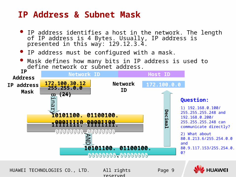
IP Address & Subnet Mask
IP address identifies a host in the network. The length of IP address is 4 Bytes. Usually, IP address is presented in this way: 129.12.3.4.
IP address must be configured with a mask. Mask defines how many bits in IP address is used to define network or
subnet address.
Network ID Host IDIP Address
172.100.30.12172.100.30.12IP addressMask
10101100. 01100100. 00000000.0000000010101100. 01100100. 00000000.00000000
Decim
alD
ecimal
255.255.0.0 (24)255.255.0.0 (24)
10101100. 01100100. 00011110.0000110010101100. 01100100. 00011110.00001100
11111111. 11111111. 00000000.0000000011111111. 11111111. 00000000.00000000
Binary
Binary
172.100.0.0Network ID
AN
DA
ND
Question:
1) 192.168.0.100/ 255.255.255.248 and 192.168.0.200/ 255.255.255.248 can communicate directly?
2) What about 80.8.213.6/255.254.0.0 and 80.9.117.153/255.254.0.0?

HUAWEI TECHNOLOGIES CO., LTD. Page 10All rights reserved
Special IP Address
Network ID Host ID Address type Use
AnyCompletely“0”
Network addressRepresenting a network
Segment
AnyCompletely“1”
Broadcast addressAll the nodes of a specially
designated network segment
127 any Loop back address Loop test
Completely“0” Any networksHuawei Quidway router used to Designate default routes
Completely“1” Broadcast addressAll nodes of
Local network segment
Question: Who know how many IP address are reserved for private IP address?

HUAWEI TECHNOLOGIES CO., LTD. Page 11All rights reserved
Why do we plan subnet?
Because of broadcast messages, the service quality will decrease when the number of hosts increases in the network.
When the network is divided into several subnets, the unnecessary communication can be avoided.
There are too many broadcast messages in the network. We have to separate into two subnets.
Network ID:192.168.0.0Subnet Mask:255.255.254.0Broadcast IP:192.168.1.255Available IP range:192.168.0.1~192.168.1.254
Network ID:192.168.0.0Subnet Mask:255.255.255.0Broadcast IP:192.168.0.255Available IP range:192.168.0.1~192.168.0.254
Network ID:192.168.1.0Subnet Mask:255.255.255.0Broadcast IP:192.168.1.255Available IP range:192.168.1.1~192.168.1.254
Router
HUAWEI TECHNOLOGIES CO., LTD. Page 12All rights reserved
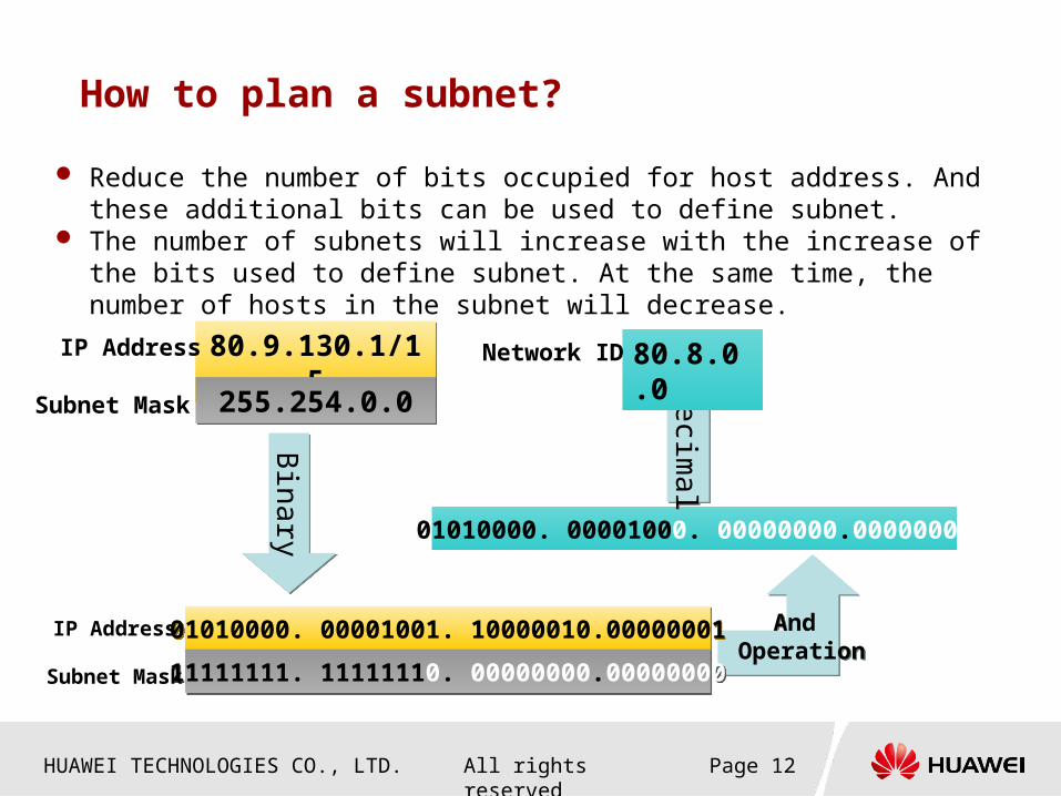
How to plan a subnet?
Reduce the number of bits occupied for host address. And these additional bits can be used to define subnet.
The number of subnets will increase with the increase of the bits used to define subnet. At the same time, the number of hosts in the subnet will decrease.
80.9.130.1/1580.9.130.1/15IP Address
Subnet Mask
And Operation
And Operation
01010000. 00001000. 00000000.00000000
De
cimal
De
cimal
255.254.0.0255.254.0.0
01010000. 00001001. 10000010.0000000101010000. 00001001. 10000010.00000001
11111111. 11111110. 00000000.0000000011111111. 11111110. 00000000.00000000
Bina
ryB
inary
80.8.0.0Network ID
IP Address
Subnet Mask

HUAWEI TECHNOLOGIES CO., LTD. Page 13All rights reserved
An Example of Subnet Planning
The IP addresses of Class B in the network segment 191.38.0.0/16 are allocated to Company A. The company can plan the subnet for each department in the company.
The company consists of 35 departments, and the host number of each department ranges between 100 to 800.
First, we shall define how many bits could be occupied by Host ID. In this case ,the number of hosts are less than 1000. So, 10 bits are enough to be reserved for Host ID. And the number of available Hosts are 2^10 - 2= 1022>1000.
The remaining bits could be used for Network ID now. In this case, 6 bits remains. So the number of subnets are 2^6 = 64, and the subnet mask is: 255.255.252.0.
To summarize, each department now occupies a network segment as below.
Department ID Subnet ID Network Segment
0 191.38.0.0 191.38.0.1~191.38.3.254
1 191.38.4.0 191.38.4.1~191.38.7.254
2 191.38.8.0 191.38.8.1~191.38.11.254
….. …… ……
63 191.38.252.0 191.38.252.1~191.38.255.254
Any simple way to finish this?

HUAWEI TECHNOLOGIES CO., LTD. Page 14All rights reserved
Router and its Function
Routers are used for network interconnection. Routers must have:
Two interfaces or more Protocols reaching network layer at least Storing, forwarding and routing function
Routers core function is to implement network interconnection Forward packets Route (routing): create, refresh and search routing table Rate match between networks Isolate network, prevent network storm, designate access rule (firewall) Interconnect dissimilar network
Routing is shown as below:
Destination Subnet Subnet Mask Next Hop Address
0.0.0.0 0.0.0.0 10.0.0.1
100.0.0.0 255.255.255.0 20.0.0.1
200.0.0.0 255.255.255.0 30.0.0.1
HUAWEI TECHNOLOGIES CO., LTD. Page 15All rights reserved
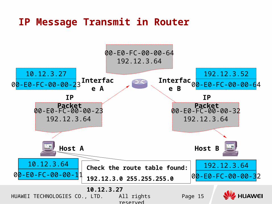
IP Message Transmit in Router
10.12.3.64
00-E0-FC-00-00-11192.12.3.64
00-E0-FC-00-00-32
192.12.3.52
00-E0-FC-00-00-64
10.12.3.27
00-E0-FC-00-00-23
00-E0-FC-00-00-23192.12.3.64
00-E0-FC-00-00-64192.12.3.64
00-E0-FC-00-00-32192.12.3.64
Interface A Interface B
Host A Host B
IP Packet
Check the route table found:
192.12.3.0 255.255.255.0 10.12.3.27
IP Packet

HUAWEI TECHNOLOGIES CO., LTD. Page 16All rights reserved
NAT
Question: How does Private IP access internet?
1. Even if we can configure outgoing route for the private IP address, but there is no return route for it in internet, so private IP address cannot access internet by route configuration. How does Private IP access internet?2. NAT function can implement below translation: <Private address+Port>←→<Public address+Port>. Then the private IP address can access internet.

HUAWEI TECHNOLOGIES CO., LTD. Page 17All rights reserved
Dynamic Routing
20 bytes IP header8 bytes UDP header
RIP message
8-bit command (1-6)
8-bit version (1)
16-bit all 0
16-bit address family(2)
16-bit all 0
32-bit IP address
32-bit all 0
32-bit all 0
32-bit metric (1-16)
Up to 24more routes, with same format as previous 20 bytes
OSPF (Open Shortest Path First )
RIP (Routing Information Protocol )
OSPF is a newer alternative to RIP. OSPF is a link-state protocol, In a link-state protocol a router does not exchange distances with its neighbors. Instead each router actively tests the status of its link to each of its neighbors, sends this information to its other neighbors, which then propagate it throughout the autonomous system. Each router takes this link-state information and builds a complete routing table. Besides being a link-state protocol instead of a distance-vector protocol, OSPF has many other features that make it superior to RIP. With most router vendors supporting OSPF, it will start replacing RIP in many networks.
RIP is a distance-vector protocol. The term distance-vector means the messages sent by RIP contain a vector of distances (hop counts). Each router updates its routing table based on the vector of these distances that it receives from its neighbors.

HUAWEI TECHNOLOGIES CO., LTD. Page 18All rights reserved
VRRP (Virtual Router Redundancy Protocol)
Virtual IP Address10.100.10.1
Network
Host 1 Host 3Host 2
10.100.10.2 10.100.10.3
Master Backup
LAN 1
RouerA RouterB
Ethernet
10.100.10.1 10.100.10.1 10.100.10.1
Ethernet
10.100.10.1
Network
Host 1 Host 3Host 2
LAN 110.100.10.1
10.100.10.1 10.100.10.1
RouterA
Use VRRP is more safe

HUAWEI TECHNOLOGIES CO., LTD. Page 19All rights reserved
Chapter 1 Basic KnowledgeChapter 1 Basic Knowledge
Chapter 2 Protocol StackChapter 2 Protocol Stack
Chapter 3 IP Address in CBSSChapter 3 IP Address in CBSS

HUAWEI TECHNOLOGIES CO., LTD. Page 20All rights reserved
CDMA2000 1X Protocol Stack
Air
L3 Sig.
LAC
MAC
Air
MAC
User TrafficFrame
Abis Sig.
L3 Sig.
TCP
IP
AAL5
ATM
E1/SDH0
Abis Traffic
AAL2
ATM
User TrafficFrame
E1/SDH0
A7
L3 Sig.
TCP
IP
AAL5
ATM
E1/SDH0
A3 Sig.
L3 Sig.
TCP
IP
AAL5
ATM
AAL2
ATM
User TrafficFrame
E1/SDH0
E1/SDH0
A11
L3 Sig.
UDP
Ethernet
IP
A10
GRE
IP
SDH0/FE
DataPacket
Ethernet
A1
L3 Sig.
SCCP
MTP3
MTP2
MTP1
E1/SDH0
A2
PCM/UDI
E1/SDH0
VoiceFrame
DataPacket
L3 Sig.
IPC
A9
A8
UoIP
GE
GE
Phys. Layer
Phys. Layer
A1p
L3 Sig.
SCCP
IP
Phys. Layer
A5
PCM/UDI
E1/SDH0
CircuitSwitch Data
ISLP
A2p
UDP
Phys. Layer
VoiceFrame
IPv4
Abis Sig.
L3 Sig.
TCP
IP
E1/FE
Abis Traffic
User TrafficFrame
E1/FE
UDP
IP
Link Layer
Link Layer
M3UA
SCTP/SUA
A7/A3 Sig.
L3 Sig.
SCTP
IP
E1/SDH0
A3 Traffic
User TrafficFrame
E1/FE
UDP
IP
Link Layer
Link Layer
A3 Traffic
SDH0/FE
Ethernet
Ethernet

HUAWEI TECHNOLOGIES CO., LTD. Page 21All rights reserved
CDMA2000 1X EVDO Protocol StackAir
Application Layer
Session
Connection
Security
MAC
Air
MAC
User TrafficFrame
Abis Sig.
L3 Sig.
TCP
IP
AAL5
ATM
E1/SDH0
Abis Traffic
AAL2
ATM
User TrafficFrame
E1/SDH0
A12
L3 Sig.
UDP
IP
SDH0
Ethernet
A13
L3 Sig.
TCP/UDP
IP
E1/FE/SDH0
Link Layer
Stream Layer
Session
Connection
Security
Stream Layer
RLP
A16
L3 Sig.
UDP
IP
A11
L3 Sig.
UDP
Ethernet
IP
A10
GRE
IP
SDH0/FE
Data Packet
Ethernet
Data Packet
L3 Sig.
IPC
A9
A8
UoIP
GE
GE SDH0/FE
Ethernet
Ethernet
Link Layer
E1/FE/SDH0
Abis Sig.
L3 Sig.
TCP
IP
E1/FE
Abis Traffic
User TrafficFrame
E1/FE
UDP
IP
Link Layer
Link Layer

HUAWEI TECHNOLOGIES CO., LTD. Page 22All rights reserved
Chapter 1 Basic KnowledgeChapter 1 Basic Knowledge
Chapter 2 Protocol StackChapter 2 Protocol Stack
Chapter 3 IP Address in CBSSChapter 3 IP Address in CBSS

HUAWEI TECHNOLOGIES CO., LTD. Page 23All rights reserved
IP plan of Abis interface (ATM)
80.0.0.255/NetMask 255.0.0.0
129.11.95.25480.170.19.64
BCIM
BCKM
SCUO
SPUO
AEUB/AOUB
BAM
OMU
O&M Link
Signaling Link
ATM Link
80.146.16.192
80.144.16.64
129.8.192.880.126.130.116
About BTS OM link:BSCside 80.0.0.255-----129.8.192.8 BTS sideADD BTSOMLNK, BSC will auto assign BTS OM IP on BTS side, you may use LST BTSLNK to query it. When ADD BTS, we need input this IP, About BTS Signaling link:BSCside 80.144.16.64-----80.126.130.116 BTS sideADD BRD(SPUO subsystem), BSC will auto assign SPUO IP, this is the BTS signaling IP on BSC side, you may use LST SUBSYSTEM to query it. ADD BTSSIGLNK, BSC will auto assign BTS SIG IP on BTS side, you may use LST BTSLNK to query it.When ADD CBTSTERSIGLNK, we need input these “bscip” and “btsip”.About BTS Traffic link:QC51BCIM supports ATMEXCLUSIVE only, each QC51BCIM must configure a traffic link;
QC52BCIM supports ATMSHARED and ATMEXCLUSIVE traffic link, we may configure a traffic link for multi CCPM ; QC54BCIM supports ATMSHARED, ATMEXCLUSIVE and IPSHARED traffic link.
HUAWEI TECHNOLOGIES CO., LTD. Page 24All rights reserved
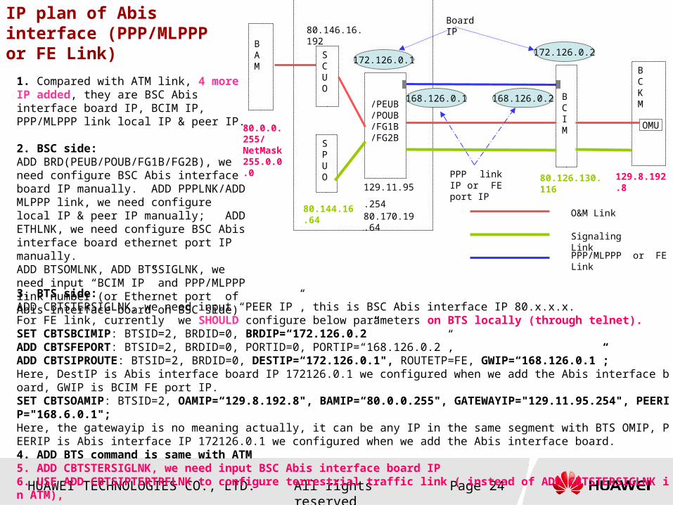
IP plan of Abis interface (PPP/MLPPP or FE Link)
80.126.130.116
80.0.0.255/NetMask 255.0.0.0
129.11.95.254 80.170.19.64
BCIM
BCKM
SCUO
SPUO
/PEUB/POUB/FG1B/FG2B
BAM
OMU
O&M Link
Signaling Link
PPP/MLPPP or FE Link
80.146.16.192
80.144.16.64
172.126.0.1172.126.0.2
Board IP
PPP link IP or FE port IP
129.8.192.8
168.126.0.2168.126.0.1
1. Compared with ATM link, 4 more IP added, they are BSC Abis interface board IP, BCIM IP, PPP/MLPPP link local IP & peer IP.
2. BSC side:ADD BRD(PEUB/POUB/FG1B/FG2B), we need configure BSC Abis interface board IP manually. ADD PPPLNK/ADD MLPPP link, we need configure local IP & peer IP manually; ADD ETHLNK, we need configure BSC Abis interface board ethernet port IP manually. ADD BTSOMLNK, ADD BTSSIGLNK, we need input “BCIM IP” and PPP/MLPPP link number (or Ethernet port of Abis interface board on BSC side)
3. BTS side:ADD CBTSTERSIGLNK, we need input “PEER IP”, this is BSC Abis interface IP 80.x.x.x.For FE link, currently we SHOULD configure below parameters on BTS locally (through telnet).SET CBTSBCIMIP: BTSID=2, BRDID=0, BRDIP=“172.126.0.2”ADD CBTSFEPORT: BTSID=2, BRDID=0, PORTID=0, PORTIP=“168.126.0.2”, ADD CBTSIPROUTE: BTSID=2, BRDID=0, DESTIP=“172.126.0.1", ROUTETP=FE, GWIP=“168.126.0.1”;Here, DestIP is Abis interface board IP 172126.0.1 we configured when we add the Abis interface board, GWIP is BCIM FE port IP.SET CBTSOAMIP: BTSID=2, OAMIP=“129.8.192.8", BAMIP=“80.0.0.255", GATEWAYIP="129.11.95.254", PEERIP="168.6.0.1";Here, the gatewayip is no meaning actually, it can be any IP in the same segment with BTS OMIP, PEERIP is Abis interface IP 172126.0.1 we configured when we add the Abis interface board.4. ADD BTS command is same with ATM5. ADD CBTSTERSIGLNK, we need input BSC Abis interface board IP6. USE ADD CBTSIPTERTRFLNK to configure terrestrial traffic link ( instead of ADD CBTSTERSIGLNK in ATM),

HUAWEI TECHNOLOGIES CO., LTD. Page 25All rights reserved
O&M IP between BSC6680 and BTS
IP Address Description
IP address of the Abis interface board
80.a.b.c & 129.j.k.254The values a, b, and c are determined by the type, subrack number, and slot number of the interface board, they are automatically generated by the system.
IP address used for BTS O&M
129.m.n.lThe variant m is related to the subrack number and the slot number of the interface board of the BTS. The variant n is related to the number of the BTS and the slot number of the interface board of the BTS. The variant l is related to the number of the BTS. The variants m, n, and l are automatically generated by the system.

HUAWEI TECHNOLOGIES CO., LTD. Page 26All rights reserved
Signaling IP between BSC6680 and BTS
80.126.f.l
80.126.0.0
BTS
TCP/IP
BTS
BTS
BTS
80.126.f.l
80.126.f.l
80.126.f.lBSC6680
SPUO
80.144.a.b
IP Address Description
IP address of the SPUO subsystem
80.144.a.bThe subnet mask is 255.0.0.0. The variant a is related to the number of the subrack where the SPUO subsystem is located. The variant b is related to the number of the slot where the SPUO subsystem is located.
IP address of the BTS for signaling transmission
80.126/127.f.l ,The subnet mask is 255.0.0.0. The variant f is equal to the highest five bits of the BTS number. The variant l is equal to the lowest eight bits of the BTS number. The signaling IP address of the BTS that is configured on the second SPUO subsystems is 80.127.f.l.
HUAWEI TECHNOLOGIES CO., LTD. Page 27All rights reserved
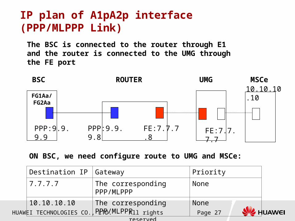
IP plan of A1pA2p interface (PPP/MLPPP Link)
FG1Aa/FG2Aa
PPP:9.9.9.9 PPP:9.9.9.8
UMGBSC
FE:7.7.7.8
ROUTER
FE:7.7.7.7
The BSC is connected to the router through E1 and the router is connected to the UMG through the FE port
Destination IP Gateway Priority
7.7.7.7 The corresponding PPP/MLPPP None
10.10.10.10 The corresponding PPP/MLPPP None
ON BSC, we need configure route to UMG and MSCe:
10.10.10.10MSCe
HUAWEI TECHNOLOGIES CO., LTD. Page 28All rights reserved
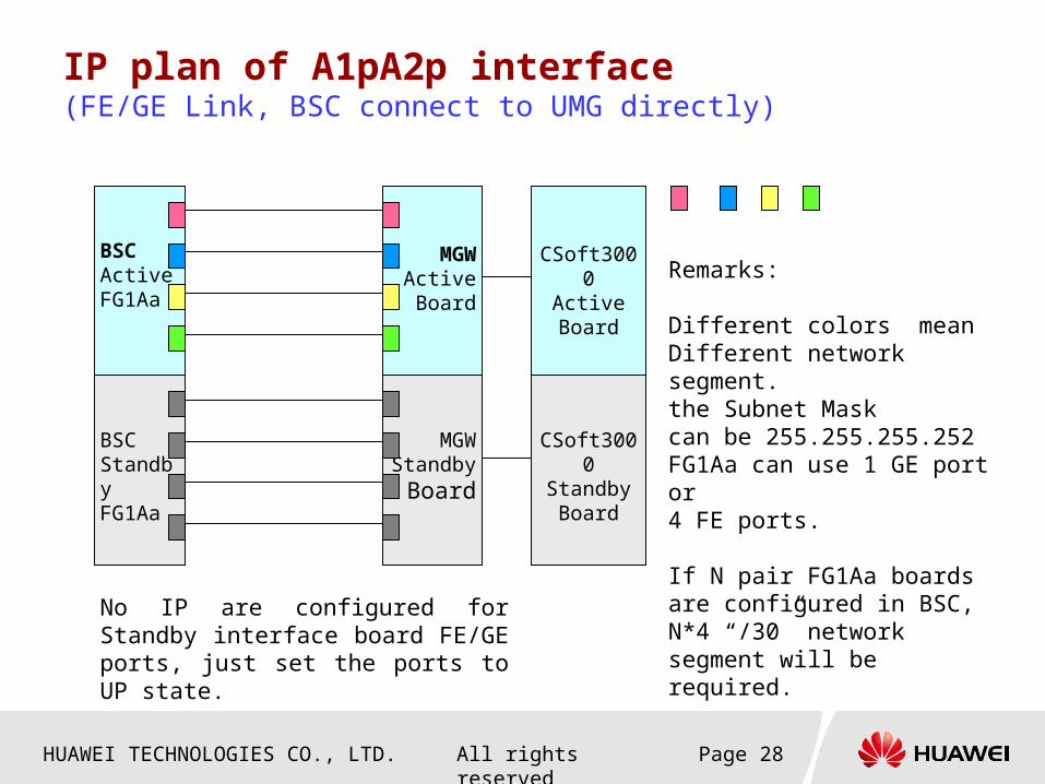
IP plan of A1pA2p interface (FE/GE Link, BSC connect to UMG directly)
BSCActive FG1Aa
MGW ActiveBoard
No IP are configured for Standby interface board FE/GE ports, just set the ports to UP state.
BSCStandby FG1Aa
MGW Standby
Board
Remarks:
Different colors meanDifferent network segment.the Subnet Maskcan be 255.255.255.252FG1Aa can use 1 GE port or4 FE ports.
If N pair FG1Aa boards are configured in BSC, N*4 “/30” network segment will be required.
CSoft3000ActiveBoard
CSoft3000Standby Board
HUAWEI TECHNOLOGIES CO., LTD. Page 29All rights reserved
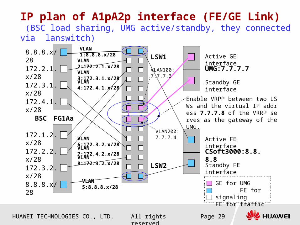
IP plan of A1pA2p interface (FE/GE Link) (BSC load sharing, UMG active/standby, they connected via lanswitch)
8.8.8.x/28Active GE interface
Standby GE interface
Enable VRPP between two LSWs and the virtual IP address 7.7.7.8 of the VRRP serves as the gateway of the UMG.
LSW1
BSC
UMG:7.7.7.7172.2.1.x/28
172.3.1.x/28
172.4.1.x/28
172.1.2.x/28
172.2.2.x/28
172.3.2.x/28
8.8.8.x/28
VLAN 1:8.8.8.x/28
VLAN 2:172.2.1.x/28
VLAN 3:172.3.1.x/28
VLAN 4:172.4.1.x/28
VLAN 8:172.3.2.x/28
VLAN 5:8.8.8.x/28
VLAN 6:172.3.2.x/28
VLAN 7:172.4.2.x/28
FG1Aa
VLAN200: 7.7.7.4
VLAN100: 7.7.7.3
Active FE interface
Standby FE interface
CSoft3000:8.8.8.8
LSW2
GE for UMG FE for signaling FE for traffic
HUAWEI TECHNOLOGIES CO., LTD. Page 30All rights reserved
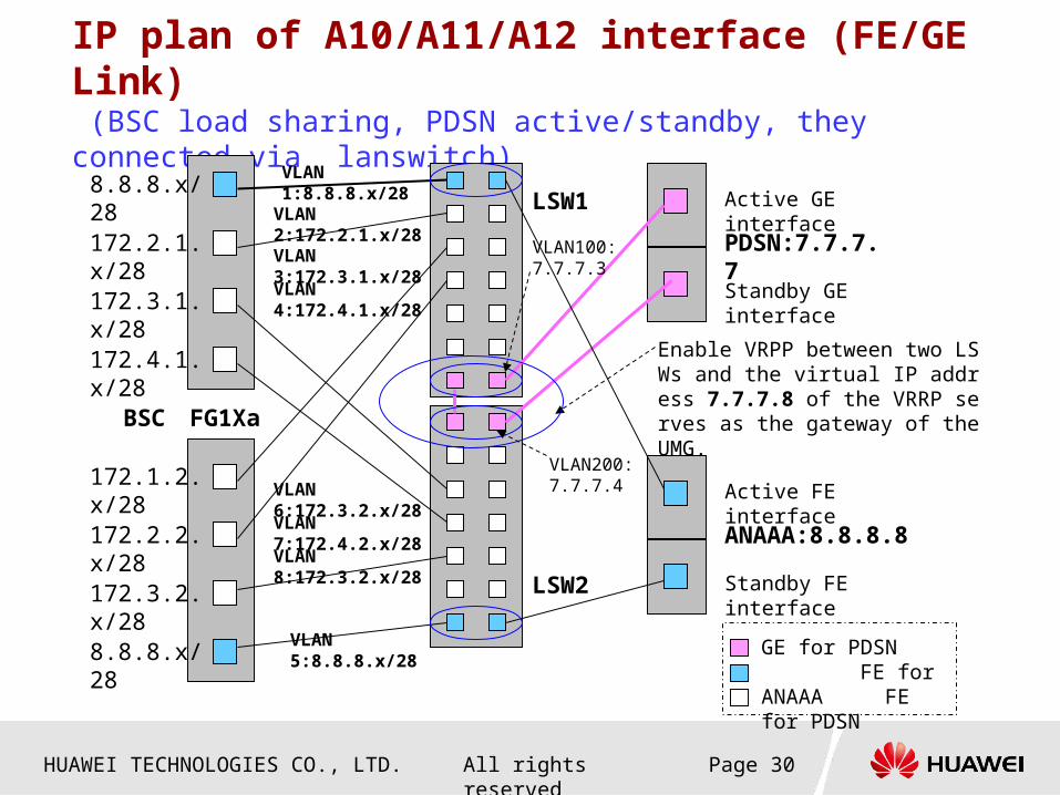
IP plan of A10/A11/A12 interface (FE/GE Link) (BSC load sharing, PDSN active/standby, they connected via lanswitch)
8.8.8.x/28Active GE interface
Standby GE interface
Enable VRPP between two LSWs and the virtual IP address 7.7.7.8 of the VRRP serves as the gateway of the UMG.
LSW1
BSC
PDSN:7.7.7.7172.2.1.x/28
172.3.1.x/28
172.4.1.x/28
172.1.2.x/28
172.2.2.x/28
172.3.2.x/28
8.8.8.x/28
VLAN 1:8.8.8.x/28
VLAN 2:172.2.1.x/28
VLAN 3:172.3.1.x/28
VLAN 4:172.4.1.x/28
VLAN 8:172.3.2.x/28
VLAN 5:8.8.8.x/28
VLAN 6:172.3.2.x/28
VLAN 7:172.4.2.x/28
FG1Xa
VLAN200: 7.7.7.4
VLAN100: 7.7.7.3
Active FE interface
Standby FE interface
ANAAA:8.8.8.8
LSW2
GE for PDSN FE for ANAAA FE for PDSN

HUAWEI TECHNOLOGIES CO., LTD. Page 31All rights reserved
IP plan of A3/A7/A13/A16 interface (FE/GE Link) (BSC interface board active/standby)
FE/GEFE/GE
IP Network
Router 1 Router 2VRRP
BSC3
FG1B
FG1B
StandbyActive
FG1B
FG1B
BSC2
BSC1
Active Standby
BSC IP: 192.168.0.1
BSC IP: 192.168.0.2
BSC IP: 192.168.0.3

HUAWEI TECHNOLOGIES CO., LTD. Page 32All rights reserved
IP Address for O & M
BAM 0
BTS (OMU
)
BTS (OMU
)
BTS (OMU
)
BAM 1
M2000 Server
80.0.0.255/8 80.0.0.252/8
WS WS WS
A1.A2.A3.A4/B A1.A2.A3.A4/B A1.A2.A3.A4/B A1.A2.A3.A4/B
A1.A2.A3.A4/B A1.A2.A3.A4/B
129.m.n.l/8
This subnet is involved in operation and maintenance system. All equipment in LAN must be in the same IP segment .The operator shall plan its IP address by itself. Private or public IP address can be used.
This subnet realizes the interconnection between the BAM/EWS and BSC, and between BSC boards. Every IP address is fixed. It occupies 80.0.0.0/8 network segment.
SCUOa
SCUOa
Abis boar
d
Other
board
Other
board
Abisboar
d
CMPS CSPS
BTS (OMU
)
BTS (OMU
)
BTS (OMU
)129.m.n.l/8
80.130.16.192/8 80.130.24.192/8
80.x.x.x/8 80.x.x.x/8
This subnet realizes BTS OM link. Every IP address is fixed. It occupies 129.0.0.0/8 network segment.

HUAWEI TECHNOLOGIES CO., LTD. Page 33All rights reserved
IP Address Requirement is BSC(1) Parameter Remarks
BSC IP
1. When A3A7 interface is ATM, neighbour IP must be in the same segment;2. After BScV200R003, the BSC IP is not necessary in the same segment with PCF IP.
PCF IP
1. PCF IP is a logical IP. More than one PCF can be configured in one BSC.2. After BScV200R003, the BSC IP is not necessary in the same segment with PCF IP.3. PCF IP and PCF interface board port IP cannot be in the same segment
Logic IP (board IP) of FG1B/FG2BWhen Abis interface is IP over FE, Logical IP of Abis interface Board must use public IP.
Logic IP (board IP) of BCIM (IP over FE) FE/GE A interface board (FG1A/FG2A) Ethernet port IP 1. Different Ethernet port IP on one board must be in different
network segment, It's better that all ethernet ports on all boards are in different segment.2. Min. required network segment No.=Ethernet ports used on each board, Max. required network segment No. =All ethernet ports used on all board
FE/GE A10/A11 interface board (FG1B/FG2B/FG1X/FG2X/GOUX) Ethernet port IP
FE/GE A3/A7 interface board (FG1B/FG2B) Ethernet port IP
FE/GE Abis interface board (FG1B/FG2B) Ethernet port IP
FE port IP of BCIM(IP over FE)
PPP/MLPPP link IP for PEUABecause there is no logical IP of A interface board after BSCV200R002, this PPP local end IP must be configured in MSCe, so it is visible outside BSC and need be planned.

HUAWEI TECHNOLOGIES CO., LTD. Page 34All rights reserved
IP Address Requirement is CBSS(2)
Parameter RemarksO&M IP Virtual external IP of BAM/EWS Communicate with M2000 and LMT
LMT n
M2000 server IP
M2000 Dial Access Server
M2000 client n
BTS OM IPOccupy 129.x.x.x segment. System distribute automatically 。 This segment can not be the same as other inter network of BSC 。
BTS signaling IPOccupy 80.x.x.x segment 。 System distribute automatically 。 This segment can not be the same as other inter network of BSC 。
Logic IP (board IP) of Abis interface board PEUB/POUB(IP over E1)
When Abis adopts IP over E1, logical IP of PEUB/POUB is visible in BSC and BTS only.
Logic IP (board IP) of BCIM board (IP over E1)When Abis adopts IP over E1, logical IP of BCIM is visible in BSC and BTS only.
PPP/MLPPP link IP of Abis interface and A3/A7 interface
1. Local IP and peer IP of PPP/MLPPP link can be in different segment;2. Local IP and peer IP of different PPP/MLPPP link must be different.3. When Abis/A3A7 adopts IP over E1, PPP/ML PPP link is visible in BSC and BTS only.
Virtual internal IP of BAM/EWS
Remarks: Yellow field means must negotiated with operator, green field means may use private IP

www.huawei.com
Thank You


