55
Jan Doris C. Latada , ECE Holy Cross of Davao College, Inc.

7/21/2019 03_AM Transmission and Reception
http://slidepdf.com/reader/full/03am-transmission-and-reception 1/55
Jan Doris C. Latada , ECE
Holy Cross of Davao College, Inc.

7/21/2019 03_AM Transmission and Reception
http://slidepdf.com/reader/full/03am-transmission-and-reception 2/55
AM Transmission
Low-Level DSBFC AM Tx1
2
3
High-Level DSBFC AM Tx
Carrier Shift

7/21/2019 03_AM Transmission and Reception
http://slidepdf.com/reader/full/03am-transmission-and-reception 3/55
Block Diagram of Low-Level AM
DSBFC Tx

7/21/2019 03_AM Transmission and Reception
http://slidepdf.com/reader/full/03am-transmission-and-reception 4/55
MODULATING SIGNAL: acoustical transducers
(microphone, magnetic tape, cd or phonograph
record)
PRE-AMP: a sensitive class A linear voltage amplifier
with high input impedance. Use to raise the
amplitude of the source signal to a usable level whileproducing minimum nonlinear distortion.
MODULATING SIGNAL DRIVER: a linear amplifier
used to amplify the information signal to an
adequate level to sufficiently drive the modulator.
RF Carrier OSCILLATOR: common used is the crystal-
controlled oscillator for accuracy and stability.

7/21/2019 03_AM Transmission and Reception
http://slidepdf.com/reader/full/03am-transmission-and-reception 5/55
BUFFER AMPLIFIER: a low-gain, high-input impedance
linear amplifier used to isolate the oscillator from the
high-power amplifier. Also provides a relatively constantload to the oscillator that reduces the occurrence and
magnitude of short-term frequency variations. (usually
emitter follower of IC op-amp)
MODULATOR: modulation takes place
INTERMEDIATE AND FINAL POWER AMPLIFIERS: either
class A or B push-pull modulators to maintain symmetry
in the AM envelope. COUPLING NETWORK: used for impedance matching of
the final power amp and the transmission line and
antenna.
7/21/2019 03_AM Transmission and Reception
http://slidepdf.com/reader/full/03am-transmission-and-reception 6/55
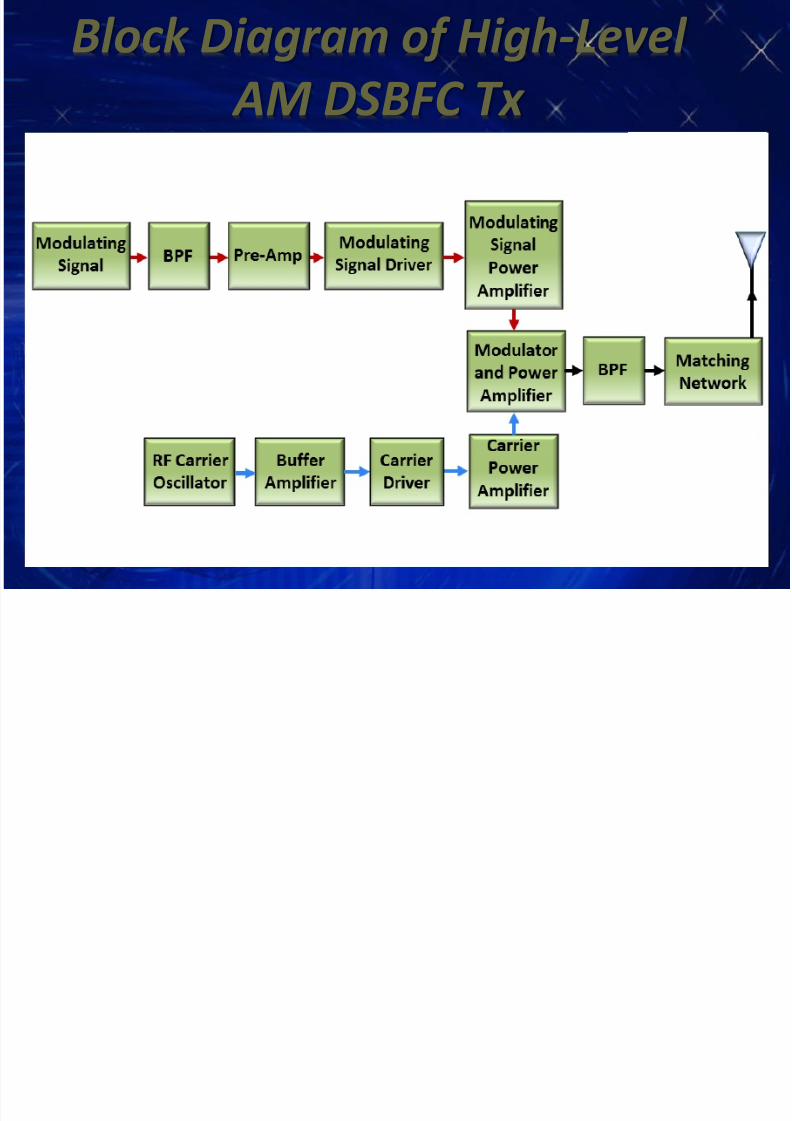
Block Diagram of High-Level
AM DSBFC Tx

7/21/2019 03_AM Transmission and Reception
http://slidepdf.com/reader/full/03am-transmission-and-reception 7/55
MODULATING SIGNAL & CARRIER: processed in the
same manner as in the low-level Tx in addition of
power amplifier.
HIGH LEVEL TX: The modulating signal and carrier
undergoes additional power amplification prior to
modulator stage to obtain 100% modulation. MODULATOR: serves as the final power amplifier,
usually a drain-, plate, or collector-modulated class C
amplifier. Function, (1) modulation circuit (2) class C
power amplifier for efficiency, (3) frequency up-
converter (translates the LF signal to RF signals to be
efficiently radiated from an antenna.)
7/21/2019 03_AM Transmission and Reception
http://slidepdf.com/reader/full/03am-transmission-and-reception 8/55
Carrier Shift
Sometimes called upward or downward
modulation.
A form of amplitude distortion introduced
when positive and negative alternations in theAM signals are not equal (i.e. non-symmetrical
modulation).
May be either positive or negative.
It is an indication of the average voltage of
an AM modulated signals.
7/21/2019 03_AM Transmission and Reception
http://slidepdf.com/reader/full/03am-transmission-and-reception 9/55
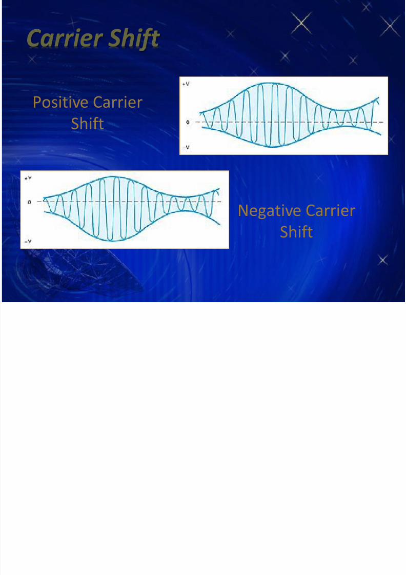
Carrier Shift
Positive Carrier
Shift
Negative CarrierShift

7/21/2019 03_AM Transmission and Reception
http://slidepdf.com/reader/full/03am-transmission-and-reception 10/55
AM Reception
Block Diagram of Simple Rx1
2
3
4
Receiver Parameters
DSBFC Receivers
DSBFC Receiver Operations

7/21/2019 03_AM Transmission and Reception
http://slidepdf.com/reader/full/03am-transmission-and-reception 11/55
AM Reception
A receiver must able to:
receive, amplify and demodulate an AM wave.
It must also be capable of “bandlimiting” the
total RF spectrum to a specific desired band of
frequencies. The selection process calledTUNING the receiver.

7/21/2019 03_AM Transmission and Reception
http://slidepdf.com/reader/full/03am-transmission-and-reception 12/55
Block Diagram of Simple AM Rx

7/21/2019 03_AM Transmission and Reception
http://slidepdf.com/reader/full/03am-transmission-and-reception 13/55
AM Demodulation
RF SECTION: the first stage of the receiver. Aka
receiver front end. Its function are detecting,
bandlimiting, and amplifying the received RF signals.
MIXER/CONVERTER: down converts the received RFfrequencies to intermediate frequencies (IFs)
IF SECTION: amplification and selectivity
AM DETECTOR: demodulates the AM wave andconverts it to the original information.
AUDIO SECTION: amplifies the recovered information

7/21/2019 03_AM Transmission and Reception
http://slidepdf.com/reader/full/03am-transmission-and-reception 14/55
Receiver Parameters
Selectivity
Bandwidth Improvement
Sensitivity
Dynamic Range
Shape Factor
Fidelity
Insertion Loss

7/21/2019 03_AM Transmission and Reception
http://slidepdf.com/reader/full/03am-transmission-and-reception 15/55
Receiver Parameters
SelectivityUsed to measure the ability of the receiver to
accept a given band of frequencies and reject
all others.
It is the degree of distinction made by the
receiver between the desired signal and
unwanted signals.Example:
commercial AM, BW = 10kHz; the receiver must limit
its BW to 10kHz.

7/21/2019 03_AM Transmission and Reception
http://slidepdf.com/reader/full/03am-transmission-and-reception 16/55
Receiver Parameters
Selectivity
EXAMPLE:
A TRF receiver is to be designed with a single tuned
circuit using a 10µH inductor. Calculate the capacitance
range of the variable capacitor required to cover the
entire AM band (535-1605 kHz) and also calculate the
bandwidth at 540 kHz and 1600 kHz (assume Q = 110)
=
Where: fr = resonant frequency in Hz
=
2
7/21/2019 03_AM Transmission and Reception
http://slidepdf.com/reader/full/03am-transmission-and-reception 17/55
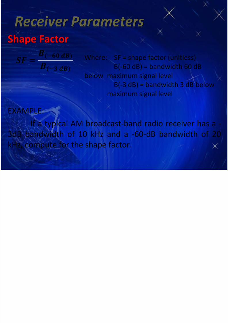
Receiver Parameters
Shape Factor
EXAMPLE:
If a typical AM broadcast-band radio receiver has a -
3dB bandwidth of 10 kHz and a -60-dB bandwidth of 20
kHz, compute for the shape factor.
=(− )
(− )
Where: SF = shape factor (unitless)
B(-60 dB) = bandwidth 60 dB
below maximum signal level
B(-3 dB) = bandwidth 3 dB below
maximum signal level

7/21/2019 03_AM Transmission and Reception
http://slidepdf.com/reader/full/03am-transmission-and-reception 18/55
Receiver Parameters
Bandwidth ImprovementDecreasing the BW reduces the noise by the
same proportion, thus increasing the S/N ratio
improving the system performance.
Where: BI = bandwidth improvementBRF = RF bandwidth (Hz)
BIF = IF bandwidth (Hz)
=

7/21/2019 03_AM Transmission and Reception
http://slidepdf.com/reader/full/03am-transmission-and-reception 19/55
Receiver Parameters
Noise Figure Improvementthe corresponding reduction in noise figure
due to the reduction in bandwidth
EXAMPLE:
Determine the improvement in the noise figure for a
receiver with an RF bandwidth equal to 200 kHz and an IF
bandwidth equal to 10 kHz.
=

7/21/2019 03_AM Transmission and Reception
http://slidepdf.com/reader/full/03am-transmission-and-reception 20/55
Receiver Parameters
SensitivityThe minimum RF signal that can be detected
receiver input and still produce a usable
demodulated information signal.
It is the ability of a receiver to reproduce
weak signals expressed in µV. Also called receiver
threshold.Typical Values (commercial AM):
S/N ratio – 10dB
Power output – 1/2W (27dBm)

7/21/2019 03_AM Transmission and Reception
http://slidepdf.com/reader/full/03am-transmission-and-reception 21/55
Receiver Parameters
SensitivityTypical sensitivity for commercial AM is 50μV.
Factors:
– Noise power at the input – Noise Figure
– Sensitivity of the AM detector
– Bandwidth improvement factorNOTE:
The best way to improve the sensitivity of a Rx is
to reduce the noise level.

7/21/2019 03_AM Transmission and Reception
http://slidepdf.com/reader/full/03am-transmission-and-reception 22/55
Receiver Parameters
Dynamic Range
The input power range over which the
receiver is useful.
The difference in dB between the minimum
input level necessary to discern a signal and the
input level that will overdrive the receiver and
produce distortion.
= ( )
()
= ( )
()

7/21/2019 03_AM Transmission and Reception
http://slidepdf.com/reader/full/03am-transmission-and-reception 23/55
Receiver Parameters
Dynamic Range
EXAMPLE:
A receiver has a dynamic range of 90 dB. It
has 1.5 nW sensitivity (threshold). Determine the
maximum allowable input signal.

7/21/2019 03_AM Transmission and Reception
http://slidepdf.com/reader/full/03am-transmission-and-reception 24/55
Receiver Parameters
Fidelity
The ability of a communications system to
produce an exact replica of the original source
information.
Any frequency, phase, or amplitude
variations that are present in the demodulated
waveform that were not in the originalinformation signal are considered distortion.

7/21/2019 03_AM Transmission and Reception
http://slidepdf.com/reader/full/03am-transmission-and-reception 25/55
Receiver Parameters
Distortions: Phase distortion
– is not particularly important for voice transmission but can be
devastating to data transmissions.
Amplitude distortion
– occurs when the Amplitude-vs-Frequency characteristics of a
signal at the output of a receiver differ from those of the
original information signal.
– Result of non-uniform gain in amplifiers and filters.
Frequency distortion
– result of harmonic and intermodulation distortion caused by
nonlinear amplification
7/21/2019 03_AM Transmission and Reception
http://slidepdf.com/reader/full/03am-transmission-and-reception 26/55
Receiver Parameters
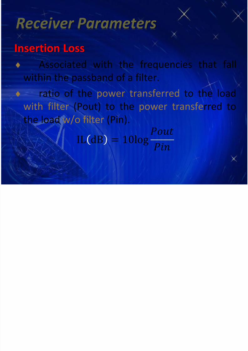
Insertion Loss
Associated with the frequencies that fall
within the passband of a filter.
ratio of the power transferred to the load
with filter (Pout) to the power transferred to
the load w/o filter (Pin).
IL dB = 10log

7/21/2019 03_AM Transmission and Reception
http://slidepdf.com/reader/full/03am-transmission-and-reception 27/55
DSBFC Receivers
Tuned Radio-Frequency (TRF) Receiver
Superheterodyne Receiver

7/21/2019 03_AM Transmission and Reception
http://slidepdf.com/reader/full/03am-transmission-and-reception 28/55
DSBFC Receivers
Tuned Radio-Frequency (TRF) RxThe earliest and simplest design radio receiver
used in single-channel LF applications.
Ganged capacitors

7/21/2019 03_AM Transmission and Reception
http://slidepdf.com/reader/full/03am-transmission-and-reception 29/55
DSBFC Receivers
Tuned Radio-Frequency (TRF) Rx
RF STAGE: 2 or 3 RF amplifier are required to
filter an amplify the received signals to a level
sufficient to drive the detector. Integrated with
transformer-coupled tank circuits
DETECTOR: converts RF signals directly to
information.
AUDIO STAGE: amplifies the information signals
to a usable level

7/21/2019 03_AM Transmission and Reception
http://slidepdf.com/reader/full/03am-transmission-and-reception 30/55
DSBFC Receivers
Tuned Radio-Frequency (TRF) Rx
Advantages
Simple
High sensitivity
NOTE:
TRF Rx are seldom used, except for special-purpose single
station Rx.

7/21/2019 03_AM Transmission and Reception
http://slidepdf.com/reader/full/03am-transmission-and-reception 31/55
DSBFC Receivers
Tuned Radio-Frequency (TRF) RxDisadvantages
Tracking errors – capacitances in the cascaded RF
amplifiers will always have differences in value no matter
how small, and this will affect the resonant frequency.
Inconsistent Bandwidth, resulting to poor Selectivity -
Caused by Skin Effect.
– @ high Frequencies, current flow is limited to the surface of theconductor.
– This reduces the effective area (A), and increases resistance (R),
and decreases Quality Factor (Q), thus affecting Selectivity.

7/21/2019 03_AM Transmission and Reception
http://slidepdf.com/reader/full/03am-transmission-and-reception 32/55
DSBFC Receivers
Superheterodyne Receiver Widely used because of its gain, selectivity and
sensitivity characteristics.
invented by Major Edward Armstrong down converts the incoming RF signal to IF
signal before processing and before the
extraction of the information signal
NOTE:
“ Heterodyning” means mixing two frequencies in a
nonlinear device or translate one frequency to
another using nonlinear mixing.

7/21/2019 03_AM Transmission and Reception
http://slidepdf.com/reader/full/03am-transmission-and-reception 33/55
DSBFC Receivers
Superheterodyne Receiver

7/21/2019 03_AM Transmission and Reception
http://slidepdf.com/reader/full/03am-transmission-and-reception 34/55
DSBFC Receivers
Superheterodyne ReceiverPreselector:
a broad-tuned BPF withan adjustable centerfrequency
Provide enough initial bandlimiting to prevent aspecific unwanted RF called the image frequencyfrom entering the receiver.
Reduces the noise BW to the minimum level.
7/21/2019 03_AM Transmission and Reception
http://slidepdf.com/reader/full/03am-transmission-and-reception 35/55
DSBFC Receivers
Superheterodyne ReceiverRF Amplifier:
Determines the sensitivity of the receiver.
Is the primary contributor of noiseOffers several advantages:greater gain, thus better selectivity
improved image-frequency rejection
better S/N ratio
better selectivity.

7/21/2019 03_AM Transmission and Reception
http://slidepdf.com/reader/full/03am-transmission-and-reception 36/55
DSBFC Receivers
Superheterodyne Receiver

7/21/2019 03_AM Transmission and Reception
http://slidepdf.com/reader/full/03am-transmission-and-reception 37/55
DSBFC ReceiversSuperheterodyne Receiver
Local Oscillator:
Linked to the preselector so that it
varies with the carrier frequency.Mixer/Converter:
A nonlinear device in which
heterodyning takes place
converts RF to IF frequencies.
Note:
Common IF in AM broadcast-band Rx
is 455kHz.

7/21/2019 03_AM Transmission and Reception
http://slidepdf.com/reader/full/03am-transmission-and-reception 38/55
DSBFC Receiver Operations
During the demodulation process in theSuperheterodyne receiver:
– The RF is converted to IF (frequency conversion)
– IF is converted to the source information
Intermediate Frequency (IF)
– a frequency to which a carrier frequency is shifted as
an intermediate step in transmission or reception
– created by mixing the carrier signal with a local
oscillator signal in a process called heterodyning,
resulting in a signal at the difference or beat
frequency.

7/21/2019 03_AM Transmission and Reception
http://slidepdf.com/reader/full/03am-transmission-and-reception 39/55
DSBFC Receiver Operations
Reasons for using IF
1. At very high (gigahertz) frequencies, signal processing
circuitry performs poorly. Active devices such as
transistors cannot deliver much amplification (gain). Soa high frequency signal is converted to a lower IF for
more convenient processing.
2. Without using an IF, all the complicated filters and
detectors in a radio or television would have to be
tuned in unison each time the frequency was changed,
as was necessary in the early tuned radio frequency
receivers.
7/21/2019 03_AM Transmission and Reception
http://slidepdf.com/reader/full/03am-transmission-and-reception 40/55
DSBFC Receiver Operations
Reasons for using IF
3. To improve frequency selectivity.
Selectivity is achieved through filtering. But at high
frequencies, the filter’s bandwidth increases
proportionately.
The narrower the bandwidth of the filter, the more
selectivity can be achieved.Thus, RF is converted to lower frequencies, IF, and
filtering is done at that frequency.

7/21/2019 03_AM Transmission and Reception
http://slidepdf.com/reader/full/03am-transmission-and-reception 41/55
DSBFC Receiver Operations
Frequency Conversion- In the Mixer/Converter, RF signals are
combined with the LO frequency in a nonlinear
device.- At the incoming RF signal is mixed with the LO
frequency, and the Mixer/Converter produces the
sum and/or difference of the two signals, which isthe IF.
- During this process, shape of the envelope
remains the same , and BW is unchanged.

7/21/2019 03_AM Transmission and Reception
http://slidepdf.com/reader/full/03am-transmission-and-reception 42/55
DSBFC Receiver Operations
Frequency ConversionThe adjustment for the center frequency of the
preselector and LO are gang tuned (mechanically
tied together).
High-side Injection or High-beat Injection
When LO is tuned above the RF
Low-side Injection or Low-beat Injection When LO is tuned below the RF
IF RF LO f f f
IF RF LO f f f
Where: fLO = local frequency (Hz) fRF= radio frequency (Hz)
fIF = intermediate frequency (Hz)

7/21/2019 03_AM Transmission and Reception
http://slidepdf.com/reader/full/03am-transmission-and-reception 43/55

7/21/2019 03_AM Transmission and Reception
http://slidepdf.com/reader/full/03am-transmission-and-reception 44/55
DSBFC Receivers Operations

7/21/2019 03_AM Transmission and Reception
http://slidepdf.com/reader/full/03am-transmission-and-reception 45/55
DSBFC ReceiversSuperheterodyne Receiver

7/21/2019 03_AM Transmission and Reception
http://slidepdf.com/reader/full/03am-transmission-and-reception 46/55
DSBFC ReceiversSuperheterodyne Receiver
IF Section:
Consists of a series of IF amplifiers and BPF often calledthe IF strip.
IF is always lower in frequency than the RF because it iseasier and less expensive to construct high-gain, stableamplifiers for the LF signals.

7/21/2019 03_AM Transmission and Reception
http://slidepdf.com/reader/full/03am-transmission-and-reception 47/55
DSBFC Receivers
Superheterodyne ReceiverIF Section:
It provides most of the receiver gain andselectivity
The IF center frequency and BW are constant for
all stations and are chosen so that their frequencyis less than any of the RF signals to be received.
Low frequency IF amplifiers are less likely to
oscillate than their RF counterparts.

7/21/2019 03_AM Transmission and Reception
http://slidepdf.com/reader/full/03am-transmission-and-reception 48/55
DSBFC Receivers
Superheterodyne ReceiverCommon Intermediate Frequencies (IF)
System IF
AM Broadcast 455 kHz
AM broadcast (automobiles) 262.5 kHz
FM broadcast 10.7 MHz
FM Two-way radios 21.4 MHz
Picture IF 41.25 MHz
Sound IF 45.75 MHz
Radar Tx/Rx 30 or 60 MHz
Satellite Rx 70 MHz
7/21/2019 03_AM Transmission and Reception
http://slidepdf.com/reader/full/03am-transmission-and-reception 49/55
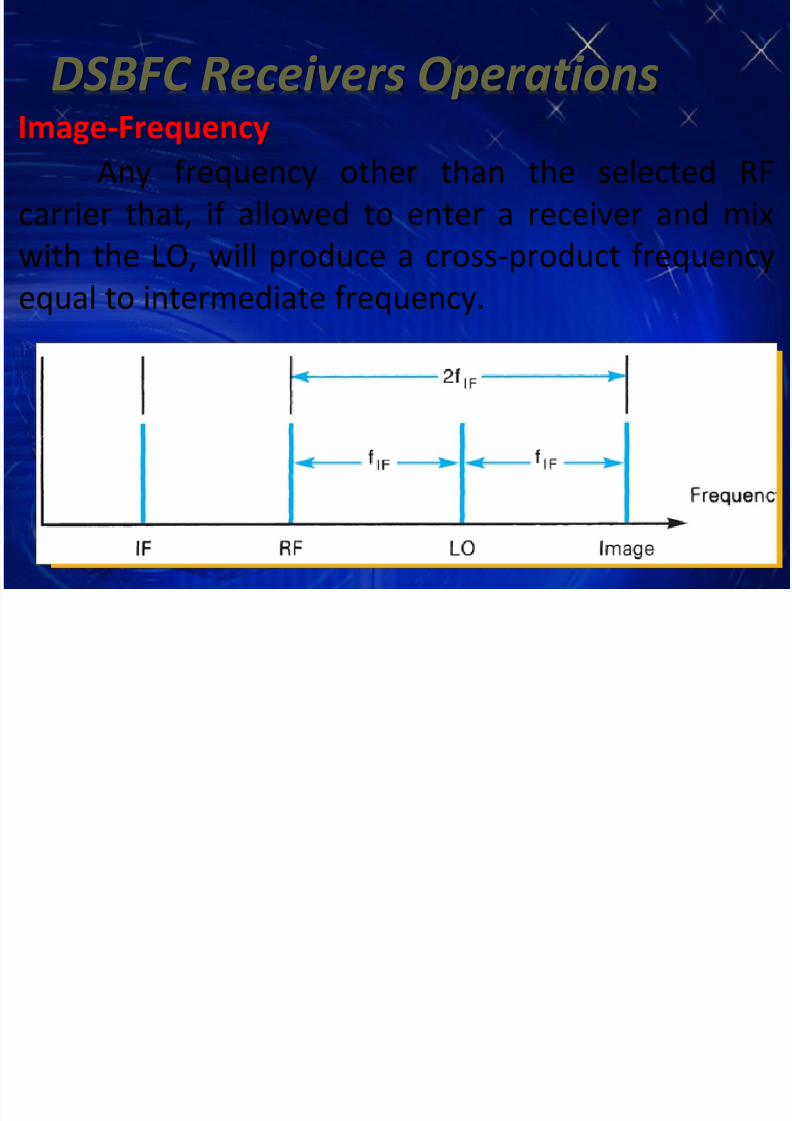
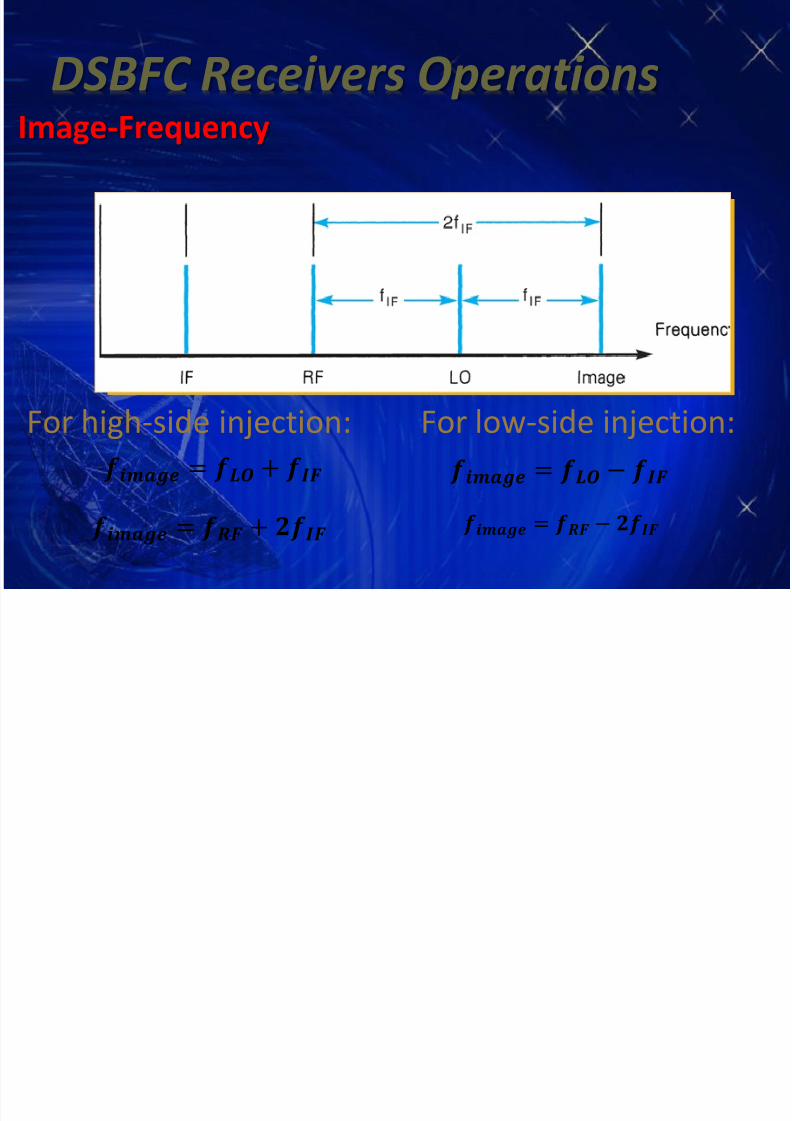
DSBFC Receivers OperationsImage-Frequency
Any frequency other than the selected RF
carrier that, if allowed to enter a receiver and mix
with the LO, will produce a cross-product frequency
equal to intermediate frequency.
7/21/2019 03_AM Transmission and Reception
http://slidepdf.com/reader/full/03am-transmission-and-reception 50/55
DSBFC Receivers OperationsImage-Frequency
For high-side injection: For low-side injection: = +
= +
=
=

7/21/2019 03_AM Transmission and Reception
http://slidepdf.com/reader/full/03am-transmission-and-reception 51/55
DSBFC Receivers Operations
Image-Frequency Rejection RatioMeasure of the ability of a preselector to reject
the image frequency.
221 Q IFRR
Where:
im
RF
RF
im
f
f
f
f
NOTE: If more than one tuned circuit is used the
total IFRR is the product of two ratios.

7/21/2019 03_AM Transmission and Reception
http://slidepdf.com/reader/full/03am-transmission-and-reception 52/55
DSBFC ReceiversSuperheterodyne Receiver

7/21/2019 03_AM Transmission and Reception
http://slidepdf.com/reader/full/03am-transmission-and-reception 53/55
DSBFC ReceiversSuperheterodyne Receiver
Detector Section:
Converts the IF signal back to
the original source information.called an audio detector or the
second detector
May be a single diode, phase-locked loop or balanced
modulator.

7/21/2019 03_AM Transmission and Reception
http://slidepdf.com/reader/full/03am-transmission-and-reception 54/55
DSBFC ReceiversSuperheterodyne Receiver

7/21/2019 03_AM Transmission and Reception
http://slidepdf.com/reader/full/03am-transmission-and-reception 55/55
DSBFC Receivers
Superheterodyne ReceiverAudio Amplifier Section:
Comprises several cascaded
audio amplifiers thatamplifies the demodulated
information to a level that
will drive one or morespeakers.


