92
| Date post: | 11-Dec-2016 |
| Category: |
Documents |
| Upload: | nguyenxuyen |
| View: | 213 times |
| Download: | 0 times |

��� � � � � � � � � � � � � � � � � � � � � �
������������ �� ��
������������������������ �! !�����"���#$!���%&��!$'� ���(!&'�#�����)�%!�*���*�$����
���������
JYVÄSKYLÄ STUDIES IN COMPUTING 91
Timo Nihtilä
UNIVERSITY OF
JYVÄSKYLÄ 2008
Esitetään Jyväskylän yliopiston informaatioteknologian tiedekunnan suostumuksellajulkisesti tarkastettavaksi yliopiston Villa Ranan Blomstedt-salissa
huhtikuun 18. päivänä 2008 kello 12.
Academic dissertation to be publicly discussed, by permission ofthe Faculty of Information Technology of the University of Jyväskylä,
in the Building Villa Rana, Blomstedt Hall, on April 18, 2008 at 12 o'clock noon.
JYVÄSKYLÄ
Reception Algorithms for High SpeedDownlink Packet Access
Performance of Advanced Transmission and

Performance of Advanced Transmission andReception Algorithms for High Speed
Downlink Packet Access

JYVÄSKYLÄ STUDIES IN COMPUTING 91
JYVÄSKYLÄ 2008
Performance of Advanced Transmission and
UNIVERSITY OF JYVÄSKYLÄ
Timo Nihtilä
Reception Algorithms for High SpeedDownlink Packet Access
Copyright © , by University of Jyväskylä
URN:ISBN:978-951-39-3249-7ISBN 978-951-39-3249-7 (PDF)
ISBN 978-951-39-3236-7 (nid.)ISSN 1456-5390
2008
Jyväskylä University Printing House, Jyväskylä 2008
EditorsTimo MännikköDepartment of Mathematical Information Technology, University of JyväskyläIrene Ylönen, Marja-Leena TynkkynenPublishing Unit, University Library of Jyväskylä

ABSTRACT
Nihtilä, TimoPerformance of Advanced Transmission and Reception Algorithms for High SpeedDownlink Packet AccessJyväskylä: University of Jyväskylä, 2008, 92 p.(+included articles)(Jyväskylä Studies in ComputingISSN 1456-5390; 91)ISBN 978-951-39-3236-7Finnish summaryDiss.
This work studies the system level performance of several advanced techniquesdeveloped for Wideband Code Division Multiple Access (WCDMA) which isthe most widely adopted technique for the air interface of 3rd generation (3G)wireless networks. The performance is evaluated particularly with High SpeedDownlink Packet Access (HSDPA) concept of WCDMA. The analysis considersthe performance of advanced signal reception algorithms in combination withantenna diversity techniques in various realistic HSDPA network scenarios. Theperformance of conventional Rake receiver is compared to a Linear MinimumMean Squared Error (LMMSE) chip level equalizer being capable of intra- andinter-cell interference suppression. The receiver performance is evaluated withand without receive diversity and different transmit antenna diversity techniques,namely Space-Time Transmit Diversity (STTD) from open loop concepts and sin-gle and dual stream Transmit Antenna Array (TxAA) from the closed loop trans-mit diversity techniques. Also the impact of different HSDPA packet schedulingstrategies, namely round robin and proportional fair scheduling, are observed.The performance evaluation is done by changing several network attributes suchas UE velocity, channel profiles and cell sizes. The study is done by means of ex-tensive system level simulations using a comprehensive dynamic WCDMA net-work simulation tool, which comprises detailed modeling of signal propagationmodels, user mobility, traffic models, physical layer, radio resource management(RRM) algorithms and part of the upper layers of a WCDMA radio access net-work.
Keywords: WCDMA, HSDPA, Rake, LMMSE, equalizer, receive diversity, trans-mit diversity, MIMO, TxAA, D-TxAA, STTD, system performance
Author Timo NihtiläDepartment of Mathematical Information TechnologyUniversity of JyväskyläFinland
Supervisor Professor Tapani RistaniemiDepartment of Mathematical Information TechnologyUniversity of JyväskyläFinland
Reviewers Professor Zhisheng NiuDepartment of Electronic EngineeringTsinghua UniversityChina
Dr., Docent Mikko ValkamaInstitute of Communications EngineeringTampere University of TechnologyFinland
Opponent Dr. Zekeriya UykanNokia Siemens NetworksFinland

ACKNOWLEDGEMENTS
This thesis is done while working as a researcher in the Department of Mathemat-ical Information Technology at the University of Jyväskylä from the beginning of2004 to the beginning of 2006 and after that as a senior research scientist in Mag-ister Solutions Ltd. The research was done in a co-operation project with Nokia.First of all, I want to thank all the parties involved in this project for allowing methe possibility to make this thesis and for the financial support during it.
Especially, I would like to thank my supervisor, Professor Tapani Ristaniemi,for taking me as a researcher to this project in the first place and for constant guid-ance during it and in the making of this thesis. I would like to thank my opponentDr. Zekeriya Uykan and the reviewers of this thesis, Professor Zhisheng Niu andDr., Docent Mikko Valkama. Special thanks to my colleague, Dr. Janne Kurjen-niemi, for fruiful co-operation, invaluable advice and help during this project.
Thanks to Marko Lampinen, Elena Virtej and Ville Haikola from Nokia forco-authoring the included articles and also for supporting my simulation workin other ways. Also thanks to other people from Nokia: Jorma Kaikkonen andSari Nielsen for supervising my research activities, Tero Henttonen and MikaKolehmainen for providing help with the simulator and Jianke Fan and MarkkuKuusela for support in some of the simulation campaigns. I would generallywant to thank all the current and past colleagues in University of Jyväskylä, Mag-ister Solutions Ltd and Nokia for being the most pleasant people to work with.
Thanks to Technological Foundation and Ulla Tuominen Foundation for fi-nancial support in the form of encouragement grants.
Big thanks to all my friends for their refreshing company, especially duringthe weekends. Clearing my mind regularly from work and research was veryimportant to my mental wellbeing during the years. And what’s a more efficientway of not thinking of soft handovers than suffering from hard hangovers...
Finally, I want to express my deepest gratitude to my parents Lasse andPirkko, my brother Antti and especially to my girlfriend Jutta. Thank you all forbeing there for me and believing in me. I dedicate this thesis to you.
Jyväskylä, March 2008
Timo Nihtilä

Ah, there’s nothing more exciting than science. You get all the fun ofsitting still, being quiet, writing down numbers, paying attention...Science has it all.
Seymour Skinner
ACRONYMS
16QAM 16 Quadrature Amplitude Modulation
64QAM 64 Quadrature Amplitude Modulation
2G 2nd Generation mobile communication system
3G 3rd Generation mobile communication system
3GPP 3rd Generation Partnership Project
ACK Acknowledgement
AMC Adaptive Modulation and Coding
AOA Angle of Arrival
AVI Actual Value Interface
BER Bit Error Rate
BTS Base Transceiver Station
CC Chase Combining
CDMA Code Division Multiple Access
C/I Carrier to Interference ratio
CIO Cell Individual Offset
CL Closed Loop
CL1 Closed Loop Mode 1
CLTD Closed Loop Transmit Diversity
CN Core Network
C-PICH Common Pilot Channel
CSI Channel State Information
CQI Channel Quality Indicator
DL Downlink
DCH Dedicated Channel
DiffServ Differentiated Services
DSCH Downlink Shared Channel
D-TxAA Dual stream Transmit Antenna Array
DTX Discontinuous tranmission
ECR Effective Coding Rate
EDGE Enhanced Data rates for GSM Evolution
FACH Forward Access Channel
FCS Fast Cell Selection

FDD Frequency Division Duplex
GHz Gigahertz, 109 cycles per second
GPRS General Packet Radio Service
GSM Global System for Mobile communication
HARQ Hybrid Automatic Repeat reQuest
HSDPA High Speed Downlink Packet Access
HS-DPCCH High Speed Dedicated Physical Control Channel
HS-DSCH High Speed Downlink Shared Channel
HS-PDSCH High Speed Physical Downlink Shared Channel
HS-SCCH High Speed Shared Control Channel
Hz Hertz, one cycle per second
I-LMMSE Interference aware Linear Minimum Mean Squared Error
IR Incremental Redundancy
ITU International Telecommunication Union
ITU-R ITU Radiocommunication sector
kB Kilobyte
kbps 103 bits per second
kHz Kilohertz, 103 cycles per second
LA Link Adaptation
LMMSE Linear Minimum Mean Squared Error
MAC Medium Access Control
MAC-hs Medium Access Control - High Speed
MAI Multiple Access Interference
Mbps 106 bits per second
Mcps 106 chips per second
MCS Modulation and Coding Scheme
MHz Megahertz, 106 cycles per second
MIMO Multiple Input Multiple Output
MMSE Minimum Mean Squared Error
MRC Maximum Ratio Combining
MUD Multi-user detection
NACK Negative Acknowledgement
PARC Per-Antenna Rate Control
P-CPICH Physical Common Pilot Channel

PDU Protocol Data Unit
PedA Pedestrian A
PF Proportional Fair
PIC Parallel Interference Cancellation
QoS Quality of Service
QPSK Quadrature Phase Shift Keying
RCQI Relative CQI
RLC Radio Link Control
RNC Radio Network Controller
RNS Radio Network Subsystem
RR Round Robin
RRM Radio Resource Management
RSCP Received Signal Code Power
RSVP Resource Reservation Protocol
Rx Receiver
SF Spreading Factor
SAW Stop-And-Wait
SMS Short Message Service
SNR Signal to Noise Ratio
SINR Signal to Interference and Noise Ratio
STTD Space-Time Transmit Diversity
TDD Time Division Duplex
TFRC Transport Format and Resource Combination
TTI Transmission Time Interval
Tx Transmitter
TxAA Transmit Antenna Array
UMTS Universal Mobile Communication System
UE User Entity
UL Uplink
UMTS Universal Mobile Telecommunication System
UTRAN UMTS Terrestrial Radio Access Network
VehA Vehicular A
WCDMA Wideband Code Division Multiple Access
WLAN Wireless Local Area Network
ZF Zero-Forcing
LIST OF FIGURES
FIGURE 1 UMTS architecture [3G04b, 3G06b]. . . . . . . . . . . . . . 30FIGURE 2 Adaptive modulation and coding. . . . . . . . . . . . . . . 33FIGURE 3 Modulation constellation diagrams and transmitted bits per
symbol (n). . . . . . . . . . . . . . . . . . . . . . . . . . 34FIGURE 4 Allocated transport block size in relation to CQI value. . . . . 36FIGURE 5 Retransmission functionality in HSDPA. . . . . . . . . . . . 38FIGURE 6 Proportional fair scheduling. . . . . . . . . . . . . . . . . 41FIGURE 7 HS-SCCH and HS-DSCH timing. . . . . . . . . . . . . . . 42FIGURE 8 Example of code allocation with code multiplexing. . . . . . 43FIGURE 9 Power allocation with static and dynamic HSDPA power allo-
cation (fixed HS-SCCH power). . . . . . . . . . . . . . . . 44FIGURE 10 HS-DSCH serving sector handover functionality. . . . . . . . 46FIGURE 11 Frequency selective and flat fading radio channels. . . . . . . 48FIGURE 12 Example of a multipath radio channel. . . . . . . . . . . . . 49FIGURE 13 Rake receiver block diagram [Hol04]. . . . . . . . . . . . . 52FIGURE 14 Multiple access interference. . . . . . . . . . . . . . . . . 53FIGURE 15 Block diagram of signal reception with channel equalization. . 54FIGURE 16 Studied transmit and receive antenna scenarios. . . . . . . . 58FIGURE 17 STTD transmit diversity operation block diagram [Ala98]. . . 60FIGURE 18 Single stream TxAA operation block diagram [3G04a]. . . . . 63FIGURE 19 Phase constellation in TxAA [Hot03]. . . . . . . . . . . . . 64FIGURE 20 The generic downlink transmitter structure to support MIMO
operation for HS-DSCH transmission. . . . . . . . . . . . . 67FIGURE 21 Achievable HS-DSCH throughput with single and dual stream
MCSs. Used modulation indicated. . . . . . . . . . . . . . 67FIGURE 22 Simulation scenario. . . . . . . . . . . . . . . . . . . . . 71FIGURE 23 Combined macro and indoor scenario. Building grid and macro
mobility area (dashed line) depicted at the center. . . . . . . 73FIGURE 24 Building layout and building mobility area (dashed line). Femto
BTS location depicted in the center. . . . . . . . . . . . . . 74

LIST OF TABLES
TABLE 1 Theoretical peak data rates of different telecommunica-tion systems. [Rys06] . . . . . . . . . . . . . . . . . . 20
TABLE 2 Terminal categories in HSDPA. . . . . . . . . . . . . . 35TABLE 3 An example MCS table for category 7 and 8 UEs. . . . . 37TABLE 4 Differences between DCH and HS-DSCH. . . . . . . . . 41TABLE 5 Channel profile power delay profiles. . . . . . . . . . . 48TABLE 6 BTS parameters. . . . . . . . . . . . . . . . . . . . . 74TABLE 7 Simulation parameters. . . . . . . . . . . . . . . . . . 75TABLE 8 Simulation parameters for the reliability analysis test case. 88TABLE 9 Statistical confidence intervals. . . . . . . . . . . . . . 89TABLE 10 Simulation results from 35 simulation runs with different
seeds. . . . . . . . . . . . . . . . . . . . . . . . . . 90TABLE 11 Cell throughput gain comparison between this thesis and
[Lov03]. . . . . . . . . . . . . . . . . . . . . . . . . 91TABLE 12 Cell throughput and gain comparison between this thesis
and [Ram03]. . . . . . . . . . . . . . . . . . . . . . . 91

CONTENTS
ABSTRACTACKNOWLEDGEMENTSACRONYMSLIST OF FIGURESLIST OF TABLESCONTENTSLIST OF INCLUDED ARTICLES
1 INTRODUCTION ............................................................................ 191.1 Research problem ..................................................................... 21
1.1.1 Advanced reception algorithms ...................................... 211.1.2 Receive diversity ........................................................... 221.1.3 Transmit diversity.......................................................... 221.1.4 Advanced packet scheduling .......................................... 221.1.5 Femto base station concept ............................................. 231.1.6 Summary ...................................................................... 23
1.2 Related studies and connection to thesis work............................. 241.3 Other articles ........................................................................... 271.4 Outline .................................................................................... 27
2 HIGH SPEED DOWNLINK PACKET ACCESS IN WCDMA ............... 292.1 UMTS architecture.................................................................... 292.2 Basics of WCDMA .................................................................... 29
2.2.1 Code Division Multiple Access technology ...................... 302.2.2 Power control ................................................................ 302.2.3 Soft handover................................................................ 312.2.4 Release ’99 WCDMA downlink ...................................... 31
2.3 High Speed Downlink Packet Access.......................................... 322.3.1 Link adaptation ............................................................. 322.3.2 Adaptive modulation and coding.................................... 332.3.3 Fast physical layer retransmissions.................................. 362.3.4 Fast scheduling at Node B .............................................. 392.3.5 Packet scheduler............................................................ 392.3.6 Channels in HSDPA ....................................................... 412.3.7 Radio resource management in RNC ............................... 432.3.8 Mobility management .................................................... 45
3 RECEIVER STRUCTURES ................................................................ 473.1 Multipath radio channels .......................................................... 47
3.1.1 Mathematical modeling of multipath radio channel .......... 493.2 Rake receiver ........................................................................... 51
3.2.1 Modeling of rake by linear filtering ................................. 523.3 Intra-cell interference ................................................................ 52
3.4 Inter-cell interference ................................................................ 533.5 Linear MMSE chip-level equalizer.............................................. 54
3.5.1 Modeling of equalizer by linear filtering .......................... 543.5.2 Interference aware equalizer ........................................... 55
4 ANTENNA DIVERSITY ................................................................... 574.1 Receive diversity ...................................................................... 584.2 Transmit diversity .................................................................... 59
4.2.1 Space time transmit diversity (STTD) .............................. 594.2.2 Closed loop transmit diversity ........................................ 624.2.3 Single stream Transmit Antenna Array (TxAA) ................ 634.2.4 Dual stream TxAA......................................................... 66
5 ACHIEVED RESULTS ...................................................................... 695.1 Research tool............................................................................ 695.2 Simulation scenario .................................................................. 70
5.2.1 Wrap-around macro scenario .......................................... 705.2.2 Combined macro-femto cell scenario ............................... 72
5.3 Simulation result analysis.......................................................... 745.3.1 Receive diversity and LMMSE chip-equalizer................... 755.3.2 Advanced scheduling .................................................... 765.3.3 STTD and single stream TxAA performance..................... 765.3.4 MIMO performance with HSDPA ................................... 775.3.5 Inter-cell interference cancellation ................................... 775.3.6 Femto cell performance .................................................. 78
6 CONCLUSIONS .............................................................................. 79
YHTEENVETO (FINNISH SUMMARY) .................................................... 81
REFERENCES ......................................................................................... 82
APPENDIX 1 STATISTICAL CONFIDENCE ANALYSIS OF THE SIMU-LATION RESULTS ........................................................... 88
APPENDIX 2 SIMULATION TOOL VERIFICATION ............................... 91
INCLUDED ARTICLES
LIST OF INCLUDED ARTICLES
PI T. Nihtilä, J. Kurjenniemi, M. Lampinen and T. Ristaniemi. WCDMA HS-DPA Network Performance with Receive Diversity and LMMSE ChipEqualization. Proceedings of the 16th International Symposium on Personal In-door and Mobile Radio Communications (PIMRC’05), Berlin, Germany, 2005.
PII J. Kurjenniemi, T. Nihtilä, M. Lampinen and T. Ristaniemi. Performanceof WCDMA HSDPA Network with Different Advanced Receiver Penetra-tions. Proceedings of the 8th International Symposium on Wireless Personal Mul-timedia Communications (WPMC’05), Aalborg, Denmark, 2005.
PIII T. Nihtilä, J. Kurjenniemi, E. Virtej and T. Ristaniemi. Performance of Trans-mit Diversity Schemes with Advanced UE Receivers in HSDPA Network.Proceedings of the 9th International Symposium on Wireless Personal MultimediaCommunications (WPMC’06), San Diego, CA, USA, 2006.
PIV J. Kurjenniemi, T. Nihtilä, E. Virtej and T. Ristaniemi. On the Effect ofReduced Interference Predictability to the HSDPA Network Performancewith Closed Loop Transmit Diversity. Proceedings of the 9th InternationalSymposium on Wireless Personal Multimedia Communications (WPMC’06), SanDiego, CA, USA, (Best paper award), 2006.
PV T. Nihtilä, J. Kurjenniemi, M. Lampinen and T. Ristaniemi. Performanceof receive diversity and LMMSE chip equalization in WCDMA HSDPAnetwork. Wireless Personal Communications, No. 43, Vol. 2, pp. 261-280, 2007.
PVI T. Nihtilä, J. Kurjenniemi and E. Virtej. System Level Analysis of Interfer-ence Aware LMMSE Chip Equalization in HSDPA Network. Proceedingsof the IEEE Symposium on Computers and Communications (ISCC’07), Aveiro,Portugal, 2007.
PVII T. Nihtilä, J. Kurjenniemi and M. Lampinen. Effect of Ideal Inter-cell Inter-ference Cancellation to HSDPA System Performance. Proceedings of the 18thIEEE International Symposium on Personal, Indoor and Mobile Radio Commu-nications (PIMRC’07), Athens, Greece, 2007.
PVIII T. Nihtilä. Capacity Improvement by Employing Femto Cells in a MacroCell HSDPA Network. Proceedings of the 13th IEEE Symposium on Computersand Communications (ISCC’08), Marrakech, Morocco, (accepted for publication),2008.
PIX T. Nihtilä. Increasing Femto Cell Throughput with HSDPA Using HigherOrder Modulation. 2nd International Networking and Communications Con-ference (INCC’08), Lahore, Pakistan, (accepted for publication), 2008.

PX T. Nihtilä and V. Haikola. HSDPA MIMO System Performance in MacroCell Network. Proceedings of the 2008 IEEE Sarnoff Symposium, Princeton,NJ, USA, (accepted for publication), 2008.
The author of this thesis was the main author of article PI for which heparticipated in simulation scenario construction, conducted simulations and par-ticipated in the modelling and implementation work. In article PII the authorparticipated in constructing the simulation scenarios, conducted the simulationsand participated in writing of the article. The author of this thesis was the mainauthor of article PIII and did part of the implementation and modelling workand conducted all the simulations. In addition to participating in the modellingand implementation work in article PIV the author contributed in simulation re-sult analysis and in writing of the article. The author of this thesis was the mainauthor in article PV, conducted most of the simulations and participated in themodelling and implementation of the studied schemes to the system simulator.The author was the main author in articles PVI and PVII, did all the modellingand conducted simulations and did the main part in result analysis. For articlesPVIII and PIX the author was the single author, did all the modelling and simu-lation work and conducted the result analysis. The author was the main authorin article PX, did all the modelling and conducted all the simulations and did themost part of the result analysis.
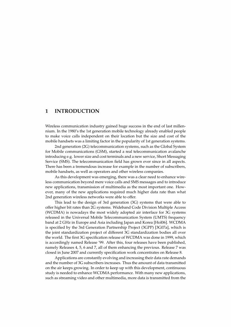
1 INTRODUCTION
Wireless communication industry gained huge success in the end of last millen-nium. In the 1980’s the 1st generation mobile technology already enabled peopleto make voice calls independent on their location but the size and cost of themobile handsets was a limiting factor in the popularity of 1st generation systems.
2nd generation (2G) telecommunication systems, such as the Global Systemfor Mobile communications (GSM), started a real telecommunication avalancheintroducing e.g. lower size and cost terminals and a new service, Short MessagingService (SMS). The telecommunication field has grown ever since in all aspects.There has been a tremendous increase for example in the number of subscribers,mobile handsets, as well as operators and other wireless companies.
As this development was emerging, there was a clear need to enhance wire-less communication beyond mere voice calls and SMS messages and to introducenew applications, transmission of multimedia as the most important one. How-ever, many of the new applications required much higher data rate than what2nd generation wireless networks were able to offer.
This lead to the design of 3rd generation (3G) systems that were able tooffer higher bit rates than 2G systems. Wideband Code Division Multiple Access(WCDMA) is nowadays the most widely adopted air interface for 3G systemsreleased in the Universal Mobile Telecommunication System (UMTS) frequencyband at 2 GHz in Europe and Asia including Japan and Korea [Hol06]. WCDMAis specified by the 3rd Generation Partnership Project (3GPP) [3G07a], which isthe joint standardization project of different 3G standardization bodies all overthe world. The first 3G specification release of WCDMA was done in 1999, whichis accordingly named Release ’99. After this, four releases have been published,namely Releases 4, 5, 6 and 7, all of them enhancing the previous. Release 7 wasclosed in June 2007 and currently specification work concentrates on Release 8.
Applications are constantly evolving and increasing their data rate demandsand the number of 3G subscribers increases. Thus the amount of data transmittedon the air keeps growing. In order to keep up with this development, continuousstudy is needed to enhance WCDMA performance. With many new applications,such as streaming video and other multimedia, more data is transmitted from the

20
base station to the mobile unit than vice versa. Due to this asymmetric data flow,particularly WCDMA downlink is expected to become the bottleneck of WCDMAsystem performance in the future.
Table 1 presents the comparison of peak data rates between different UMTSreleases and 2G technologies, such as GSM, General Packet Radio Service (GPRS),Enhanced Data rates for GSM Evolution (EDGE). The maximum theoretical datarate supported by UMTS Release ’99 is 2 Mbps for both uplink and downlinkbut it seems that the highest implemented data rate on the market is 384 kbpsso far [Hol06]. In UMTS specification Release 5 High Speed Downlink PacketAccess (HSDPA) was introduced to improve the capacity and spectral efficiencyof the WCDMA downlink [Hol06, Kol03, Par01]. The theoretical peak data ratefor Release 5 HSDPA is 14.4 Mbps. However, the actual user experienced peakdata rates are much lower than this.
TABLE 1 Theoretical peak data rates of different telecommunication systems. [Rys06]
System Peak data rateGSM 14.4 kbpsGPRS 171.2 kbpsEDGE 473.6 kbpsRel’99 WCDMA 2 MbpsRel 5 WCDMA (HSDPA) 14.4 MbpsRel 7 WCDMA (HSDPA+64QAM) 21.6 MbpsRel 7 WCDMA (HSDPA+MIMO) 28.8 Mbps
The latest 3GPP release included the support for higher order modulation64 phase Quadrature Amplitude Modulation (64QAM) and the use of a dualstream Multiple Input - Multiple Output (MIMO) scheme with HSDPA. 64QAMincreases the single stream peak data rates and using dual stream transmissionthe HSDPA theoretical peak data rate from Release 5 is doubled. So far 64QAMmodulation is not supported with MIMO transmission mode but the support forthat is expected to be in 3GPP Release 8.
Although Release 5 HSDPA already offers very good throughput to a mobileunit compared to 2G systems, there has been intense research to further improvethe data rate of HSDPA in future specification releases. This thesis studies thetechnologies that have been adopted in releases 6 and 7 and their performancein comparison to each others. In the next chapter, the research problem of thisthesis is addressed. Studies related to the problem are presented and discussedin chapter 1.2. In chapter 1.4 the outline of this thesis is presented.

21
1.1 Research problem
The studied technologies in this thesis can be divided into techniques that altereither the functionality of User Entity (UE) or the UMTS Terrestrial Radio AccessNetwork (UTRAN) or both of them. Techniques that can be adopted altering onlythe UE side are advanced receiver structures and receive (Rx) antenna diversity.The features that can be adopted solely at the UTRAN side are advanced HSDPApacket scheduling, open loop transmit (Tx) diversity and the femto base stationconcept. Techniques that affect both UE and UTRAN side are closed loop trans-mit diversity techniques which require alterations both to the base station in theform of multiple transmit antennas and to the receiver where feedback calcula-tion and the transmission of feedback information must be implemented.
1.1.1 Advanced reception algorithms
One of the main interference sources to a signal in WCDMA downlink are themultiple delayed replicas of the serving cell transmissions arriving at arbitrarytime shifts at the UE receiver which compromise the orthogonality of down-link spreading codes. The interference is mainly present at frequency-selectivechannels and is called Multiple Access Interference (MAI). Advanced receptionalgorithms, such as using channel equalization at chip-level, are one option tomitigate the effect of MAI. In this thesis the main focus in the advanced receiverfield is on one of the most prominent solutions the minimum mean squared error(MMSE) equalizer.
Although it is generally assumed that equalizer is used to cancel the inter-ference caused by serving cell transmissions, it is also possible to use equalizerin order to suppress inter-cell interference as well. This so called interferenceaware equalizer is assumed to be aware of the neighboring sector channel situa-tions and can estimate also their transmissions based on the temporal and moreimportantly the spatial characteristics of the interference using e.g. multiple an-tennas at the receiver. Thus, in this thesis it is studied what is the performancewhen also the inter-cell interference can be mitigated by equalization.
In this thesis a more general approach in advanced reception study is alsotaken by considering the effect of inter-cell interference mitigation in system per-formance point of view. Actual techniques are not considered but instead, themaximum achievable performance gains of different inter-cell interference miti-gation efficiencies are charted in a fully loaded HSDPA network. The means oreven the possibility to achieve the studied efficiencies are not considered. Thesystem performance is evaluated with different receivers with and without re-ceive diversity assuming some level of cancellation efficiency.

22
1.1.2 Receive diversity
Receive diversity is a powerful option when battling against signal fading at theUE side, especially at low power regions due to its power and diversity gain.The maximum performance can be achieved with uncorrelated receive antennasbut since some distance between the antennas is required to achieve reasonableuncorrelation between them, this might be challenging considering the size ofmobile units in general. Adopting multiple receive antennas increases both thecost and power consumption of the UE. These issues limit the applicability ofreceive diversity in reality. In this thesis the performance of receive diversity isevaluated with and without all the other studied techniques both at the UE andat the UTRAN side.
1.1.3 Transmit diversity
Transmit diversity has traditionally been considered a more feasible option thanreceive diversity. With open loop transmit diversity additional antennas andhardware modifications are adopted solely at the base station side. With closedloop techniques the added functionality at the receiver side is the feedback cal-culation, which is a relatively small modification. Thus the cost-effectivenessof transmit diversity schemes has been considered higher than receive diver-sity. However, although 3GPP specifications require transmit diversity supportmandatory for the UE, practical implementations of transmit diversity have notbeen widely adopted so far.
Transmit and receive diversity provide equally good diversity gain but thetechnical aspects in the employment of transmit diversity are more complicateddue to the loss of similar power gain as with receive diversity. This issue is morethoroughly addressed in chapter 4.2.
In this thesis the focus from the open loop transmit diversity techniques isin Space-Time Transmit Diversity (STTD) technique. Closed loop transmit di-versity study is divided into two branches focusing on single and dual streamtechniques. In both branches a technique called Transmit Antenna Array (TxAA)is considered. In single stream TxAA the transmitter uses two antennas to trans-mit a single transport stream as in dual stream TxAA (D-TxAA) two transportstreams are transmitted simultaneously. The transmit antenna weights are se-lected in a way that the inter-stream interference is minimized. In good channelconditions D-TxAA can enhance HSDPA bit rate significantly. D-TxAA was se-lected as the MIMO technique for HSDPA in Release 7.
1.1.4 Advanced packet scheduling
The impact of different packet scheduling strategies are also studied. Using asimple round robin scheduling algorithm the scheduling time is allocated equallybetween users. However, using this kind of blind scheduling the inherent poten-tial of the variating nature of the radio channel may be lost. Using an advanced

23
scheduling algorithm such as proportional fair in which users are scheduled in anopportunistic manner, the signal fading due to the radio channel can be turnedinto favour providing. Scheduling users at their best channel conditions intro-duces a new concept, multiuser diversity gain. Advanced packet scheduling of-fers the possibility to balance between user fairness and total system throughput.In this thesis the real potential of proportional fair is measured by comparing itto conventional round robin scheduling.
1.1.5 Femto base station concept
One potential solution to further increase the HSDPA bit rates is to introduce lowtransmission power base stations (BTS) in small isolated areas with insufficientor no macro cell coverage. These so called femto BTSs provide an access pointmainly to home or small office users who benefit from high signal to interfer-ence ratios due to the proximity of the base station unit. Another advantage isthat by using femto BTSs the network load is distributed to a higher number ofaccess points, thus decreasing the waiting times and increasing the network per-formance in high load situations. Due to high serving cell signal level comparedto neighboring cell signals in small cell sizes advanced receivers are expected togain from the femto cell solution. The performance of different receiver schemesin femto cells is one of the results of this thesis.
1.1.6 Summary
The main questions this thesis answers are:
• What is the expected gain of an advanced UE reception algorithm, namelyLMMSE chip level equalizer, over conventional rake reception on the sys-tem performance point of view?
• Do the observed gains vary when different realistic network situations areconsidered?
• How is the system performance affected when different penetration of ad-vanced receiver UEs are gradually added to the network?
• What is the gain of inter-cell interference suppressing LMMSE equalizerover conventional LMMSE equalizer?
• What are the maximum achievable gains of inter-cell interference cancella-tion with different receivers?
• How does employing receive and/or different transmit antenna diversitytechniques affect the observed gains with different receivers?
• Is there a difference in the achievable gains with advanced scheduling whendifferent UE receivers and/or antenna diversity are used?

24
• How does employing small cells in the network affect the realized gainswith different receivers?
To answer these questions, the performance of different receiver structures incombination with different antenna diversity schemes and scheduling strategiesin various realistic situations in a WCDMA HSDPA network is studied by meansof extensive dynamic system simulations, which are considered to reflect thereal network behavior well. The network performance is analyzed first of all interms of cell and user throughput. Cell throughput is the average instantaneousthroughput of a cell and user throughput is defined as the average throughputexperienced by a user during a call. Also signal quality and several other keyperformance indicators are used in the analysis.
1.2 Related studies and connection to thesis work
The performance of HSDPA network has been previously studied in e.g. [Kol02,Lov04, Ped04]. In [Kol02] the study considered different network setups anddifferent packet scheduling strategies thus covering the tradeoff between userfairness and cell throughput. It was found that HSDPA performance is affectedby multiple parameters, i.e. propagation environment, traffic characteristics andresource allocation policies.
In [Lov04] the system performance and physical layer aspects of HSDPAwere considered using simulations. A comparison of HSDPA and Release ’99system was done with different traffic models. The main conclusion was thatHSDPA offers 3 times better spectrum efficiency and cell and user throughputthan a Release ’99 system.
In [Tuo05] a spatial multiplexing approach to enhance the HSDPA systemperformance was introduced. Using receive and transmit diversity along withPer-Antenna Rate Control (PARC) a notable improvement in system performancecompared to single stream diversity methods was observed in both flat-fadingand frequency-selective fading channels. However, it was noticed that the im-provement was mainly seen by users having high signal-to-interference ratios.
The MMSE chip-level equalizer receiver solution studied in this thesis wasintroduced in [Kra00a] and its bit error rate (BER) performance was compared tozero-forcing (ZF) equalizer and Rake receivers. It was found that MMSE equal-izer BER performance is dramatically better than that of both ZF and Rake. Thesethree receiver structures were later studied further in [Kra00b] where the BERperformance comparison between antenna diversity and virtual channel diver-sity obtained through oversampling in a single received signal was presented.The obtained result was that spatial diversity is a more preferable solution thanoversampling diversity. Furthermore, MMSE once again out-performed ZF andRake receiver structures.
Linear intra-cell interference cancellation algorithms are previously stud-ied also in [Hoo02] where the chip-level equalization in the WCDMA downlink
25
before despreading was discussed. LMMSE and zero-forcing equalizer solutionwere studied in link level. The results were compared to the performance ofthe Rake receiver. The results showed significant performance improvementsof equalizer receivers over the conventional Rake receiver. On the other hand,parallel interference cancellation (PIC) algorithms that mitigate the intra-cell in-terference non-linearly was studied in [Div98].
There has also been a vast research in pursuit to suppress inter-cell inter-ference efficiently. However, the studies have rarely considered the system levelperformance. In [Sch02] the authors evaluated the system performance of a non-linear iterative successive cancellation algorithm among Rake and LMMSE re-ceivers. It was found that canceling inter-cell interference offers considerablesystem level gains both in indoor and vehicular channels.
A recent study of the WCDMA system performance for dedicated channelswhen a certain penetration of dual antenna terminals is assumed was presentedin [Ram02]. This analysis was extended in [Ven03] where in addition to dualantennas chip equalizers are also considered. Clear capacity gains over conven-tional Rake-based dual antenna reception were observed if the dual antenna ter-minal penetration was high enough. In that study no code resource limitationswere considered as in the simulations conducted in this thesis. In [Wan02] and[Lov03] the study was extended to the HSDPA network, where the Rake receiverand the LMMSE equalizer performance with and without receive diversity wasanalyzed. However, a quasi-static system level tool was used and hence no over-head on handovers was considered.
In [Oss04] transmit diversity techniques CL Mode 1, STTD and a systemwith two fixed beams were compared with system simulations. However, no re-ceive diversity or advanced receivers were considered. Also in [Ram03] the sys-tem performance of receive diversity and CL Mode 1 and STTD transmit diversityschemes were studied with different packet scheduling strategies in HSDPA butno advanced receivers were considered.
System level performance of open loop transmit diversity techniques incombination with single and dual receive antennas in HSDPA were studied in[Maj04] but no advanced receivers or closed loop transmit diversity were cov-ered. Performance analysis of the LMMSE equalizer in combination with multi-ple antenna schemes such as STTD and receive diversity was presented in [Pol04].However, unlike the results presented in this thesis, the simulations were quasi-static and closed loop Tx diversity performance was not considered.
Recently in [Oss05] and [Rin05], system level studies for HSDPA with andwithout closed loop transmit diversity were presented. Based on those resultsthe authors raised concerns that the reduced interference predictability results inan inherent problem for the CL Mode 1 to be used with HSDPA. Sudden inter-ference fluctuations (termed a "flashlight" effect by the authors) together with theassumptions used in the studies resulted in the scheduler to function improperly.The results of [Oss05] and [Rin05] indicated that the usage of closed loop transmitdiversity in HSDPA network is not advantageous at the cell boundaries.
On the other hand, another HSDPA study [Ber04] suggested that the HS-

26
DPA system is not impacted significantly by the increased interference variabilitydue to TxAA thanks to the efficient hybrid automatic repeat request (HARQ) op-eration and inherent radio channel quality report errors of the system. This studydid not include fully dynamic simulations, like the results presented in this the-sis, but were based on pre-calculated interference effects from detailed link levelstudies.
Academic research has indicated MIMO transmission potential for high datarates [Fos98, Tel99, Ges03, Gol03] and several MIMO candidates were proposedfor HSDPA in [3G07c]. The closed-loop MIMO schemes require knowledge of thechannel impact in the transmitter, and hence in theory the closed-loop schemeshave better performance than open-loop schemes. The D-TxAA benefits fromchannel knowledge, but still keeps the uplink feedback reasonable. Open-loopMIMO scheme was compared to receive diversity in [Lam05]. However, systemperformance evaluation of closed loop MIMO schemes for HSDPA have not beenwidely published. In [Hid06] D-TxAA was found to offer around 10 % gain inuser throughput over receive diversity in an urban microcell spatial channel.
In this thesis, the above mentioned studies are extended in various fields.The receivers equipped with LMMSE chip-level equalizers with and without dualantenna receive and/or transmit antennas are evaluated in a full HSDPA networkand present an analysis of the expected gains of different receiver - antenna di-versity combination schemes over conventional single antenna Rake receiver inrealistic situations by using a dynamic WCDMA system-level tool. From trans-mit diversity field an open loop concept called STTD is studied along with TxAAsingle stream closed loop transmit diversity technique. Also the performance ofa closed loop MIMO technique D-TxAA is studied in a macro cell environment.The macro cell environment is a challenging scenario for MIMO transmission,because high signal to interference and noise ratios are experienced only near thebase station. This leads to single stream usage of D-TxAA scheme in most casesand the gain of dual stream transmission is not achieved.
Both the code resource limitation and the most essential radio resource man-agement algorithms are modeled in detail. The impact of different packet schedul-ing strategies is considered. The study also covers different UE velocities to someextent and channel power delay profiles in order to evaluate the robustness ofadvanced receivers in different channel conditions.
Moreover, it is reasonable to assume that not all the receivers are advancedones immediately but the penetration of them in the network is an increasingfactor. Therefore the dynamic behavior of the system needs to be analyzed fromthe network and end-user perspective, i.e. how much gain is seen in the cellthroughput when advanced receiver penetration is increased and how the fair-ness of different users is maintained in terms of user throughput. The WCDMAHSDPA network performance is thus evaluated also from this point of view byassuming that the penetration of a certain advanced receiver type is graduallyincreased in the network.
In this thesis it is also studied whether the claimed "flashlight" effect ispresent in HSDPA network with closed loop transmit diversity. The study is done

27
by means of dynamic system level simulations. Moreover, in the performed sim-ulations the effect of intra-cell and inter-cell interference is explicitly modeled.This is in contrast to the modeling in [Rin05] where the interference was based onorthogonality matrix approximation.
1.3 Other articles
In addition to the included articles, the author of this thesis has also publishedseveral other articles considering 3G system quality of service (QoS) which arenot included in this thesis.
1. E. Wallenius, T. Hämäläinen, T. Nihtilä, J. Puttonen, J. Joutsensalo, Simula-tion Study on 3G and WLAN Interworking, IEICE Transactions on Commu-nications, Vol. E89-B, No. 2, pp. 446-459, 2006.
2. E. Wallenius, T. Hämäläinen, T. Nihtilä, K. Luostarinen, J. Joutsensalo, 3G/4Ginterworking with WLAN QoS 802.11e, Proceedings of the IEEE SemiannualVehicular Technology Conference, (VTC Fall 2003), October 2003, Orlando, USA.
3. T. Hämäläinen, E. Wallenius, T. Nihtilä, K. Luostarinen, End-to-End QoSIssues at the Integrated WLAN and 3G Environments, Proceedings of the9th Asia-Pacific Conference in Communications (APCC 2003), September 2003,Penang, Malaysia.
4. T. Hämäläinen, E. Wallenius, T. Nihtilä, K. Luostarinen, Providing QoS atthe Integrated WLAN and 3G Environments, Proceedings of the 14th IEEEInternational Symposium on Personal, Indoor and Mobile Radio Communications(PIMRC 2003), October 2003, Beijing, China.
5. E. Wallenius, T. Hämäläinen, T. Nihtilä, J. Joutsensalo, 3G and WLAN In-terworking QoS Solution, Proceedings of the 5th IEEE International Confer-ence on Mobile and Wireless Communications Networks (MWCN 2003), Septem-ber/October 2003, Singapore.
6. E. Wallenius, T. Hämäläinen, T. Nihtilä, J. Joutsensalo, Providing QoS in3G-WLAN Environment with RSVP and DiffServ, Proceedings of the 1st In-ternational Conference on E-business and Telecommunication Networks (ICETE2004), August 2004, Setúbal, Portugal.
1.4 Outline
In chapter 2 an introduction to UMTS and WCDMA technology is presented first.Then HSDPA concept and its features are discussed in more detail. In chapter 3different UE receiver structures are presented and the mathematical modeling

28
of them and the general WCDMA signal model are presented. In chapter 4 thebasics of receive and transmit antenna diversity are presented. Also differenttechniques used in WCDMA and their modeling is presented and discussed indetail. In chapter 5 the research tool is introduced and the achieved results arepresented. Finally, in chapter 6 conclusions are drawn.

2 HIGH SPEED DOWNLINK PACKET ACCESS INWCDMA
The HSDPA concept has been widely covered in [Hol06, Kol03, Par01] and thephysical layer aspects of it can be found in 3GPP specifications [3G01]. In thischapter a brief introduction to HSDPA is presented. First, the general structureand features of UMTS and its air interface WCDMA is covered in chapters 2.1and 2.2, respectively. In chapter 2.3 the enhancements of HSDPA technology toWCDMA downlink is presented.
2.1 UMTS architecture
The architecture of the UMTS system is depicted in Fig. 1. It consists of suchlogical network elements as core network (CN), user equipment (UE) and UMTSTerrestrial Radio Access Network (UTRAN) [3G04b]. The core network is re-sponsible for routing connections between external networks and UMTS. It isconnected to UTRAN via Iu interface. UTRAN handles all radio related func-tionality in UMTS.
UTRAN includes one or more Radio Network Subsystems (RNS), whichconsists of one Radio Network Controller (RNC) and at least one Node B (or basestation) [3G06b]. RNC owns and controls all Node Bs in its domain. RNCs areconnected to each other through the Iur interface and Node Bs to RNC via Iubinterace. UTRAN is ultimately connected to the UEs via the Uu interface, whichis the WCDMA air interface.
2.2 Basics of WCDMA
WCDMA physical layer has unique features that make it different from othermultiple access schemes. In this chapter the main characteristics of basic WCDMA

30
FIGURE 1 UMTS architecture [3G04b, 3G06b].
operation specified in Release ’99 and Release 4 is discussed more thoroughly.
2.2.1 Code Division Multiple Access technology
In WCDMA user data bits are spread over a wide bandwidth by multiplyingthem by pseudorandom spreading sequences consisting of very short durationbits called chips. Different users data is spread with different chip sequences(spreading codes) which have low cross-correlation values to each other. In thedownlink they are entirely orthogonal. As each user is operating on the samefrequency, their signals get mixed up at the receiver. Due to the low correlationof the spreading codes each user data can be recovered from the received signalby multiplying it with the same code used in spreading, hence the term CodeDivision Multiple Access. The length of the spreading code per data bit is calledthe spreading factor (SF). Channels maximum physical layer bit rate per codechannel is inversely proportional to the spreading factor.
The chip rate determines the operating bandwidth of the WCDMA system.3.84MHz chip-rate maps into approximately 5 MHz bandwidth. The wide band-width offers several benefits such as support for high data rates and increasedmultipath diversity.
2.2.2 Power control
Spreading codes are used to separate different users in the uplink and differentchannels in the downlink. As different transmissions use the same bandwidth,

31
the signals interfere with each other. To minimize the interference in WCDMAsystem the signal powers need to be controlled. The objective is to transmit withminimal power that is needed to receive the signal with acceptable quality. Aschannel variations cause the signal to fade very rapidly, the power control needsto be fast in order to maintain a constant received power level at the receiver. InWCDMA transmitter power is controlled by the inner loop power control at therate of 1500 Hz.
The inner loop power control is based on a closed loop algorithm. The re-ceiver measures the signal to noise ratio (SNR) of the received signal and com-pares that to the target. If the signal is below the target, the receiver tells thetransmitter to increase its power and vice versa. Outer loop power control is thenresponsible for measuring the signal quality and altering the signal level target towhich the received signal is compared. Outer loop power control is adjusted in10 ms intervals (after each received radio frame). If a frame is received correctly,the SNR target is decreased. If an error occurs, target is increased.
2.2.3 Soft handover
As all Node Bs in WCDMA system are transmitting with the same frequency, thisallows a user to be connected to more than one Node B at a time. This connectiontype is generally called soft handover. If a user measures that the power levels ofmore than one sector belonging to the same or a different Node B are adequatelygood, the user can establish a soft handover connection to them. The connectionto two or more sectors of the same Node B is called softer handover. If the con-nection is between multiple sectors belonging to different Node Bs, it is called asoft handover.
Soft/softer handover decreases both the uplink and downlink interferencelevels. In the uplink the signal sent by the UE is received by multiple sectors.Their received signals can be combined and thus the UE does not need to transmitwith as high power as if it would be connected only to a single sector. The sameeffect takes place in the downlink. The sectors can transmit with lower power asthe UE can combine the received signals.
On the other hand, the code resources for one user need to be reserved frommultiple sectors and thus excessive soft handover connections can limit the ca-pacity.
2.2.4 Release ’99 WCDMA downlink
Downlink packet data transmission is already supported in Release ’99. Thechannel possibilities to use a packet data service in the specifications are
• Dedicated Channel (DCH),
• Downlink Shared Channel (DSCH) and
• Forward Access Channel (FACH).
32
DCH has a fixed spreading factor in the downlink i.e. it reserves the code ca-pacity according to the maximum bit rate of the connection. This is not the mostefficient use of code resources since a lot of applications’ bit rate demands varysignificantly during the connection. With these applications a big portion of coderesources would be wasted during low activity periods.
DSCH always operates alongside DCH and it is meant mainly for packetdata. It’s has a dynamically varying SF in 10 ms periods. Its code resources canbe divided between users and it supports single code or multicode transmission.DSCH can be fast power controlled with the associated DCH but it does not sup-port soft handover.
FACH is operated normally on its own with a fixed spreading factor anda rather high power to reach all users in the cell. FACH does not support fastpower control or soft handover [Hol06].
2.3 High Speed Downlink Packet Access
This chapter presents the basic architecture and features of WCDMA HSDPA con-cept [Hol06, 3G06c]. HSDPA was introduced in 3GPP Release 5. The purpose wasto increase Release ’99 and Release 4 downlink packet data transmission perfor-mance. Three new channels were introduced with HSDPA [3G05]. All the userdata is carried on the high speed downlink shared channel (HS-DSCH). Its as-sociated control channel is the high speed shared control channel (HS-SCCH).Uplink control channel is the high speed dedicated physical control channel (HS-DPCCH). The channels are more thoroughly addressed in chapter 2.3.6.
As Release ’99 packet data transmission using DCH, DSCH and FACH chan-nels can be considered as quite static and slow in nature, HSDPA offers a fastand dynamic transmission scheme efficiently utilizing the potential inherent inWCDMA technology. This is achieved through several advanced techniques pre-sented in the following chapters.
2.3.1 Link adaptation
Basic WCDMA functionality in Release ’99 follows the changes in link qualitywith fast power control and targets to keep the received downlink SNR equalbetween different users. In HSDPA the spreading factor and the link power (ifstatic power allocation is used) of the user data channel are kept constant butthe quality of the link is tracked by the UE and reported to the Node B by the linkadaptation (LA) function in order to exploit and to adapt to the dynamic variationsin link quality.
Each UE sends a periodic channel quality indicator (CQI) message at eachtransmission time interval (TTI) to the Node B. The CQI indicates the maximumtransport block the UE can receive with not more than 10 % error probability atthe current channel situation. UE measures the Common Pilot Channel (C-PICH)
33
signal strength and sends an integer between 0 and 30 which corresponds to thepilot carrier to interference ratio (C/I). Node B first compensates the CQI withthe power offset between the C-PICH and HS-DSCH. In Node B there is also alink adaptation outer loop operational, which corrects the received CQI with aspecific correction factor [Ped04, Nak02]. The correction factor is altered basedon the success of past transmissions. If the error probability of sent transportblocks is higher than the target, reported CQI is lowered to ensure a more reliabletransmission and vice versa.
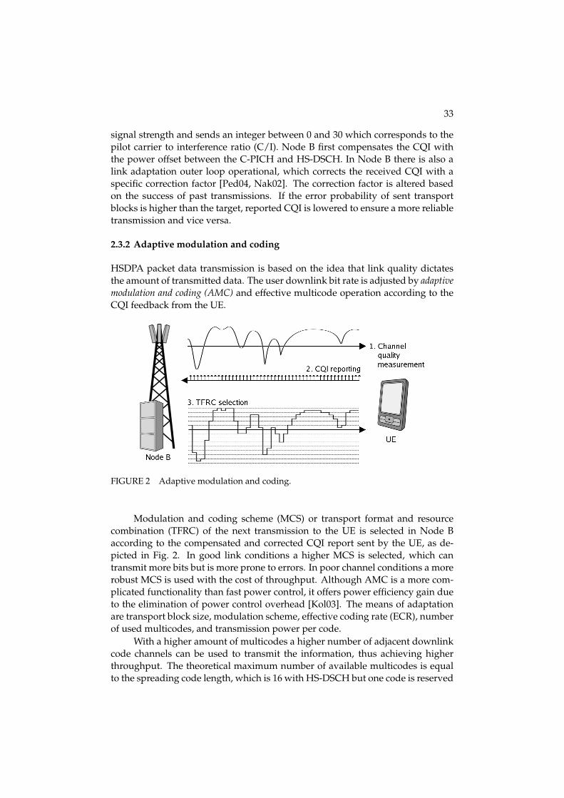
2.3.2 Adaptive modulation and coding
HSDPA packet data transmission is based on the idea that link quality dictatesthe amount of transmitted data. The user downlink bit rate is adjusted by adaptivemodulation and coding (AMC) and effective multicode operation according to theCQI feedback from the UE.
FIGURE 2 Adaptive modulation and coding.
Modulation and coding scheme (MCS) or transport format and resourcecombination (TFRC) of the next transmission to the UE is selected in Node Baccording to the compensated and corrected CQI report sent by the UE, as de-picted in Fig. 2. In good link conditions a higher MCS is selected, which cantransmit more bits but is more prone to errors. In poor channel conditions a morerobust MCS is used with the cost of throughput. Although AMC is a more com-plicated functionality than fast power control, it offers power efficiency gain dueto the elimination of power control overhead [Kol03]. The means of adaptationare transport block size, modulation scheme, effective coding rate (ECR), numberof used multicodes, and transmission power per code.
With a higher amount of multicodes a higher number of adjacent downlinkcode channels can be used to transmit the information, thus achieving higherthroughput. The theoretical maximum number of available multicodes is equalto the spreading code length, which is 16 with HS-DSCH but one code is reserved

34
for common channels and the associated DCH. Thus, up to 15 multicodes can beallocated for HSDPA user data transmission.
Two different modulation techniques are used in Release 5 HSDPA: quadra-ture phase shift keying (QPSK) which is used also with DCH and a higher or-der 16 phase quadrature amplitude modulation (16QAM). QPSK is more robustenduring lower channel quality whereas 16QAM offers higher throughput butrequires a higher signal to interference and noise ratio (SINR) for good perfor-mance.
However, in indoor situations the SINR can be so high that even with 16QAM,highest ECR (lowest coding protection) and with highest amount of used multi-codes the bit error probability is still lower than the target. This means that morebits could be delivered with acceptable quality. Therefore, the superior signalquality is not fully exploited and resources are wasted. In exceptionally good linkconditions 64QAM is an option to achieve larger transport block sizes than with16QAM or QPSK. 3GPP Release 7 included the possibility to use 64QAM withHS-DSCH [3G07b]. The constellation diagrams of QPSK, 16QAM and 64QAMare presented in Figure 3. 64QAM delivers most bits per symbol but the small-est distance between adjacent symbols makes 64QAM also most susceptible tosymbol errors of the presented modulation schemes.
FIGURE 3 Modulation constellation diagrams and transmitted bits per symbol (n).
Another link adaptation technique is to change the coding rate of the trans-mission according to the link quality. This means that the transmitted bit streamis added with coding bits so that despite possible bit errors due to poor chan-nel quality the original payload bits can still be retrieved from the received bitstream. Higher coding protection results in a more error robust transmission butnaturally fewer number of payload bits can be delivered, which decreases theachievable throughput.
If in exceptionally good channel conditions the error probability target isnot reached by using other adaptation techniques (modulation, number of multi-codes, ECR) it is also possible to use lower the transmission power per code. Thisdoes not increase the achieved bit rate but it decreases the interference caused toother users.
The link adaptation dynamics for each UE depends on the UE capability to
35
support the different adaptation techniques. Especially in the early phase of HS-DPA deployment, all devices will not necessarily support, for example 16QAMmodulation or more than five parallel codes.
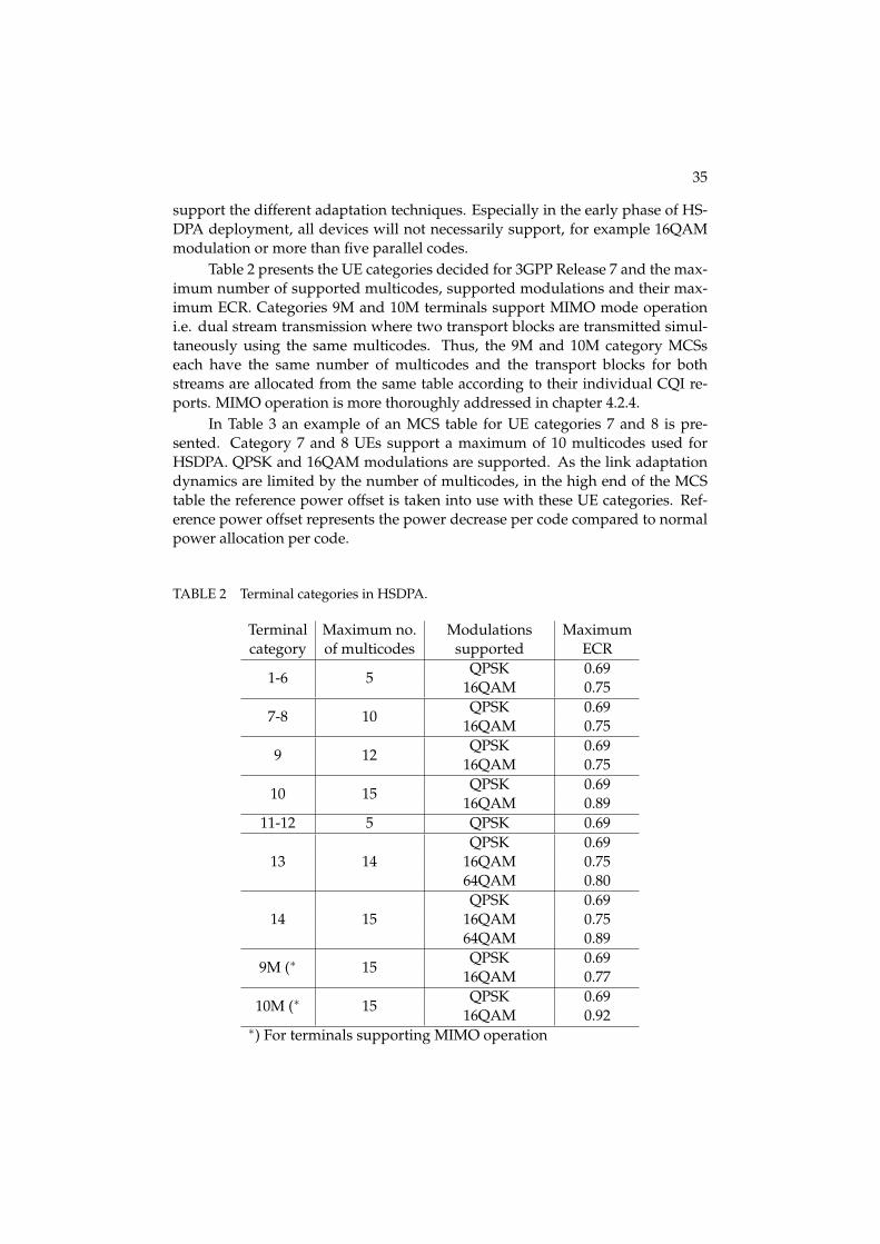
Table 2 presents the UE categories decided for 3GPP Release 7 and the max-imum number of supported multicodes, supported modulations and their max-imum ECR. Categories 9M and 10M terminals support MIMO mode operationi.e. dual stream transmission where two transport blocks are transmitted simul-taneously using the same multicodes. Thus, the 9M and 10M category MCSseach have the same number of multicodes and the transport blocks for bothstreams are allocated from the same table according to their individual CQI re-ports. MIMO operation is more thoroughly addressed in chapter 4.2.4.
In Table 3 an example of an MCS table for UE categories 7 and 8 is pre-sented. Category 7 and 8 UEs support a maximum of 10 multicodes used forHSDPA. QPSK and 16QAM modulations are supported. As the link adaptationdynamics are limited by the number of multicodes, in the high end of the MCStable the reference power offset is taken into use with these UE categories. Ref-erence power offset represents the power decrease per code compared to normalpower allocation per code.
TABLE 2 Terminal categories in HSDPA.
Terminal Maximum no. Modulations Maximumcategory of multicodes supported ECR
1-6 5QPSK 0.69
16QAM 0.75
7-8 10QPSK 0.69
16QAM 0.75
9 12QPSK 0.69
16QAM 0.75
10 15QPSK 0.69
16QAM 0.8911-12 5 QPSK 0.69
13 14QPSK 0.69
16QAM 0.7564QAM 0.80
14 15QPSK 0.69
16QAM 0.7564QAM 0.89
9M (∗ 15QPSK 0.69
16QAM 0.77
10M (∗ 15QPSK 0.69
16QAM 0.92∗) For terminals supporting MIMO operation
36
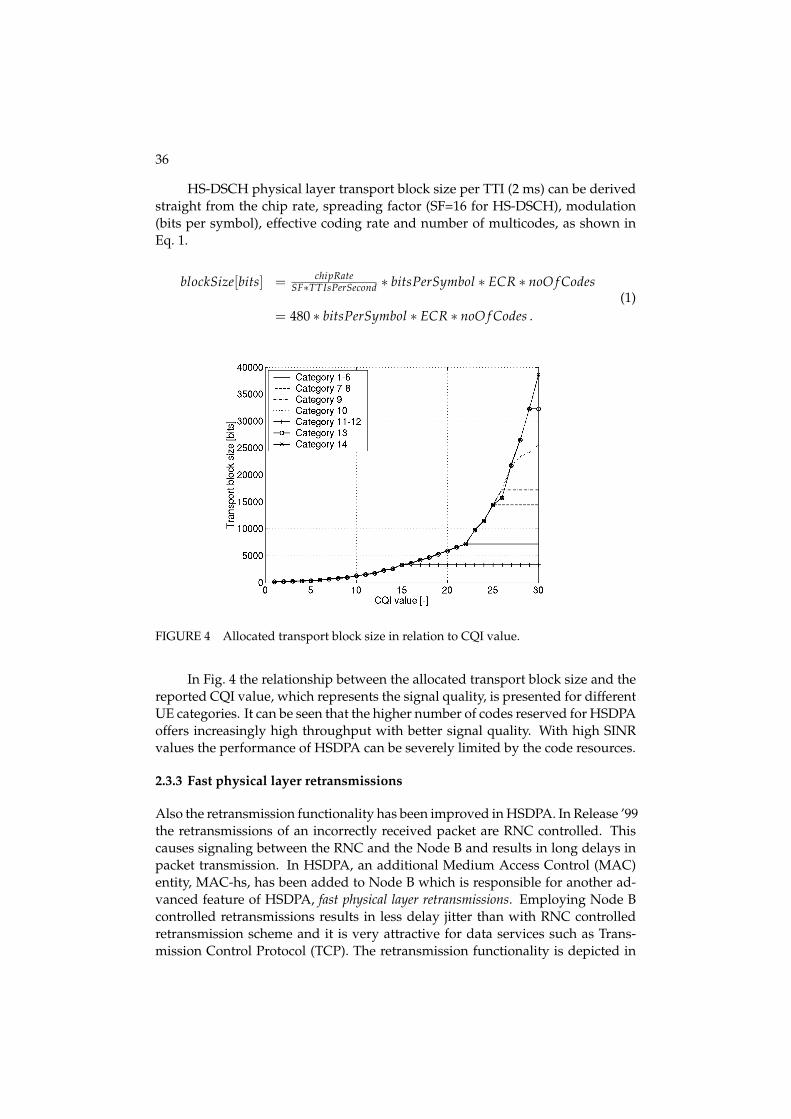
HS-DSCH physical layer transport block size per TTI (2 ms) can be derivedstraight from the chip rate, spreading factor (SF=16 for HS-DSCH), modulation(bits per symbol), effective coding rate and number of multicodes, as shown inEq. 1.
blockSize[bits] = chipRateSF∗TTIsPerSecond ∗ bitsPerSymbol ∗ ECR ∗ noO f Codes
= 480 ∗ bitsPerSymbol ∗ ECR ∗ noO f Codes .(1)
FIGURE 4 Allocated transport block size in relation to CQI value.
In Fig. 4 the relationship between the allocated transport block size and thereported CQI value, which represents the signal quality, is presented for differentUE categories. It can be seen that the higher number of codes reserved for HSDPAoffers increasingly high throughput with better signal quality. With high SINRvalues the performance of HSDPA can be severely limited by the code resources.
2.3.3 Fast physical layer retransmissions
Also the retransmission functionality has been improved in HSDPA. In Release ’99the retransmissions of an incorrectly received packet are RNC controlled. Thiscauses signaling between the RNC and the Node B and results in long delays inpacket transmission. In HSDPA, an additional Medium Access Control (MAC)entity, MAC-hs, has been added to Node B which is responsible for another ad-vanced feature of HSDPA, fast physical layer retransmissions. Employing Node Bcontrolled retransmissions results in less delay jitter than with RNC controlledretransmission scheme and it is very attractive for data services such as Trans-mission Control Protocol (TCP). The retransmission functionality is depicted in

37
TABLE 3 An example MCS table for category 7 and 8 UEs.
CQI valueTransport No. of Coding
ModulationReference
block size multicodes rate power[bits] offset [dB]
1 137 1 0.14 QPSK 02 173 1 0.18 QPSK 03 233 1 0.24 QPSK 04 317 1 0.33 QPSK 05 377 1 0.39 QPSK 06 461 1 0.48 QPSK 07 650 2 0.34 QPSK 08 792 2 0.41 QPSK 09 931 2 0.48 QPSK 0
10 1262 3 0.44 QPSK 011 1483 3 0.51 QPSK 012 1742 3 0.60 QPSK 013 2279 4 0.59 QPSK 014 2583 4 0.67 QPSK 015 3319 5 0.69 QPSK 016 3565 5 0.37 16QAM 017 4189 5 0.44 16QAM 018 4664 5 0.49 16QAM 019 5287 5 0.55 16QAM 020 5887 5 0.61 16QAM 021 6554 5 0.68 16QAM 022 7168 5 0.75 16QAM 023 9719 7 0.72 16QAM 024 11418 8 0.74 16QAM 025 14411 10 0.75 16QAM 026 14411 10 0.75 16QAM -127 14411 10 0.75 16QAM -228 14411 10 0.75 16QAM -329 14411 10 0.75 16QAM -430 14411 10 0.75 16QAM -5

38
Fig. 5. In the figure there is illustrated an example of the transmission strategy ofa Radio Link Control (RLC) Protocol Data Unit (PDU). The PDU is sent by RNCto Node B to the UE specific PDU buffer. Node B constructs a HSDPA transportblock from RLC PDUs in the buffer and sends it to the UE.
When the transport block is successfully received, the UE sends an acknowl-edgement (ACK) of the transport block to the Node B, which forwards the RLCACKs to RNC. If the transport block is not successfully received after the maxi-mum number of retransmissions, an RLC negative acknowledgement (NACK) issent, which triggers the RLC retransmission of lost packet(s), if the RLC acknowl-edgement mode is used. However, RLC retransmissions are usually needed onlyin HSDPA sector handovers, which are hard handovers and some packet lossmight occur. Since the physical layer retransmissions are handled in Node B,the ACK/NACK signaling can be executed between UE and Node B with veryminimal delay.
FIGURE 5 Retransmission functionality in HSDPA.
Due to the long delays in Release ’99 retransmission functionality the in-formation of previous transmissions cannot be utilized at all when detecting re-transmissions, making all transmission attempts totally independent. Due to thesmall retransmission delay of HSDPA the utilization of the previous transmis-sions is enabled. Using the hybrid automatic repeat request (HARQ) functionalitythe energy of different transmission attempts of a transport block can be com-bined and thus be able to increase the probability to receive the transmissioncorrectly. Buffering the previous transmissions however requires memory fromthe UE. The retransmission can be either identical to the first transmission whichis called chase combining (CC) [Cha85] or contain different bits compared withchannel encoder output that was received during the last transmission that is re-ferred as incremental redundancy (IR). With IR one can achieve a diversity gainas well as improved decoding efficiency. Performance and modeling of CC andIR for system simulations are presented in [Fre02].
39
2.3.4 Fast scheduling at Node B
HSDPA scheduling is quite different from the DCH scheduling. DCH reservescode resources for the whole TTI according to the peak data rate of the connectionduring the TTI. If the TTI period is long, the application may lower its data ratedemands during that and code resources are wasted.
To increase the efficiency of the resource allocation HSDPA transmission isdivided into short TTIs of 3 time slots (2 ms). The use of short TTI length enablesthe dynamic resource sharing between users by the fast scheduling at Node B. WithHSDPA all usable data transmission resources are used for a single user at eachTTI separately. If a user has no data to transmit in a TTI, the resources of that TTIare allocated to some other user with data to transmit.
2.3.5 Packet scheduler
The basic purpose of the packet scheduler is to share the HS-DSCH resourcesbetween users eligible for receiving data. The scheduling decision of a user isdone in HSDPA by the packet scheduler and can be based on several issues:
• quality feedback from the UE,
• UE data reception capability,
• resource availability,
• data buffer status and
• quality of service (QoS) and priority of data.
The scheduling algorithm can be based on all or some of the listed items. How-ever, the two main parameters of the scheduler is the importance of
1. maintaining efficient HS-DSCH utilization and
2. sharing resources fairly between users.
Either point would be easy to fulfill if the other part would not have to be takeninto account. Discarding the first clause, always scheduling the user with the bestsignal quality maximizes the network throughput. Maximum carrier to interfer-ence ratio (Max C/I) or maximum throughput scheduler is an implementation ofthis. It allocates HS-DSCH resources solely to users with a high channel quality.With this scheduler the worst signal quality users may never be scheduled.
On the other hand, highest order fairness is realized when every user isscheduled equally no matter what their signal quality is at the moment of schedul-ing. Round robin is this kind of scheduler in HSDPA.
In order to offer the best possible quality of service to all users while main-taining efficient HS-DSCH utilization is a challenging task. One solution to thistask is to exploit the nature of multipath fading channels. When fading occurs
40
the signal power variates from very low to very high. As users’ signals fade inde-pendently it is always beneficial to allocate channel resources to the user whosechannel is at its peak. With this kind of scheduler the HSDPA system is able tobenefit from the short term variations of the channel and to utilize the multiuserdiversity gain inherent in fading channels.
Proportional fair scheduler
One scheduling algorithm which takes into account both the expected through-put and the fairness of resource sharing is the proportional fair (PF) scheduler[Hol00]. PF calculates a relative CQI (RCQI) for each user using the expectedthroughput (signal quality) and the amount of previously transmitted data (fair-ness) as parameters. The user which has the highest relative CQI is scheduled.The relative CQI for user k at scheduling interval (TTI) n can be defined as
RCQIk[n] =Rk[n]Tk[n]
=min
{CQIk[n], Bk
tTTI
}Tk[n]
, (2)
where Rk[n] is the user k’s supported throughput in the next TTI, Tk[n] is the av-erage delivered user throughput in the past, Bk[n] is the amount of data pendingfor user k at the current TTI, and tTTI is the TTI length, 2 ms. The amount of datain the buffer for the user is taken into account in order to reduce the possibilityof wasted channel capacity due to the scheduling of a user with a low amountof data in good channel conditions. The "min" function is disabled after 1 sec-ond to avoid excess delays when buffer occupancy is low. The average deliveredthroughput is calculated recursively as
Tk[n] =(
1 − {Bk[n] > 0} · 1Nk
)Tk[n − 1] +
1Nk
R′k[n − 1] , (3)
where Nk is the forgetting factor, R′k is the actual throughput transmitted to the
UE at the nth TTI. The {Bk[n] > 0} term is either 1 or 0 depending on whetherthere is data in the Node B buffer for user k or not.
The forgetting factor is an important parameter in proportional fair schedul-ing. It defines how much weight is given for signal quality and how much for thefairness. With the forgetting factor, it can be decided whether PF scheduling be-havior resembles more Max C/I or round robin scheduling.
The basic idea of the scheduling algorithm is presented in Fig. 6. In the fig-ure UE 1 is scheduled first. As the expected throughput (signal strength) of UE2 increases, it gets the scheduling turn at time t1 although UE 1 has a higher ex-pected throughput. This is due to UE 2 having low average delivered throughputwhich increases its priority metric over UE 1, which has high average deliveredthroughput. As UE 2 signal strength decreases UE 3 gets the scheduling turn attime t2 for the same reason over UEs 1 and 2. All the time UE 1 is not scheduled,its average delivered throughput decreases. After UE 3 signal worsens, UE 1 getsthe scheduling turn back at time t3 due to its good signal quality in addition tolow average delivered throughput in the past.

41
FIGURE 6 Proportional fair scheduling.
2.3.6 Channels in HSDPA
In this chapter the HSDPA user data channel HS-DSCH, its associated signalingchannel HS-SCCH and the uplink control channel HS-DPCCH are discussed.
High speed downlink shared channel
HS-DSCH is the user data channel in HSDPA. It is mapped to the high speedphysical downlink shared channel (HS-PDSCH) in the physical layer. The differ-ences between main user data channel in Release ’99, DCH and HS-DSCH havebeen listed in Table 4.
TABLE 4 Differences between DCH and HS-DSCH.
Feature DCH HS-DSCHSpreading factor Variable, 4-512 Fixed, 16Fast power control Yes NoSoft handover support Yes NoMulti-code operation Yes Yes, extendedAdaptive modulation and coding No YesPhysical layer retransmissions No YesNode B based scheduling No YesLink adaptation No YesTTI length 10, 20, 40 or 80 ms 2 ms
Modulation QPSKQPSK/16QAM/64QAM
42
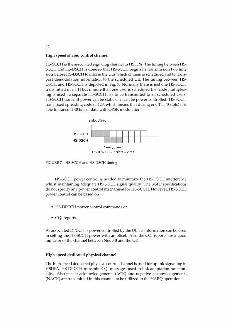
High speed shared control channel
HS-SCCH is the associated signaling channel in HSDPA. The timing between HS-SCCH and HS-DSCH is done so that HS-SCCH begins its transmission two timeslots before HS-DSCH to inform the UEs which of them is scheduled and to trans-port demodulation information to the scheduled UE. The timing between HS-DSCH and HS-SCCH is depicted in Fig. 7. Normally there is just one HS-SCCHtransmitted in a TTI but if more than one user is scheduled (i.e. code multiplex-ing is used), a separate HS-SCCH has to be transmitted to all scheduled users.HS-SCCH transmit power can be static or it can be power controlled. HS-SCCHhas a fixed spreading code of 128, which means that during one TTI (3 slots) it isable to transmit 40 bits of data with QPSK modulation.
FIGURE 7 HS-SCCH and HS-DSCH timing.
HS-SCCH power control is needed to minimize the HS-DSCH interferencewhilst maintaining adequate HS-SCCH signal quality. The 3GPP specificationsdo not specify any power control mechanism for HS-SCCH. However, HS-SCCHpower control can be based on
• HS-DPCCH power control commands or
• CQI reports.
As associated DPCCH is power controlled by the UE, its information can be usedin setting the HS-SCCH power with an offset. Also the CQI reports are a goodindicator of the channel between Node B and the UE.
High speed dedicated physical channel
The high speed dedicated physical control channel is used for uplink signalling inHSDPA. HS-DPCCH transmits CQI messages used in link adaptation function-ality. Also packet acknowledgements (ACK) and negative acknowledgements(NACK) are transmitted in this channel to be utilized in the HARQ operation.
43
2.3.7 Radio resource management in RNC
Radio resource management (RRM) algorithms are needed to utilize the physicallayer improvements of HSDPA to ultimately benefit end users. RRM functional-ity is divided between the RNC and Node B. At RNC, new HSDPA related RRMalgorithms are resource allocation, admission control and mobility management.
Resource allocation
Resource allocation is responsible for allocating power and channelization codesto Node B for HSDPA in each cell. It is generally more advantageous to allocateas many channelization codes for high speed physical downlink shared channel(HS-PDSCH) as possible since the spectral efficiency of HS-DSCH is thereforeimproved. Allocating more codes for HSDPA usage leaves less codes for otherchannels. This might eventually result in call blocking of Release ’99 users. How-ever, RNC may release HS-PDSCH codes rapidly in case of code congestion.
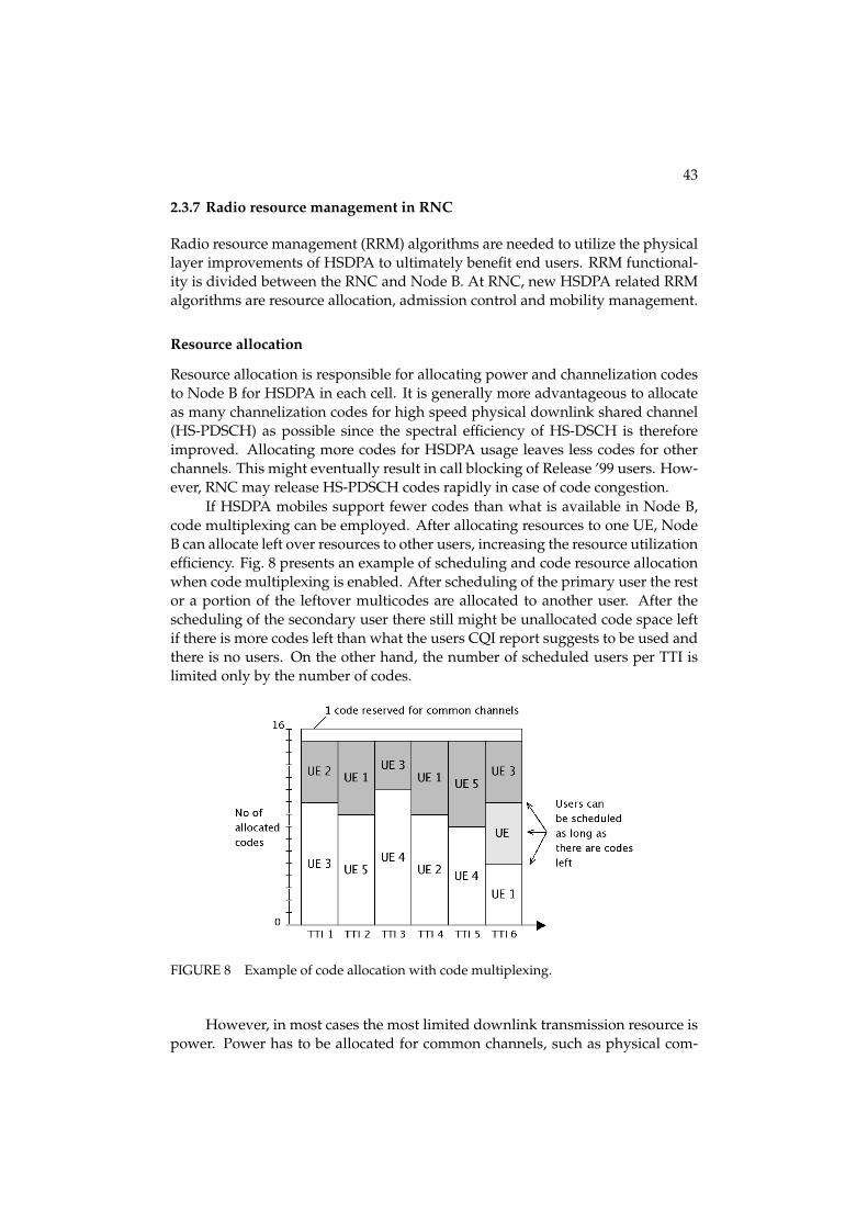
If HSDPA mobiles support fewer codes than what is available in Node B,code multiplexing can be employed. After allocating resources to one UE, NodeB can allocate left over resources to other users, increasing the resource utilizationefficiency. Fig. 8 presents an example of scheduling and code resource allocationwhen code multiplexing is enabled. After scheduling of the primary user the restor a portion of the leftover multicodes are allocated to another user. After thescheduling of the secondary user there still might be unallocated code space leftif there is more codes left than what the users CQI report suggests to be used andthere is no users. On the other hand, the number of scheduled users per TTI islimited only by the number of codes.
FIGURE 8 Example of code allocation with code multiplexing.
However, in most cases the most limited downlink transmission resource ispower. Power has to be allocated for common channels, such as physical com-

44
mon pilot channel (P-CPICH) and DCH and also to HSDPA channels HS-SCCHand HS-DSCH. Two options exist in power resource allocation between HSDPAand common channels. The first option is to use static power allocation for HS-DPA. Node B reserves some amount of power for HSDPA, which is distributedbetween HS-DSCH and HS-SCCH. Common channels use the rest of the powerand cannot use HSDPA power even temporarily although HSDPA would be in-active. RNC can update the static power allocation for HSDPA at any time. Thesecond option is to use dynamic power allocation in which Node B first allocatespower to common channels (C-PICH, associated DCH) and then allocates all un-used power for HSDPA. Fig. 9 presents an example of both static and dynamicpower allocation modes. With dynamic power allocation the maximum NodeB transmission power can be achieved without the need for clipping commonchannel powers.
Ultimately RNC is responsible for the quality of both DCH and HSDPAcalls. The power distribution between these two can therefore be done accordingto call QoS parameters of both channels.
FIGURE 9 Power allocation with static and dynamic HSDPA power allocation (fixedHS-SCCH power).
Admission control
As HSDPA is a shared channel concept, its admission control differs from Re-lease ’99 decicated channel admission control. As different services do not co-exist at the same TTI in the cell, new admission control algorithms are needed todecide the acceptance of a new call request but at the same time to ensure ade-quate transmission quality to existing users.
RNC uses Node B and UE measurements and parameters to make the deci-sion for the new call request. These parameters and measurements are:
• total average Tx power of the cell,
• non-HSDPA Tx power of the cell,

45
• HS-DSCH power needed to serve the HSDPA users,
• guaranteed bit rates of HSDPA users,
• requesting user pilot level,
• new user QoS attributes.
From these parameters RNC can estimate if the cell has enough available HSDPAcapacity to ensure the QoS for all users if a new call is accepted.
2.3.8 Mobility management
HSDPA transmission for a UE takes place in only one cell at a time. This cell iscalled the serving HS-DSCH cell. The cell is selected by the RNC from the UEsactive set. No active set changes or updates are necessary for HSDPA operation.The HSDPA transmission in a UE is totally independent of the cell connectionstates of the DCH.
The RNC is responsible for changing the serving HS-DSCH sector accordingto the UE measurements of the CPICH levels of the sectors in the active set. Thehandoff can also be triggered by Node B if the measurements show degradationin uplink quality. This is done in order to ensure reliable reception of CQI andACK/NACK messages in HS-DPCCH.
Fig. 10 presents the basic functionality of serving HS-DSCH sector changein HSDPA triggered by the UEs measurements of the Ec/Io levels or the receivedsignal code power (RSCP) levels of the cells in the UEs active set. When anotheractive set sector pilot becomes stronger than the current serving HS-DSCH sectorpilot plus the hysteresis value, the RNC starts a handover timer. The hysteresis isused to avoid a "ping pong" effect in handovers and also to specify a cell individ-ual offset (CIO) to favour certain cells in order to extend their HSDPA coveragein some scenarios.
If the pilot of the new cell stays stronger than the pilot of the current HS-DSCH cell plus the hysteresis value for a time duration equal to "time-to-trigger",the handover is initiated.
HSDPA supports both intra Node B and inter Node B handover procedure.In intra cell handover there is a minimal interruption in data flow. The HARQprocess functionality stays uninterrupted. It means that every packet from theold cell MAC-hs is moved to the new cell MAC-hs without any need for higherlayer retransmissions.
In inter Node B handover, the terminal flushes all the buffers and starts tolisten to the new base station. Also Node B flushes all the packets in its buffers,including all unfinished HARQ processes, belonging to the UE that is handedoff. RLC layer retransmissions are needed for the lost packets during the han-dover delay if the RLC acknowledged mode is used. In unacknowledged modethere are no RLC retransmissions. In order to minimize the packet loss in theRLC unacknowledged mode during the cell change the RNC can calculate accu-rately the exact time of the handover and restrain in sending packets at the very
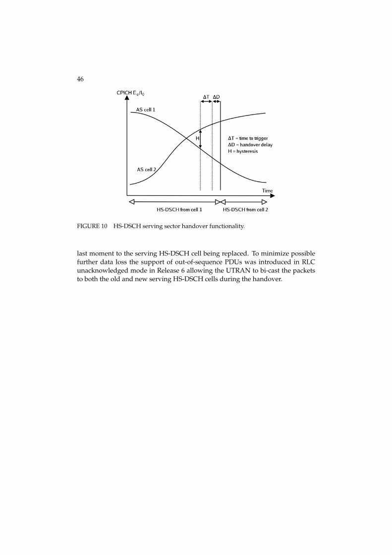
46
FIGURE 10 HS-DSCH serving sector handover functionality.
last moment to the serving HS-DSCH cell being replaced. To minimize possiblefurther data loss the support of out-of-sequence PDUs was introduced in RLCunacknowledged mode in Release 6 allowing the UTRAN to bi-cast the packetsto both the old and new serving HS-DSCH cells during the handover.

3 RECEIVER STRUCTURES
In this chapter the UE reception algorithms are addressed. First the basics of mul-tipath radio channels are presented in chapter 3.1. The conventional rake receiverstructure and the mathematical modeling of it in the system simulator is coveredin chapter 3.2. The problems with intra- and inter-cell interference is explained inchapters 3.3 and 3.4, respectively. As a solution to mitigate these, an advanced UEreception algorithm, linear minimum mean squared error (LMMSE) chip-levelequalizer and its modeling issues are presented in chapter 3.5. More informationon advanced receiver structures can be found e.g. in [Lat99].
3.1 Multipath radio channels
Different reflections, diffractions and attenuation of the transmitted signal energycaused by natural obstacles such as buildings and land forms characterize theterrestrial radio channel. The same signal energy may arrive at the receiver viamultiple different paths at different time instants. This phenomenon defines themultipath power delay profile of the channel. The profile represents a sort oftemporal impulse response of the channel, i.e. the impact of the channel to asignal sent in one symbol time. The received replicas of the same transmittedsignal at different time instants are called taps.
Two example channel power delay profiles used in the simulations of thisthesis are presented in Table 5. The profiles are modified versions of Pedestrian A(PedA) and Vehicular A (VehA) models presented originally by the InternationalTelecommunication Union Radiocommunication Sector (ITU-R) in [ITU97]. Forthe sake of modeling and notational simplicity the profiles are modified so thatthe delays match integer chips.
Fig. 11 depicts two different channel types, a frequency selective and a flatfading channel. Multipath propagation has an effect on the frequency responseof the channel. From the power delay profiles of VehA and PedA it can be seenthat VehA represents a rich scattering environment with several multipaths. This

48
leads to a frequency-selective channel. PedA has a strong tap at zero delay andonly one other weak path. Thus, PedA is more a flat-fading channel.
TABLE 5 Channel profile power delay profiles.
Channel profile Path delays [slots]VehA 0 1 3 4 7 10PedA 0 1
Path powers [dB]VehA -3.1 -5.0 -10.4 -13.4 -13.9 -20.4PedA -0.2 -13.5
FIGURE 11 Frequency selective and flat fading radio channels.
The taps are detected by sampling the channel at regular intervals. Themaximum sampling interval of the WCDMA receiver is the chip duration. Whenusing oversampling the receiver samples the channel more than once during asingle chip duration. In this thesis no oversampling is assumed. Fig. 12 presentsa multipath radio channel profile where the second and the third tap arrive at thereceiver within the same chip-time. Without oversampling the WCDMA receivercannot distinguish them and their energy is combined to form a single tap. If thetap phases are different, they can be combined destructively. This effect manifestsitself as signal cancellation called fast fading.
The occurrence of fast fading is dependent on the lengths of the signal paths.If two signal paths have a length difference of more than 78 meters (= speed oflight ÷ chip rate = 3.0 × 10⁸ m/s ÷ 3.84 Mcps), they arrive at the receiver at twodifferent chip-times and can be separated. If the path length difference is shorter,they arrive at the same chip duration and are seen as single tap, if they do notcancel each other out.

49
FIGURE 12 Example of a multipath radio channel.
3.1.1 Mathematical modeling of multipath radio channel
If it is assumed that there exists NRx Rx-antennas at UE the received chip se-quence y equals
y = HTx + n , (4)
where H is the channel matrix between the transmitter and the receiver and thetransmitted chip stream x is
x = [x[t + F + L − D] · · · x[t] · · · x[t − D]]T (5)
and n is the noise vector consisting of the both the neighboring sector interferenceand the thermal noise over the bandwidth. Here F is the length of the linearfilter, which models the receiver. The calculation of filter coefficients is discussedin chapter 3. D is the delay parameter satisfying (0 ≤ D ≤ F) and L is thedelay spread of the channel normalized to the chip interval. Multiplication by the(F + L)× (F × NRx) channel coefficient matrix H in Eq. 4 models the convolutionbetween the transmitted chips and the impulse response of the channel. Thus,
H =
⎡⎢⎢⎢⎢⎣
hNRx×(L+1)0NRx×1 · · · 0NRx×1
0NRx×1 hNRx×(L+1)· · · ...
...... . . . 0NRx×1
0NRx×1 0NRx×1 0NRx×1 hNRx×(L+1)
⎤⎥⎥⎥⎥⎦
T
, (6)
where h is the NRx × (L + 1) channel impulse response matrix defined by
h =
⎡⎢⎢⎢⎣
h1[0] h1[1] · · · h1[L]h2[0] h2[1] · · · h2[L]
...... . . . ...
hNRx [0] hNRx [1] · · · hNRx [L]
⎤⎥⎥⎥⎦ , (7)
where hi[l] is the channel impulse of ith Rx-antenna at delay l.

50
Signal reception
Using the signal model presented in chapter 3.1.1 the receiver can be defined witha F × NRx chips long linear filter w which is used to obtain the chip estimate x̃ forthe transmitted chip sequence x i.e.
x̃ = wTy . (8)
The signal-to-interference and noise ratio at the output of a linear filter maythen be calculated by evaluating the power of the specific signal and noise termsafter the filtering as in [Kom00, Luc03]. These methods can directly be appliedwhen calculating the signal to interference and noise ratio (SINR) at the output ofthe linear receiver. Thus,
SINR =Sf Pch|wTHTδD|2
PtotwTHT δ̂D δ̂TDH∗w∗ + wTCww∗ , (9)
where S f is the channel spreading factor, Pch is the channel transmit power andPtot is the total transmit power of the sector and
δD =[
0 · · · 0 1 0 · · · 0]T , (10)
which represents the delay of the equalizer. The left-most term in the divisormodels the intra-cell interference (i.e. inter-path interference) and right-mostterm models the inter-cell interference and background noise. SINR is calculatedaccording to Eq. 9 for all linear receivers and the definition of w varies accordingto the linear receiver type used. Moreover, in Eq. 9 δ̂D is a (F × F) matrix definedby
δ̂D = diag([
1 · · · 1 0 1 · · · 1]) (11)
and it is used in the matrix product HT δ̂D δ̂TDH∗ to extract the elements from the
channel matrix that are used in the inter-path interference calculation.In Eq. 9 the (F × NRx) × (F × NRx) interference matrix
Cw =
⎡⎢⎢⎢⎢⎢⎢⎢⎢⎣
σ21 0 0 0 0 0
0 . . . 0 0 0 00 0 σ2
NRx0 0 0
0 0 0 σ21 0 0
0 0 0 0 . . . 00 0 0 0 0 σ2
NRx
⎤⎥⎥⎥⎥⎥⎥⎥⎥⎦
, (12)
whereσ2
j = I jtot − I j
i , (13)
if the interference is assumed to be uncorrelated between the receive antennas.The antenna-wise total downlink interference from all sectors to UE in Eq. 13 iscalculated as
I jtot =
k
∑i=1
I ji + N0 , (14)

51
where k is the number of sectors in the simulation area and N0 is thermal noise.Finally, the downlink interference from one sector to observed UE is calculatedas
I ji = PiLi
Ni
∑l=1
(gi,l‖hji,l‖2), (15)
where Pi is the downlink transmission power in the sector i and Li is the slowfaded path loss between the UE and sector i. Ni is the number of multipath com-ponents provided by the simulated environment in sector i, gi,l is the averagepath gain of the lth component and hj
i,l is complex channel coefficient for sector i,multipath component l and receive antenna j.
3.2 Rake receiver
If several taps arrive at the receiver more than one chip-time apart, these signalscan be separated and combined coherently in WCDMA. This is called multipathdiversity. Using the rake reception algorithm the multipaths can be combined andmultipath diversity obtained. The phases of rake reception algorithm is describedshortly in the following [Hol04].
1. Received taps are identified from the signal.
2. Correlation receivers, a.k.a. rake fingers are allocated to each tap.
3. Phase shift induced by the channel for each finger is tracked using a channelestimation formed from the pilot symbol
4. Phase shifts are reversed.
5. Fingers are combined coherently.
The presented signal combining algorithm is also called Maximum Ratio Com-bining (MRC). A block diagram of example three finger rake receiver is presentedin Fig. 13. Digitized input samples are received in the form of I and Q branches.Code generators and a correlator perform the despreading and integration to userdata symbols. The phase rotator removes the channel effect to the received fin-gers with the channel estimate provided by the channel estimator. The delay iscompensated by the difference in arrival times of the symbols in each finger. Thechannel compensated symbols are then combined by the rake combiner therebyproviding multipath diversity against fading. The matched filter is used for de-termining and updating the current multipath delay profile of the channel. Thismeasured delay profile is then used to assign the rake fingers to the largest peaks[Hol04].
Multiple receive antennas can be applied by just adding additional rake fin-gers to the antennas. This is the same as multiple paths received from a singleantenna. Thus, all the energy from multiple paths and antennas can be received.
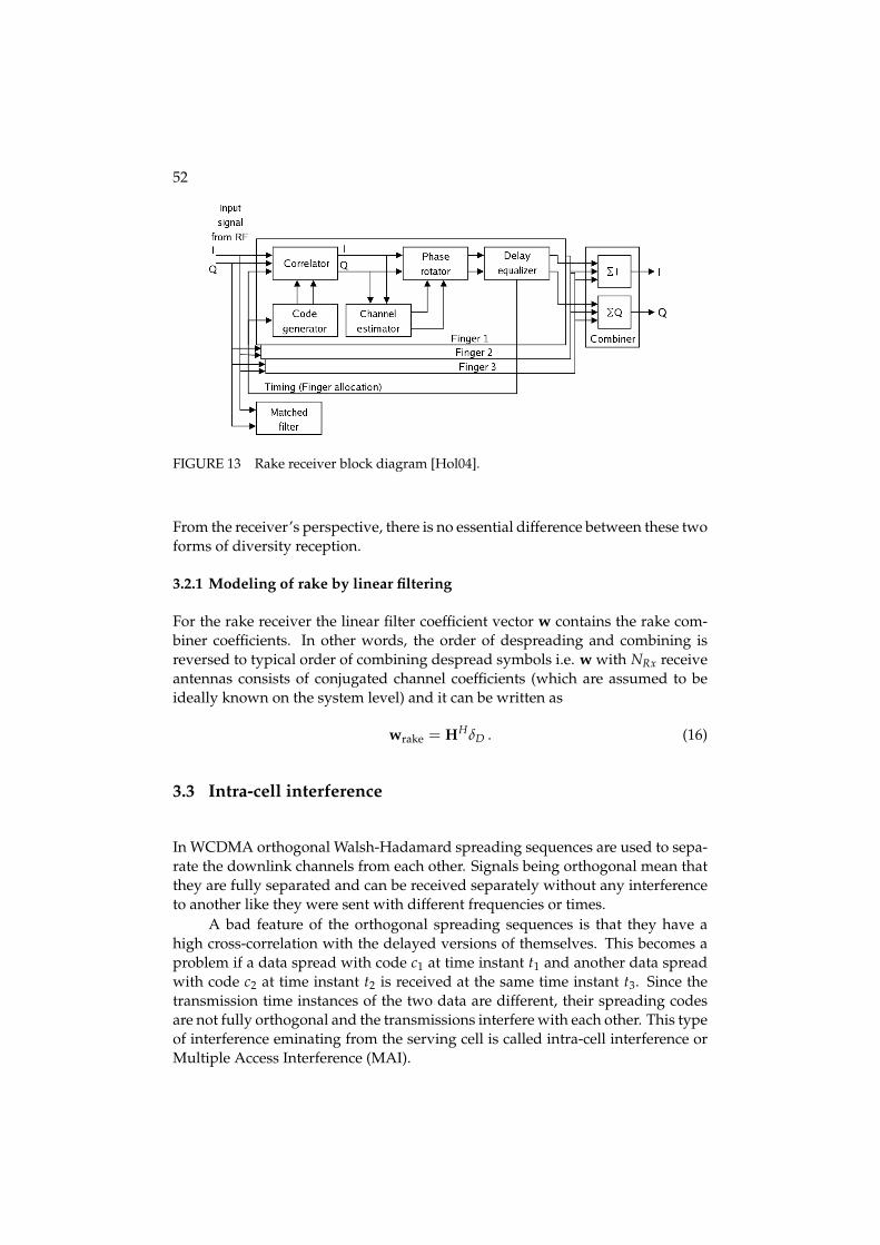
52
FIGURE 13 Rake receiver block diagram [Hol04].
From the receiver’s perspective, there is no essential difference between these twoforms of diversity reception.
3.2.1 Modeling of rake by linear filtering
For the rake receiver the linear filter coefficient vector w contains the rake com-biner coefficients. In other words, the order of despreading and combining isreversed to typical order of combining despread symbols i.e. w with NRx receiveantennas consists of conjugated channel coefficients (which are assumed to beideally known on the system level) and it can be written as
wrake = HHδD . (16)
3.3 Intra-cell interference
In WCDMA orthogonal Walsh-Hadamard spreading sequences are used to sepa-rate the downlink channels from each other. Signals being orthogonal mean thatthey are fully separated and can be received separately without any interferenceto another like they were sent with different frequencies or times.
A bad feature of the orthogonal spreading sequences is that they have ahigh cross-correlation with the delayed versions of themselves. This becomes aproblem if a data spread with code c1 at time instant t1 and another data spreadwith code c2 at time instant t2 is received at the same time instant t3. Since thetransmission time instances of the two data are different, their spreading codesare not fully orthogonal and the transmissions interfere with each other. This typeof interference eminating from the serving cell is called intra-cell interference orMultiple Access Interference (MAI).

53
FIGURE 14 Multiple access interference.
Fig. 14 presents the occurrence of MAI caused by the multipath propaga-tion of the own channel signal. Although rake receiver can exploit the multipathdiversity by finding and combining taps of the same transmission arriving atthe receiver during several chip-times, the delayed versions of the desired signalcause interference at the same time. Other channels transmitted by the servingcell interfere the signal as well but are not depicted in the figure. The problemof compromised orthogonality of the spreading codes occurs only in frequency-selective channels, where several taps are received more than one chip-time apart.In a flat-fading channel only a single tap arrives at the receiver, i.e. a sent signal isreceived only once. Therefore, a similar problem with the signal delays does notexist and the channels remain orthogonal. However, frequency-selective chan-nels where MAI is a problem are very common in WCDMA networks and thusadvanced algorithms targeting to mitigate intra-cell interference are beneficial.
3.4 Inter-cell interference
The different scrambling codes, channel states and angles-of-arrivals (AOA) ofthe neighboring base station signals affect the characteristics of the inter-cell in-terference, which is dominant in cell border regions. The long scrambling codesthat are used to separate different base station signals are not orthogonal. Thus,inter-cell interference is present regardless of the delay profile of the radio chan-
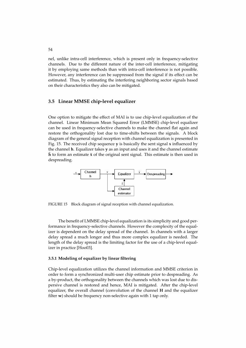
54
nel, unlike intra-cell interference, which is present only in frequency-selectivechannels. Due to the different nature of the inter-cell interference, mitigatingit by employing same methods than with intra-cell interference is not possible.However, any interference can be suppressed from the signal if its effect can beestimated. Thus, by estimating the interfering neighboring sector signals basedon their characteristics they also can be mitigated.
3.5 Linear MMSE chip-level equalizer
One option to mitigate the effect of MAI is to use chip-level equalization of thechannel. Linear Minimum Mean Squared Error (LMMSE) chip-level equalizercan be used in frequency-selective channels to make the channel flat again andrestore the orthogonality lost due to time-shifts between the signals. A blockdiagram of the general signal reception with channel equalization is presented inFig. 15. The received chip sequence y is basically the sent signal x influenced bythe channel h. Equalizer takes y as an input and uses it and the channel estimateh̃ to form an estimate x̃ of the original sent signal. This estimate is then used indespreading.
FIGURE 15 Block diagram of signal reception with channel equalization.
The benefit of LMMSE chip-level equalization is its simplicity and good per-formance in frequency-selective channels. However the complexity of the equal-izer is dependent on the delay spread of the channel. In channels with a largerdelay spread a much longer and thus more complex equalizer is needed. Thelength of the delay spread is the limiting factor for the use of a chip-level equal-izer in practice [Hoo03].
3.5.1 Modeling of equalizer by linear filtering
Chip-level equalization utilizes the channel information and MMSE criterion inorder to form a synchronized multi-user chip estimate prior to despreading. Asa by-product, the orthogonality between the channels which was lost due to dis-persive channel is restored and hence, MAI is mitigated. After the chip-levelequalizer, the overall channel (convolution of the channel H and the equalizerfilter w) should be frequency non-selective again with 1 tap only.

55
If the LMMSE solution in [Kra00a, Kra00b] is applied, the equalizer coeffi-cient vector is
wLMMSE = C−1w HH(HC−1
w HH + I)−1δD . (17)
Note that delay can be optimized for LMMSE as in [Kra00a].
3.5.2 Interference aware equalizer
With the signal model presented in Eq. 4 only the own sector channel is assumedto be known and thus the equalizer is able to mitigate only the intra-cell interfer-ence. Due to the random scrambling codes used at the interfering base stationsthe inter-cell interference is assumed as white Gaussian noise having a knownvariance at the receiver.
With interference aware equalizer, the channels between the UE and itsstrongest interfering sectors (which give the highest contribution to inter-cell in-terference seen by the UE) are assumed to be known. Thus, the channel matricesfor those sectors are constructed also and the received signal is filtered with equal-izer coefficients. Note that sector index j in Eq. 18-21 and in Eq. 25-26 representshow strong the interference power from UE point of view is, i.e. the lower theindex, the stronger the interference power. Hence, indexes between [1, NIBS] re-fer to the strongest interfering base stations (sectors) taken into account. Sectorswith indexes between [NIBS + 1, k] assume white interference model, where k isthe total number of sectors in the simulation area. Thus, the signal model withthe partially colored inter-cell interference becomes
y = HTx +NIBS
∑j=1
(HT
j xj
)+ n , (18)
where Hj and xj are the channel matrix and the transmitted bit sequence of theinterfering base station j, respectively.
Linear filter coefficients
With interference aware LMMSE equalizer (I-LMMSE) the linear filter coefficientvector w is calculated using the inverse of the covariance matrix Crr.
wI-LMMSE = C−1rr MHδD , (19)
where the (FNRx) × (F + L) matrix M is defined by
M =
⎡⎢⎣ HH
1...
HHNRx
⎤⎥⎦ , (20)
where Hi is the own sector channel matrix from receive antenna i. Matrix M forthe interfering base stations can be constructed correspondingly. The (FNRx) ×(FNRx) covariance matrix Crr is defined as

56
Crr = PtotMMH +NIBS
∑j=1
Ptot,jMjMHj + σ2I, (21)
where Ptot and Ptot,j are the total Tx powers of the serving sector and interferingsector j, respectively. The white noise interference term
σ2I =
⎡⎢⎣
I1 . . . 0
0 . . . 0... 0 INRx
⎤⎥⎦ , (22)
where Ii is the F × F white noise interference matrix of receive antenna i definedby
Ii =
⎡⎢⎣
σ2i . . . 0
0 . . . 0... 0 σ2
i
⎤⎥⎦ , (23)
where σ2i is the noise power of receive antenna i.
SINR calculation
The SINR calculation using white inter-cell interference was presented in Eq. 9.Extension to colored noise can be derived from Eq. 18:
SINR =Pch∣∣wTHTδD
∣∣2PtotwTHT δ̂D δ̂T
DH∗w∗ + Icolor + wTCww∗ , (24)
where Icolor is the colored interference of NIBS strongest base stations and is de-fined as
Icolor =NIBS
∑j=1
Ptot,jwTHTj H∗
j w∗ . (25)
The interference matrix Cw is otherwise similar to that in Eq. 12 but with thismodel the sectors which interference is calculated explicitly are removed fromthe white noise term as their contribution to inter-cell interference is modeledrealistically. Thus, the calculation of total downlink interference to UE antenna ifrom all sectors which interference is assumed white is now defined by
Iitot =
k
∑j=1+NIBS
Iij + N0, (26)
where k is the number of sectors in the simulation area and N0 is thermal noise.

4 ANTENNA DIVERSITY
Signal fading causes such large problems in wireless systems that the dependenceof just a single signal path can lead to significant performance degradation. Oneoption to mitigate the effect of signal fading is to use repetition in time domain.This is a sort of insurance in case the channel is in a bad condition at the time ofsignal transmission. By transmitting the signal also another time decreases theprobability that the signal is totally lost. If one signal is lost, there still exists acopy or copies of the same signal and the signal can be recovered. Repetition ofthe signal in time is called time diversity.
If the data transmission is very delay sensitive, it might not be possible touse time diversity because the transmission of identical copies of the same signaldecreases the transmission rate of the new data. Therefore there is a need foralternative method to achieve the same diversity order but not at the cost of thedata rate. One option to achieve this is to use spatial diversity, i.e. to transmit andreceive multiple copies of the same data at the same time in different locations.
The way to achieve spatial diversity in wireless systems is to use multipletransmit and receive antennas. Channel fading is dependent on the spatial at-tributes of the signal path between a transmit antenna and receive antenna. Ifantennas are located sufficiently far apart and there are enough differences in thescattering environment of the transmitted signals, each of them fades indepen-dently. Thus, it is beneficial to offer multiple transmission paths to the signal inorder to combine more or less deteriorated signal copies at the receiver to formone sufficiently good signal.
The order of diversity is dependent on the amount of transmit antennasNTx and receive antennas NRx so that the diversity order is NTx × NRx. Whensolely receive diversity is used, the scheme is referred to in this thesis as 1 ×NRx scheme, where NRx > 1. A scheme with mere transmit diversity is referredcorrespondingly NTx × 1. A scheme which employs both receive and transmitantenna diversity (NTx × NRx) provides additional gain to 1 × NRx and NTx × 1schemes. As there are significant differences between utilization of transmit andreceive antenna diversity, they will be discussed separately.
Fig. 16 presents the antenna diversity cases studied in this thesis. Maximum
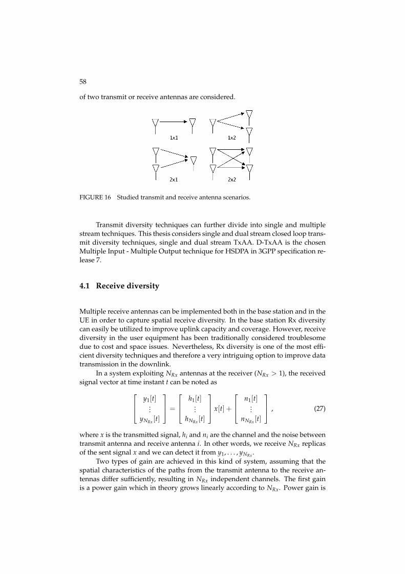
58
of two transmit or receive antennas are considered.
FIGURE 16 Studied transmit and receive antenna scenarios.
Transmit diversity techniques can further divide into single and multiplestream techniques. This thesis considers single and dual stream closed loop trans-mit diversity techniques, single and dual stream TxAA. D-TxAA is the chosenMultiple Input - Multiple Output technique for HSDPA in 3GPP specification re-lease 7.
4.1 Receive diversity
Multiple receive antennas can be implemented both in the base station and in theUE in order to capture spatial receive diversity. In the base station Rx diversitycan easily be utilized to improve uplink capacity and coverage. However, receivediversity in the user equipment has been traditionally considered troublesomedue to cost and space issues. Nevertheless, Rx diversity is one of the most effi-cient diversity techniques and therefore a very intriguing option to improve datatransmission in the downlink.
In a system exploiting NRx antennas at the receiver (NRx > 1), the receivedsignal vector at time instant t can be noted as⎡
⎢⎣ y1[t]...
yNRx [t]
⎤⎥⎦ =
⎡⎢⎣ h1[t]
...hNRx [t]
⎤⎥⎦ x[t] +
⎡⎢⎣ n1[t]
...nNRx [t]
⎤⎥⎦ , (27)
where x is the transmitted signal, hi and ni are the channel and the noise betweentransmit antenna and receive antenna i. In other words, we receive NRx replicasof the sent signal x and we can detect it from y1, . . . , yNRx .
Two types of gain are achieved in this kind of system, assuming that thespatial characteristics of the paths from the transmit antenna to the receive an-tennas differ sufficiently, resulting in NRx independent channels. The first gainis a power gain which in theory grows linearly according to NRx. Power gain is

59
achieved because of the fact that the one sent signal energy is received by NRxantennas and the received powers can be combined.
Another gain is diversity gain. This gain comes from the assumption thatthe transmitted signal fades independently in every path between the transmitantenna and NRx receive antennas. This leads to decreased probability that theoverall received signal gain is low.
However, the diversity gain is only applicable when all the NRx signal pathsfade independently. If the paths are completely correlated, then only the powergain is achieved with receive diversity.
4.2 Transmit diversity
The utilization of transmit diversity mainly increases the transmitter complex-ity without the need for drastic hardware changes at the receiver. Hence, a sig-nificant effort has been devoted in 3GPP to develop efficient transmit diversitysolutions to enhance downlink capacity.
When NTx transmit antennas (NTx > 1) and only one receive antenna isused, the situation is more complicated than in a mere receive diversity scheme.One can’t just transmit the same signal at the same time from all transmit anten-nas although all the signal paths would fade independently. Due to the fact thatthe antennas share the base station power, the transmitted signals have 1/NTx ofthe power of the base station and thus no power gain would be attained at thereceiver.
Diversity gain can be attained with transmit diversity by transmitting thesame symbol at different times from different antennas. This means that onlyone antenna transmits at a time instance and the rest are silent. This however ismere repetition and does not utilize the whole potential of the additional transmitantennas. As it is not feasible to send the same symbol at the same time instantfrom several antennas, the gain of multiple antennas can be achieved by sendingmore than one symbol at a time.
When using two transmit antennas, space-time block codes can be used toachieve gain over mere time diversity without any knowledge of the channel.Additionally, when the channel state information is present, transmit diversitycan provide quite significant gains over one branch transmission.
4.2.1 Space time transmit diversity (STTD)
The simplest and probably the most known space-time block coding scheme isthe Alamouti scheme [Ala98] or space time transmit diversity (STTD) which sup-port is mandatory for the UE in UMTS [3G05]. The block diagram of STTD oper-ation with single receiver antenna is presented in Fig. 17.
STTD operation can be summarized as follows ([Ala98], [Tse05], [Hot03]). InSTTD two symbols x1 and x2 are sent at one symbol period over antennas 1 and

60
FIGURE 17 STTD transmit diversity operation block diagram [Ala98].
2, respectively. The same symbols are sent again in the next symbol period butthey are coded so that they are orthogonal at the receiver and can be combinedwith the symbols received during the first period thus achieving both diversityand power gain. At time instant 2, antenna 1 sends −x∗2 and antenna 2 sendsx∗1. Let’s assume that the channels remain constant over two symbols periods, i.e.hi = hi[1] = hi[2], i = 1, 2. The received signal y at time instants 1 and 2 can bewritten as [
y[1]y[2]
]=
1√2
[x1h1 + x2h2x∗1h2 − x∗2h1
]+[
n[1]n[2]
], (28)
where hi represents the channel gain from transmit antenna i to receive antennaand n is the noise. The received symbol matrix is normalized by 1√
2so that the
same power is used for STTD transmission as would be used if the symbols wereindependently transmitted from one antenna. Conjugating the received signalduring the second symbol period the received signal equation can be written as
[y[1]y[2]∗
]= H
[x1x2
]+[
n[1]n[2]∗
], (29)
where
H =1√2
[h1 h2h∗2 −h∗1
]. (30)
The space-time matched filtering proceeds by applying the Hermitian con-jugate H on the received signal:

61
HH[
y[1]y[2]∗
]=[
x̃1x̃2
]=
12
(|h1|2 + |h2|2
) [ x1x2
]+[
n[1]n[2]∗
](31)
By employing space-time block coding the transmitted symbols pass throughorthogonal channels which do not interfere with each other. Thus, the energyused on the symbols during two transmit periods can be combined forming space-time matched filter soft outputs x̃1 and x̃2. They can then be used as input forthe hard decision maker e.g. maximum likelihood sequence detector which ulti-mately forms the transmitted symbol estimates x̂1 and x̂2.
As the transmit power is divided into two symbols, we do not get the sim-ilar power gain as in receive diversity, where the received power was linearlydependent on the number of receive antennas. Using STTD we get power gainover repetition coding as lower power is needed per symbol.
Channel model and SINR calculation with STTD
STTD operation changes the channel coefficient matrix definition of the generalsignal model presented in chapter 3.1.1. As two transmit antennas are used andtwo separate signals are transmitted, they have to be taken into account. Hence,the channel matrix definition becomes
H =[
H1H2
]. (32)
Two receiver filters w1 and w2 are used in computing separately the twoSINRs, noted as S1/I1 and S2/I2. Filters are defined similarly for both Rake andLMMSE equalizer as defined in chapter 3. After STTD decoding, only one SINRis obtained.
The form of instantaneous SINR of antenna i has the form
Si
Ii=
S f PHS−DSCH|wTi HT
i δD|2|wT
i HTi δ̂D|2︸ ︷︷ ︸
Iintra
+ |wTi HT
j δ̂D|2︸ ︷︷ ︸Ij
+ wTi σ2
nw∗i︸ ︷︷ ︸
Iinter
, (33)
where j = 2 when i = 1 and vice versa, Sf is the spreading factor, PHS-DSCH is theHS-DSCH transmit power, Iintra is the intra-cell interference and Ij is the interfer-ence from antenna j. Iinter is the inter-cell interference consisting of neighboringcell interference and also the system noise.
We denote the convolution between the channel coefficients (ci, i = 1, 2)and the filter coefficients (wi, i = 1, 2) with a1 and a2, having the form of ai =ci ⊗ wi, i = 1, 2, where ⊗ denotes the convolution operation. The final SINRafter decoding contains the contribution of antenna 1 weighted by a1 and alsothe contribution of antenna 2 weighted by a2. Thus, the ratio between the signalcomponent S and the interference component I will express the final SINR.
An intuitive form of the received signal might be expressed as

62
r = a1(√
S1x + n1) + a2(√
S2x + n2), (34)
where x is the amplitude of the combined received signal, n1 and n2 are the cor-responding noise levels and i is the Tx antenna index. Due to the coherent com-bining of the signal components S1 and S2 and also due to the non-coherent com-bining of the interference component I1 and I2, the SINR is expressed as
SINR =SI
=(a1
√S1 + a2
√S2)2
a21 I1 + a2
2 I2. (35)
4.2.2 Closed loop transmit diversity
Channel state information (CSI) can be utilized effectively if it is known at thetransmitter before transmission. By knowing the effect of the channel to trans-mitted signal it can be reduced or even canceled. However, to achieve CSI thetransmitter needs constant feedback from the receiving entity.
Generally, in closed loop transmit diversity (CLTD) a signal is transmittedduring one symbol period from all transmit antennas. The phases of the signalssent from each antenna are weighted according to the receiver feedback in orderto exploit the phase shift caused by the channel and to turn its effect in favor.
When the expected phase shift is known the sent signal phases can be al-tered the way that all sent signals arrive at the receiver in-phase and thus theycan be combined constructively. The form of the received signal y at time instantt can be written as
y[t] =
(NTx
∑i=1
wi[t]hi[t]
)x[t] + n[t] , (36)
where wi[t] is the applied complex weight and hi[t] is the channel impact betweenthe receiver and transmit antenna i at time instant t. In this thesis only the twotransmit antenna scheme is considered. When two transmit antennas are used theweight applied to antenna 1 remains constant and only the phase of the secondantenna is altered. Ideally, weight w2 should be selected so that the phases ofw1[t]h1[t] and w2[t]h2[t] are the same.
The correct behavior of closed loop transmit diversity demands that thechannel state information is correct and up to date. Many phenomenons degradethe performance of CLTD. Firstly, feedback is subject to errors due to uplink chan-nel imperfections. Incorrect feedback results in incorrect phase shifts of the sec-ond signal and the received signals can be combined destructively at the receiver.Also, there is a delay between the measurement of the channel in the receiver andthe usage of the CSI. If the channel changes rapidly, the CSI is not up to date andbecomes useless. Therefore, the coherence time of the channel must be longerthan the feedback delay. Closed loop transmit diversity might not give gain withhigh mobile velocities due to rapid channel variations.

63
FIGURE 18 Single stream TxAA operation block diagram [3G04a].
4.2.3 Single stream Transmit Antenna Array (TxAA)
Single stream TxAA (or Closed Loop Mode 1) operation block diagram for twotransmit antennas is presented in Fig. 18. There the transmitted pilot signals fromantennas 1 and 2 are weighted with the antenna specific weighting factor w1 andw2, respectively. The signals pass through multipath fading downlink channel.The receiving entity calculates the optimal factor w2 for transmit antenna 2 fromthe received signals. The weight is then sent to the transmitter. As there are only alimited amount of feedback bits available to be used in realistic implementationsof CLTD, the amount of phase rotation possibilities is also limited. In TxAA theweight for antenna 1 is constant 1/
√2 and for antenna 2 the weight w2 used in
slot t + 1 is calculated from two consecutive feedback bits sent by the UE so that
w2[t + 1] = 1/√
2ejφ[t] , (37)
whereφ[t] = arg(j t mod 2 sgn(y[t]) + j (t−1) mod 2 sgn(y[t − 1])) , (38)
where y[t] is the feedback command received in slot t [Hot03]. The sign functionin Eq. 38 is used to quantize each received feedback bit. Simplified, each feedbackbit represents either the real or the imaginary part of the feedback weight. Thebase station constructs the feedback weight by filtering the feedback bits over twoslots using a sliding window. The resulted phase constellation has four states.Since all consecutive feedback weights use one common feedback bit, the nexttransmit weight either remains unchanged from the previous or jumps to theneighboring state, as shown in Fig. 19.
Feedback weight verification
As mentioned earlier, the sent feedback bits are prone to errors when transmittedthrough the uplink channel. This is due to the fact that the bits are sent uncoded
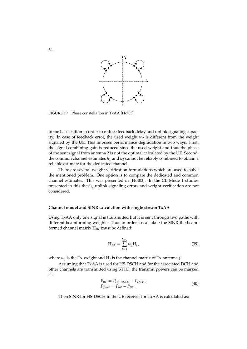
64
FIGURE 19 Phase constellation in TxAA [Hot03].
to the base station in order to reduce feedback delay and uplink signaling capac-ity. In case of feedback error, the used weight w2 is different from the weightsignaled by the UE. This imposes performance degradation in two ways. First,the signal combining gain is reduced since the used weight and thus the phaseof the sent signal from antenna 2 is not the optimal calculated by the UE. Second,the common channel estimates h1 and h2 cannot be reliably combined to obtain areliable estimate for the dedicated channel.
There are several weight verification formulations which are used to solvethe mentioned problem. One option is to compare the dedicated and commonchannel estimates. This was presented in [Hot03]. In the CL Mode 1 studiespresented in this thesis, uplink signaling errors and weight verification are notconsidered.
Channel model and SINR calculation with single stream TxAA
Using TxAA only one signal is transmitted but it is sent through two paths withdifferent beamforming weights. Thus in order to calculate the SINR the beam-formed channel matrix HBF must be defined:
HBF =NTx
∑j=1
wjHj , (39)
where wj is the Tx-weight and Hj is the channel matrix of Tx-antenna j.Assuming that TxAA is used for HS-DSCH and for the associated DCH and
other channels are transmitted using STTD, the transmit powers can be markedas:
PBF = PHS-DSCH + PDCH ,Pomni = Ptot − PBF .
(40)
Then SINR for HS-DSCH in the UE receiver for TxAA is calculated as:

65
SINR =S f PHS-DSCH|wTHT
BFδD|2PBF|wTHT
BF δ̂D|2︸ ︷︷ ︸Iintra
+Iomni + wTCww∗︸ ︷︷ ︸Iinter
, (41)
where receiver filters for both Rake and LMMSE equalizer are defined otherwisesimilarly as in chapter 3 but the beamformed channel matrix is used in the filtercoefficient calculation. Multipath interference from the non-beamformed chan-nels (omni-interference) is defined as
Iomni =12· PomniwT(
NTx
∑n=1
HTn δ̂D δ̂T
DH∗n)w∗ . (42)
Explicit modeling of inter-cell interference
Iinter in Eq. 41 presents the inter-cell interference contribution. Note that the im-pact of set/changed Tx-weights in the neighboring sectors can be modeled ex-plicitly.
Taking into account that TxAA is used also in the neighboring sectors, thetotal downlink interference from sector i can be divided into beamformed andnon-beamformed interference. The total power Ptot,i from sector i excluding com-mon pilot power is assumed to be weighted according to the current HSDPA userin sector i and only common pilot power is assumed to cause non-beamformedinterference. Thus beamformed interference from sector i is given as
IBFi,j =
12(Ptot,i − Ppilot)Li
Ni
∑l=1
(gi,l
(‖w1,ih
j1,i,l + w2,ih
j2,i,l‖2
)), (43)
where Ptot,i is the total downlink transmission power and Ppilot is common pilotpower in sector i and Li is the slow faded path loss between the terminal andsector i. Ni is the number of multipath components provided by the simulatedenvironment without diversity in sector i, gi,l is the average path gain of the lth
component, hj1,i,l and hj
2,i,l are the complex channel coefficients for two Tx anten-nas of sector i, receive antenna j and multipath component l. w1,i and w2,i aretransmit weights for antennas 1 and 2 in sector i for the scheduled HSDPA user.n0 is thermal noise.
Interference from common pilot channel is given as
Iomnii,j =
12
PpilotLi
Ni
∑l=1
(gi,l
(‖hj
1,i,l‖2 + ‖hj2,i,l‖2
)). (44)
This leads to total downlink interference from all the sectors as
I jtot =
k
∑i=1
(Iomnii,j + IBF
i,j
)+ n0 . (45)

66
4.2.4 Dual stream TxAA
In 3GPP Release 7 the peak data rate of HSDPA increased by introducing thesupport for MIMO usage with HS-DSCH. 3GPP extended the TxAA transmitdiversity scheme of Release 99 WCDMA to a full MIMO approach includingspatial multiplexing. The approach is called D-TxAA. With D-TxAA up to twodata streams (transport blocks) can be transmitted simultaneously over the radiochannel using the same channelization codes. Each transport block is processedand channel coded separately. After spreading and scrambling, the transmittedstreams are precoded based on weight factors to optimize the signal for transmis-sion over the radio channel.
Generally in D-TxAA the UE data in the transmission buffer at the Node Bcan be sent through either one or two independent data streams on the physicallayer. The UE measures the channel quality between all Tx antennas and the UEseparately. Separate CQIs are sent for single stream mode and both streams fordual stream mode.
As the Node B schedules the UEs a transmission mode (single or dual stream)which maximizes the achievable throughput is selected. The Node B informsthe UE of the used transmission format(s) in HS-SCCH. Only a single HS-SCCHtransport block is sent. Node B then allocates independent MCSs for the stream(s)according to the reported CQIs.
The base station weighs the transmitted HS-DSCH signal(s) according to thereceiver feedback and transmits the used precoding weight(s) in HS-SCCH to thereceiver, eliminating the need for antenna verification.
If single stream mode is selected, the D-TxAA falls back to basic TxAA op-eration. In case of dual stream mode the form of the received signal yi of streami at time instant t can be written as
yi[t] =
(NTx
∑j=1
wi+2(j−1)[t]hj[t]
)xi[t] + ni[t] , (46)
where hj[t] is the channel impact between the receiver and transmit antenna j attime instant t. It should be noted that the noise ni[t] includes the interference ofthe parallel stream. Precoding weight wk is selected so that
w1 = w3 = 1/√
(2) ,w4 = −w2 ,
w2 =[
1+j2 , 1−j
2 , −1+j2 , −1−j
2
].
(47)
Fig. 20 presents the generic structure of D-TxAA transmitter. The receiver ispractically the same as with single stream TxAA, shown in Fig. 18. The receiveronly calculates and reports the optimal weight w2.
Fig. 21 presents the achievable throughput of each MCS in single and dualstream mode. All single stream transmissions are allocated a single stream MCS.If scheduler decides to use dual stream transmission for a UE, dual stream MCSsare allocated for both streams according to their individual reported CQIs. Hence

67
FIGURE 20 The generic downlink transmitter structure to support MIMO operation forHS-DSCH transmission.
FIGURE 21 Achievable HS-DSCH throughput with single and dual stream MCSs. Usedmodulation indicated.
if both streams are allocated the highest dual stream MCS, the achievable bit rateis doubled compared to single stream.
Channel model and SINR calculation with dual stream TxAA
In MIMO transmission the receiver consists of two LMMSE equalizer filters, w1and w2, for the primary and for the secondary data stream, respectively. LMMSEsolution [Kra00a, Kra00b] leads to equalizer coefficients
[w1 w2] = C−1w HH
BF(PtotHBFC−1w HH
BF + I)−1δD . (48)
The definition of the coefficients is done similarly as in chapter 3. The combinedbeamformed channel matrix of both transmit antennas HBF is defined by
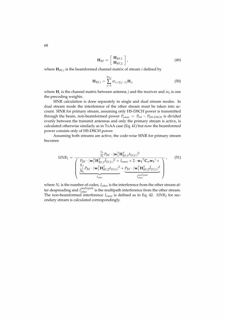
68
HBF =[
HBF,1HBF,2
], (49)
where HBF,i is the beamformed channel matrix of stream i defined by
HBF,i =NTx
∑j=1
wi+2(j−1)Hj, (50)
where Hj is the channel matrix between antenna j and the receiver and wk is onethe precoding weights.
SINR calculation is done separately in single and dual stream modes. Indual stream mode the interference of the other stream must be taken into ac-count. SINR for primary stream, assuming only HS-DSCH power is transmittedthrough the beam, non-beamformed power Pomni = Ptot − PHS-DSCH is dividedevenly between the transmit antennas and only the primary stream is active, iscalculated otherwise similarly as in TxAA case (Eq. 41) but now the beamformedpower consists only of HS-DSCH power.
Assuming both streams are active, the code-wise SINR for primary streambecomes
SINR1 =S fNc
PBF · |wT1 HT
BF,1δD(1)|2⎛⎜⎜⎜⎝
PBF · |wT1 HT
BF,1δ̂D(1)|2 + Iomni + 2 · w1TCww1
∗+S f
NcPBF · |wT
1 HTBF,2δD(1)|2︸ ︷︷ ︸
Iother
+ PBF · |wT1 HT
BF,2δ̂D(1)|2︸ ︷︷ ︸Imultipathother
⎞⎟⎟⎟⎠
, (51)
where Nc is the number of codes, Iother is the interference from the other stream af-ter despreading and Imultipath
other is the multipath interference from the other stream.The non-beamformed interference Iomni is defined as in Eq. 42. SINR2 for sec-ondary stream is calculated correspondingly.
5 ACHIEVED RESULTS
In this chapter the used research method and the research scenario are introducedfirstly in chapters 5.1 and 5.2, respectively. The achieved results are analyzed inchapter 5.3.
5.1 Research tool
The performance evaluation of different receiver schemes along with receive andtransmit antenna diversity is done by means of extensive system simulations us-ing a fully dynamic WCDMA system simulator. The simulator is previously pre-sented in [Häm03]. It is a comprehensive dynamic WCDMA network simulationtool, which is comprised of a detailed model of the physical layer, radio resourcemanagement (RRM) and part of the upper layers of a WCDMA radio access net-work. Also detailed HSDPA and advanced receiver functionality has been addedlater to this system simulator [Kur05].
The conducted simulations are divided into separate link and system levelparts in order to minimize the complexity of the simulator and the simulationtime. In the link level simulations the modeling of the transmission between theNode B and a single terminal is done in a very detailed manner. The resultingdata is used in the system simulations through a so called actual value interface(AVI). The AVI principle has been previously presented in [Häm97].
The overall simulator flow is as follows.
1. Initialization. All static objects are created (simulation scenario, RNCs andNode Bs).
2. Warm up. Some amount of calls are generated to achieve an initial load inthe network.
3. Simulation runs. Calls are being created according to a homogeneous Pois-son process. Power levels, interference and signal to noise ratios are calcu-
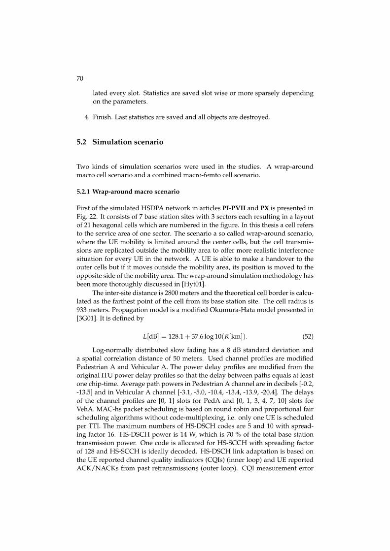
70
lated every slot. Statistics are saved slot wise or more sparsely dependingon the parameters.
4. Finish. Last statistics are saved and all objects are destroyed.
5.2 Simulation scenario
Two kinds of simulation scenarios were used in the studies. A wrap-aroundmacro cell scenario and a combined macro-femto cell scenario.
5.2.1 Wrap-around macro scenario
First of the simulated HSDPA network in articles PI-PVII and PX is presented inFig. 22. It consists of 7 base station sites with 3 sectors each resulting in a layoutof 21 hexagonal cells which are numbered in the figure. In this thesis a cell refersto the service area of one sector. The scenario a so called wrap-around scenario,where the UE mobility is limited around the center cells, but the cell transmis-sions are replicated outside the mobility area to offer more realistic interferencesituation for every UE in the network. A UE is able to make a handover to theouter cells but if it moves outside the mobility area, its position is moved to theopposite side of the mobility area. The wrap-around simulation methodology hasbeen more thoroughly discussed in [Hyt01].
The inter-site distance is 2800 meters and the theoretical cell border is calcu-lated as the farthest point of the cell from its base station site. The cell radius is933 meters. Propagation model is a modified Okumura-Hata model presented in[3G01]. It is defined by
L[dB] = 128.1 + 37.6 log 10(R[km]). (52)
Log-normally distributed slow fading has a 8 dB standard deviation anda spatial correlation distance of 50 meters. Used channel profiles are modifiedPedestrian A and Vehicular A. The power delay profiles are modified from theoriginal ITU power delay profiles so that the delay between paths equals at leastone chip-time. Average path powers in Pedestrian A channel are in decibels [-0.2,-13.5] and in Vehicular A channel [-3.1, -5.0, -10.4, -13.4, -13.9, -20.4]. The delaysof the channel profiles are [0, 1] slots for PedA and [0, 1, 3, 4, 7, 10] slots forVehA. MAC-hs packet scheduling is based on round robin and proportional fairscheduling algorithms without code-multiplexing, i.e. only one UE is scheduledper TTI. The maximum numbers of HS-DSCH codes are 5 and 10 with spread-ing factor 16. HS-DSCH power is 14 W, which is 70 % of the total base stationtransmission power. One code is allocated for HS-SCCH with spreading factorof 128 and HS-SCCH is ideally decoded. HS-DSCH link adaptation is based onthe UE reported channel quality indicators (CQIs) (inner loop) and UE reportedACK/NACKs from past retransmissions (outer loop). CQI measurement error

71
FIGURE 22 Simulation scenario.
standard deviation is 1 dB. Aimed block error rate (BLER) target for the firsttransmission is 30 % and outer loop link adaptation is used to control the BLERtarget. CQI tables are throughput optimized with BLER target of 30 %. Six paral-lel stop-and-wait (SAW) channels are used for the Hybrid ARQ and maximum of4 retransmissions are allowed per transport block. Chase Combining is used forthe retransmissions [Cha85].
Signaling of CQI on the uplink HS-DPCCH is modeled with a fixed delay of1 TTI and with ideal decoding. Probabilities of erroneous acknowledgement in-terpretations are 0.01 (ACK as NACK or DTX as ACK) and 0.001 (NACK as ACK).DTX as ACK (discontinuous transmission) means that no acknowledgement issent due to erroneous reception of HS-SCCH but the transmitter interprets this asan acknowledgement.
Mobility and traffic models are based on [3G98] and default UE velocity is3 km/h. Traffic model is a modified web browsing model in which the users donot have a reading time during a download session i.e. they only have one packetcall per session. Simulation time is 6 minutes. The call arrival rate in the networkis 140 calls per second and the packet call size determined by
PacketSize = min(P, m) , (53)
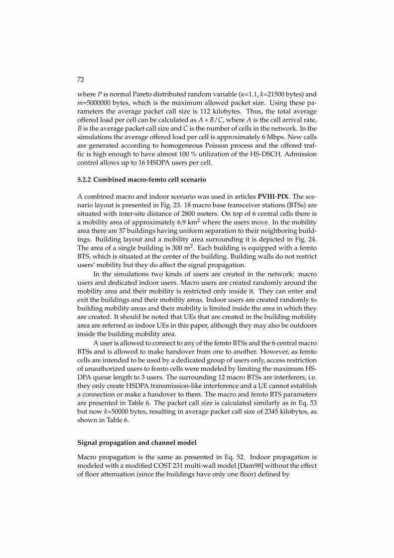
72
where P is normal Pareto distributed random variable (α=1.1, k=21500 bytes) andm=5000000 bytes, which is the maximum allowed packet size. Using these pa-rameters the average packet call size is 112 kilobytes. Thus, the total averageoffered load per cell can be calculated as A ∗ B/C, where A is the call arrival rate,B is the average packet call size and C is the number of cells in the network. In thesimulations the average offered load per cell is approximately 6 Mbps. New callsare generated according to homogeneous Poisson process and the offered traf-fic is high enough to have almost 100 % utilization of the HS-DSCH. Admissioncontrol allows up to 16 HSDPA users per cell.
5.2.2 Combined macro-femto cell scenario
A combined macro and indoor scenario was used in articles PVIII-PIX. The sce-nario layout is presented in Fig. 23. 18 macro base transceiver stations (BTSs) aresituated with inter-site distance of 2800 meters. On top of 6 central cells there isa mobility area of approximately 6.9 km2 where the users move. In the mobilityarea there are 37 buildings having uniform separation to their neighboring build-ings. Building layout and a mobility area surrounding it is depicted in Fig. 24.The area of a single building is 300 m2. Each building is equipped with a femtoBTS, which is situated at the center of the building. Building walls do not restrictusers’ mobility but they do affect the signal propagation.
In the simulations two kinds of users are created in the network: macrousers and dedicated indoor users. Macro users are created randomly around themobility area and their mobility is restricted only inside it. They can enter andexit the buildings and their mobility areas. Indoor users are created randomly tobuilding mobility areas and their mobility is limited inside the area in which theyare created. It should be noted that UEs that are created in the building mobilityarea are referred as indoor UEs in this paper, although they may also be outdoorsinside the building mobility area.
A user is allowed to connect to any of the femto BTSs and the 6 central macroBTSs and is allowed to make handover from one to another. However, as femtocells are intended to be used by a dedicated group of users only, access restrictionof unauthorized users to femto cells were modeled by limiting the maximum HS-DPA queue length to 3 users. The surrounding 12 macro BTSs are interferers, i.e.they only create HSDPA transmission-like interference and a UE cannot establisha connection or make a handover to them. The macro and femto BTS parametersare presented in Table 6. The packet call size is calculated similarly as in Eq. 53but now k=50000 bytes, resulting in average packet call size of 2345 kilobytes, asshown in Table 6.
Signal propagation and channel model
Macro propagation is the same as presented in Eq. 52. Indoor propagation ismodeled with a modified COST 231 multi-wall model [Dam98] without the effectof floor attenuation (since the buildings have only one floor) defined by

73
FIGURE 23 Combined macro and indoor scenario. Building grid and macro mobilityarea (dashed line) depicted at the center.
L[dB] = 37 + 3.2 · 10 log10(R[m]) + Lwnw, (54)
where 37 dB constant is the path loss at reference distance 1 m, R is the distancebetween the transmitter and the receiver in meters, nw is the number of indoorwalls between them and Lw is the attenuation of an indoor wall. Used wall atten-uation parameters along with other main simulation parameters different fromwrap-around macro scenario are presented in Table 7.
In the scenario there are different situations where the UE and the BTS canbe located in relation to each other. The signal propagation must be calculatedindividually in each of them:
• BTS and UE both outdoors: Macro model
• Other outdoors, other indoors: Macro model + external wall loss
• Both indoors and in the same building: Indoor model
• Both indoors but in different buildings: Macro model + 2 × external wall loss
Also the used channel model is twofold, as the UE and BTS locations are con-sidered: if both UE and BTS are in the same building, ITU Pedestrian A channel

74
FIGURE 24 Building layout and building mobility area (dashed line). Femto BTS loca-tion depicted in the center.
TABLE 6 BTS parameters.Macro BTS Femto BTS
No of BTSs 6 serving, 12 interfering 37Site separation 2800 m 467 mAntenna type 3-sector omni-directionalMax Tx power 43 dBm 15 dBmPilot power 33 dBm 4 dBmHS-DSCH power 70 % of total BTS Tx power
HS-SCCH powerPower controlled.
Max. 10 % of total BTS Tx powerMax. HSDPA
16 3queue lengthInterferer Tx power 41.5 dBm -Interferer
80 % -average activity
model is used. Otherwise, the model is Vehicular A. In the sake of modeling sim-plicity both channel model power delay profiles are modified so that the delaysare integer chips.
5.3 Simulation result analysis
The objective of this thesis is firstly to analyze the WCDMA HSDPA network per-formance when advanced receivers, namely LMMSE chip-level linear equalizersare used in UEs. The analysis also extends to different antenna diversity meth-ods thus studying the effect of using receive diversity at the UE and differenttransmit diversity techniques at Node B. Dynamic system level simulations areconducted with different advanced receiver penetrations which are compared tothe results with a basic single rake receiver. Different fading (UE velocity), multi-path propagation conditions (Pedestrian A and Vehicular A channels), radio cell
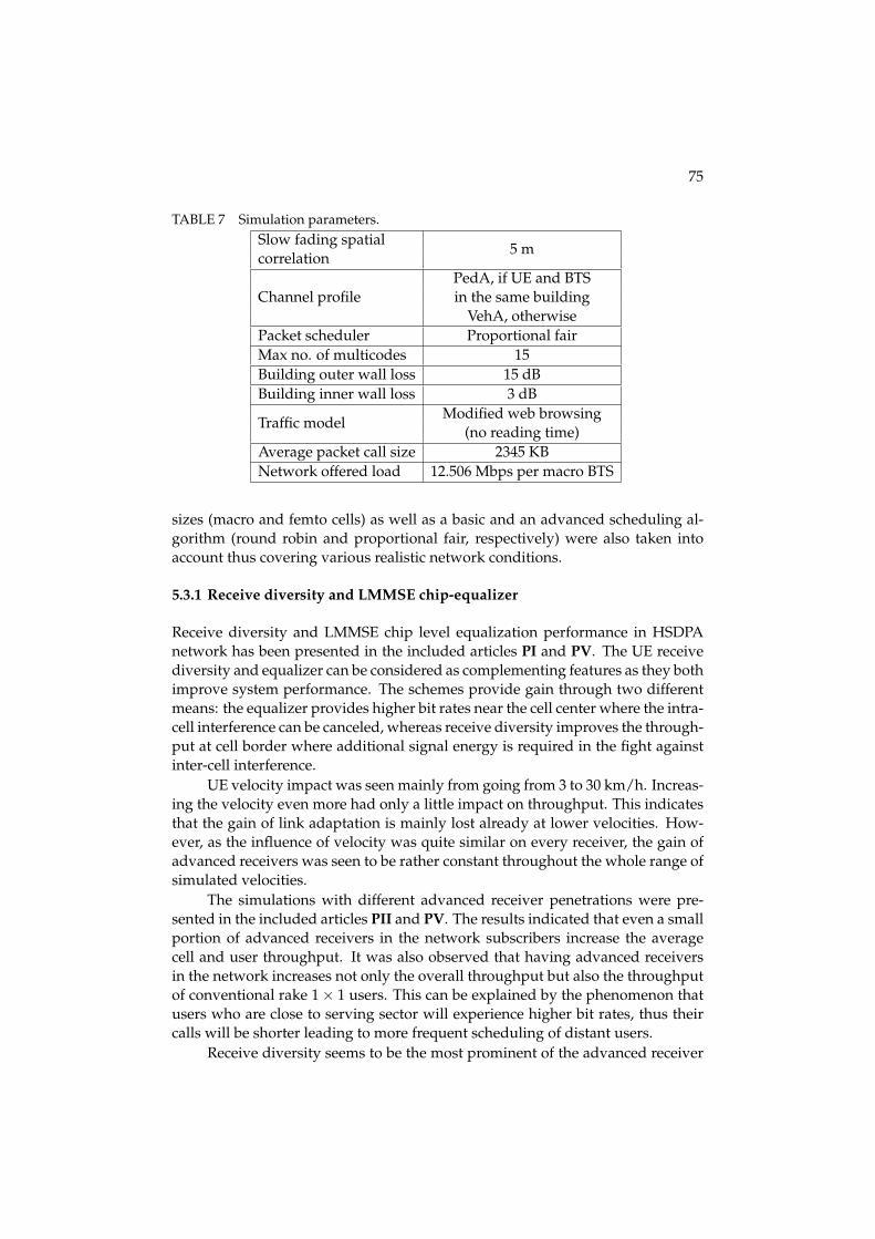
75
TABLE 7 Simulation parameters.Slow fading spatial
5 mcorrelation
Channel profilePedA, if UE and BTSin the same building
VehA, otherwisePacket scheduler Proportional fairMax no. of multicodes 15Building outer wall loss 15 dBBuilding inner wall loss 3 dB
Traffic modelModified web browsing
(no reading time)Average packet call size 2345 KBNetwork offered load 12.506 Mbps per macro BTS
sizes (macro and femto cells) as well as a basic and an advanced scheduling al-gorithm (round robin and proportional fair, respectively) were also taken intoaccount thus covering various realistic network conditions.
5.3.1 Receive diversity and LMMSE chip-equalizer
Receive diversity and LMMSE chip level equalization performance in HSDPAnetwork has been presented in the included articles PI and PV. The UE receivediversity and equalizer can be considered as complementing features as they bothimprove system performance. The schemes provide gain through two differentmeans: the equalizer provides higher bit rates near the cell center where the intra-cell interference can be canceled, whereas receive diversity improves the through-put at cell border where additional signal energy is required in the fight againstinter-cell interference.
UE velocity impact was seen mainly from going from 3 to 30 km/h. Increas-ing the velocity even more had only a little impact on throughput. This indicatesthat the gain of link adaptation is mainly lost already at lower velocities. How-ever, as the influence of velocity was quite similar on every receiver, the gain ofadvanced receivers was seen to be rather constant throughout the whole range ofsimulated velocities.
The simulations with different advanced receiver penetrations were pre-sented in the included articles PII and PV. The results indicated that even a smallportion of advanced receivers in the network subscribers increase the averagecell and user throughput. It was also observed that having advanced receiversin the network increases not only the overall throughput but also the throughputof conventional rake 1 × 1 users. This can be explained by the phenomenon thatusers who are close to serving sector will experience higher bit rates, thus theircalls will be shorter leading to more frequent scheduling of distant users.
Receive diversity seems to be the most prominent of the advanced receiver

76
schemes. Dual antenna receiver with chip-equalization offers the best perfor-mance in all cases. As the impact of different parameters was evaluated, theamount of superiority of the dual antenna receiver with conventional rake overthe conventional single antenna chip-equalizer depends on the selected setting.
5.3.2 Advanced scheduling
Advanced scheduling algorithm, namely proportional fair, performance was com-pared to basic round robin scheduling in articles PI and PV.
It was found that PF has the best performance in Pedestrian A channel ashigher SINR deviation result to higher gains. This is due to PF accounting indi-vidual users’ channel conditions in scheduling. Thus the highest benefit from PFwas achievable when channel variations are high, but not too fast to be able tobe traced with CQI reporting messages. Gain from PF scheduler dropped quiteclearly from 3 to 30 km/h, especially with 1 × 1 receivers but with receiver di-versity schemes PF scheduler was able to give small gain up to 120 km/h UEvelocity.
5.3.3 STTD and single stream TxAA performance
HSDPA network performance with single stream transmit diversity schemes alongwith advanced receivers and receive diversity was studied in the included articlePIII. The performance of STTD was seen to be worse in terms of cell throughputcompared to 1-Tx cases in all the simulated scenarios. The loss is only minor withrake receivers, but with equalizer STTD leads to quite a high loss in terms of cellthroughput. As STTD reduces SINR variance the loss in cell throughput with PFscheduler is as expected.
It was observed that using TxAA a clear gain is achieved with both sched-ulers compared to 1-Tx cases with both conventional rake and also with LMMSEequalizer receiver, especially when using only a single receive antenna. Usingreceive diversity along with TxAA was also beneficial but the gains were lowercompared to 1-Rx. This was due to the fact that Tx diversity gives less coveragegain on top of Rx diversity. With RR TxAA provides good gains for other re-ceivers than 2-Rx equalizer. It does not change the performance order of differentreceivers with 1-Tx, but it reduces the gains from 2-Rx as compared to 1-Rx. WithPF scheduler TxAA provides rather good gains with all receiver schemes as com-pared to 1-Tx. Most notable is that TxAA with 1-Rx equalizer provides better cellthroughput than 2-Rx rake and almost the same throughput as 2-Rx rake withTxAA. It could be said that TxAA provides a good evolutionary path with 1-Rxequalizers.
The performance of HSDPA network with closed loop transmit diversitywith reduced inter-cell interference predictability was studied in the included ar-ticle PIV. The results correspond well to earlier findings e.g. presented in [Ber04]in that it can be concluded that WCDMA/HSDPA system is robust enough tohandle the small additional SINR fluctuations which could be caused by e.g.

77
closed loop transmit diversity operation. Link adaptation outer loop compen-sates the variation that is caused by the Tx-weight adaptation in neighboring sec-tors and ensures that retransmission probabilities stay at the desired level.
Thanks to efficient HARQ operation and inherent radio channel quality re-port errors of the system no indication of the problems claimed in [Rin05] and[Oss05] were seen even with these fully dynamic system simulations, where in-terference was explicitly modeled, and which are thereby considered to reflectreality rather well.
5.3.4 MIMO performance with HSDPA
The comparison of 1x2 receive diversity to 2x2 closed-loop MIMO schema in HS-DPA system was done in article PX. According to the results, studied 2x2 MIMOschemes can give significant gain over traditional receive diversity when spatialmultiplexing can be effectively used. High SINR values and up-to-date link adap-tation feedback are essential requirements for this. According to the conductedstudies, the performance gain of 2x2 MIMO over 1x2 is about 12-15 % in the stud-ied environment considering the physical layer improvement. The gain of MIMOfrom the user perspective depends on the offered load in the network. High loadincreases the queuing times and thus diminishes the impact of physical layer bitrate to the call bit rate. In this sense the impact of MIMO can be even less from theuser point of view. Although users near the base station can achieve up to 30 %call bit rate gain despite the high offered load, the relatively low gains in physicallayer bit rate and in the call bit rates in average indicate that micro or pico cellenvironment is needed to fully realize the gains promised by MIMO theory.
5.3.5 Inter-cell interference cancellation
In article PVI the performance benefit of interference aware LMMSE chip levelequalizers with and without receiver diversity was evaluated. The results indi-cated that the gains of interference aware LMMSE equalizer receiver were thehighest at the cell border regions where high DIR values were realized, especiallywith receive diversity. With single receive antenna very low gains were observedeven at the cell borders.
In terms of user throughput, using interference aware equalizer with receivediversity seemed to provide benefits by increasing the cell border throughputs byslightly over 20 %. For the instantaneous HS-DSCH TTI throughput the observedgains were smaller, lying in the range of 15 %. Thus it seemed that the evaluatedreceivers would be able to provide benefits for the end user experience by in-creasing the achievable data rates at the cell edges, but having a minor effect tothe average system performance.
A more general approach in the evaluation of inter-cell interference can-cellation performance in system point of view was taken in article PVII wheredifferent ideal inter-cell interference cancellation efficiencies with and withoutreceive diversity and advanced receivers was evaluated.
78
The observed gain of inter-cell interference reduction was the highest withequalizer receivers. This was as expected since with rake the intra-cell interfer-ence dominates. The number of receive antennas did not affect the achievablegains, i.e. the difference between single and dual antenna receivers remained thesame throughout simulated interference reduction efficiencies.
It could be concluded that inter-cell interference cancellation is beneficialonly if it can be done very efficiently. It was noticed that the portion of users thatsuffer from inter-cell interference is relatively small. Thus, with low cancellationefficiencies, i.e. 20 % or lower, the benefit in cell and user throughput is nominal.When the interference reduction efficiency is increased, the benefit is first visiblein user throughput and then in system throughput. Only with inter-cell interfer-ence cancellation percentages of 30 % or higher the benefit is considerable withboth metrics.
5.3.6 Femto cell performance
The performance of HSDPA network with and without the use of low transmis-sion power (femto) BTSs using the same carrier as the underlaying macro cellnetwork was presented in article PVIII. Co-channel femto cells were noticed tohave a significant impact on the HSDPA performance especially in a fully loadednetwork. 15-20 % gain in network throughput was seen with a full network loaddespite the relatively long distance in average between femto BTS and its users.Due to users being uniformly distributed in the network, the gain comes mainlyfrom the fact that the load is distributed between higher number of access points.Using femto BTSs decreased the average number of users in HSDPA queue by10-20 % with the highest load, which in part increased average user throughputsby 33-65 %, depending on the receiver scheme.
The femto BTSs are intended to a home or an office building use where thereare constantly users near the base station. However, it was seen that femto BTSsare able to offer significant gains in an HSDPA network especially from the userpoint of view even when the users of the femto BTSs are not concentrated nearthe BTSs.
The performance of an HSDPA network consisting of femto cells on top ofan underlying macro cell network with and without the use of a higher ordermodulation, namely 64QAM, in addition to QPSK and 16QAM was evaluatedin article PIX. Also the effect of different indoor UE penetrations was studied.Increasing indoor UE penetration was seen to increase user and network bit ratesconsiderably when femto BTSs were employed. The gain over a scenario wheremacro cells provided the whole network coverage was seen to be in the range ofhundreds of percents in terms of both system and user throughput.
Due to intra-cell interference limited SINR, rake receiver was not seen tobenefit from 64QAM, even with receive diversity. Rake users practically neverrealized high enough SINRs to use 64QAM MCSs. Only the equalizer was seento benefit from 64QAM, especially with Rx diversity. The gain was visible mainlyin user throughputs with even a small amount of dedicated indoor users.

6 CONCLUSIONS
In this thesis the system level performance of several performance enhancing fea-tures of High Speed Data Packet Access (HSDPA) concept of Wideband CodeDivision Multiple Access (WCDMA) technique were studied. The analysis con-sidered the performance of a conventional rake reception algorithm and an ad-vanced signal reception algorithm, Linear Minimum Mean Squared Error chiplevel equalizer (LMMSE).
It was found that the equalizer provides higher bit rates near the cell centerwhere the intra-cell interference can be canceled. The gain was visible with allcode resource and scheduler combinations. If a conventional rake receiver witha proportional fair scheduler is used as a reference, the gain of mere equalizationin a macro cell scenario was around 30-50 % in cell throughput. However, thebenefit of equalizer is heavily dependent on the users locations in the servingcell. Thus, the result of the comparison between equalizer and receive diversityis dependent on the selected parameters. Using receive diversity instead wasseen to offer 50-100 % gain in the same scenario, depending on the parameters.Employing both techniques a gain in the range of 120-180 % is achieved.
It was also seen that even a small portion of advanced receivers in the net-work subscribers increased the average cell and user throughput. Having ad-vanced receivers in the network increased not only the overall throughput butalso the throughput of conventional rake 1 × 1 users.
An advanced scheduling algorithm, namely proportional fair, was mainlyseen to improve 1-Rx receiver throughputs. The gain in cell throughput was inthe range of 60 % with 1 × 1 and 25 % with 1 × 2 cases. In Pedestrian A channelthe gains were higher due to PF being able to exploit the high SINR variance ofthe channel.
Open loop scheme Space-Time Transmit Diversity (STTD) performance wasnegative with all simulated scenarios, especially with proportional fair scheduler.This was as expected since STTD decreases channel variations which are crucialto the good performance of PF.
Single stream closed loop transmit diversity scheme Transmit Antenna Ar-ray (TxAA) improved 1-Rx antenna receiver throughput by approximately 25 %

80
but offered a mere 5 % increase to cell throughput with UEs already employingreceive diversity.
Full MIMO approach dual stream TxAA was not seen to significantly im-prove the performance of single stream TxAA in a macro cell scenario. The gainover 1 × 2 equalizer was in the range of 15 %. It was concluded that more isolatedcell structures are needed to achieve higher gains from MIMO.
Employing several low transmit power femto cells in a macro cell networkoffered around 15 % gains with all receiver and receive antenna scheme combi-nations compared to a plain macro cell base station scenario. The users uniformlocations in the macro cell scenario resulted in the gain coming mainly from thethe network load being distributed to a higher amount of access points. Thus, thegains were the same despite the used receiver scheme.
Increasing the user density near the femto cells resulted in huge gains incell and user throughputs with all receivers. The gain of LMMSE equalizationover rake reception increased also. With all users being near the femto cells thegain of mere equalization was in the range of 100 % and the gain of 1 × 2 andequalizer over 1 × 1 rake was around 220 %. At the same time receive diversityalone improved cell throughput by approximately 50 %.
In low signal energy regions the intra-cell interference mitigating LMMSEequalizer was not seen to offer any gain. At the cell border its performancedegraded to rake level. Assuming knowledge of the inter-cell interference, i.e.neighboring base station transmissions, improved the equalizer performance by5-10 % in overall but the highest performance was seen by the UEs at the cellborders achieving as high as 20 % gain from the interference aware equalization.
In general, inter-cell interference cancellation was seen to be beneficial onlyif it can be done very efficiently. It was noticed that the portion of users thatsuffered from inter-cell interference was relatively small. Thus, with low cancel-lation efficiencies, i.e. 20 % or lower, the benefit in cell and user throughput wasnominal.
YHTEENVETO (FINNISH SUMMARY)
Wideband Code Division Multiplexing (WCDMA) -tekniikka on laajimmin käyt-töön otettu kolmannen sukupolven (3G) matkaviestinverkkojen ilmatien rajapin-tatekniikka maailmassa. 3G-liikenteen kasvu ja uusien sovellusten bittinopeusvaa-timusten kasvava tarve vaatii 3G-verkkojen ilmarajapintatekniikan jatkuvaa ke-hitystyötä.
Tässä väitöskirjassa tutkitaan useiden WCDMA-tekniikan kehittyneiden lä-hetin- ja vastaanotinalgoritmien suorituskykyä yksin ja yhdessä toistensa kanssa.Pääasiassa tutkimus käsittää suorituskykyvertailun perinteisen rake-vastaanotti-men ja kehittyneen Linear Minimum Mean Squared Error (LMMSE) -taajuuskor-jainvastaanottimen välillä, kun käytössä on WCDMA:n High Speed DownlinkPacket Access (HSDPA) -tekniikka, joka mahdollistaa erittäin korkeat datanopeu-det WCDMA:n laskevalla siirtotiellä.
Vastaanottimien toimintaa on tarkasteltu erilaisten antennidiversiteettitek-niikoiden kanssa sekä vaihtelemalla useita HSDPA-verkon parametreja. Para-metreina ovat muun muassa kanavaprofiili, HSDPA:lla käytössä olevien rinnak-kaisten koodikanavien määrä, verkon solukoko, kehittyneiden vastaanottimienosuus verkon käyttäjistä, käyttäjien nopeus sekä vastaanottimen kyky vähentäänaapurisolujen aiheuttamaa häiriötä. Lisäksi erilaisten HSDPA-lähetysvuoronjakoalgoritmien suorituskykyä on vertailtu.
Lähetindiversiteettitekniikoista on keskitytty avoimen silmukan konsepteis-ta Space-Time Transmit Diversity (STTD) -tekniikkaan ja suljetun silmukan kon-septeista Transmit Antenna Array (TxAA) -tekniikkaan, josta tutkimuksen koh-teena ovat yhden ja kahden datavuon tekniikat. Lisäksi on tutkittu naapurisolunhäiriön vaikutusta yhden datavuon TxAA:n suorituskykyyn.
Tutkimusmenetelmänä ovat olleet kattavat systeemisimulaatiot käyttäen työ-kaluna dynaamista WCDMA-verkkosimulaattoria, joka sisältää tarkat mallinnuk-set signaalin etenemismalleista, käyttäjien liikkuvuudesta, liikennemalleista, ra-dioresurssien hallinta-algoritmeista sekä WCDMA-radioverkon fyysisestä ker-roksesta että osasta ylemmistä protokollakerroksista.

REFERENCES
[3G98] 3GPP, Selection procedures for the choice of radio transmission technolo-gies of the UMTS, Technical Report TR 30.03U (V3.2.0), March 1998.
[3G01] 3GPP, Physical layer aspects of UTRA High Speed Downlink Packet Ac-cess (Release 4), Technical Specification TS 25.848 (V4.0.0), Technical Spec-ification Group Radio Access Network, March 2001.
[3G04a] 3GPP Technical Specification Group Radio Access Network, Physicallayer procedures (FDD), Technical Specification TS 25.214 (V6.2.0), July2004.
[3G04b] 3GPP Technical Specification Group Services and System Aspects, Gen-eral Universal Mobile Telecommunications System (UMTS) architecture(Release 6), Technical Specification TS 23.101 (V6.0.0), December 2004.
[3G05] 3GPP Technical Specification Group Radio Access Network, Physicalchannels and mapping of transport channels onto physical channels(FDD) (Release 5), Technical Specification TS 25.211 (V5.7.0), December2005.
[3G06b] 3GPP Technical Specification Group Radio Access Network, UTRANoverall description (Release 7), Technical Specification TS 25.401 (V7.2.0),December 2006.
[3G06c] 3GPP Technical Specification Group Radio Access Network, High SpeedDownlink Packet Access (HSDPA), Overall description, Stage 2 (Release7), Technical Specification TS 25.308 (V7.0.0), March 2006.
[3G07a] 3GPP home page, http://www.3gpp.org/, November 2007.
[3G07b] 3GPP Technical Specification Group Radio Access Network, Physicallayer - General description, Technical Specification TS 25.201 (V7.2.0),March 2007.
[3G07c] 3GPP Technical Specification Group Radio Access Network, Multiple In-put Multiple Output in UTRA, Technical Report TR 25.876 (V7.0.0), March2007.
[Ala98] S. M. Alamouti, A Simple Transmit Diversity Technique for WirelessCommunications, IEEE Journal on Selected Areas in Communications, Vol.16, no. 8, pp. 1451-1458, October 1998.
[Ber04] L. T. Berger, P. E. Mogensen, T. E. Kolding, F. Frederiksen, K. I. Pedersen,Effects of other-sector interference variation on detection, link adapta-tion and scheduling in HSDPA, Proceedings of the Nordic Radio Symposium,Oulu, Finland, August 2004.
83
[Cha85] D. Chase, Code combining - A maximum likelihood decoding approachfor combining an arbitrary number of noisy packets, IEEE transactions oncommunications, Vol. 33, no. 5, pp. 385-393, May 1985.
[Cla07] H. Claussen, Performance of macro- and co-channel femtocells in a hier-archical cell structure, Proceedings of the 18th International Symposium onPersonal, Indoor and Mobile Radio Communications (PIMRC), Athens, Greece,September 2007.
[Dam98] E. Damosso (ed.), Digital Mobile Radio Towards Future Generation Sys-tems, COST 231 final report, 1998.
[Div98] D. Divsalar, M. K. Simon, D. Raphaeli, Improved parallel interferencecancellation for CDMA, IEEE Transactions on Communications, Vol. 46, no.2, pp. 258-268, February 1998.
[Fos98] G. J. Foschini, M. J. Gans, On limits of wireless communications in a fad-ing environment when using multiple antennas, Wireless Personal Com-munications, Vol. 6, pp. 311-335, 1998.
[Fre02] F. Frederiksen, T. E. Kolding, Performance and modeling ofWCDMA/HSDPA transmission/H-ARQ schemes, in IEEE Vehicu-lar Technology Conference (VTC) 2002 Fall, pp. 472-476, Vancouver, Canada,September 2002.
[Ges03] D. Gesbert, M. Shafi, D. Shiu, P. J. Smith, A Naguib, From theory to prac-tice: An overview of MIMO space-time coded wireless systems, in IEEEJournal on Selected Areas in Communications, Vol. 21, No. 3, pp. 281-302,April 2003.
[Gol03] A. Goldsmith, S. Jafar, N. Jindal, S. Vishwanath, Capacity limits of MIMOchannels, IEEE Journal on Selected Areas in Communications, Vol. 21, No. 5,pp. 684-702, 2003.
[Hai04] V. Haikola, M. Lampinen, T. Saukkonen, HSDPA Performance with par-allel interference cancellation, Proceedings of the 15th International Sympo-sium on Personal, Indoor and Mobile Radio Communications (PIMRC), Vol. 4,pp. 2318-2322, Barcelona, Spain, September 2004.
[Hei04] M. J. Heikkilä, K. Majonen, Increasing HSDPA throughput by employingspace-time equalization, Proceedings of the 15th International Symposiumon Personal, Indoor and Mobile Radio Communications (PIMRC), Barcelona,Spain, September 2004.
[Hid06] T. Hidekazu, A Hiroyuki, H. Kenichi, S. Mamoru, System-level Evalua-tions on User Throughput Using MIMO Multiplexing in HSDPA, Techni-cal report of the Institute of Electronics, Information and Communication En-gineers, RCS, Vol. 106, No. 305, pp. 49-53, 2006.

84
[Hil05] K. Hiltunen, B. Olin, M. Lundevall, Using dedicated in-building systemsto improve HSDPA indoor coverage and capacity, Proceedings of IEEE Ve-hicular Technology Conference (VTC) 2005 Spring, pp. 2379-2383, Stockholm,Sweden, May 2005.
[Ho07] L. T. W. Ho, H. Claussen, Effects of user-deployed, co-channel femtocellson the call drop probability in a residential scenario, Proceedings of the18th International Symposium on Personal, Indoor and Mobile Radio Commu-nications (PIMRC), Athens, Greece, September 2007.
[Hoo02] K. Hooli, M. Juntti, M. J. Heikkilä, P. Komulainen, M. Latva-aho,J. Lilleberg, Chip-Level Channel Equalization in WCDMA Downlink,EURASIP Journal on Applied Signal Processing, no. 8, pp. 757-770, 2002.
[Hoo03] K. Hooli, Equalization in WCDMA terminals, Ph.D. thesis, ISBN 951-42-7183-1, University of Oulu, 2003.
[Hol00] J. M. Holtzman, CDMA forward link waterfilling power control, Proceed-ings of the 51st IEEE Vehicular Technology Conference, pp. 1636-1667, Tokyo,Japan, May 2000.
[Hol04] H. Holma, A. Toskala (eds.), WCDMA for UMTS: Radio Access for ThirdGeneration Mobile Communications, Third Edition, John Wiley & SonsLtd., Chichester, England, 2004.
[Hol06] H. Holma, A. Toskala (eds.), HSDPA/HSUPA for UMTS: High Speed Ra-dio Access for Mobile Communications, John Wiley & Sons Ltd., Chich-ester, England, 2006.
[Hot03] A. Hottinen, O. Tirkkonen, R. Wichman, Multi-antenna TransceiverTechniques for 3G and Beyond, John Wiley & Sons Ltd., Chichester, Eng-land, 2003.
[Hot06] A. Hottinen, M. Kuusela, K. Hugl, J. Zhang, B. Raghothaman, Indus-trial embrace of smart antennas and MIMO, IEEE Wireless communica-tions, Vol. 13, No. 4, pp. 8-16, August 2006.
[Hyt01] T. Hytönen, Optimal wrap-around network simulation, Helsinki Univer-sity of Technology Institute of Mathematics Research Reports A432, 2001.
[Häm03] S. Hämäläinen, WCDMA radio network performance, Ph.D. thesis,ISBN 951-39-1402-X, University of Jyväskylä, 2003.
[Häm97] S. Hämäläinen, P. Slanina, M. Hartman, A. Lappeteläinen, H. Holma, O.Salonaho, A novel interface between link and system level simulations,Proceedings of ACTS Summit 1997, pp. 599-604, Aalborg, Denmark, October1997.
[ITU97] ITU-R, Guidelines for the evaluation of radio transmission technologiesfor IMT-2000,Recommendation ITU-R M.1225,1997.

85
[Kol02] T. E. Kolding, F. Frederiksen, P. E. Mogensen, Performance Aspects ofWCDMA Systems with High Speed Downlink Packet Access (HSDPA),Proceedings of the IEEE Vehicular Technology Conference (VTC) 2002 Fall, pp.477-481, Vancouver, Canada, September 2002.
[Kol03] T. E. Kolding, K. I. Pedersen, J. Wigard, F. Frederiksen, P. E. Mogensen,High Speed Downlink Packet Access: WCDMA Evolution, IEEE Vehicu-lar Technology Society News, February 2003.
[Kom00] P. Komulainen, Space-Time Equalization for Interference Suppres-sion in CDMA Terminals, in Finnish Wireless Communications Workshop(FWCW), Oulu, Finland, 2000.
[Kov06] I. Z. Kovacs, K. I. Pedersen, J. Wigard, F. Frederiksen, T. E. Kolding,HSDPA performance in mixed outdoor-indoor micro cell scenarios, Pro-ceedings of the 17th International Symposium on Personal, Indoor and MobileRadio Communications (PIMRC), Helsinki, Finland, September 2006.
[Kra00a] T. P. Krauss, M. D. Zoltowski, G. Leus, Simple MMSE equalizers forCDMA downlink to restore chip sequence: Comparison to zero-forcingand Rake, Proceedings of the IEEE International Conference on Acoustics,Speech, and Signal Processing (ICASSP), pp. 2865-2868, Istanbul, Turkey,June 2000.
[Kra00b] T. P. Krauss, M. D. Zoltowski, Oversampling diversity versus dual an-tenna diversity for chip-level equalization on CDMA downlink, Proceed-ings of the IEEE Sensor Array and Multichannel Signal Processing Workshop,pp. 47-51, Cambridge, USA, March 2000.
[Kur05] J. Kurjenniemi, A Study of TD-CDMA and WCDMA Radio Network En-hancements, Ph.D. thesis, ISBN 951-39-2296-0, University of Jyväskylä,2005.
[Lam05] M. Lampinen, V. Haikola, Open-loop MIMO extensions for HSDPAwith practical constraints, Proceedings of the 16th International Symposiumon Personal, Indoor and Mobile Radio Communications (PIMRC), pp. 1688-1692, Berlin, Germany, September 2005.
[Lat99] M. Latva-Aho, Advanced receivers for wideband CDMA systems, Ph.D.thesis, ISBN 951-42-5039-7, University of Oulu, 1999.
[Lov03] R. Love, K. Stewart, R. Bachu, A. Ghosh, MMSE equalization for UMTSHSDPA, Proceedings of the IEEE Vehicular Technology Conference (VTC)2003 Fall, pp. 2416-2420, Orlando, USA, October 2003.
[Lov04] R. Love, A. Ghosh, W. Xiao, R. Ratasuk, Performance of 3GPP high speeddownlink packet access (HSDPA), Proceedings of the 60th Vehicular Tech-nology Conference (VTC) 2004 Fall, Vol. 5, pp. 3359-3363, Los Angeles, USA,September 2004.

86
[Luc03] Lucent Technologies, SINR computation in system simulations withmultipath channels and arbitrary linear FIR space-time receivers, 3GPP-3GPP2 spatial channel modelling ad hoc SCM-AHG SCM-105, January 2003.
[Maj04] K. Majonen, M. J. Heikkilä, Comparison of Multiantenna Technigues forHigh-Speed Packet Communication, Proceedings of the 15th InternationalSymposium on Personal, Indoor and Mobile Radio Communications (PIMRC),Barcelona, Spain, September 2004.
[Nak02] M. Nakamura, Y. Awad, S. Vadgama, Adaptive control of link adaptionfor high speed downlink packet access (HSDPA) in WCDMA, Proceedingsof the 5th International Symposium on Wireless Personal Multimedia Commu-nications (WPMC), pp. 382-386, Honolulu, Hawaii, October 2002.
[Oss04] A. Osseiran, A. Logothetis, System performance of transmit diversitymethods and a two fixed-beam system in WCDMA, Wireless PersonalCommunications, no. 31, pp. 33-50, 2004.
[Oss05] A. Osseiran, A. Logothetis, Closed loop transmit diversity in WCDMAHS-DSCH, Proceedings of the IEEE Vehicular Technology Conference (VTC2005-Spring), Vol. 1, pp. 349-353, Stockholm, Sweden, May 2005.
[Par01] S. Parkvall, E. Dahlman, P. Frenger, P. Beming, M. Persson, The evolu-tion of WCDMA towards higher speed downlink packet data access, Pro-ceedings of the IEEE Vehicular Technology Conference (VTC) 2001 Spring, pp.2287-2291, Rhodes, Greece, May 2001.
[Ped04] K. I. Pedersen, T. F. Lootsma, M. Stotrupp, F. Frederiksen, T. E. Kolding,P. E. Mogensen, Network Performance of Mixed Traffic on High SpeedDownlink Packet Access and Dedicated Channels in WCDMA, Proceed-ings of the 60th Vehicular Technology Conference (VTC) 2004 Fall, Vol. 6, pp.4496-4500, Los Angeles, USA, September 2004.
[Pol04] A. Pollard, M. J. Heikkilä, A System level evaluation of multiple antennaschemes for high speed downlink packet access, Proceedings of the 15thInternational Symposium on Personal, Indoor and Mobile Radio Communica-tions (PIMRC), pp. 1732-1735, Barcelona, Spain, September 2004.
[Ram02] J. Ramiro-Moreno, K. I. Pedersen, P. E. Mogensen, Radio resource man-agement for WCDMA networks supporting dual antenna terminals, Pro-ceedings of the IEEE Vehicular Technology Conference (VTC) 2002 Spring, pp.694-698, Birmingham, USA, May 2002.
[Ram03] J. Ramiro-Moreno, K. I. Pedersen, P. E. Mogensen, Network perfor-mance of transmit and receive antenna diversity in HSDPA under differ-ent packet scheduling strategies, Proceedings of the 57th semiannual IEEEVehicular Technology Conference (VTC) 2003 Spring, pp. 1454-1458, Jeju, Ko-rea, April 2003.

87
[Rin05] M. Ringström, D. Astély, B. Göransson, On closed loop transmit diversityfor HSDPA - using an orthogonality matrix for system level evaluations,Proceedings of the IEEE Vehicular Technology Conference (VTC 2005-Spring),Vol. 1, pp. 344-348, Stockholm, Sweden, May 2005.
[Rys06] P. Rysavy, Mobile broadband: EDGE, HSPA & LTE, White paper for 3GAmericas, September 2006.
[Sch02] H. D. Schotten, J. F. Rößler, System performance gain by interferencecancellation in WCDMA dedicated and high-speed downlink channels,in Proceedings of the 56th Vehicular Technology Conference (VTC) 2002 Fall,Vol. 1, pp. 316-320, Vancouver, Canada, September 2002.
[Tel99] E. Telatar, Capacity of multi-antenna Gaussian channels, European Trans-actions on Telecommunications, Vol. 10, No. 6, pp. 585-595, 1999.
[Tse05] D. Tse, P. Viswanath, Fundamentals of Wireless Communication, Cam-bridge University Press, 2005.
[Tuo05] E. Tuomaala, M. Kuusela, Performance of Spatial Multiplexing in HighSpeed Downlink Packet Access System, Proceedings of the 5th InternationalConference on Information, Communications and Signal Processing (ICICS),pp. 936-940, Bangkok, Thailand, December 2005.
[Uyk05] Z. Uykan, K. Hugl, HSDPA system performance of optical fiber dis-tributed antenna systems in an office environment, Proceedings of the 16thInternational Symposium on Personal, Indoor and Mobile Radio Communica-tions (PIMRC), Berlin, Germany, September 2005.
[Van03] K. Vanganuru, A. Annamalai, Combined Transmit and Receive AntennaDiversity for WCDMA in Multipath Fading Channels, IEEE Communica-tions Letter, Vol. 7, No. 8, pp. 325-354, August 2003.
[Ven03] M. Ventola, E. Tuomaala, P. A. Ranta, Performance of dual antenna di-versity reception in WCDMA terminals, Proceedings of the IEEE VehicularTechnology Conference (VTC) 2003 Spring, pp. 1035-1040, Jeju, Korea, April2003.
[Wan02] Y.-P. E. Wang, J.-F. T. Cheng, E. Englund, The benefits of advanced re-ceivers for high speed data communications in WCDMA, Proceedings ofthe IEEE Vehicular Technology Conference (VTC) 2002 Fall, pp. 132-136, Van-couver, Canada, September 2002.
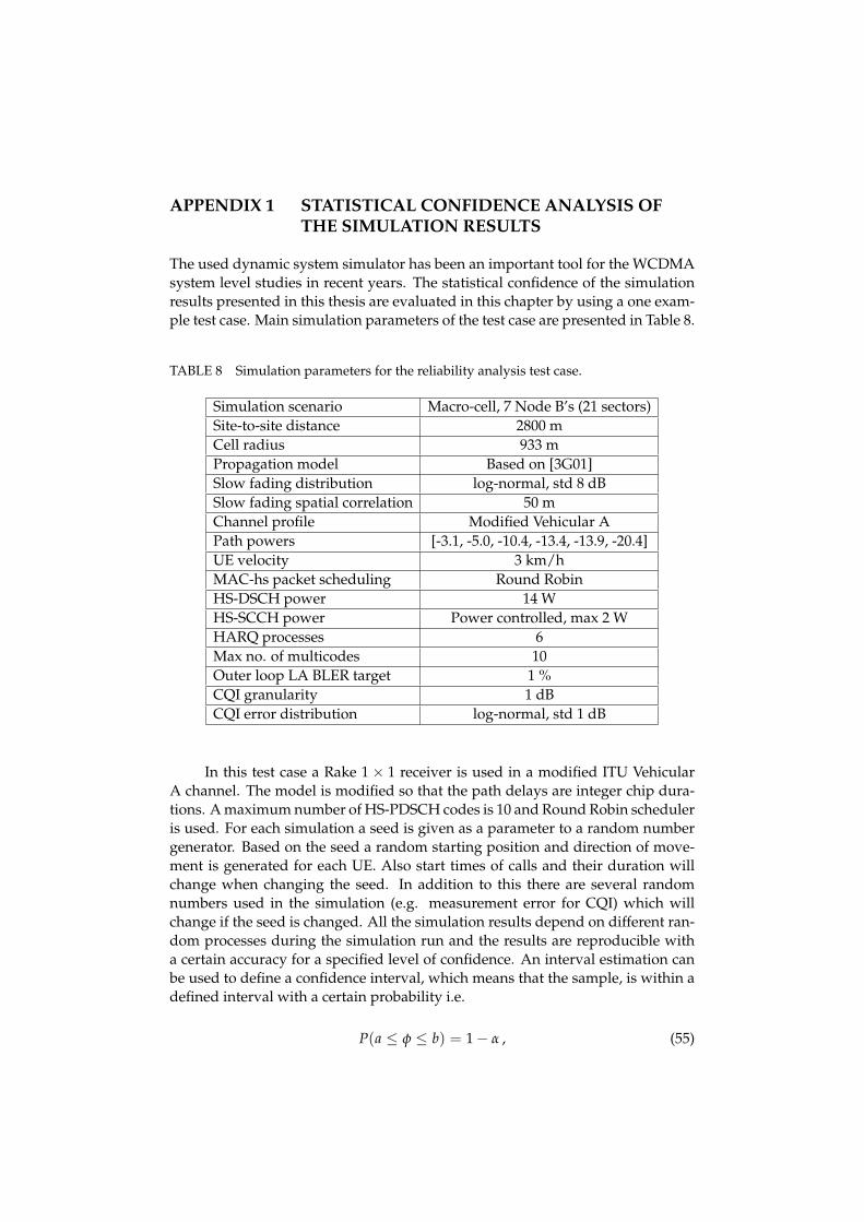
APPENDIX 1 STATISTICAL CONFIDENCE ANALYSIS OFTHE SIMULATION RESULTS
The used dynamic system simulator has been an important tool for the WCDMAsystem level studies in recent years. The statistical confidence of the simulationresults presented in this thesis are evaluated in this chapter by using a one exam-ple test case. Main simulation parameters of the test case are presented in Table 8.
TABLE 8 Simulation parameters for the reliability analysis test case.
Simulation scenario Macro-cell, 7 Node B’s (21 sectors)Site-to-site distance 2800 mCell radius 933 mPropagation model Based on [3G01]Slow fading distribution log-normal, std 8 dBSlow fading spatial correlation 50 mChannel profile Modified Vehicular APath powers [-3.1, -5.0, -10.4, -13.4, -13.9, -20.4]UE velocity 3 km/hMAC-hs packet scheduling Round RobinHS-DSCH power 14 WHS-SCCH power Power controlled, max 2 WHARQ processes 6Max no. of multicodes 10Outer loop LA BLER target 1 %CQI granularity 1 dBCQI error distribution log-normal, std 1 dB
In this test case a Rake 1 × 1 receiver is used in a modified ITU VehicularA channel. The model is modified so that the path delays are integer chip dura-tions. A maximum number of HS-PDSCH codes is 10 and Round Robin scheduleris used. For each simulation a seed is given as a parameter to a random numbergenerator. Based on the seed a random starting position and direction of move-ment is generated for each UE. Also start times of calls and their duration willchange when changing the seed. In addition to this there are several randomnumbers used in the simulation (e.g. measurement error for CQI) which willchange if the seed is changed. All the simulation results depend on different ran-dom processes during the simulation run and the results are reproducible witha certain accuracy for a specified level of confidence. An interval estimation canbe used to define a confidence interval, which means that the sample, is within adefined interval with a certain probability i.e.
P(a ≤ φ ≤ b) = 1 − α , (55)

89
where the interval [a, b] is a (1− α) · 100% confidental interval of φ. A probabilitythat the φ is not within the interval is α. When the number of samples n ≥ 30the standardized normal distribution N(0, 1) can be used to define a confidentalinterval, which is (
x − zα/2 · s√n
,x + zα/2 · s√n
), (56)
where x is the average value, s√n is the critical value taken from the standardized
normal distribution N(0, 1), s is the standard deviation and n is the number ofsamples i.e. the number of simulations.
The confidence interval can be used to evaluate the statistical confidence ofthe simulation results. In the analysis of the simulations ran for this thesis theaverage cell throughput, HS-DSCH SINR and the user bit rate are taken into ac-count. Average cell throughput is the average instantaneous HS-DSCH through-put in a TTI collected from all the sectors in a simulation area during the wholesimulation time. Average HS-DSCH SINR is collected from scheduled mobilesduring the whole simulation time. Average user bit rate is calculated by dividingthe number of transmitted bits during the call divided by the call time. It is calcu-lated at the end of each call. Due to that there are relatively few samples gatheredcompared to cell throughput and HS-DSCH SINR, which are gathered every TTI.Thus, also the confidence interval for user bit rate statistic is higher.
Confidence intervals of 90 %, 95 % and 99 % are presented in Table 9 andconcerning the cell throughputs they are ± 0.21 %, ± 0.32 % and ± 0.38 % re-spectively. The confidence intervals were calculated from the simulation resultsfrom n = 35 simulation runs with different random generator seeds presented inTable 10.
TABLE 9 Statistical confidence intervals.
Variable 90 % 95 % 99 %Cell throughput ± 0.21 % ± 0.32 % ± 0.38 %HS-DSCH SINR ± 0.10 % ± 0.16 % ± 0.19 %User bit rate ± 0.68 % ± 1.03 % ± 1.23 %
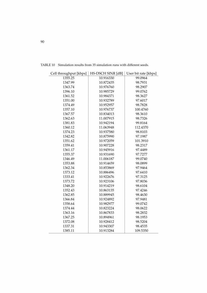
90
TABLE 10 Simulation results from 35 simulation runs with different seeds.
Cell throughput [kbps] HS-DSCH SINR [dB] User bit rate [kbps]1355.25 10.916330 99.09641347.99 10.872435 98.79311363.74 10.976760 98.29071396.10 10.985729 99.07621361.52 10.984371 98.36271351.00 10.932789 97.60171374.49 10.952957 98.78281357.10 10.976737 100.47601367.57 10.834013 98.36101362.63 11.007915 98.73261381.83 10.942194 99.81641360.12 11.063948 112.43701374.23 10.937580 98.81031342.82 10.875990 97.19871351.62 10.972059 101.39101359.41 10.907228 98.23171361.17 10.945916 97.44891355.37 10.931690 97.72771346.49 11.006187 99.07401353.88 10.914659 98.08991362.34 10.853869 97.94641373.12 10.886496 97.64101333.41 10.922676 97.31251373.72 10.923106 97.80361348.20 10.914219 98.61041352.43 10.863135 97.42461362.85 10.889945 98.46301366.84 10.924892 97.94811358.64 10.982977 99.07421374.44 10.823224 98.06221363.16 10.867833 98.28321367.25 10.894961 98.19531372.08 10.928412 98.52041337.31 10.943307 98.45351385.11 10.913284 109.5350

APPENDIX 2 SIMULATION TOOL VERIFICATION
The verification and validation of the simulation results provided in this thesisis done by comparing the results to other HSDPA system simulation results pro-vided by various studies. In [Lov03] system level performance of single and dual-antenna rake and LMMSE equalizer receivers were presented. Although the sim-ulation scenario used in that study differs in many ways from the scenario usedin the simulations of this thesis, the results are very well aligned, as can be seen inTable 11. The presented results are from proportional fair scheduler simulations.
TABLE 11 Cell throughput gain comparison between this thesis and [Lov03].
Receiver Gain [%][Lov03]
Gain [%]Rake 1 × 1 0 % 0 %Rake 1 × 2 44-57 % 44-50 %Equ 1 × 1 25-30 % 24-31 %Equ 1 × 2 88-115 % 89-103 %
Also in [Ram03] simulations similar to those presented in this thesis wereconducted. Single and dual antenna Rake receiver simulations with and with-out transmit diversity were conducted in Vehicular A and Pedestrian A channelswith round robin and proportional fair schedulers with 3 km/h UE velocity. InTable 12 the comparison of the cell throughputs is presented for a Vehicular Achannel.
TABLE 12 Cell throughput and gain comparison between this thesis and [Ram03].
Receiver[Ram03]
RR PF RR PF[kbps] [%] [kbps] [%] [kbps] [%] [kbps] [%]
Rake 1 × 1 1049 0 % 1683 0 % 712 0 % 1079 0 %
Rake 2 × 1,1019 -3 % 1437 -15 % 695 -2 % 918 -15 %
STTDRake 2 × 1,
1528 46 % 2063 23 % 891 25 % 1176 9 %CL1
Rake 1 × 2 2131 103 % 2706 61 % 1206 69 % 1457 35 %
Rake 2 × 2,2378 127 % 2844 69 % 1403 97 % 1552 44 %
CL1
As can be seen in Table 12, the results with 1 × 1 Rake and STTD are nearly

92
the same. The gain of CL Mode 1 and receive diversity schemes the gains and theabsolute throughputs of [Ram03] are lower. The lower throughputs can be ex-plained with the fact that in [Ram03] the amount of power reserved for HSDPAwas 9 watts as it was 14 watts in the simulations of this thesis. The difference be-tween the results of this thesis and [Ram03] is clearly proportional to the achievedthroughput. As the maximum number of multicodes reserved for HSDPA was 7in [Ram03] the highest throughputs in that study might be limited by the MCSdynamics. In simulations presented in this thesis a maximum of 10 multicodeswere allocated, thus higher throughput with equally good signal quality than in[Ram03] could be achieved.


