57
Page 1 Fault Analysis Lecture Note Prepared By Eng. Essam Abdel Halim Mostafa Predictive Maintenance Manager Delta Co. For Electronics E-mail: [email protected]

Page 1
Fault Analysis
Lecture Note
Prepared By
Eng. Essam Abdel Halim Mostafa
Predictive Maintenance Manager
Delta Co. For Electronics
E-mail: [email protected]

Page 2
The main advantage of making vibration measurements on rotating machinery, is the possibility to detect faults, before they make the machine break down, and thereby reduce economical losses, such as damaged equipment and production loss. To this the constant percentage band width spectrum has shown to be the most efficient.
When a fault is detected, vibration analysis can be used to diagnose thefault.
Making diagnosis using vibration analysis requires skill and experience.
Additional measurements of FFT spectra and phase measurements isoften required.
In the following some simple rules for the most common machine faults are drawn up giving the fault type and a characteristic vibration measurements.
The spectra in the examples are all made as drawings, in order to emphasize the typical feature of each fault.
Fault Analysis
UnbalanceMisalignmentPulleys faultsBent shaftShaft crackMechanical loosenessJournal bearing faultsRolling element bearing faultsRotor rubElectrical motor problemsPumps ProblemsGear faults

Page 3
A rotor is not completely balanced when the center of gravity axis does not coincides with the rotational axis as prescribed by construction.
e: Center of gravity displacementr: Radius to unbalance massS: Center of gravityu: Unbalance massm: Rotor massF: Centrifugal force
F
uS
e
r
m
Unbalance
Unbalance Definition
Unbalance:
Specific unbalance or center of gravity eccentricity:
Centrifugal force: mrue
22 ruUF Su
meruUS
The effects of unbalance will be:Displacement of the center of gravityCentrifugal forces created during rotation

Page 4
Unbalance
Please Note: Strong unbalance cause harmonics
Typical UnbalanceSpectrum
Typical UnbalanceSpectrum
-If an unbalance is added to a completely balanced rotor in the same radial plane as the center of gravity, this constitutes a static unbalance. This unbalance causes a parallel displacement of the center of gravity axis from the rotational axis.
Static Unbalance
D
T
E
S
FU
U
T
D
-Equal phase on each bearing
-Mainly radial vibration
E: Center of gravitydisplacement
S: Center of gravityU: Unbalance massD-D: Shaft axisT-T: Center of gravity axis

Page 5
Unbalance
Please Note: Strong unbalance cause harmonics
Typical UnbalanceSpectrum
Typical UnbalanceSpectrum
E: Center of gravitydisplacement
S: Center of gravityU: Unbalance massD-D: Shaft axisT-T: Center of gravity axis
Couple Unbalance
D D
T
TS
FU1
FU2 U1 = U2
- If two equal unbalances are added to a completely balanced rotor at the same radius in two different planes exactly opposite one another, they constitute a couple unbalance. In this case the center of gravity axis is inclined to the rotational axis and intersects it at the center of gravity of the rotor.
- Phase changes 180 ° across bearing-Mainly radial vibration

Page 6
Unbalance
Please Note: Strong unbalance cause harmonics
Typical UnbalanceSpectrum
Typical UnbalanceSpectrum
E: Center of gravitydisplacement
S: Center of gravityU: Unbalance massD-D: Shaft axisT-T: Center of gravity axis
- Phase changes across bearing
- Mainly radial vibration
-A combination of static and couple unbalance existing in most rotors. In this case the center of gravity axis is inclined to the rotational axis and intersects it at a point other than the center of gravity of the rotor.
Quasi-static Unbalance
DDT
TS
FU1
FU2 U1 U2

Page 7
Unbalance
Please Note: Strong unbalance cause harmonics
Typical UnbalanceSpectrum
Typical UnbalanceSpectrum
E: Center of gravitydisplacement
S: Center of gravityU: Unbalance massD-D: Shaft axisT-T: Center of gravity axis
-Mainly radial vibration
Dynamic Unbalance
D D
TTS
FU1
FU2 U1 U2
A combination of static and couple unbalance existing in most rotors. In this case the center of gravity axis is inclined to the rotational axis but does not intersects it.

Page 8
Higher dynamic bearing loading– Speeds up wear and shortens service life time– Makes use of lighter/cheaper
constructions of bearing types impossible– Makes high service speeds impossible/undesirable
Fatigue fracture– Fracture of housings, associated parts and
foundations– Breaking of rotating shaft components– Makes service speeds near resonance frequencies
dangerous
Increased mechanical looseness– Screws, bolts and key couplings loosened by
excessive shaking
Results of Unbalance (1)
Page 9
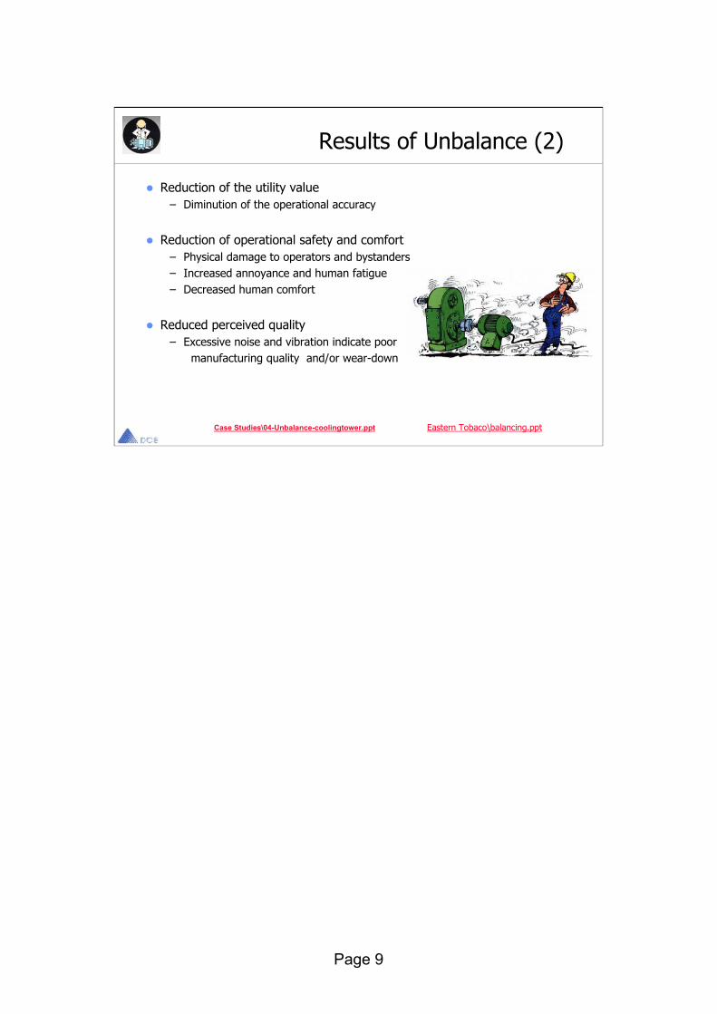
Reduction of the utility value– Diminution of the operational accuracy
Reduction of operational safety and comfort– Physical damage to operators and bystanders– Increased annoyance and human fatigue– Decreased human comfort
Reduced perceived quality– Excessive noise and vibration indicate poor
manufacturing quality and/or wear-down
Eastern Tobaco\balancing.ppt
Results of Unbalance (2)
Case Studies\04-Unbalance-coolingtower.ppt

Page 10
Misalignment is traditionally associated with a 2nd harmonic component, which according to some sources is due to to 2 times the stress reversal during one rotation. More probably the harmonic occurs due to distortion of the ideal sinusoidal vibration signal.
It is quite common that misalignment occurs on the 1st harmonic only in the spectrum. An investigation of the phase relationship across the rotor and across the coupling should therefore always be carried out for distinguishing misalignment from unbalance.
A misaligned rotor tend to wear in. That is after a while the bearing will get deformed after the misalignment. In the spectrum this is seen as the 2nd order component will decrease and the third order will increase as wear develops.
Causes of MisalignmentMisalignment is typically caused by the following conditions:
Inaccurate assembly of components, such as motors, pumps, etc.Relative position of components shifting after assemblyDistortion due to forces exerted by pipingDistortion of flexible supports due to torqueTemperature induced growth of machine structureCoupling face not perpendicular to the shaft axisSoft foot, where the machine shifts when hold down bolts are torqued.
Misalignment
B. Angular misalignment
A. Parallel misalignment
mm/s
1X 2X 3X
10
3.1
1
0.31
1X 2X 3X
mm/s
10
3.1
1
0.31
Axial Vibration approx.. 180 ° phase shiftedAnd in phase in radial direction.1X , 2X or 3 X highest
Radial Vibration approx. 180 ° phase shifted2X often highest peak
Please Note:Misalignment may be appears on 1X component only
Please Note:Misalignment may be appears on 1X component only

Page 11
– Vibration.
– Bearing failure.
– Seal Leakage
Misalignment Results (1)
Seal Manufacturer verifies:50 times longer machine operation through proper shaft alignment
Page 12
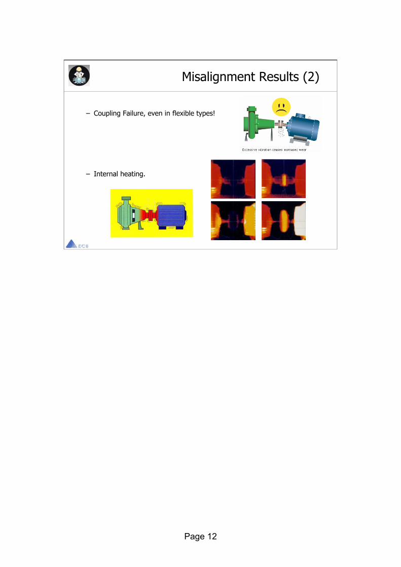
– Coupling Failure, even in flexible types!
– Internal heating.
Misalignment Results (2)
Page 13
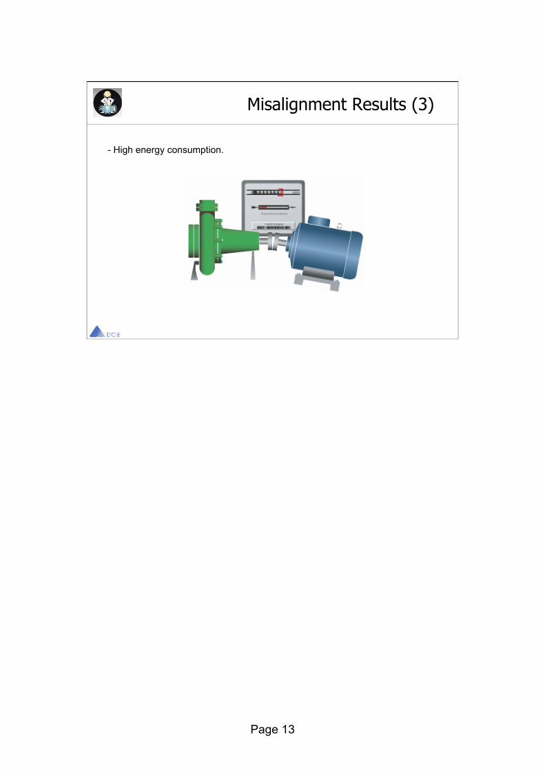
- High energy consumption.
Misalignment Results (3)

Page 14
Page 15
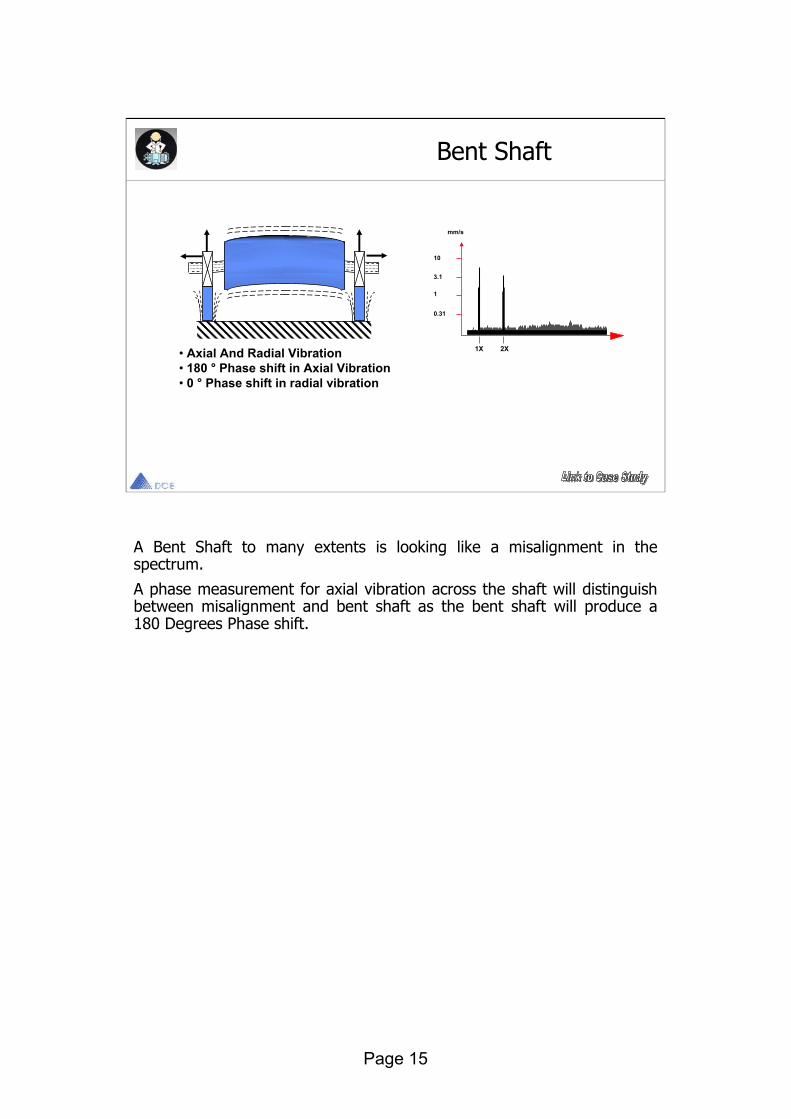
A Bent Shaft to many extents is looking like a misalignment in the spectrum.
A phase measurement for axial vibration across the shaft will distinguish between misalignment and bent shaft as the bent shaft will produce a 180 Degrees Phase shift.
Bent Shaft
• Axial And Radial Vibration• 180 ° Phase shift in Axial Vibration• 0 ° Phase shift in radial vibration
1X 2X
mm/s
10
3.1
1
0.31

Page 16
Belt Drive Problem
Where D = Sheave DiameterL = Belt LengthRPM = Turn speed of sheave D
Where D = Sheave DiameterWhere D = Sheave DiameterL = Belt LengthL = Belt LengthRPM = Turn speed of sheave DRPM = Turn speed of sheave D
Mismatched, Worn, or Stretched BeltsMismatched, Worn, or Stretched BeltsMismatched, worn, or stretched belts, especially Vee belts, will generate vibration at the fundamental belt pass frequency and harmonics of it. Usually the second harmonic is dominant if there are two sheaves in the system. The Fundamental BeltFrequency FBF is given by the following formula. It is always sub-synchronous, meaning it is lower in frequency than 1X.
Fundamental Belt Frequency (FBF) = *D*RPM/L
FBF
2x FBF
10
3.1
1
0.31
Frequency
Vib
rati
on A
mpl
itu
de
Variable Definitions:PS = Pulley rpm (PS1 = Driver Pulley Speed, PS2 = Driven Pulley Speed)PD = Pulley diameter (PD1 = Driver Pulley Dia., PD2 = Driven Pulley Dia)SD = Distance between shaft centersBL = Belt LengthBelt Length = 1.57 x (PD1 + PD2) + 2(SD)

Page 17
Sheave misalignment will generate strong axial 1X components andaxial harmonics of the fundamental belt frequency.
Sheave Misalignment
Belt Drive Problem Cont.
Parallel Angular Both
Page 18
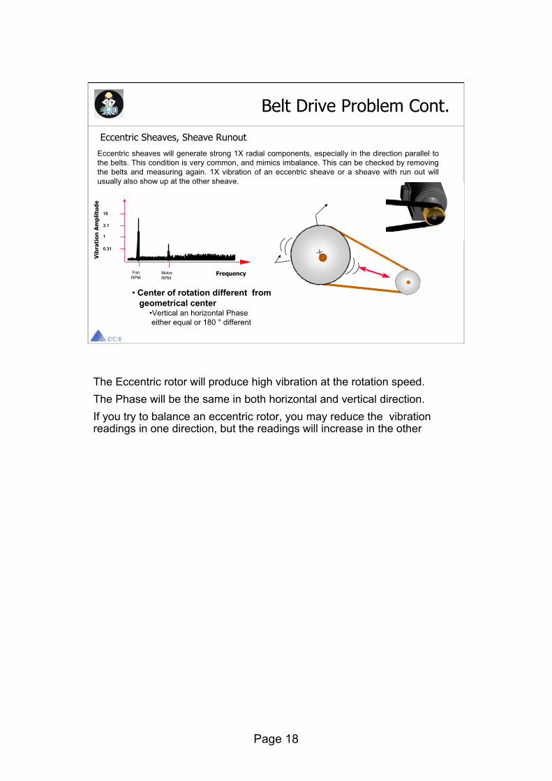
Eccentric sheaves will generate strong 1X radial components, especially in the direction parallel to the belts. This condition is very common, and mimics imbalance. This can be checked by removing the belts and measuring again. 1X vibration of an eccentric sheave or a sheave with run out will usually also show up at the other sheave.
Eccentric Sheaves, Sheave Runout
• Center of rotation different from geometrical center
•Vertical an horizontal Phaseeither equal or 180 ° different
Belt Drive Problem Cont.
FanRPM
MotorRPM
10
3.1
1
0.31
Frequency
Vib
rati
on A
mpl
itu
de
The Eccentric rotor will produce high vibration at the rotation speed. The Phase will be the same in both horizontal and vertical direction.If you try to balance an eccentric rotor, you may reduce the vibration readings in one direction, but the readings will increase in the other
Page 19
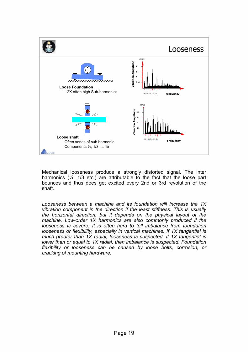
Mechanical looseness produce a strongly distorted signal. The inter harmonics (½, 1/3 etc.) are attributable to the fact that the loose part bounces and thus does get excited every 2nd or 3rd revolution of the shaft.
Looseness between a machine and its foundation will increase the 1X vibration component in the direction if the least stiffness. This is usually the horizontal direction, but it depends on the physical layout of the machine. Low-order 1X harmonics are also commonly produced if the looseness is severe. It is often hard to tell imbalance from foundation looseness or flexibility, especially in vertical machines. If 1X tangential is much greater than 1X radial, looseness is suspected. If 1X tangential is lower than or equal to 1X radial, then imbalance is suspected. Foundation flexibility or looseness can be caused by loose bolts, corrosion, or cracking of mounting hardware.
Loose shaftOften series of sub harmonicComponents ½, 1/3, ... 1/n
Loose Foundation2X often high Sub-harmonics
Loosenessmm/s
.5X 1X 1.5X 2X 3X
10
3.1
1
0.31
Frequency
Vib
rati
on A
mpl
itu
de
mm/s
.5X 1X 1.5X 2X 3X
10
3.1
1
0.31
Frequency
Vib
rati
on A
mpl
itu
de
Page 20
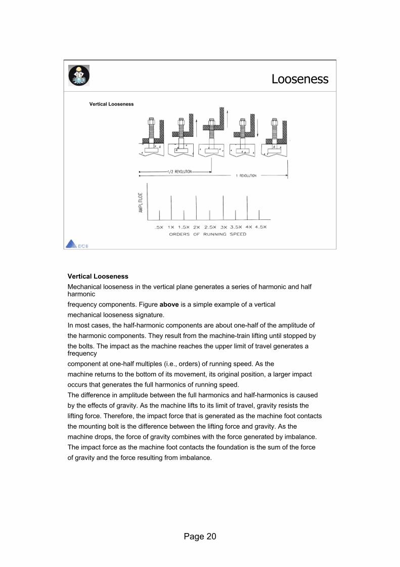
Vertical Looseness
Looseness
Vertical LoosenessMechanical looseness in the vertical plane generates a series of harmonic and half harmonicfrequency components. Figure above is a simple example of a verticalmechanical looseness signature.In most cases, the half-harmonic components are about one-half of the amplitude ofthe harmonic components. They result from the machine-train lifting until stopped bythe bolts. The impact as the machine reaches the upper limit of travel generates a frequencycomponent at one-half multiples (i.e., orders) of running speed. As themachine returns to the bottom of its movement, its original position, a larger impactoccurs that generates the full harmonics of running speed.The difference in amplitude between the full harmonics and half-harmonics is causedby the effects of gravity. As the machine lifts to its limit of travel, gravity resists thelifting force. Therefore, the impact force that is generated as the machine foot contactsthe mounting bolt is the difference between the lifting force and gravity. As themachine drops, the force of gravity combines with the force generated by imbalance.The impact force as the machine foot contacts the foundation is the sum of the forceof gravity and the force resulting from imbalance.

Page 21
Looseness
Horizontal Looseness
The Figure illustrates horizontal mechanical looseness, which is also common to machine-trains. In this example, the machine's support legs flex in the horizontal plane. Unlike the vertical looseness illustrated in previous fig (vertical looseness), gravity is uniform at each leg and there is no increased impact energy as the leg's direction is reversed.Horizontal mechanical looseness generates a combination of first (1x) and second (2x) harmonic vibrations. Since the energy source is the machine’s rotating shaft, the timing of the flex is equal to one complete revolution of the shaft, or 1x . During this single rotation, the mounting legs flex to their maximum deflection on both sides of neutral. The double change in direction as the leg first deflects to one side then the other generates a frequency at two times (2x) the shaft’s rotating speed.

Page 22
The characteristics of Rotor Rub are very similar to mechanics looseness.
Rotor Rub
mm/
.5X 1X 1.5X 2X 2.5X 3X
10
3.1
1
0.31
• Symptoms same as Mechanical Looseness
• Subharmonics ½ ,1/3 etc.• Strong Harmonic pattern
Caused by truncation
Truncated waveform

Page 23
Shaft Cracks have been detected by continuously monitoring of 1st and 2nd harmonics, or by comparing run ups and coast down, where a cracked shaft will change the characteristic curve as it passes through the resonance.Shaft Cracks are often mistaken for the far more common misalignment.
Shaft Crack
Longitudinal Crack
Radial Crack
Shaft Cracks may be detectedby monitoring of
• Amplitude and Phase of 1X first and 2X and second harmonic of RPM.
• Monitoring of Coast downand Run - up characteristicswhen passing throughresonance
Shaft Cracks may be detectedby monitoring of
• Amplitude and Phase of 1X first and 2X and second harmonic of RPM.
• Monitoring of Coast downand Run - up characteristicswhen passing throughresonance
X/Y Position History
1X Run Up
Nyquist Bode
Am
plit
ude
Ph
ase
rpm
rpmRun Up
Page 24
Journal Bearings
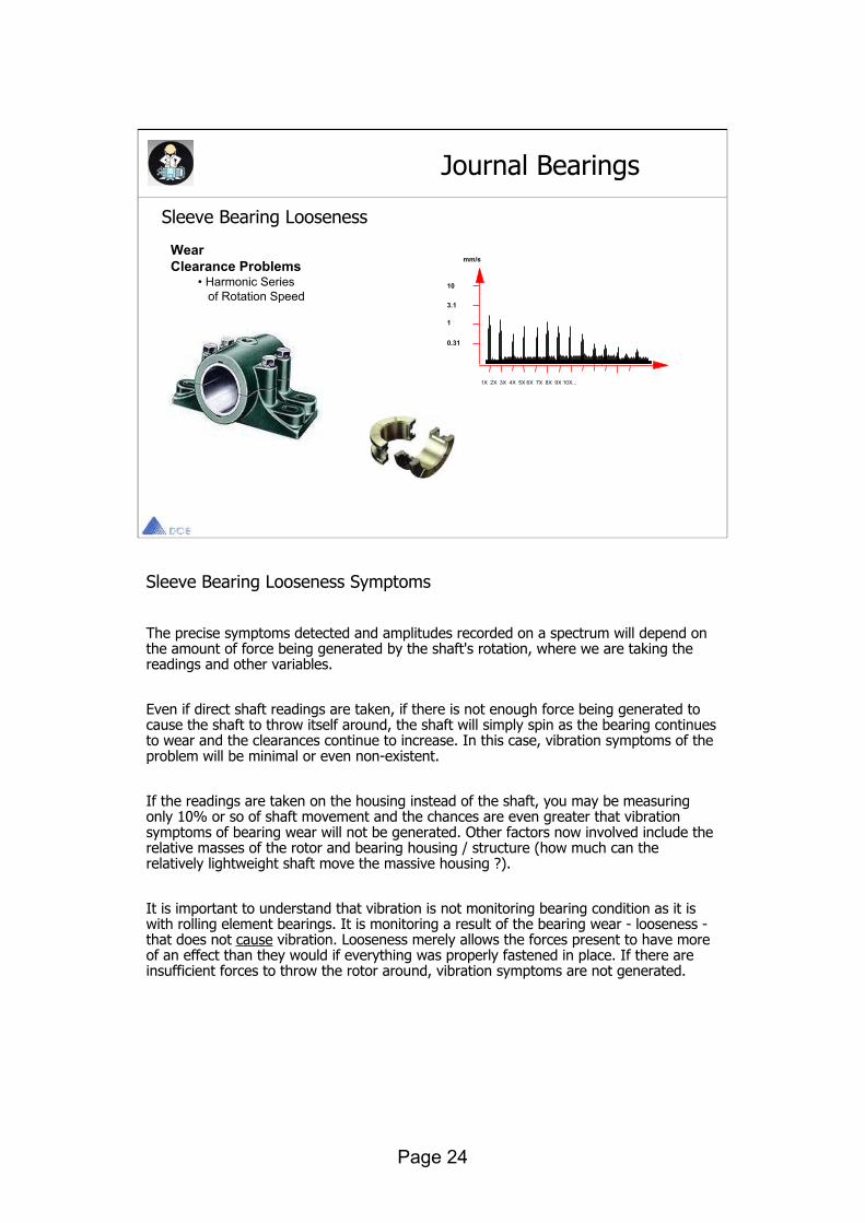
Sleeve Bearing Looseness
WearClearance Problems
• Harmonic Seriesof Rotation Speed
mm/s
1X 2X 3X 4X 5X 6X 7X 8X 9X 10X...
10
3.1
1
0.31
Sleeve Bearing Looseness Symptoms
The precise symptoms detected and amplitudes recorded on a spectrum will depend on the amount of force being generated by the shaft's rotation, where we are taking the readings and other variables.
Even if direct shaft readings are taken, if there is not enough force being generated to cause the shaft to throw itself around, the shaft will simply spin as the bearing continues to wear and the clearances continue to increase. In this case, vibration symptoms of the problem will be minimal or even non-existent.
If the readings are taken on the housing instead of the shaft, you may be measuring only 10% or so of shaft movement and the chances are even greater that vibration symptoms of bearing wear will not be generated. Other factors now involved include the relative masses of the rotor and bearing housing / structure (how much can the relatively lightweight shaft move the massive housing ?).
It is important to understand that vibration is not monitoring bearing condition as it is with rolling element bearings. It is monitoring a result of the bearing wear - looseness -that does not cause vibration. Looseness merely allows the forces present to have more of an effect than they would if everything was properly fastened in place. If there are insufficient forces to throw the rotor around, vibration symptoms are not generated.
Page 25
Journal Bearings
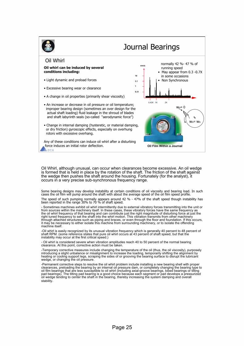
Oil WhirlOil whirl can be induced by several conditions including:
• Light dynamic and preload forces
• Excessive bearing wear or clearance
• A change in oil properties (primarily shear viscosity)
• An increase or decrease in oil pressure or oil temperature; improper bearing design (sometimes an over design for the actual shaft loading) fluid leakage in the shroud of bladesand shaft labyrinth seals (so-called “aerodynamic force”)
• Change in internal damping (hysteretic, or material damping, or dry friction) gyroscopic effects, especially on overhung rotors with excessive overhang.
Any of these conditions can induce oil whirl after a disturbingforce induces an initial rotor deflection. Oil Film Within a Journal
0.43X 1X 2X
10
3.1
1
0.31
mm/s
wo= 0
wo= ws
normally 42 %- 47 % of running speed
• May appear from 0.3 -0.7Xin some occasions
• Non Synchronous
Oil Whirl, although unusual, can occur when clearances become excessive. An oil wedge is formed that is held in place by the rotation of the shaft. The friction of the shaft against the wedge then pushes the shaft around the housing. Fortunately (for the analyst), it occurs in a very precise sub-synchronous frequency range.
Some bearing designs may develop instability at certain conditions of oil viscosity and bearing load. In such cases the oil film will pump around the shaft with about the average speed of the oil film speed profile. The speed of such pumping normally appears around 42 % - 47% of the shaft speed though instability has been reported in the range 30% to 70 % of shaft speed. - Sometimes machines exhibit oil whirl intermittently due to external vibratory forces transmitting into the unit or from sources within the machinery itself. In these cases, these vibratory forces have the same frequency as the oil whirl frequency of that bearing and can contribute just the right magnitude of disturbing force at just the right tuned frequency to set the shaft into the whirl motion. This vibration transmits from other machinery through attached structures such as piping and braces, or even through the floor and foundation. If this occurs, it may be necessary to either isolate this machine from surrounding machinery, or to isolate the offending machine itself. -Oil whirl is easily recognized by its unusual vibration frequency which is generally 40 percent to 48 percent of shaft RPM. (some reference states that pure oil whirl occurs at 43 percent of shaft speed, but that the instability may occur at the first critical speed.)- Oil whirl is considered severe when vibration amplitudes reach 40 to 50 percent of the normal bearing clearance. At this point, corrective action must be taken. -Temporary corrective measures include changing the temperature of the oil (thus, the oil viscosity), purposely introducing a slight unbalance or misalignment to increase the loading, temporarily shifting the alignment by heating or cooling support legs, scraping the sides of or grooving the bearing surface to disrupt the lubricant wedge, or changing the oil pressure. -Permanent corrective steps to resolve the oil whirl problem include installing a new bearing shell with proper clearances, preloading the bearing by an internal oil pressure dam, or completely changing the bearing type to oil film bearings that are less susceptible to oil whirl (including axial-groove bearings, lobed bearings or tilting pad bearings). The tilting pad bearing is a good choice because each segment or pad develops a pressurized oil wedge tending to center the shaft in the bearing, thereby increasing the system damping and overall stability.

Page 26
Oil Whip
Oil Film Within a Journal
0.43X 1X 2X
10
3.1
1
0.31
mm/s
Oil Whip Symptoms
Oil whirl is present (bearing clearances are excessive). Problem develops when rotor is running at 2.1-2.4x critical speed (at this speed, the frequency of the rotor's 1st critical is between 0.42-0.48xRPM - the oil whirl range). High vibration develops at frequency of rotor's critical speed. This occurs when the vibration due to the oil whirl condition acts to excite the resonant frequency of the rotor. · High vibration remains at frequency of 1st critical even as rotor speed continues to increase.
Journal Bearings
Page 27
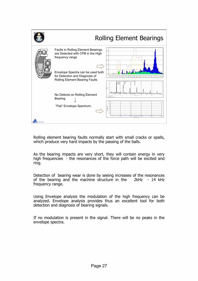
Rolling element bearing faults normally start with small cracks or spalls, which produce very hard impacts by the passing of the balls.
As the bearing impacts are very short, they will contain energy in very high frequencies - the resonances of the force path will be excited and ring.
Detection of bearing wear is done by seeing increases of the resonances of the bearing and the machine structure in the 2kHz - 14 kHz frequency range.
Using Envelope analysis the modulation of the high frequency can be analyzed. Envelope analysis provides thus an excellent tool for both detection and diagnosis of bearing signals.
If no modulation is present in the signal. There will be no peaks in the envelope spectra.
Rolling Element Bearings
Faults in Rolling Element Bearingsare Detected with CPB in the High frequency range
Envelope Spectra can be used both for Detection and Diagnosis of Rolling Element Bearing Faults
No Defects on Rolling Element Bearing
“Flat” Envelope Spectrum.
Page 28
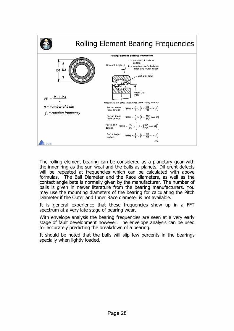
The rolling element bearing can be considered as a planetary gear with the inner ring as the sun weal and the balls as planets. Different defects will be repeated at frequencies which can be calculated with above formulas. The Ball Diameter and the Race diameters, as well as the contact angle beta is normally given by the manufacturer. The number of balls is given in newer literature from the bearing manufacturers. You may use the mounting diameters of the bearing for calculating the Pitch Diameter if the Outer and Inner Race diameter is not available.
It is general experience that these frequencies show up in a FFTspectrum at a very late stage of bearing wear.
With envelope analysis the bearing frequencies are seen at a very early stage of fault development however. The envelope analysis can be used for accurately predicting the breakdown of a bearing.
It should be noted that the balls will slip few percents in the bearings specially when lightly loaded.
Rolling Element Bearing Frequencies
D1 D2
PD D D1 22
n = number of balls
f r = rotation frequency
Page 29
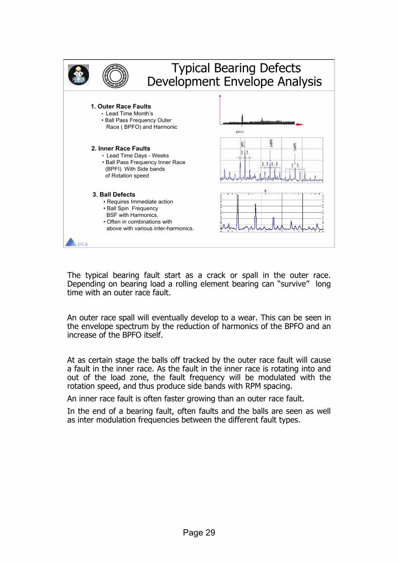
The typical bearing fault start as a crack or spall in the outer race. Depending on bearing load a rolling element bearing can “survive” long time with an outer race fault.
An outer race spall will eventually develop to a wear. This can be seen in the envelope spectrum by the reduction of harmonics of the BPFO and an increase of the BPFO itself.
At as certain stage the balls off tracked by the outer race fault will cause a fault in the inner race. As the fault in the inner race is rotating into and out of the load zone, the fault frequency will be modulated with the rotation speed, and thus produce side bands with RPM spacing.
An inner race fault is often faster growing than an outer race fault.
In the end of a bearing fault, often faults and the balls are seen as well as inter modulation frequencies between the different fault types.
Typical Bearing Defects Development Envelope Analysis
3. Ball Defects • Requires Immediate action • Ball Spin Frequency
BSF with Harmonics.• Often in combinations with
above with various inter-harmonics.
1. Outer Race Faults• Lead Time Month’s• Ball Pass Frequency Outer
Race ( BPFO) and Harmonic
2. Inner Race Faults• Lead Time Days - Weeks• Ball Pass Frequency Inner Race
(BPFI) With Side bands of Rotation speed
BPFO
RPM
BPFI
BSF

Page 30
The earliest detection of bearing fault is done by placing the envelope filter on a resonance of the bearing. By doing so however, one miss the opportunity of classifying the defect depth, by the height of the peaks in the envelope spectrum.
Also one misses the opportunity of being able to analyze above defects in the envelope spectra.
For getting the best information about modulations of random noise produced by a rolling element bearing, it is recommended to place the envelope filter in the high frequency at a place where signal is available, but not amplified by resonances. (There should be maximum 10dB variation across the envelope filter range).
Bearing Mounting Defects Analyzed With Envelope Analysis
RPM
2*RPM
2*BPFO
Lubrication Defect
Rotor Misalignment Rotor Unbalance
Radial Tension of Bearing
Misalignment ofouter Race (Cocked)
Slip of Race inthe Mounting Seat
2*RPM
1*RPM
2*BPFO
Harmonicsof RPM
Increase ofBackgroundlevel
RPM

Page 31
AC Motor Induction Motor Problems
Electrically Generated Vibrations
The supply of AC power to a motor generates mechanical vibration. Since AC power is supplied as a sinusoid, each pole of the motor is energized twice once with a "+" peak and once with a "-"peak during each cycle.
This means that the most common vibration frequency that is generatedis NOT line frequency it is 2x line frequency ( 2 x 50 Hz= 100 Hz)

Page 32
There are two spectra necessary to detecting electrically-related problems. Each example that follows is taken on one or the other.
•High frequency (200 x RPM). •High resolution (12kcpm Fmax w/ 1600 lines is usually sufficient).
There are also certain terms and frequencies which must be defined:
FLine = Electrical line frequency - normally 50 Hz (3000 rpm) or 60 Hz (3600 rpm).
2 x FLine = Torque Pulse Frequency. This is a common frequency found on a high resolution spectrum.
P = # of poles on the motor. The number of poles is how the speed of the motor is controlled. The greater the number of poles, the slower the motor runs. The number of poles is always an even number (2, 4, 6, etc.).
AC Motor Induction Motor Problems

Page 33
AC Induction Motor Problems: Air gap Variation, Stator Weakness & Winding Shorts
Air Gap Variation, Winding Shorts, Stator Weakness Symptoms:
High amplitudes at 2 x FLine.
Recommended Actions:
Check for soft foot and repair. Check alignment and repair. Perform winding tests to assess insulation integrity of the windings. Live with it or buy a new motor.
The Stator- consists of the windings and the metal of the motor housing itself (i.e. the 'iron', or 'core'). The symptom we will see here is related to variation in the air gap between the windings and the rotor. That air gap is not perfectly even all the way around. Since the strength of a magnetic field - which causes the rotation of the rotor - is proportional to the gap (the smaller the gap, the stronger the force), variation in the gap produces vibration at (2 x FLine). The greater the variation, the higher the amplitude. The air gap can also be affected, however, by mechanical problems such as soft foot (which stresses & distorts the housing), stator looseness / weakness (allowing it to be influenced to a greater degree by those magnetic forces) and winding shorts (which cause localized heating and thermal distortion). The only one of the previous problems that is easily tested for and fixed is soft foot.

Page 34
AC Induction Motor Problems:Eccentric Rotor
Eccentric Rotor Symptoms
-High amplitudes at 2 x FLine. -Possible sidebands around 2x line frequency and/or 1x rpm.
Recommended Actions:-Check for soft foot and repair. -Check alignment and repair. -On-line current analysis to assess condition and determine severity. -Live with it or buy a new motor.
NOTE: It is important to realize that vibration at 2 x FLine is a normallyoccurring vibration. The effect on the bearings is no greater or less than the same amplitude due to unbalance. Do not over-react.
NOTE: Do not confuse the presence of a running speed harmonic with a pole pass frequency sideband. By definition, a running speed harmonic will always be separated from 2 x FLine by pole pass frequency.

Page 35
AC Induction Motor Problems: Phasing Problems
One Possible Spectrum Caused By A Problem WithA Short In One Of The Phases Or Feeder Cables
Single Phasing Symptoms:symptom).only(this can be the FLineHigh amplitudes at 2 x
Sidebands around 2 x FLine at 1/3 FLine (1/3 line frequency).
Recommended Actions:This may occur with a sudden, dramatic increase in amplitudes. In that case, a short should be suspected and testing should be performed. Inspect connections at junction box on motor. Surge test unit from motor control center.
in the leads, splices or windings.anywhereThis will detect a problem If a problem is found, the splices at the motor should be broken and the leads and windings tested separately to isolate the problem. If nothing found in windings, on-line current analysis should be performed on the motor.
Another Possible Spectrum Caused By A Problem With A Short In One Of The Phases Or Feeder Cables
The main problem caused by phasing shorts is impeding the free flow of current to the motor. This can cause problems ranging from danger to personnel to heat-related damage to catastrophic motor failure.

Page 36
AC Induction Motor Problems:Broken / Cracked Rotor Bars
Broken Cracked Rotor Bar Symptoms:FPole sidebands surrounding running speed harmonics.Advanced problems will exhibit a 'humming' or 'pulsing' sound and feel. Significant is the number of and size of the sidebands. They increase as the unit Deteriorates. Amplitude at 1x rpm is relatively unimportant - it will fluctuate greatly as thehot spots being generated cause the rotor to bow unpredictably.
It is a result of the problem - not a cause.
Recommended Actions:On-line current analysis to determine severity. Limit starts since they are easily the single, most destructive thing you can do to a motor.

Page 37
AC Induction Motor Problems: Loose Rotor Bars
Loose Rotor Bar Symptoms:High amplitude at a very high frequency (WSPF, but we don't know what it is) accompanied by sidebands at 2 x FLine.
–or 2.5 mm/sec ipsbelow 0.1 -This symptom is not unusual and at low amplitudes often means little more than an imperfection in the machine.In fact, it usually has more to do with a potential winding problem than rotor bar looseness.Vibration at 2 x WSPF and even 3 x WSPF w/ sidebands at 2 x FLine. These are much more unusual and indicate a much more potentially severe problem. Symptoms identical to the next problem - looseness in the windings(make sure both are understood before recommending any action for either problem).
Recommended Actions:On-line current analysis to determine severity. If a healthy rotor is found, it is more likely a potential winding problem.Winding testing in addition to rotor testing will provide for a comprehensive eletrcial PdM program.
Loose rotor bars- Extremely unusual and never found in cast rotors. As a loose rotor bar passes a winding slot, the magnetic force causes it to momentarily lift and then drop. The frequency, then, is the number of windings slots x RPM (Winding Slot Pass Frequency or WSPF). The number of winding slots will be between about 25 and 100. The bad news is that you will not know the number of winding slots and it is very difficult to find out. The good news is that the vibration is accompanied by a precise sideband - 2 x FLine.

Page 38
AC Induction Motor Problems: Loose in Winding Slots, Iron, End Turns And/Or Connections
Envelope Plot Showing 2xLine Peak And Harmonics. This Indicates Impacts Occurring At 2xLine Frequency.
Velocity FFT Showing Pattern Of Peaks Separated By 2xLine Frequency (Sidebands)In High Frequency Range (30-90xRPM).
Looseness In The Windings Symptoms:High amplitude at a very high frequency (RBPF, but we don't know what it is) accompanied by sidebands at 2 x FLine. This is not unusual and often means little. In fact, it often has more to do with a potential winding problem than rotor bar looseness
and harmonics. FLinespectra at 2 x envelopingAmplitude peaks on the
Recommended Actions:Surge testing to check insulation integrity and test for any wire to wire, turn to turn and phase to phase shorts as well as the integrity of the ground wall insulation.
Looseness in the winding slots- are detectable with vibration analysis but cannot be trended towards failure since the problem does not worsen (vibration-wise) prior to winding failure. The problem causes wear of the insluation on the windings and eventually a ground short (catastrophic failure). Only winding testers (surge testing) can trend this problem and assess the severity. It is commonly found and should not be over-reacted to. The symptoms are very similar to loose rotor bars on the velocity / acceleration spectra. Additionally, however, there will be high amplitude peaks on your enveloping spectra (e.g. gSE spectrum) at 2 x FLine and harmonics. Each time a rotor bar passes the loose winding, it lifts and then drops back. The vibration frequency, therefore, is the number of rotor bars x RPM (rotor bar pass frequency = RBPF). Like WSPF, it will be surrounded by 2 x FLine sidebands. Like the number of winding slots, we won't know the number of rotor bars but it's not important - the pattern of peaks separated by 2 x FLine is the clue we need.

Page 39
AC Variable Frequency Drives
Variable Frequency Drives - VFD's are AC motors that give the operator the speed control that a DC Drive normally provides at a small fraction of the cost and difficulty in maintenance and troubleshooting. It operates exactly as an AC induction motor does with all of the same electrically generated frequencies.That's the good news.
The bad news is that a VFD is the vibration analyst's worst nightmare.For example, the vibration frequencies detectable with both AC induction motors
and DC motors are constant - only a couple vary at all and they are part of a easily recognizable pattern. With a VFD, the speed is controlled by modifying the frequency of the power supply. In other words, a motor normally running at 3550 rpm can be slowed down to, say, 1775 rpm (1/2) by reducing line frequency from 60 Hz to 30 Hz. In all likelihood, however, you will not know the exact frequency being supplied to the motor and that is the problem
Page 40
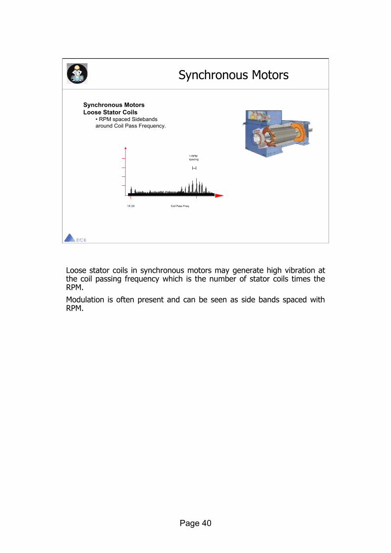
Loose stator coils in synchronous motors may generate high vibration at the coil passing frequency which is the number of stator coils times the RPM.
Modulation is often present and can be seen as side bands spaced with RPM.
Synchronous Motors
Synchronous MotorsLoose Stator Coils
• RPM spaced Sidebandsaround Coil Pass Frequency.
1X 2X Coil Pass Freq.
1 RPMspacing
Page 41
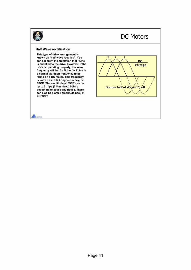
This type of drive arrangement is known as "half-wave rectified". You can see from the animation that FLineis supplied to the drive. However, if the drive is operating properly, the seen frequency will be 3x FLine. 3x FLine is a normal vibration frequency to be found on a DC motor. This frequency is known as SCR firing frequency, or FSCR. The amplitude at FSCR can be up to 0.1 ips (2.5 mm/sec) before beginning to cause any notice. There can also be a small amplitude peak at 2x FSCR.
DC Motors
Half Wave rectification
1 32
DCVoltage
Bottom half of Wave Cut off

Page 42
FSCR on a full-wave rectified drive is, of course, 6x Line Frequency. You can see how a full-wave rectified drive gives better control and a more constant voltage than a half-wave rectified drive does.
Full Wave rectification
1 32 DCVoltage
4 5 6
Bottom half of Wave Cut off
DC Motors
Page 43
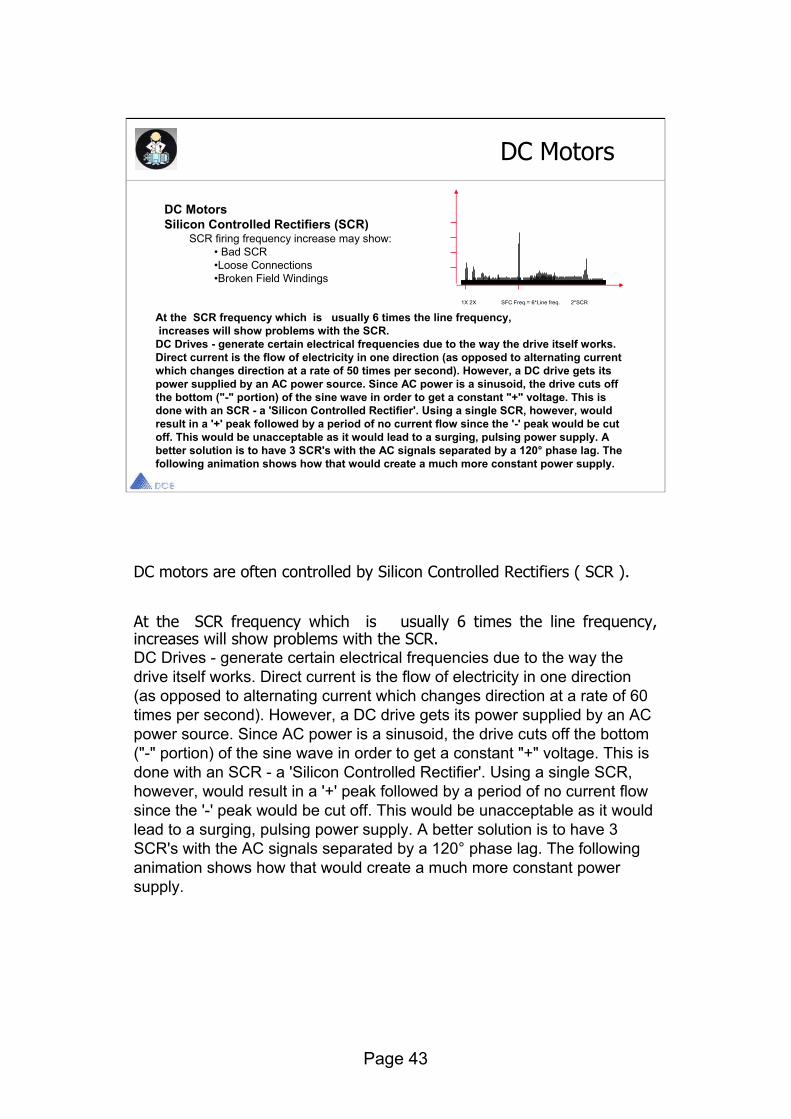
DC motors are often controlled by Silicon Controlled Rectifiers ( SCR ).
At the SCR frequency which is usually 6 times the line frequency, increases will show problems with the SCR. DC Drives - generate certain electrical frequencies due to the way the drive itself works. Direct current is the flow of electricity in one direction (as opposed to alternating current which changes direction at a rate of 60 times per second). However, a DC drive gets its power supplied by an AC power source. Since AC power is a sinusoid, the drive cuts off the bottom ("-" portion) of the sine wave in order to get a constant "+" voltage. This is done with an SCR - a 'Silicon Controlled Rectifier'. Using a single SCR, however, would result in a '+' peak followed by a period of no current flow since the '-' peak would be cut off. This would be unacceptable as it would lead to a surging, pulsing power supply. A better solution is to have 3 SCR's with the AC signals separated by a 120° phase lag. The following animation shows how that would create a much more constant powersupply.
DC Motors
DC MotorsSilicon Controlled Rectifiers (SCR)
SCR firing frequency increase may show:• Bad SCR•Loose Connections•Broken Field Windings
1X 2X SFC Freq.= 6*Line freq. 2*SCR
At the SCR frequency which is usually 6 times the line frequency, increases will show problems with the SCR.
DC Drives - generate certain electrical frequencies due to the way the drive itself works. Direct current is the flow of electricity in one direction (as opposed to alternating current which changes direction at a rate of 50 times per second). However, a DC drive gets its power supplied by an AC power source. Since AC power is a sinusoid, the drive cuts off the bottom ("-" portion) of the sine wave in order to get a constant "+" voltage. This is done with an SCR - a 'Silicon Controlled Rectifier'. Using a single SCR, however, would result in a '+' peak followed by a period of no current flow since the '-' peak would be cut off. This would be unacceptable as it would lead to a surging, pulsing power supply. A better solution is to have 3 SCR's with the AC signals separated by a 120° phase lag. The following animation shows how that would create a much more constant power supply.
Page 44
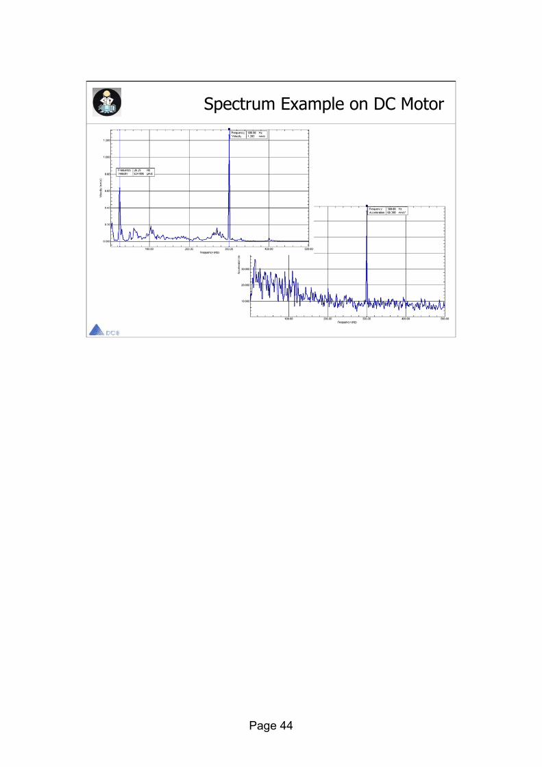
Spectrum Example on DC Motor

Page 45
Cavitation begins as the formation of vapor bubbles at the impeller eye due to low pressure.
The bubbles form at the position of lowest pressure at the pump inlet which is just prior to the fluid being acted upon by the impellervanes and then rapidly compressed.
The compression of the vapor bubbles produces a small shock wave that impacts the impeller surface and pits away at the metal creating over time large eroded areas and subsequent failure.
The sound of cavitation is very characteristic and resembles the sound of gravel in a concrete mixer.
Centrifugal Pumps Problems

Page 46
The faster a fluid travels by an object the lower the pressure will be, this phenomenon is well known as Bernoulli's law, and it is the reason that aero planes can fly and turbo machines are working.
The lower the pressure, the lower the boiling temperature of water.
In some instances the water of a pump may start boiling locally as a result of the local fluid speed will decrease local dynamic pressure and hence decreased the boiling point below the fluid temperature.
When the local pressure increases again the small bubbles formed in the boiling process collapses very rapidly. The rapid collapse causes shock pulses which may be strong enough to break apart fragments of metal on the location it occurs - cavitation wear.
The collapsing bubbles also induce shock waves which are transferred through the structure. Since the pulses are very short, they have a very high frequency content, and they will excite resonances throughout the spectrum range.
CavitationCavitation is caused by the collapse of small bubbles that occurs during local boiling at certain condition of the fluid (low dynamic pressure) The Collapses are short in time and thus wide in Frequency.
-The resonances are exited throughout the spectrum
-Specially high Frequencies are exited
- In Envelope Spectra an increase of the backgroundlevel with no distinct lines are seen.
Pumps Problems
Constant Percentage Bandwidth Spectrum Envelope Spectrum
Centrifugal PumpsThe following spectrum, containing broadband high-frequency noise,indicates cavitation in a centrifugalpump due to low inlet pressure.

Page 47
Pumps Problems Cont.
Gear Pumps
Gear pumps are commonly used for pumping lube oil, and they almost always have a strong vibrationcomponent at the tooth mesh frequency, which is the number of teeth on the gear times the RPM. This component will be highly dependent on the output pressure of the pump. If the tooth mesh frequency changes significantly, such as the sudden appearance of harmonics or sidebands in the vibration spectrum, it could indicate a cracked or otherwise damaged tooth.
Typical Gear Pump Spectrum
1X
GearMeshing
Frequency
Frequency
Vib
rati
on A
mpl
itu
de

Page 48
Pumps Problems Cont.
Screw Pumps
The screw type pump can generate a multitude of frequency components in the vibration spectrum. Thread (loop) wear or damage will usually produce strong harmonics of the thread rate, which is the number of threads (loop) times the RPM.
1XLoop
Meshing Frequency
Frequency
Vib
rati
on A
mpl
itu
de

Page 49
Fan Problems
Fan
Spee
d
BladePassing
Frequency
Frequency
Vib
rati
on A
mpl
itu
de
FansA phenomena similar to gear mesh frequency is Van passing frequency on fluid-handling machines.The source of Van Passing frequency is a pressure fluctuation as a Van Passes a discontinuity within its chamberThe Van Passing Frequency is always the product of the rotational speed times the number of Vanes.
Mot
orSp
eed
Fan are the cause of more field vibration problems than any other category of machines. Motors easily outnumber every other kind of machine and are a significant source of vibration on their own, but fans require more attention to keep running. The reasons are their function and their construction.

Page 50
1XScrew
Meshing Frequency
Frequency
Vib
rati
on A
mpl
itu
de
Compressor Problems
Screw Compressor The screw type compressor can generate a
multitude of frequency components in the vibration spectrum. Thread (loop) wear or damage will usually produce strong harmonics of the thread rate, which is the number of threads (loop) times the RPM.

Page 51
Gear box spectra contains a range of frequencies of the different tooth mesh and its harmonics.
The tooth mesh frequency itself, is generally dependent of gearbox load, whereas gear box wear can be diagnosed as an increase of the 2nd and 3rd harmonic.
Side bands around the tooth mesh frequency and its harmonics, are quite common and contains information about gearbox faults.
As a general rule a distributed faults such as runout and gear misalignment will produce side bands which have high amplitudes close around the fault, whereas distributed faults produce side bands which are spread more widely.
Cepstrum analysis produce an excellent tool for analyzing the energy in each side band family.
With signal enhancement analysis you may collect the vibration spectrum from a single shaft inside a gear box.
Use of Order analysis will eliminate smearing the many components together due to small speed variations.
Gears
Gear Boxes Produce Complex Spectra
Cepstrum Analysis and Time Domainaveraging greatly simplifies the job ofthe analysis in assessment of Gear Box faults.
Gear Box Spectrum• Faults produce Side Band families
around tooth mesh frequency (TMF)
and harmonics TMF.
Gear Box Spectrum• Faults produce Side Band families
around tooth mesh frequency (TMF)
and harmonics TMF.
Gear Box Cepstrum• The Energy of each Side Band
Family (fault) is easily assessed.
Gear Box Cepstrum• The Energy of each Side Band
Family (fault) is easily assessed.
TMF 2*TMF

Page 52
Gear Normal Spectrum
Normal spectrum shows 1X and 2X and gear mesh frequency GMFGMF commonly will have sidebands of running speedAll peaks are of low amplitude and no natural frequencies are present

Page 53
Gear teeth Wear
Wear is indicated by excitation of natural frequencies along with sidebands of the bad gear running speedSidebands are a better wear indicator than the GMFGMF may not change in amplitude when wear occurs

Page 54
Gear Eccentricity and Backlash
Fairly high amplitude sidebands around GMF suggest eccentricity, backlash or non parallel shaftsThe problem gear will modulate the sidebandsIncorrect backlash normally excites gear natural frequency
Page 55
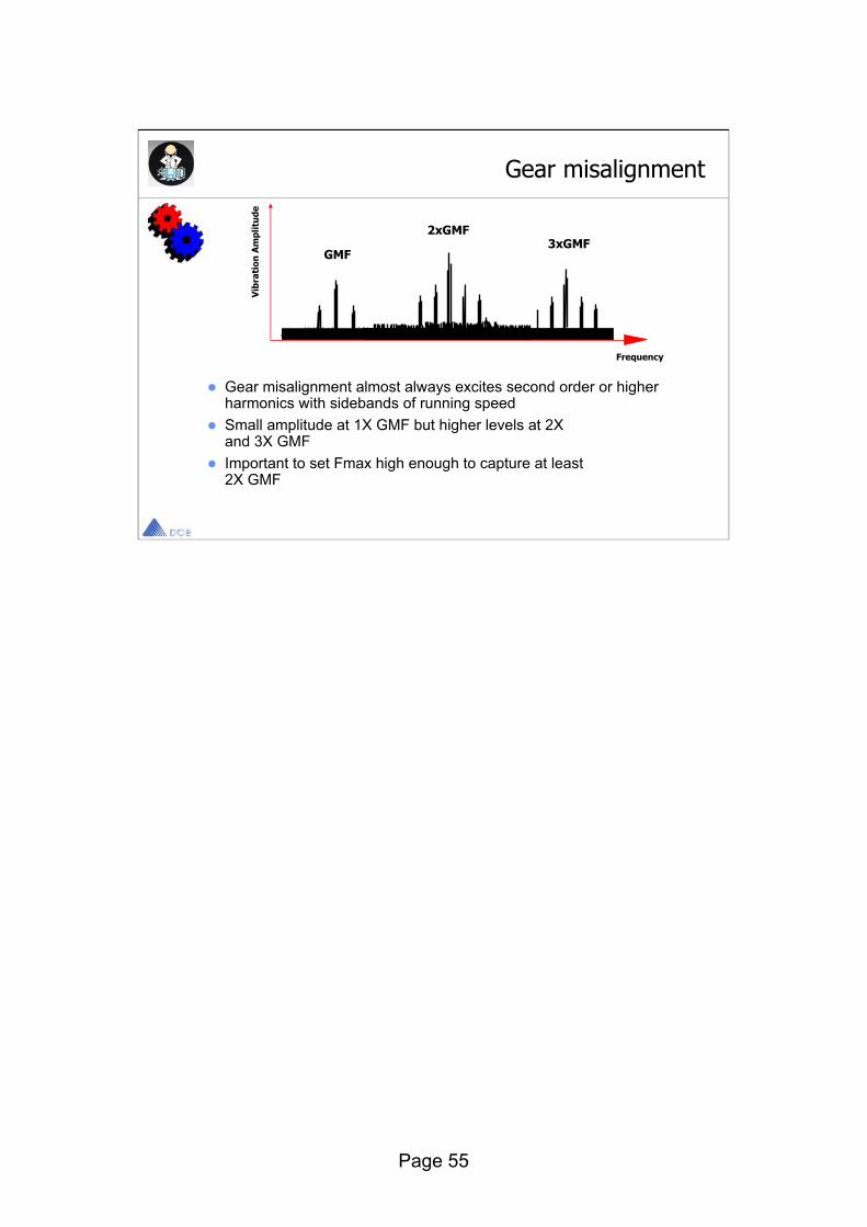
Gear misalignment
Gear misalignment almost always excites second order or higher harmonics with sidebands of running speedSmall amplitude at 1X GMF but higher levels at 2Xand 3X GMFImportant to set Fmax high enough to capture at least2X GMF
GMF
2xGMF3xGMF
Frequency
Vib
rati
on A
mpl
itu
de

Page 56
Cracked or broken tooth
A cracked or broken tooth will generate a high amplitude at 1X RPM of the gearIt will excite the gear natural frequency which will be side banded by the running speed fundamentalTime interval between impacts will be the reciprocal of the 1X RPM
1XGMF
Frequency
Vib
rati
on A
mpl
itu
de

Page 57
End


