Foundation I must create a system, or be enslav’d by another Man’s; I will not reason and compare: my business is to create. --- William Blake Problem: building a network Acknowledgement: this lecture is partially based on the slides of Dr. Larry Peterson, Dr. James Kurose, and Dr. Keith Ross Hongwei Zhang http://www.cs.wayne.edu/~hzhang
Transcript
Foundation
I must create a system, or be enslav’d by another Man’s; I will not reason
and compare: my business is to create.--- William Blake
Problem: building a network
Acknowledgement: this lecture is partially based on the slides of Dr. Larry Peterson, Dr. James Kurose, and Dr. Keith Ross
Hongwei Zhang
http://www.cs.wayne.edu/~hzhang
Outline
� Requirements
� Connectivity
� Cost-effective resource sharing
� Support for common services (Inter-Process Communication)
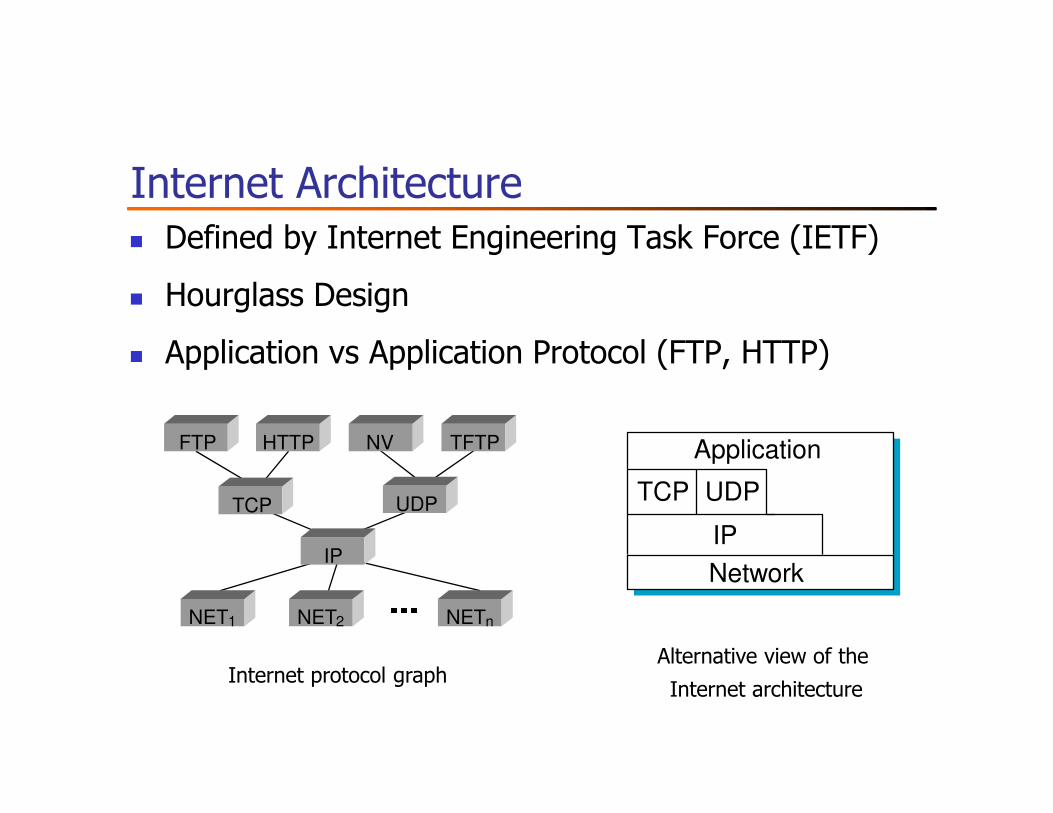
� Network Architecture
� Implementation Issues
� Performance Metrics
� Discussion
Outline
� Requirements
� Connectivity
� Cost-effective resource sharing
� Support for common services (inter-Process Communication)
� Network Architecture
� Implementation Issues
� Performance Metrics
� Discussion
Building Blocks
� Nodes: PC, special-purpose hardware…
� hosts� switches
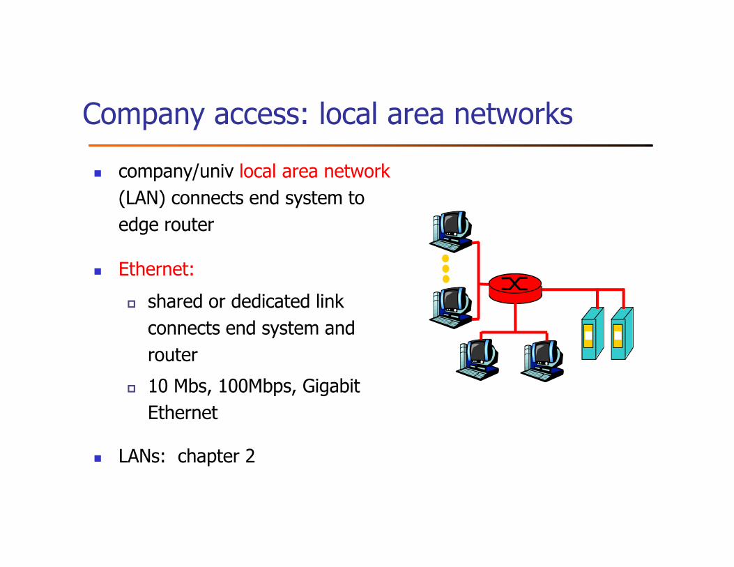
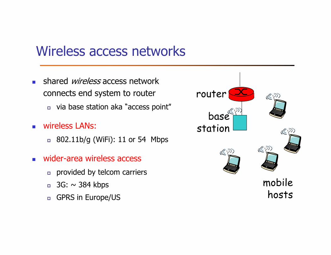
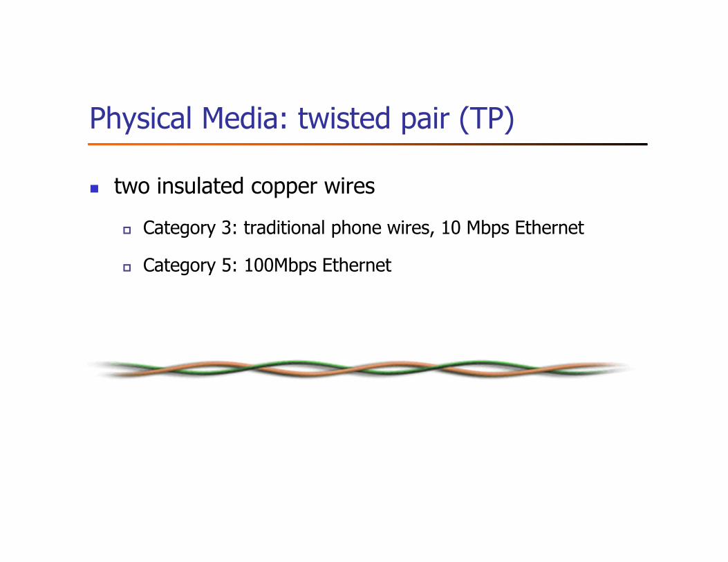
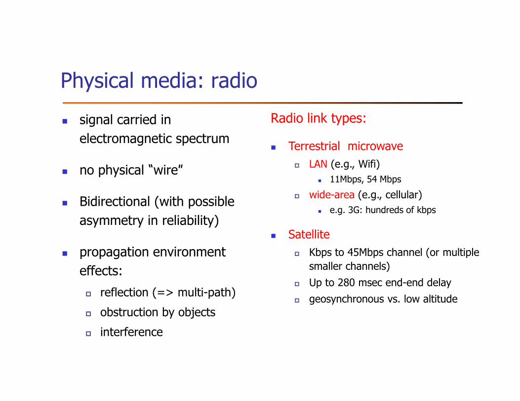
� Links: coax cable, optical fiber…
� point-to-point
� multiple access ■■■(a)
(b)
Switched Networks
� two or more nodes connected by a link, or
� two or more networks connected by a node
� A network can be defined recursively as ...
Addressing and Routing
� Address: byte-string that identifies a node
� usually unique
� Routing: process of forwarding messages to the
destination node based on its address
� Types of addresses
� unicast: node-specific
� broadcast: all nodes on the network
� multicast: some subset of nodes on the network
Outline
� Requirements
� Connectivity
� Cost-effective resource sharing
� Support for common services (inter-Process Communication)
� Network Architecture
� Implementation Issues
� Performance Metrics
� Discussion
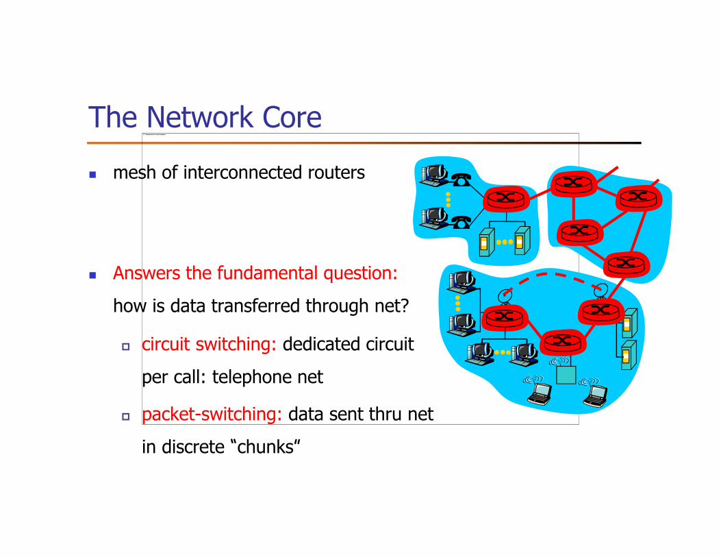
Switching strategies
� Circuit switching: carry bit streams
� original telephone network
� Packet switching: store-and-forward messages
� Internet
Circuit Switching
End-end resources reserved
for “call”
� link bandwidth, switch capacity
� dedicated resources: no sharing
� circuit-like (guaranteed)
performance
� call setup required
Circuit Switching: piece-wise resource allocation
Network resources (e.g., bandwidth) divided into “pieces”
� Pieces allocated to calls
� Resource piece idle if not used by owning call (no sharing)
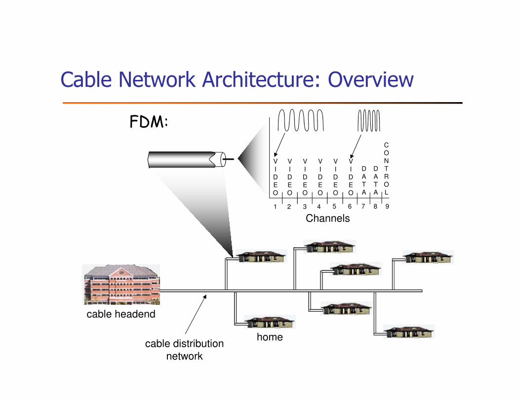
� Dividing link bandwidth into “pieces”
� frequency division
� time division
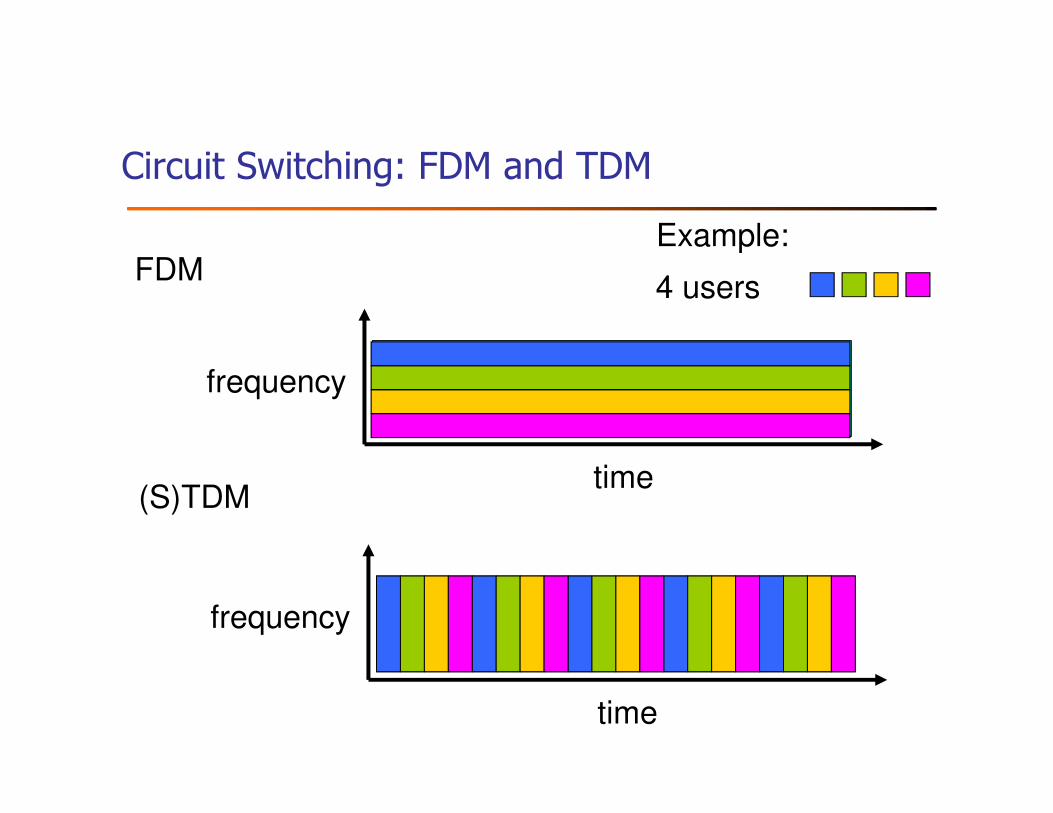
Circuit Switching: FDM and TDM
FDM
frequency
time(S)TDM
frequency
time
4 users
Example:
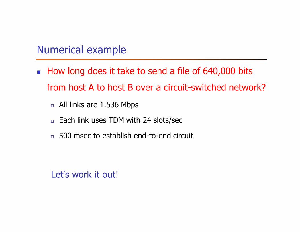
Numerical example
� How long does it take to send a file of 640,000 bits
from host A to host B over a circuit-switched network?
� All links are 1.536 Mbps
� Each link uses TDM with 24 slots/sec
� 500 msec to establish end-to-end circuit
Let’s work it out!
Packet Switching
each end-end data stream divided into packets
� user A, B packets share network resources
� each packet uses full link bandwidth
� resources used as needed
� store and forward: packets
move one hop at a time
� Node receives complete packet
before forwarding
resource contention:
� aggregate resource demand
can exceed amount available
� congestion: packets queue,
wait for link use
Bandwidth division into “pieces”
Dedicated allocation
Resource reservation
Packet Switching: Statistical Multiplexing
Sequence of A & B packets does not have fixed pattern, shared on demand �
statistical multiplexing.
TDM (as in circuit switching): each host gets same slot in revolving TDM frame.
A
B
C100 Mb/sEthernet
1.5 Mb/s
D E
statistical multiplexing
queue of packetswaiting for output
link
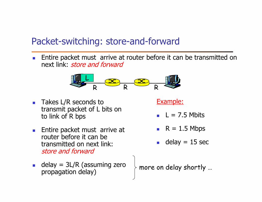
Packet-switching: store-and-forward
� Takes L/R seconds to transmit packet of L bits on to link of R bps
� Entire packet must arrive at router before it can be transmitted on next link: store and forward
� delay = 3L/R (assuming zero propagation delay)
Example:
� L = 7.5 Mbits
� R = 1.5 Mbps
� delay = 15 sec
R R R
L
more on delay shortly …
� Entire packet must arrive at router before it can be transmitted on next link: store and forward
Packet switching vs. circuit switching
Packet switching allows more users to use network!
� 1 Mb/s link
� each user:
� 100 kb/s when “active”
� active 10% of time
� circuit-switching:
� 10 users
� packet switching:
� with 35 users, probability of
> 10 active less than .0004
N users
1 Mbps link
Q: how did we get value 0.0004?
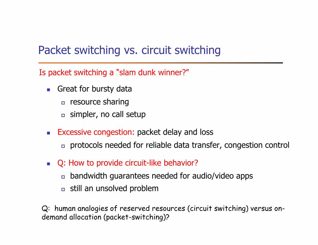
Packet switching vs. circuit switching
� Great for bursty data
� resource sharing
� simpler, no call setup
� Excessive congestion: packet delay and loss
� protocols needed for reliable data transfer, congestion control
� Q: How to provide circuit-like behavior?
� bandwidth guarantees needed for audio/video apps
� still an unsolved problem
Is packet switching a “slam dunk winner?”
Q: human analogies of reserved resources (circuit switching) versus on-demand allocation (packet-switching)?
S: 354 Enter mail, end with "." on a line by itself
C: Do you like ketchup?
C: How about pickles?
C: .
S: 250 Message accepted for delivery
C: QUIT
S: 221 hamburger.edu closing connection
Try SMTP interaction for yourself:
� telnet servername 25
� E.g., telnet www.yahoo.com 25
� see 220 reply from server
� enter HELO, MAIL FROM, RCPT TO, DATA, QUIT commands
above lets you send email without using email client (reader)
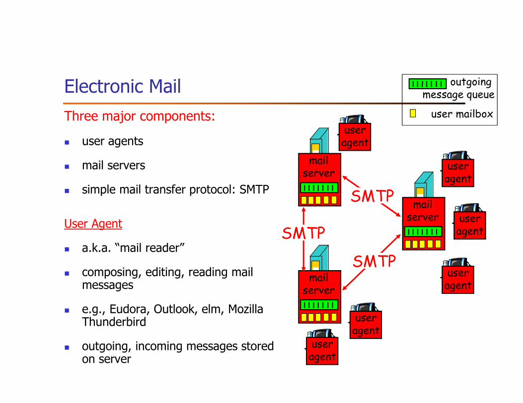
Mail access protocols
� SMTP: delivery/storage to receiver’s server
� Mail access protocol: retrieval from server
� POP: Post Office Protocol [RFC 1939]
� authorization (agent <-->server) and download
� IMAP: Internet Mail Access Protocol [RFC 1730]
� more features (more complex)
� manipulation of stored msgs on server
� HTTP: gmail, Hotmail, Yahoo! Mail, etc.
This image cannot currently be displayed.This image cannot currently be displayed.
useragent
sender’s mail server
useragent
SMTP SMTP accessprotocol
receiver’s mail server
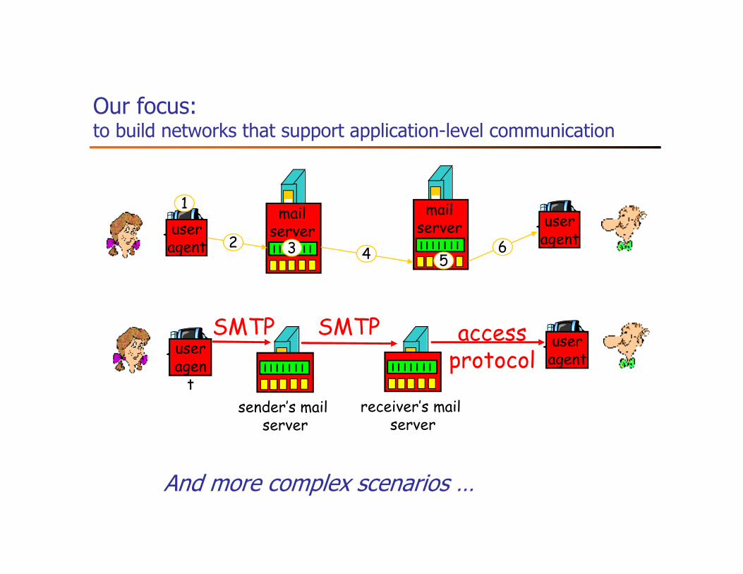
Our focus: to build networks that support application-level communication
useragent
sender’s mail server
useragen
t
SMTP SMTP accessprotocol
receiver’s mail server
useragent
mailserver
mailserver user
agent
1
2 3 4 56
And more complex scenarios …
Assignment - Chapter 1
� Exercise#0:
� Exercises 3, 5, 13, and 26
� Hint: 1) focus on the precise definition of bandwidth and delay; 2) for Ex. 28: image consists of
pixels, with each pixel represented by certain # of bits (e.g., 8)
� Exercise 10
� Hint: identify scenarios where STDM and FDM work well and do not work well respectively
� Exercises 36 and 37
� for both exercises (i.e., ping and traceroute), use command “script” to record the screen
printout and submit it
� May use www.cs.wayne.edu and www.wayne.edu, if you cannot ping/traceroute
www.cs.princeton.edu and www.cisco.com.
� TinyExam#0
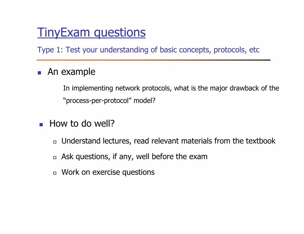
TinyExam questions
Type 1: Test your understanding of basic concepts, protocols, etc
� An example
In implementing network protocols, what is the major drawback of the
“process-per-protocol” model?
� How to do well?
� Understand lectures, read relevant materials from the textbook
� Ask questions, if any, well before the exam
� Work on exercise questions
TinyExam questions
Type 2: Problem solving
� An exampleCalculate the total time required to transfer a 2000-KB file in the following cases, assuming a RTT of 100ms, a packet size of 1KB data, and an initial 2×RTT of “handshaking” before data is sent:
(a) The bandwidth is 1.5Mbps, and data packets can be sent continuously.
(b) The bandwidth is 1.5Mbps, but after we finish sending each data packet we must wait for one RTT before sending the next.
� How to do well
� Work on exercise questions
� Understand the fundamentals of relevant networking concepts, protocols, techniques, etc