1 3.4 Basic Propagation Mechanisms & Transmission Impairments (1) Reflection: propagating wave impinges on object with size >> • examples include ground, buildings, walls (2) Diffraction: transmission path obstructed by objects with edges • 2 nd ry waves are present throughout space (even behind object) • gives rise to bending around obstacle (NLOS transmission path) ttering propagating wave impinges on object with si er of obstacles per unit volume is large (dense) ples include rough surfaces, foliage, street signs, lamp posts
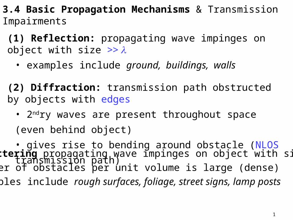
(1) Reflection: propagating wave impinges on object with size >> • examples include ground, buildings, walls
(2) Diffraction: transmission path obstructed by objects with edges
• 2ndry waves are present throughout space (even behind object)
• gives rise to bending around obstacle (NLOS transmission path)
(3) Scattering propagating wave impinges on object with size < • number of obstacles per unit volume is large (dense)• examples include rough surfaces, foliage, street signs, lamp posts
2
Models are used to predict received power or path loss (reciprocal)based on refraction, reflection, scattering
• Large Scale Models
• Fading Models
at high frequencies diffraction & reflections depend on
• geometry of objects
• EM wave’s, amplitude, phase, & polarization at point of intersection
3
3.5 Reflection: EM wave in 1st medium impinges on 2nd medium • part of the wave is transmitted• part of the wave is reflected
(1) plane-wave incident on a perfect dielectric (non-conductor)
• part of energy is transmitted (refracted) into 2nd medium
• part of energy is transmitted (reflected) back into 1st medium
• assumes no loss of energy from absorption (not practically)
(2) plane-wave incident on a perfect conductor
• all energy is reflected back into the medium
• assumes no loss of energy from absorption (not practically)
4
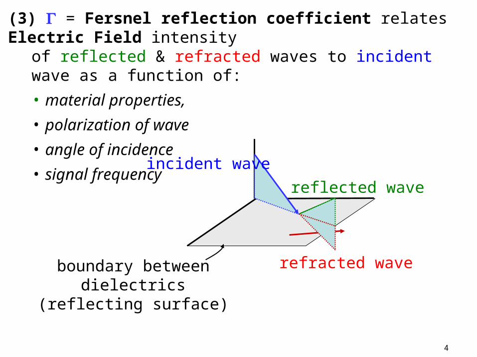
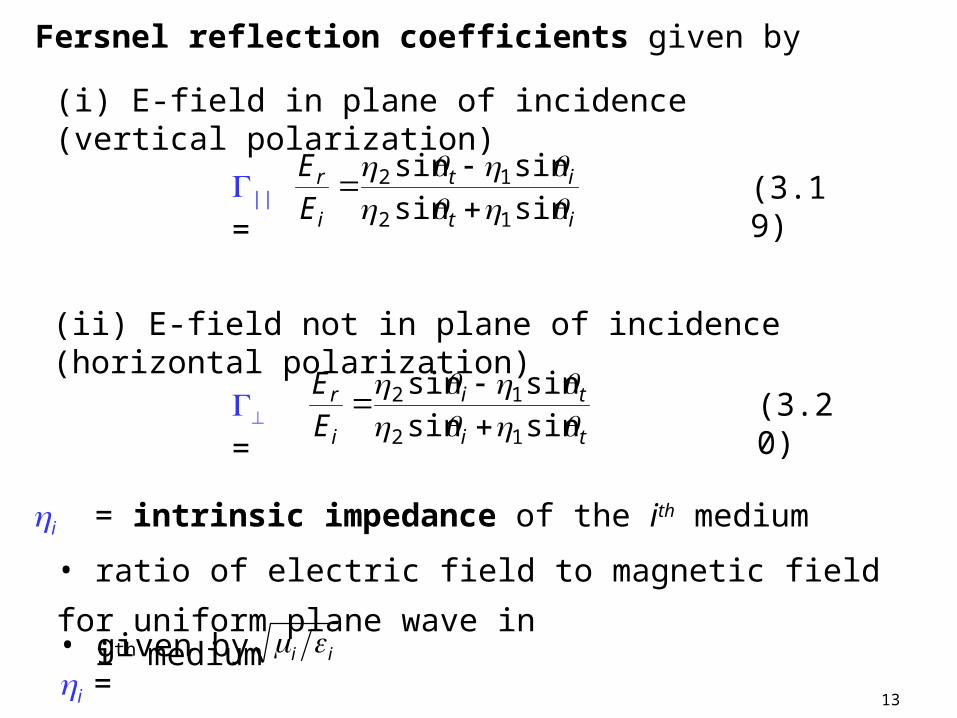
(3) = Fersnel reflection coefficient relates Electric Field intensity of reflected & refracted waves to incident wave as a function of:
• material properties,
• polarization of wave
• angle of incidence
• signal frequency
boundary between dielectrics (reflecting surface)
reflected wave
refracted wave
incident wave
5
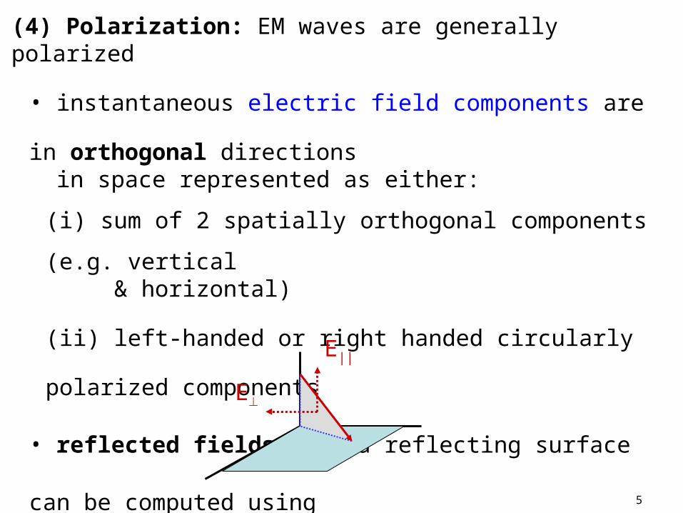
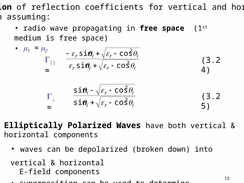
(4) Polarization: EM waves are generally polarized
• instantaneous electric field components are in orthogonal
directions in space represented as either:
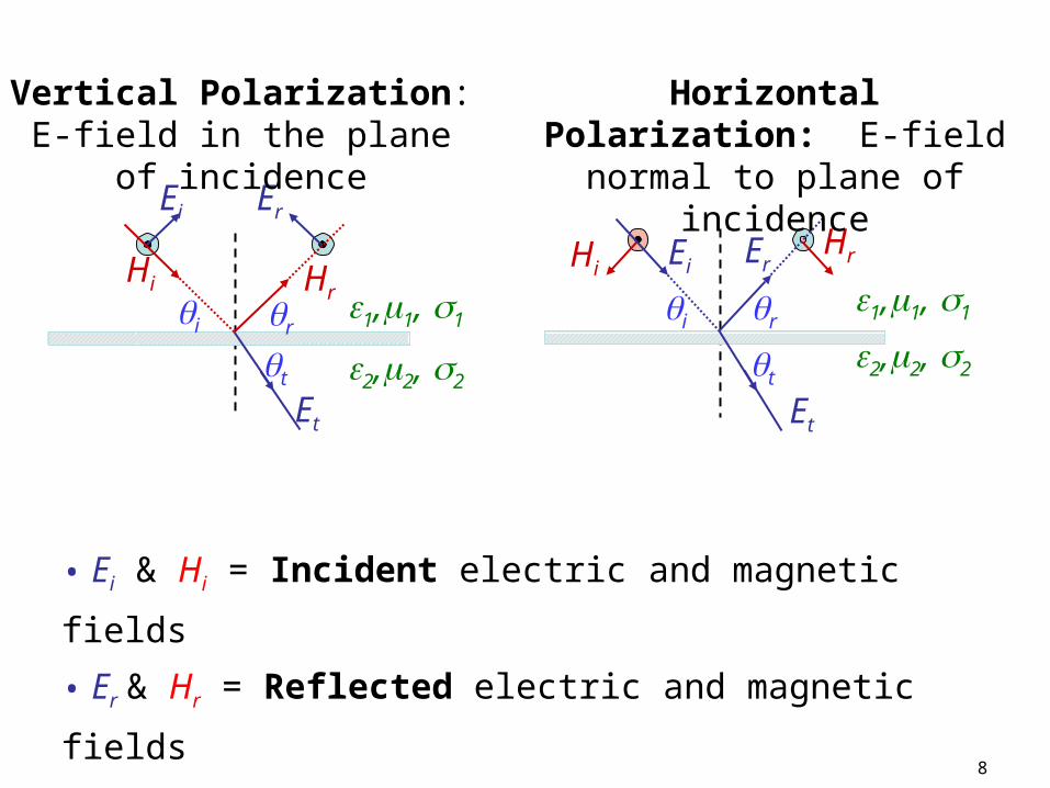
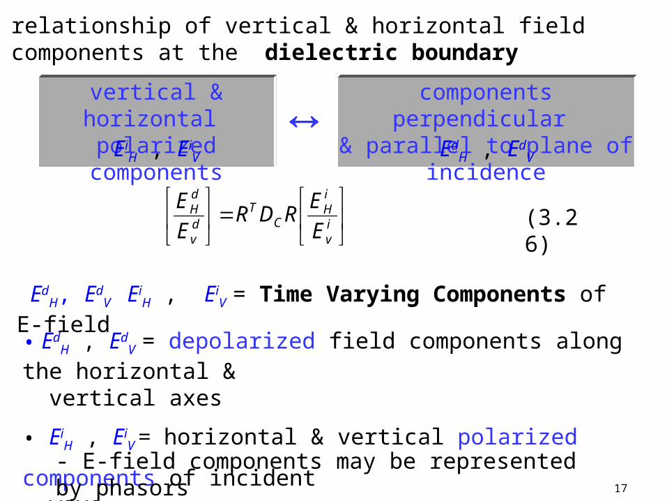
(i) sum of 2 spatially orthogonal components (e.g. vertical & horizontal)
(ii) left-handed or right handed circularly polarized components
• reflected fields from a reflecting surface can be computed using superposition for any arbitrary polarizationE||
E
6
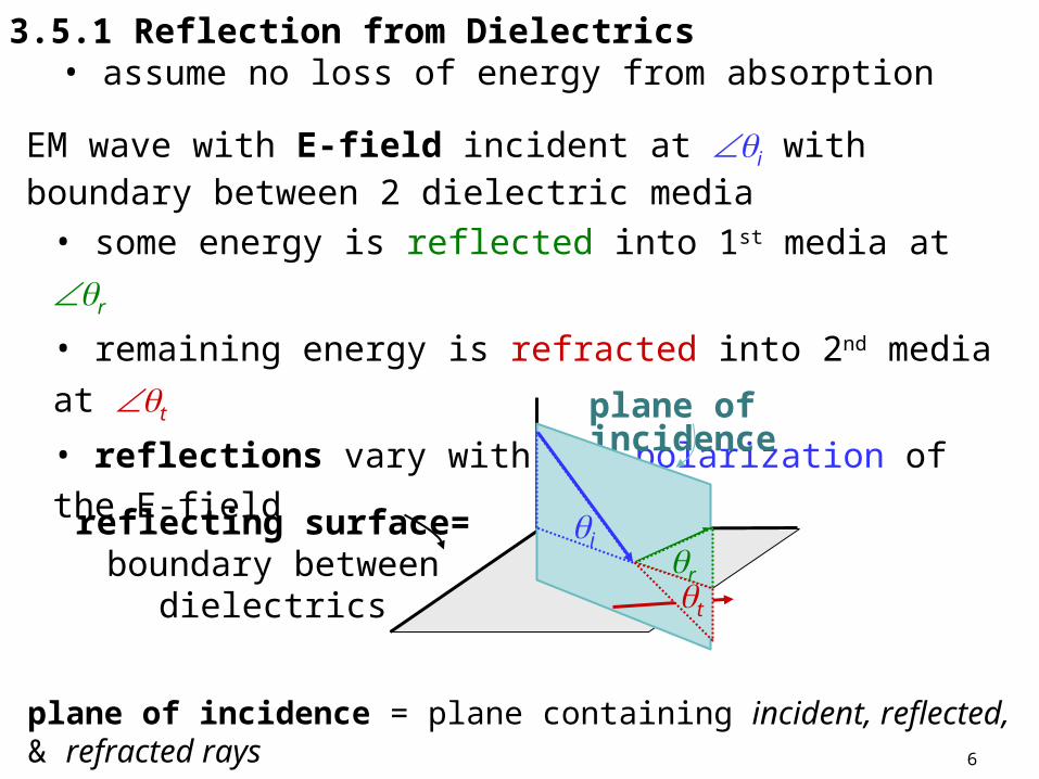
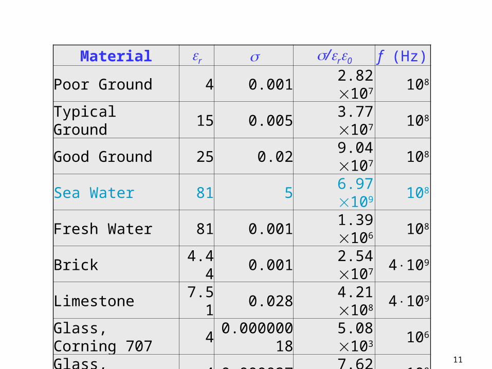
3.5.1 Reflection from Dielectrics • assume no loss of energy from absorption
EM wave with E-field incident at i with boundary between 2 dielectric media
• some energy is reflected into 1st media at r
• remaining energy is refracted into 2nd media at t
• reflections vary with the polarization of the E-field
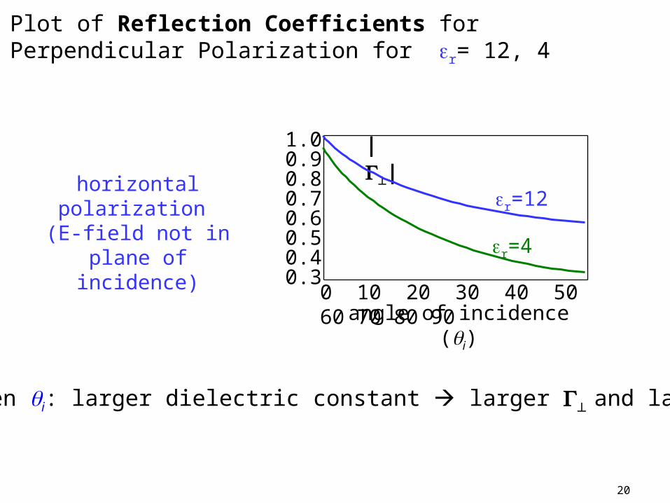
for given i: larger dielectric constant larger and larger Er
Plot of Reflection Coefficients for Perpendicular Polarization for r= 12, 4
21
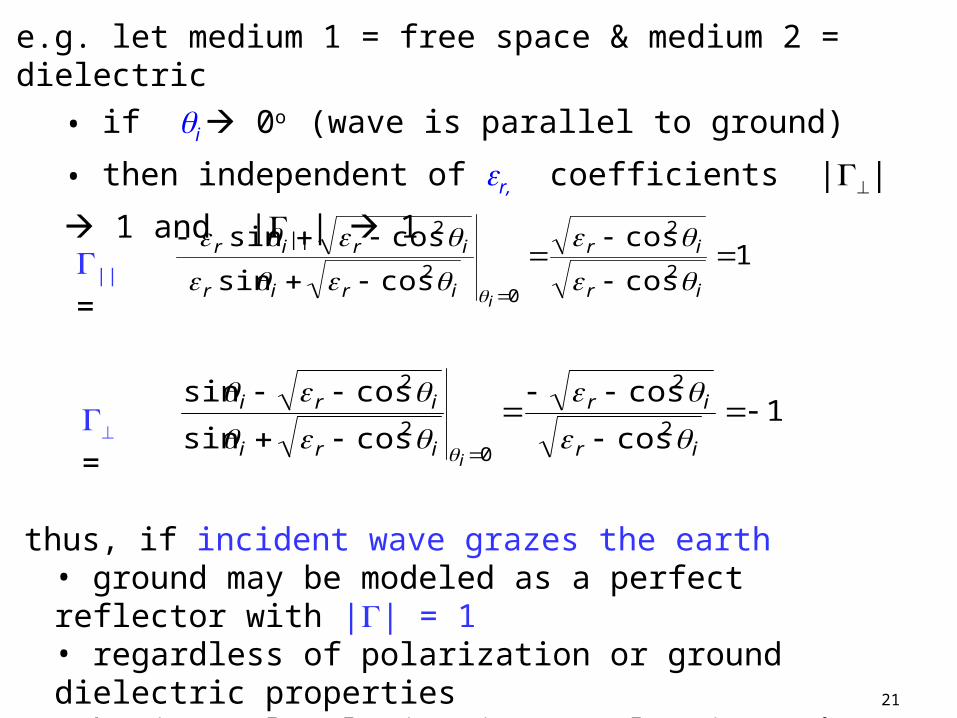
e.g. let medium 1 = free space & medium 2 = dielectric
• if i 0o (wave is parallel to ground)
• then independent of r, coefficients || 1 and |||| 1
|| = 1cos
cos
cossin
cossin2
2
02
2
ir
ir
irir
irir
i
= 1cos
cos
cossin
cossin2
2
02
2
ir
ir
iri
iri
i
thus, if incident wave grazes the earth• ground may be modeled as a perfect reflector with || = 1• regardless of polarization or ground dielectric properties• horizontal polarization results in 180 phase shift
22
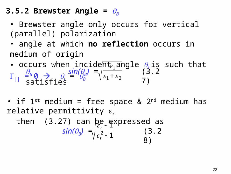
3.5.2 Brewster Angle = B
• Brewster angle only occurs for vertical (parallel) polarization • angle at which no reflection occurs in medium of origin• occurs when incident angle i is such that || = 0 i = B
• if 1st medium = free space & 2nd medium has relative permittivity r then (3.27) can be expressed as
1
12
r
r
sin(B) = (3.28)
sin(B) = 21
1
(3.27
)B satisfies
23
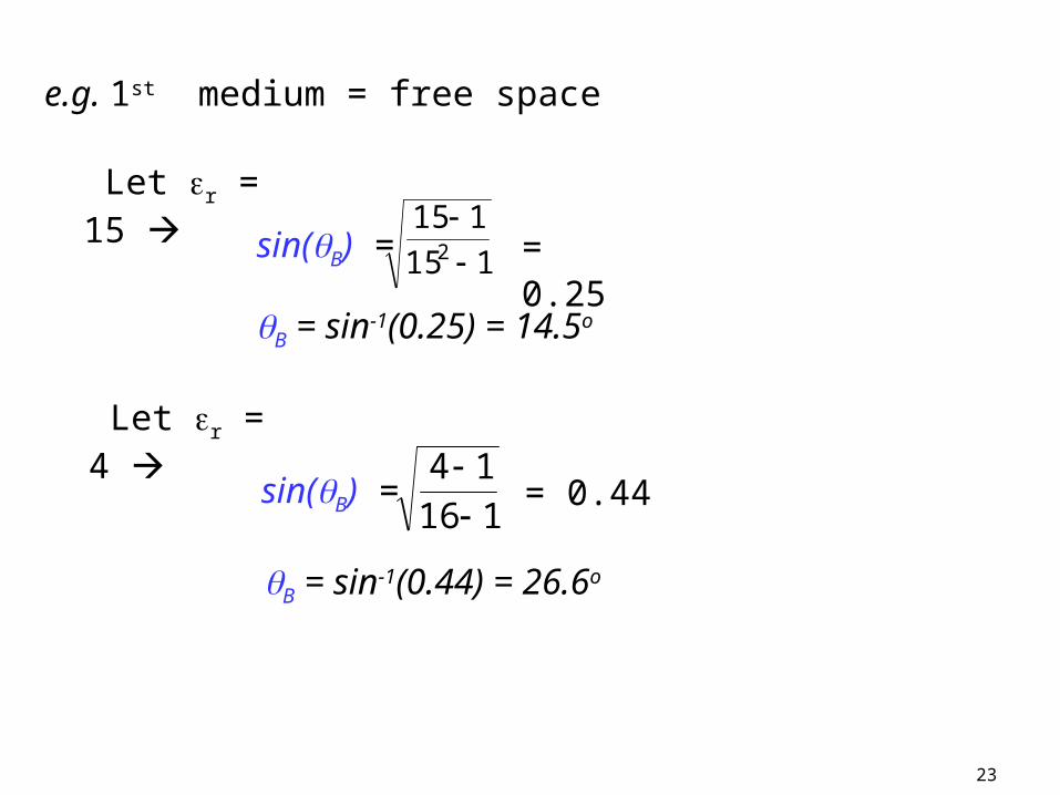
e.g. 1st medium = free space
Let r = 4
116
14
sin(B) = = 0.44
B = sin-1(0.44) = 26.6o
Let r = 15
115
1152
sin(B) = = 0.25
B = sin-1(0.25) = 14.5o
24
3.6 Ground Reflection – 2 Ray Model
Free Space Propagation model is inaccurate for most mobile RF channels
2 Ray Ground Reflection model considers both LOS path & ground reflected path
• based on geometric optics• reasonably accurate for predicting large scale signal strength for distances of several km
• useful for - mobile RF systems which use tall towers (> 50m)- LOS microcell channels in urban environments
Assume • maximum LOS distances d 10km • earth is flat
25
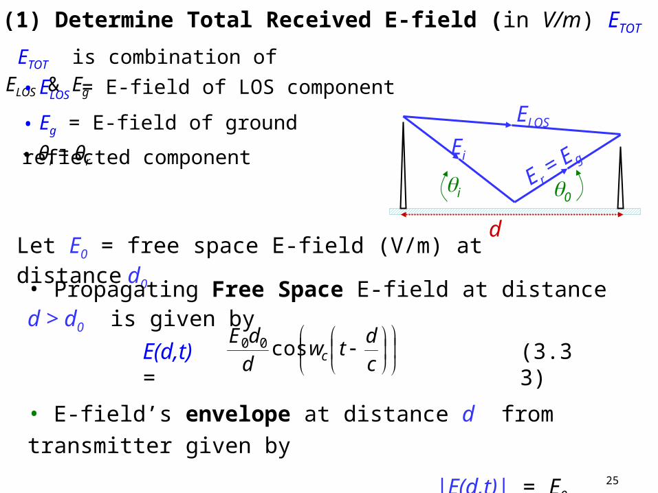
Let E0 = free space E-field (V/m) at distance d0
• Propagating Free Space E-field at distance d > d0 is given by
E(d,t) =
c
dtw
d
dEccos00 (3.33)
• E-field’s envelope at distance d from transmitter given by
|E(d,t)| = E0 d0/d
(1) Determine Total Received E-field (in V/m) ETOT
ELOS
Ei
E r = E g
i 0
d
ETOT is combination of ELOS & Eg
• ELOS = E-field of LOS component
• Eg = E-field of ground reflected component
• θi = θr
26
d’
d”
ELOS
Ei
E gi 0
d
ht h r
E-field for LOS and reflected wave relative to E0 given by:
and ETOT = ELOS + Eg
ELOS(d’,t) =
c
dtw
d
dEc
'cos
'00 (3.34)
Eg(d”,t) =
c
dtw
d
dEΓ c
"cos
"00 (3.35)
assumes LOS & reflected waves arrive at the receiver with - d’ = distance of LOS wave - d” = distance of reflected wave
27
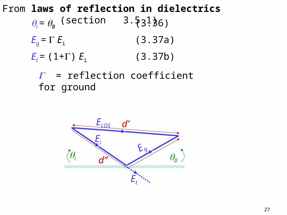
From laws of reflection in dielectrics (section 3.5.1)
i = 0 (3.36)
Eg = Ei (3.37a)
Et = (1+) Ei (3.37b)
= reflection coefficient for ground
E g
d’
d”
ELOS
Ei
i 0
Et
28
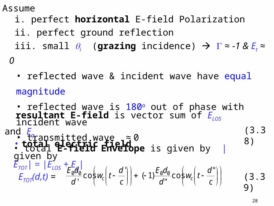
resultant E-field is vector sum of ELOS and Eg
• total E-field Envelope is given by |ETOT| = |ELOS + Eg| (3.38)
• total electric field given by
c
dtw
d
dEc
'cos
'00
c
dtw
d
dEc
"cos
")1( 00 (3.39)ETOT(d,t) =
Assume i. perfect horizontal E-field Polarization
ii. perfect ground reflection
iii. small i (grazing incidence) ≈ -1 & Et ≈ 0
• reflected wave & incident wave have equal magnitude
• reflected wave is 180o out of phase with incident wave
• transmitted wave ≈ 0
29
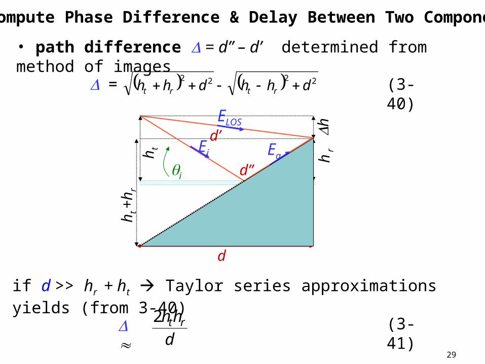
• path difference = d” – d’ determined from method of images
2222dhhdhh rtrt = (3-40)
if d >> hr + ht Taylor series approximations yields (from 3-40)
d
hh rt2 (3-41)
(2) Compute Phase Difference & Delay Between Two Components
ELOS
d
d’
d”i 0
ht
h r
h
ht +
h r
Ei Eg
30
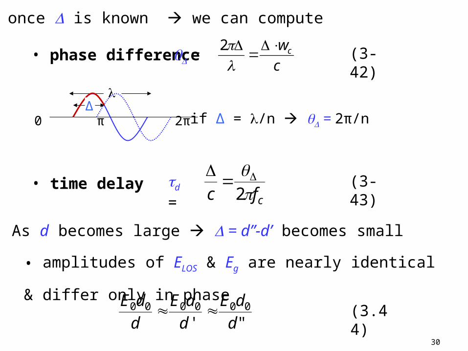
once is known we can compute
• phase difference =c
wc
2
(3-42)
• time delay d =cfc
2
(3-43)
As d becomes large = d”-d’ becomes small
• amplitudes of ELOS & Eg are nearly identical & differ only in phase
"'000000
d
dE
d
dE
d
dE (3.44)
if Δ = /n = 2π/n 0 π 2π
Δ
31
(3) Evaluate E-field when reflected path arrives at receiver
0cos"
)1('"
cos'
0000
d
dE
c
ddw
d
dEc
(3.45)ETOT(d,t)|t=d”/c =
t = d”/c reflected path arrives at receiver at
1cos00
cw
d
dEc
1cos00 d
dE=
100 d
dE=
32
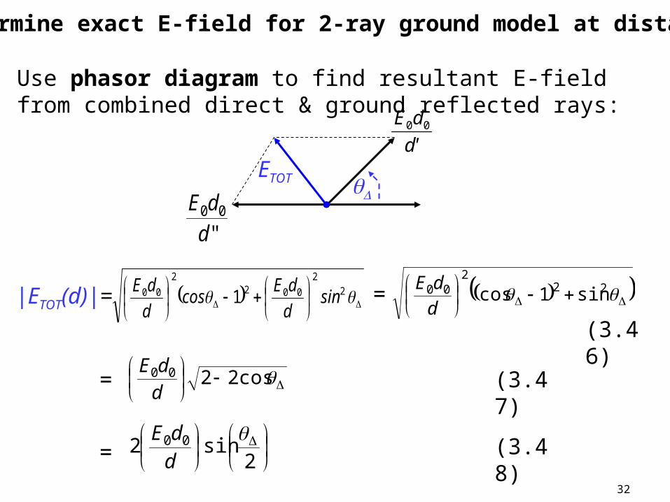
(3.46)
22
200 sin1cos
d
dE=
2
2
0022
00 1 sind
dEcos
d
dE|ETOT(d)|=
=
=
2sin2 00
d
dE
cos2200
d
dE(3.47)
(3.48)
ETOT
"00
d
dE
'd
dE 00
Use phasor diagram to find resultant E-field from combined direct & ground reflected rays:
(4) Determine exact E-field for 2-ray ground model at distance d
33
As d increases ETOT(d) decreases in oscillatory manner
• local maxima 6dB > free space value
• local minima ≈ - dB (cancellation)
• once d is large enough θΔ < π & ETOT(d) falls off asymtotically with increasing d
-50
-60-70
-80
-90
-100
-110-120
-130
-140101 102 103 104 m
fc = 3GHzfc = 7GHzfc = 11GHz
Propagation Loss ht = hr = 1, Gt = Gr = 0dB
34
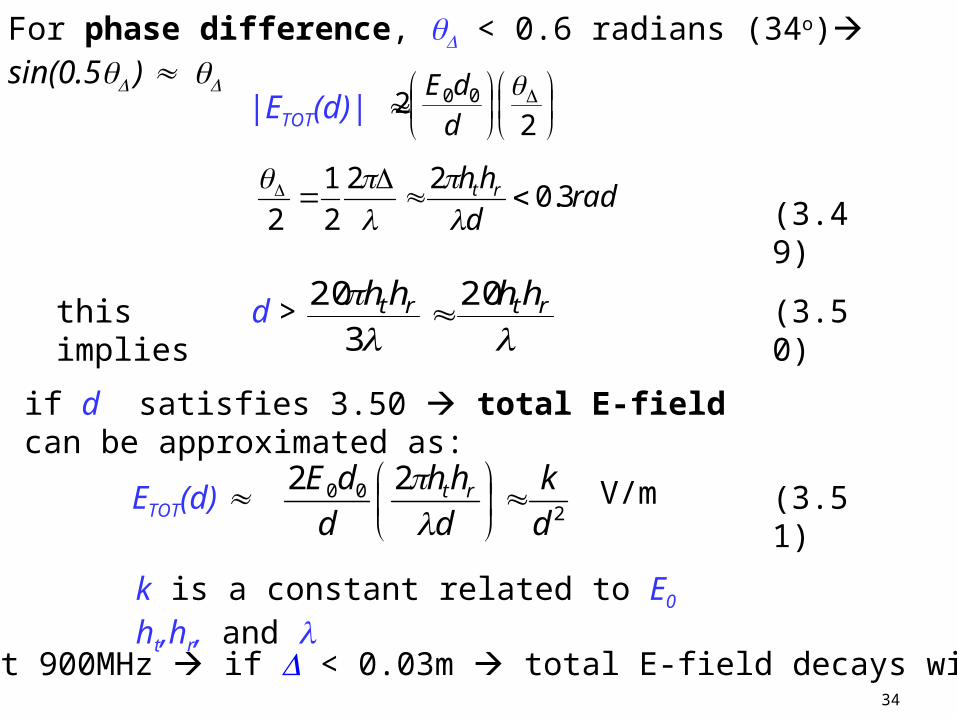
if d satisfies 3.50 total E-field can be approximated as:
k is a constant related to E0 ht,hr, and
radd
hh rt 3.022
2
1
2
(3.49)
d > (3.50)
rtrt hhhh 20
3
20 this implies
For phase difference, < 0.6 radians (34o) sin(0.5 )
22 00
d
dE|ETOT(d)|
e.g. at 900MHz if < 0.03m total E-field decays with d2
200 22
d
k
d
hh
d
dE rt
(3.51)ETOT(d)
V/m
35
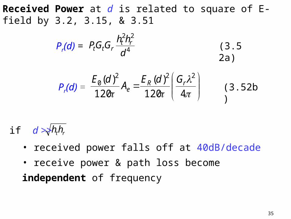
Received Power at d is related to square of E-field by 3.2, 3.15, & 3.51
Pr(d) = (3.52b)
4120
)(
120
)( 2220 rR
eGdE
AdE
Pr(d) = 4
22
d
hhGGP rt
rtt (3.52a)
• received power falls off at 40dB/decade
• receive power & path loss become independent of frequency
rthhif d >>
36
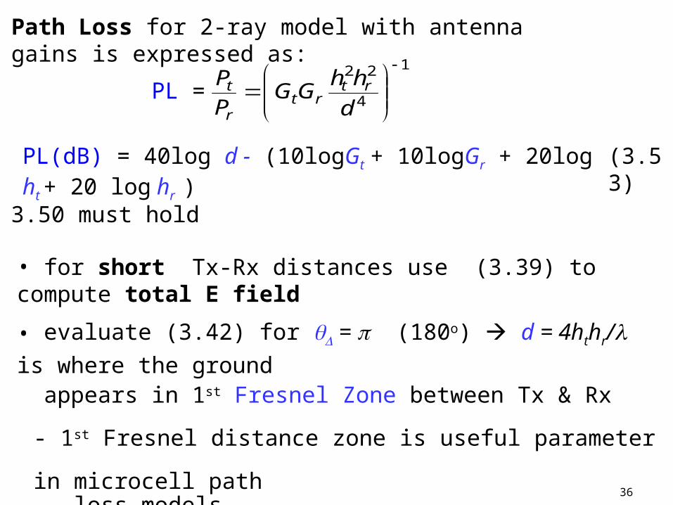
Path Loss for 2-ray model with antenna gains is expressed as:
• for short Tx-Rx distances use (3.39) to compute total E field
• evaluate (3.42) for = (180o) d = 4hthr/ is where the ground
appears in 1st Fresnel Zone between Tx & Rx
- 1st Fresnel distance zone is useful parameter in microcell path loss models