1 2045798 Rev C 1-3/8” Designer Metals Telescoping Traversing Rod Installation Instructions Please read and follow all installation instructions provided for proper operation and enjoyment of your new drapery hardware CONTENTS GETTING STARTED 1. Parts List 2. Recommended Tools 3. Fastener Guide 4. Rod Preparation For 2-Way Draw 5. One-Way Draw Conversion 5A. Right 1-way Draw 5B. Left 1-way Draw 6. Retainer Clip INSTALLATION 7. Bracket Installation 8. Finial Installation 9. Rod Installation 10. Lock Cam 11. Safety Tension Device Installation 12. Move Draw Cord Side 13. Centering the Master Carriers 14. Adjusting Cord Length 15. Hanging the Drapery 2-Way Draw 16. Hanging the Drapery 1-Way Draw
Transcript
12045798 Rev C
1-3/8” Designer MetalsTelescoping Traversing Rod Installation Instructions
Please read and follow all installation instructions provided for proper operationand enjoyment of your new drapery hardware
CONTENTS
GETTING STARTED 1. Parts List 2. Recommended Tools 3. Fastener Guide 4. Rod Preparation For 2-Way Draw 5. One-Way Draw Conversion 5A. Right 1-way Draw 5B. Left 1-way Draw 6. Retainer Clip
INSTALLATION 7. Bracket Installation 8. Finial Installation 9. Rod Installation10. Lock Cam11. Safety Tension Device Installation12. Move Draw Cord Side 13. Centering the Master Carriers14. Adjusting Cord Length15. Hanging the Drapery 2-Way Draw 16. Hanging the Drapery 1-Way Draw
2
SAFETY INFORMATION
GETTING STARTED
3
2 Drill with 3/32 bit1/4 Socket BitSQ2 Square Drive Bit LadderPencilScrewdriverPhillips ScrewdriverScissorsTape MeasureBubble Level
KIT235014
RECOMMENDED TOOLS (NOT INCLUDED)
1 PARTS LIST
GETTING STARTED
1
23
4
5
6
7
8
9
10
11
12
13
1
2
34
56
78
910
12
13
11
Inner Rod SectionOuter Rod Section
Overlap Master Carrier (Note: Some models do not have rings)
Underlap Master Carrier (Note: Some models do not have rings)
Ring Sliding Carrier (Note: Some models do not have rings)
Pulley System (2 included)
Retainer Plate (2 included)
Prong Bracket (2 included)
Center Bracket (Note: The number of brackets varies by length of rod)
Mounting Screws (Note: Screw quantity varies per number of brackets)
Draw CordSafety Tension Device
Finial Plug (2 included)
14 Safety Tension Device Mounting Kit
4
3 FASTENER GUIDE
4 ROD PREPARATION FOR 2-WAY DRAW
Slotted Hex Head screws provided for use in wood, and sheetmetal, or for use with anchor inserts (purchased seperately).
Use 3/32 inch drill bit for pilot hole with screws provided.
Use appropriate screw and anchor system that is rated for the total weight of the rod hardware and drapery material.
See the Kirsch Planning Guide at kirsch.com or your design professional to determine the width of your rod and the length it should be mounted above the floor or window to achieve your design goals.
Expand the inner and outer section to the desired width by pulling the sections in opposite directions.
The rod is shipped standard as a 2-way center draw. If converting to a 1-way draw see Section 5.
For split draw, the number of carriers required for each drapery panel should be equal to the number of pins in each drapery panel minus 3 (2 for mounting the drapery to the master carrier and 1 for mounting the drapery return at the bracket base).
GETTING STARTED
Center draw Left one-way draw
Count the number of carriers on each side of the master carriers and determine the number of carriers to be added or removed from the rod. Add or remove an equal amount of carriers on each side of the master carriers to equal the total number of carriers needed.
See the Kirsch Planning Guide at kirsch.com or your design professional to determine the weight of the drapery to be certain it does not exceed the rod limitations.
Mounting screws provided can be driven with a straight screwdriver, SQ2 square bit driver or a 1/4 inch nut driver.
RIGHT 1-WAY DRAW (see section 5B for Left 1-way Draw)
1-WAY DRAW CONVERSION (Skip this section if you desire a 2-way center draw rod and proceed to Section 6)
Determine to which side of rod you would like the draperies to draw.
The number of carriers needed should equal the number of pins in the drapery minus 3 (2 for mounting drapery to the master carrier and 1 for mounting the drapery return at the bracket base).
Lay the rod on the floor with the open side of the rod facing up.
5
Pull the two rod sections apart -- no more than 6”.
Remove and discard the underlap master carrier (which is the master carrier with no knots in the cord).Remove the overlap master carrier from the track but do not untie.Count the carriers and match to the number needed as determined earlier in step 5. Remove or add carriers to the track on the right side of the master carrier and reinstall the over-lap master carrier on the track.
Rejoin the inner and outer sections of the rod and set the overall width desired.
5A
5
GETTING STARTED
Remove carriers by pressing the pulley housing tab and sliding the carrier shoe through the opening to remove it from the rod. Add carriers by pressing the pulley housing tab and sliding the carrier shoe through the opening to add it to the rod.
GATE AREA
ADD OR REMOVE THRU GATE
Overlap Master Carrier
Move the overlap master carrier arm to the right screw hole position by removing the screw located in the arm and re-installing in the new position.
Remove the overlap master carrier arm, rotate it to the opposite direction, move it one position to the right and re-install the screw.
LEFT 1-WAY DRAW (see section 5A for Right 1-way Draw)
INSTALL RETAINER CLIP AND END CARRIER
The tab should not be used and should be broken off the retainer using pliers.
5B
Rejoin the inner and outer sections of the rod and set the overall width desired.
Count the carriers and match to the number needed as determined in step 5A. Remove or add carriers to the track on the left side of the overlap master carrier and reinstall the over-lap master carrier on the track.
Remove the overlap master carrier from the track but do not untie.
Remove and discard the underlap master carrier (which is the carrier with no knots in the cord).
Overlap Master Carrier
The retainers are to be installed at each end of the rod to clasp the pole together and secure the end plugs and last carrier.
6
6
BREAK OFF
End carrier to be placed between end plug and pulley system
Pulley System
Finial Plug
Retainer
Follow diagram for installation of end carrier
GETTING STARTED
BRACKET INSTALLATIONDetermine the placement of the rod according to the diagram.
Use the diagram below for reference to determine the length with your drapery treatment.
7
Rod Width
Sill
Apron
Floor
Length
Clearance3 inch minimum
For length, measure from the top edge of the end brackets (which is rod height) to determine the correct length that coordinated with your drapery treatment which could be floor length, apron length, sill length or other determined by your application.
Rod
2-5/16 inch
1/8 inch1/2 inch
Top Bracket HoleTop of Rod
Top of Drapery
DraperyDrapery Pin
Decorative Ring (available on some models)
Fluted Rod (Smooth Rod also available)
Drapery Pin Hole
1-3/4 inch
1/4 inch
Cross Section View
7
GETTING STARTED
For the width, take into consideration the end bracket prongs are placed 2” from the end of the each side of the rod.
Use a bubble level and mark the center support brackets level with the end brackets per the diagram.
2 inch
Maximum 18 inches between end bracket and first center support
Maximum 30 inches between center supports. Space cen-ter support brackets evenly.
Center Support Brackets
End Support Brackets
ROD INSTALLATION
FINIAL INSTALLATION (Purchased Separately)
Kirsch has a variety of finials available to attach to this rod. Screw the finial onto the rod at the end plug as shown.
8
8
Use assistance to install rod. Do not allow rod to bend. Do not install rod onto brackets with draperies attached.
The center support bracket forepart can be rotated to the side or pushed back to allow the rod to be installed on the end support prong brackets.
Be sure the bracket arms are loose before placing the rod onto the brackets to adjust the projection when mounted.
9
INSTALLATION
IN
OUT
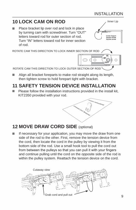
ROTATE CAM THIS DIRECTION TO LOCK OUTER SECTION OF ROD
ROTATE CAM THIS DIRECTION TO LOCK INNER SECTION OF ROD
Inner Lip
Align all bracket foreparts to make rod straight along its length, then tighten screw to hold forepart tight with bracket.
If necessary for your application, you may move the draw from one side of the rod to the other. First, remove the tension device from the cord, then locate the cord in the pulley by viewing it from the bottom side of the rod. Use a small hook tool to pull the cord out from between the pulleys so that you can pull it with your fingers and continue pulling until the cord on the opposite side of the rod is within the pulley system. Reattach the tension device on the cord.
Grab cord and pull out
Cutaway view
9
Please follow the installation instructions provided in the install kit, KIT2350 provided with your rod.
10 LOCK CAM ON RODPlace bracket lip over rod and lock in place by turning cam with screwdriver. Turn “OUT” letters toward rod for outer section of rod. Turn “IN” letters toward rod for inner section of rod.
12 MOVE DRAW CORD SIDE (optional)
SAFETY TENSION DEVICE INSTALLATION11
INSTALLATION
Remove any slack in the cord, by pulling the cord taught.
10
13 CENTERING THE MASTER CARRIERS (2-way center draw only)
Use the cord to draw the master carriers to each end of the pole. Push the carriers to the end if necessary.
Hold the cord taut, and slip the cord under the T-shaped hook located on the underlap master carrier.
Locate the underlap master carrier (the carrier with NO knots in the cord).
ADJUSTING CORD LENGTH14 Locate the overlap master carrier.
Tie a new knot as close as possible to the back of the rod.
Test the new length by opening and closing the drapery.
Repeat these steps if performance was not satisfactory.
Cord cannot be reattached after it has been cut.
If certain the length is correct, proceed to cut the extra cord after the knot near the carrier.
On the back side of the rod and overlap master carrier are two knots in the cord. To adjust the cord length, pull the knot closes to the end of the rod with the draw cord loop until it is taut.
Knots
Pull cord out until taut
INSTALLATION
End Pin Right Panel
End Pin Left Panel
End Pin on Drapery 2nd to Last Pin
on Drapery
Pins must already be placed in the drapery approximately 1/2 inch from the top of the drapery treatment. (See diagram in section 7)
Move the carriers to the closed position, and evenly space your carriers along the rod to make installing the drapery easier. Start at the master carrier by placing the the end pin at the end of the master carrier and the next to end pin in the next hole in the master carrier, then place 1 pin in each carrier hole. Refer to the diagram below.
Place the next to last pin in the last carrier hole and the end pin in the hole on the bracket.
HANGING THE DRAPERY (2-way center draw only)15
11
Repeat the above instructions for the other panel on the opposite side of the rod.Test the installation for proper operation and make adjustments as necessary.
Step back and enjoy your new Kirsch hardware!
Carrier Hole
Last Carrier placed between Pulley System and End Plug
See Section 16 for hanging the drapery on a 1-way draw rod.
INSTALLATION
End Pin Left Panel
End Pin on Drapery 2nd to Last Pin
on Drapery
Pins must already be placed in the drapery approximately 1/2 inch from the top of the drapery treatment. (See diagram in section 7)
Move the carriers to the closed position, and evenly space your carriers along the rod to make installing the drapery easier. Start at the master carrier by placing the the end pin at the end of the master carrier and the next to end pin in the next hole in the master carrier, then place 1 pin in each carrier hole. Refer to the diagram below.
Place the next to last pin in the last carrier hole and the end pin in the hole on the bracket.
HANGING THE DRAPERY (1-way draw only)16
Test the installation for proper operation and make adjustments as necessary.
Step back and enjoy your new Kirsch hardware!
Carrier Hole
Last Carrier placed between Pulley System and End Plug
Note: Left 1-way draw shown, reverse for Right 1-way draw.