51
1 | 51 Communication Systems 13 th lecture Chair of Communication Systems Department of Applied Sciences University of Freiburg 2008
| Date post: | 27-Dec-2015 |
| Category: |
Documents |
| Upload: | ethel-austin |
| View: | 214 times |
| Download: | 1 times |

1 | 51
Communication Systems13th lecture
Chair of Communication SystemsDepartment of Applied Sciences
University of Freiburg2008
2 | 51
Communication SystemsExam, exercise sheet
Everybody (who likes to take exam in communication systems) should have registered for it – next chance is winter semester – we repeat the lecture in modified form (as a succession of “Systeme II” held in summer term by Prof. Schindelhauer)
Next lecture: 4th July (exercise sheet #6 – available from the web page – is due for that date)
Next practical: 8th, 11th July

3 | 51
Communication SystemsLast lecture – GSM data services, GPRS, EDGE
Standardization of GPRS was important cornerstone for the development of UMTS network
GPRS defines an add-on for data services within the GSM networks - packet orientated approach to data switching
Allocation of channels request-driven
Todays bandwidth of 53,6 kbit/s (4 full rate traffic channels à 13,4 kbit/s), up to 107,2 kbit/s with 8 channels (more with EDGE as discussed in last lecture)
GPRS usually operates asynchronous with more bandwidth for down than for upstream
GPRS bases on an additional infrastructure: GSN – GPRS Support Nodes as an extension to GSM
SGSN (Serving GSN), GGSN (Gateway GSN)

4 | 51
Communication SystemsLast lecture – GSM data services, GPRS
Main GSM components, like MSC, VLR and HLR used for GPRS too, additional infrastructure: GSN – GPRS Support Nodes

5 | 51
Communication SystemsLast lecture – GSM, logical structure of the network
SGSN – serving GSN to support the MSC for localization, billing and security
GGSN – gateway GSN is the gateway to the packet data network – usually the Internet
GR – GPRS register to support the HLR (home location register), used for user address mapping
Several new interface definition between network components
6 | 51
Communication SystemsPlan for this lecture
UMTS as the world wide 3G mobile standard Short history of developments, todays and future revisions
Network architecture and interfaces
User equipment and USIM
Core network functionality and protocols (packet switched and circuit switched domain)
UTRAN – UTMS radio network subsystem RNS, RNC, Node B
Network based and connection based functions
Power control and hand-over
Authentication and security
7 | 51
Communication SystemsFrom GSM to 3rd generation mobile networks
The short comings of GSM led to the development of a next generation mobile network
The new network Should use the scarce resources of the shared medium “air”
more efficiently Should be really international (GSM had a primarily scope on
Europe first) Much higher data rates should be offered with reduced delays
Preferring the packet orientated approach over the circuit switched one – data services play an increasing role in mobility and voice could be just seen as data too (in reality is – voice is digitized and sent in packets in GSM already)

8 | 51
Communication SystemsIMT2000 and UMTS
International Telecommunication Union (ITU) defined demands for third generation mobile networks with the IMT-2000 standard
3GPP (3G Partnership Project) continued that work by defining a mobile system that fulfills the IMT-2000 standard
Resulting system is called Universal Mobile Telecommunications System (UMTS)
Release '99 defined the bearer services with 64 kbit/s circuit switched and up to 384 kbit/s packet switched data rates
Location services and call services were defined: GSM-compatibility should be offered, the authentication and security will be upgraded to USIM

9 | 51
Communication SystemsUMTS
Several different paths from 2G to 3G defined In Europe the main path starts from GSM when GPRS was added to
the system
From this point it is possible to go to the UMTS system as we will see in core network structure of UMTS next lecture
In North America the system evolution will start from TDMA going to EDGE (last lecture) and from there to UMTS
In Japan (the blind spot of GSM) two different 3G standards used W-CDMA (which is compatible with UMTS) by NTT DoCoMo,
Vodafone KK, and by new entrants

10 | 51
Communication SystemsUMTS
cdma2000 (not compatible to European standards) which is very successfully used by KDDI
Transition to 3G was largely completed in Japan during 2005/2006 UMTS system bases on layered services, like IP but unlike GSM
Top is the services layer, which will give advantages like fast deployment of services and centralized location
In the middle layer is control layer, which will help upgrading procedures and allow the capacity of the network to be dynamically allocated
11 | 51
Communication SystemsUMTS
Bottom layer is handled by the connectivity layer where any transmission technology can be used and the voice traffic will transfer over ATM/AAL2 or IP/RTP
UTMS will converge the mobile phone networks towards the IP world
Thus ATM is just the old existing traditional infrastructure used
Using IP in UMTS might push the IP world toward IPv6, because there will be a huge number of mobile phone subscribers (which might even exceed the number of IP dial-in Internet users)
A lot of GSM infrastructure will be reused in UMTS networks nevertheless, more on radio network, W-CDMA next lecture!

12 | 51
Communication SystemsUMTS – history and planned standards
Requirements toward a 3G standard Fully specified and world-widely valid
Major interfaces should be standardized and open Services must be independent from radio access technology and
is not limited by the network infrastructure Support of multimedia content and all of its components Convergence of existing networks
13 | 51
Communication SystemsUMTS – history and planned standards
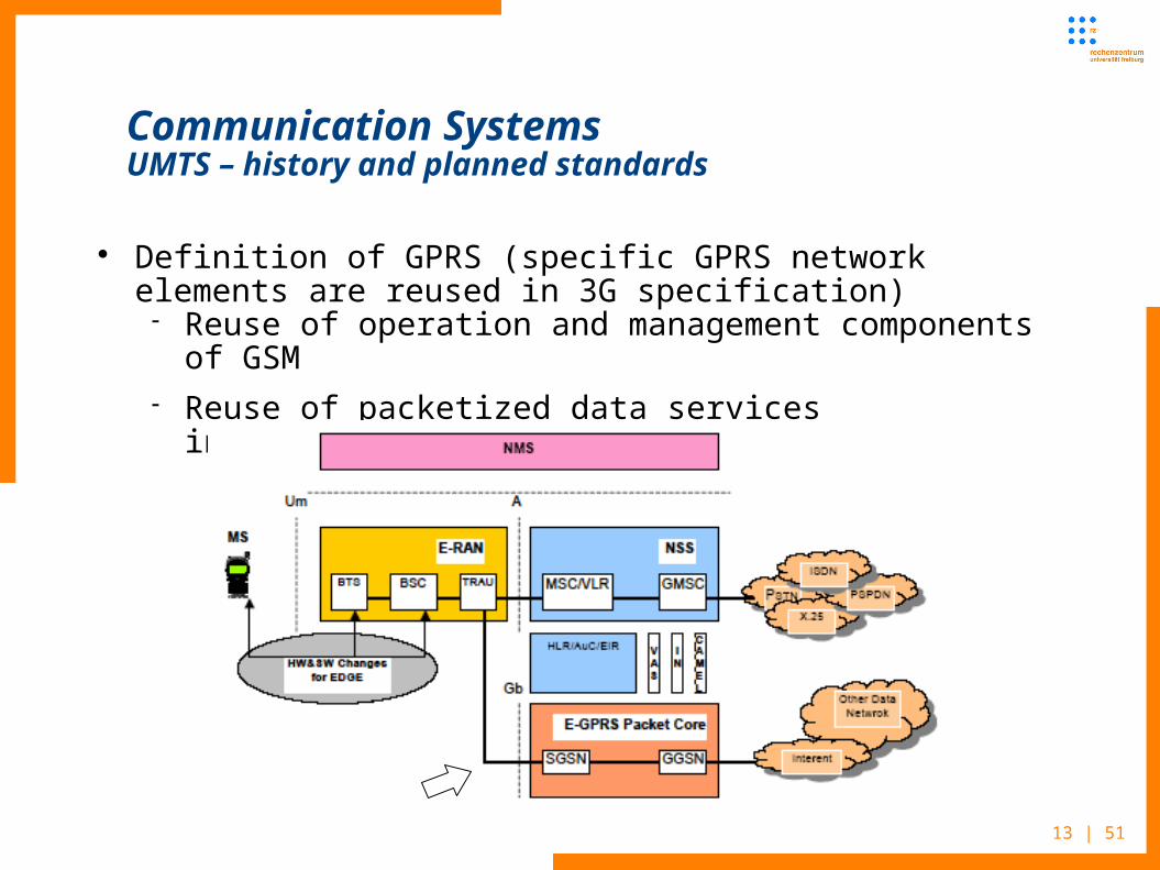
Definition of GPRS (specific GPRS network elements are reused in 3G specification) Reuse of operation and management components of GSM Reuse of packetized data services infrastructure of GPRS

14 | 51
Communication SystemsUMTS – history and planned standards
February 1995 UMTS Task Force established; "The Road to UMTS" report
December 1996 The UMTS Forum established. "European" WCDMA standard known as Universal Mobile Telecommunications System (UMTS)
June 1997 UMTS Forum produces first report: "A regulatory Framework for UMTS"
October 1997 ERC decided on UMTS core band. January 1998 ETSI meeting: W-CDMA and TD-CDMA proposals
combined to UMTS air interface specification

15 | 51
Communication SystemsUMTS – history and planned standards
June 1998 Terrestrial air interface proposals (UTRAN, WCDMA(s), CDMA2000(s), EDGE, EP-DECT, TD-SCDMA) were handed into ITU-R
3GPP Release ‘99

16 | 51
Communication SystemsUMTS – history and planned standards
December 1999 in Nice ETSI Standardization finished for UMTS Release 1999 specifications both for FDD and TDD
March 2001 in Palm Springs 3GPP approves UMTS Release 4 specification

17 | 51
Communication SystemsUMTS – history and planned standards
Release 4 and 5 specifies an “All IP standard” Streaming services (fast handover) Seamless UMTS/WLAN integration, inter-working Push-to-Talk over cellular Presence for chat, instant messaging, ...
18 | 51
Communication SystemsUMTS – history and planned standards
Release 6 Extended location based services (LBS), with built in
anonymization Packet switches streaming services, with adaptation to
available network resources (GERAN/GPRS, UTMS, WLAN) Of course :-) DRM Charging Management Framework (for extended payment
systems) For more see www.3gpp.org

19 | 53
Communication SystemsUMTS network architecture and interfaces
UTMS network architecture has several similarities to GSM, but you will find different names for some components
As for GSM in UMTS several interfaces are defined UE – user equipment means more generally any UMTS enabled
(mobile) device
20 | 53
Communication SystemsUMTS network domains
User Equipment Domain handles the access of the user onto the UMTS services
USIM – User Services Identity Module Extended SIM functionality Functions for user identification, authentication and encryption Integrated into SIM card (of the established format) Most recent Mobile Equipment can handle both SIM and USIM
Mobile Equipment Domain responsible for air interface User interface for end-to-end connections
21 | 53
Communication SystemsUMTS network domains - CN
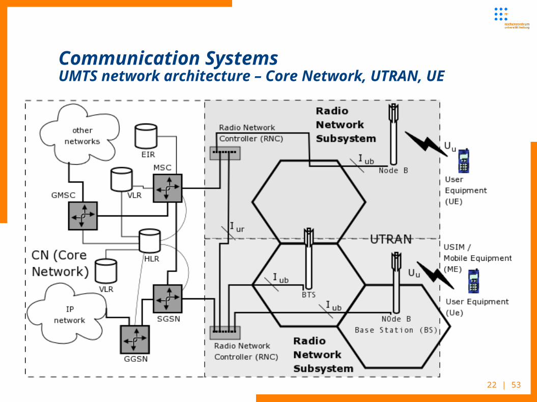
Infrastructure Domain Shared between all users Offers services to all authenticated users
CN – Core Network the (mobile) telephony back-end infrastructure Functions which are independent on access network Handover between different systems Location management if there is no dedicated link between
UE and UTRAN Inter-connection of different bearer networks
22 | 53
Communication SystemsUMTS network architecture – Core Network, UTRAN, UE

23 | 53
Communication SystemsUMTS network domains - CN
CN infrastructure consists of Serving network domain – network which actually provides the
user access Home network domain – functionality and information which is
independent of actual user location Transit network domain – infrastructure between several
network components, different kind of networks and different network providers, operators

24 | 53
Communication SystemsUMTS network domains - CN
CN infrastructure split into two logical networks Both may serve the two different radio networks via either
BSC and RNS Circuit switched domain (CSD)
IuCS interface Traditional circuit switched data connection and signaling Resource reservation on connection setup GSM components (MSC, GMSC, HLR, VLR, EIR, ...)
25 | 53
Communication SystemsUMTS network domains - CN
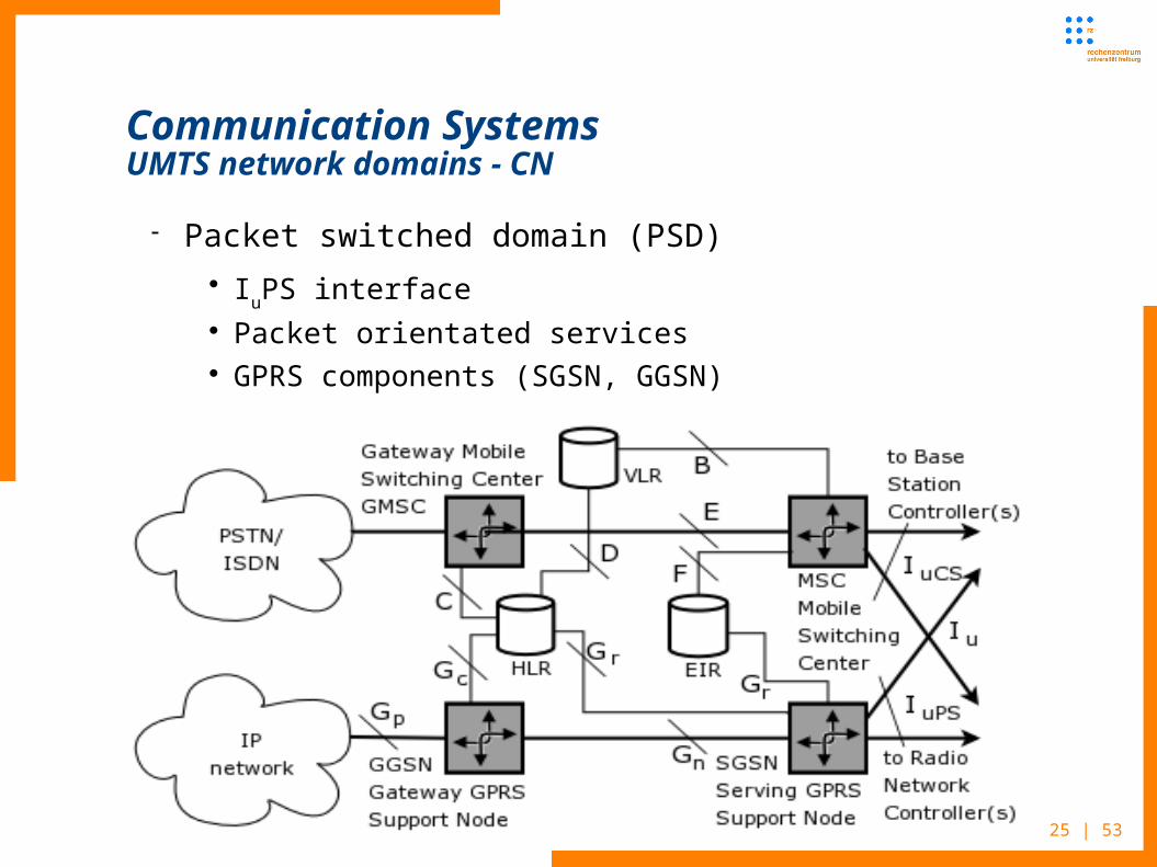
Packet switched domain (PSD) I
uPS interface
Packet orientated services GPRS components (SGSN, GGSN)

26 | 53
Communication SystemsUMTS network – packet switching domain
The UTMS packet switching domain protocol stack follows the GPRS design
27 | 53
Communication SystemsUMTS network - UTRAN
UTRAN (UTRA network) is the UMTS transceiver radio interface network part Manages mobility on cell level – handover decision Composed of several Radio Network Subsystems (RNS)
connected to the Core Network through the lu interface
Every Radio Network Subsystem is managed by Radio Network Controller (RNC) RNC also handles radio resource management (RRM)
operations
RNC is responsible for the local handover process and the combining/multicasting functions related to macro diversity between different Node-Bs (Drift RNC - DRNC)
28 | 53
Communication SystemsUTRAN - RNS
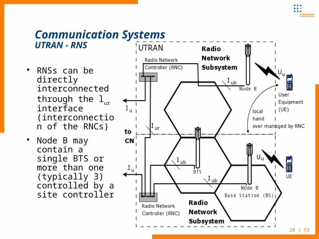
RNSs can be directly interconnected through the lur interface (interconnection of the RNCs)
Node B may contain a single BTS or more than one (typically 3) controlled by a site controller
29 | 53
Communication SystemsUMTS network - UTRAN
UTRAN functions Controls cell capacity and interference in order to provide an
optimal utilization of the wireless interface resources Includes Algorithms for Power Control, Handover, Packet
Scheduling, Call Admission Control and Load Control Encryption of the radio channel Congestion control to handle situations of network overload System information broadcasting Micro and macro diversity (explained later)

30 | 53
Communication SystemsUMTS network - UTRAN
Network based functions Packet Scheduling
Controls the UMTS packet access Handles all non real time traffic, (packet data users) Decides when a packet transmission is initiated and the bit rate
to be used Load Control
Ensures system stability and that the network does not enter an overload state
Admission control to avoid network overload Decides whether or not a call is allowed to generate traffic in the
network

31 | 53
Communication SystemsUTRAN network function – Load Control
Power Control
32 | 53
Communication SystemsUMTS network - UTRAN
Connection based functions Power Control
Manages radio link quality - Uplink is handled per mobile (UE), downlink per physical channel
Ensures that transmission powers are kept at a minimum level and that there is adequate signal quality and level at the receiving end
Handover guarantees user mobility in a mobile communications network SRNS (Serving RNS) relocation
33 | 53
Communication SystemsUTRAN - connection based functions
Power Control handles Setting of transmit power to keep QoS in required limits
(regarding data rate, delay, BER, ...) Path loss (near-far problem), shadowing (log-normal fading) Fast fading (Rayleigh-, Rican-Fading) Environment (delay spread, UE speed) which implies different
performance of the de-interleaver and decoder Three types: Inner loop, outer loop (SIR-target adjusting), open
loop (power allocation) Open-Loop Power Control
Rough estimation of path loss from receiving signal Initial power setting, or when no feedback channel exist

34 | 51
Communication SystemsUTRAN - connection based functions
Closed-Loop Power Control Feedback loop with 1.5kHz cycle to
adjust uplink / downlink power to its minimum
Even faster than the speed of Rayleigh fading for moderate mobile speeds
Outer Loop Power Control Adjust the target SIR (Signal to
Interference Ratio) setpoint in base station according to the target BER, commanded by RNC

35 | 51
Communication SystemsUTRAN - connection based functions
UMTS provides several handover procedures Intra Node B handover (softer) Inter Node B handover, inter-frequency, intra-frequency (hard
and soft) Inter RNC (hard, soft and soft-softer) Inter MSC Inter SGSN Inter System (UMTS - GSM)
Hard Handover Connection to a Node B is destroyed before a new one (to an
other Node B is started)

36 | 51
Communication SystemsUTRAN - connection based functions
Soft Handover A MS is in the overlapping coverage of 2 different base stations
(Node B) Concurrent communication via 2 air interface channels Downlink: Maximal combining with rake receiver Uplink: Routed to RNC for selection combining, according to a frame
reliability indicator by the base station

37 | 51
Communication SystemsUTRAN - connection based functions
Softer Handover A MS is in the overlapping coverage of 2 sectors of a base
station Concurrent communication via 2 air interface channels 2 channels are maximally combined with rake receiver
Soft Softer Handover Soft and softer handover combined
Inter system handover from UMTS to GSM or vice versa RNS the UE is connected to is the Serving RNS RNS which provides additional resources, e.g for handover
procedure is Drift RNS
38 | 51
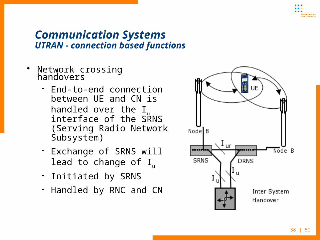
Communication SystemsUTRAN - connection based functions
Network crossing handovers End-to-end connection
between UE and CN is handled over the Iu interface of the SRNS (Serving Radio Network Subsystem)
Exchange of SRNS will lead to change of Iu
Initiated by SRNS Handled by RNC and CN
39 | 51
Communication SystemsUTRAN – Base Stations (Node B) – Radio Interface
Base Station – Node B Mainly handles physical layer tasks
Main task of node B is to establish the physical implementation of the U
u interface (communication with the UE) and the
implementation of Iub
interface (Communication with the RNC)
Providing the Uu interface means that the Base Station implements
WCDMA radio access Physical Channels and transfer information from Transport Channels to the Physical Channels based on arrangements determined by the RNC
The term Physical Channels means different kinds of bandwidth allocated for different purposes over U
u interface

40 | 51
Communication SystemsUMTS - Air Interface
UTMS uses Wideband CDMA (Code Division Multiple Access) on two different duplex mechanisms
CDMA allows frequency reuse factor of 1 (GSM 4 ... 18) 5MHz Bandwidth allows multipath diversity using „Rake Receiver“
Variable Spreading Factor (VSF) to offer Bandwidth on Demand (BoD) up to 2MHz
Fast (1.5kHz) Power Control for Optimal Interference Reduction
Services multiplexing with different QoS Real-time / Best-effort
10% Frame Error Rate to 10-6 Bit Error Rate

41 | 51
Communication SystemsUMTS – QoS classes
Background download of emails
Web browsing,network games
Streaming multimedia
Voice, videotelephony, video games
Example of the application
Destination is not expecting the data within a certain time
Preserve data integrity
Request response pattern
Preserve data integrity
Preserve time relation between information entities of the stream
Preserve time relation between information entities of the stream
Conversational pattern (stringent and low delay)
Fundamental characteristics
BackgroundInteractive class
Streaming class
Conversational class
Traffic class

42 | 51
Communication SystemsUMTS – Rake Receiver
Radio receiver designed to counter the effects of multipath fading rake receiver is so named because of its analogous function to
a garden rake, each finger collecting bit or symbol energy similarly to how tines on a rake collect leaves
Commonly used in a wide variety of CDMA and W-CDMA radio devices

43 | 51
Communication SystemsUMTS – Rake Receiver
Radio receiver Uses several "sub-receivers" each delayed slightly in order to tune in
to the individual multipath components
Each component decoded independently, but at a later stage combined in order to make the most use of the different transmission characteristics of each path
Results in higher Signal-to-noise ratio (or Eb/No) in a multipath environment than in a "clean" environment
Multipath fading is a common problem in wireless networks especially in metropoletan areas
Another “trick” to increase connection quality and reliability is macro diversity
44 | 51
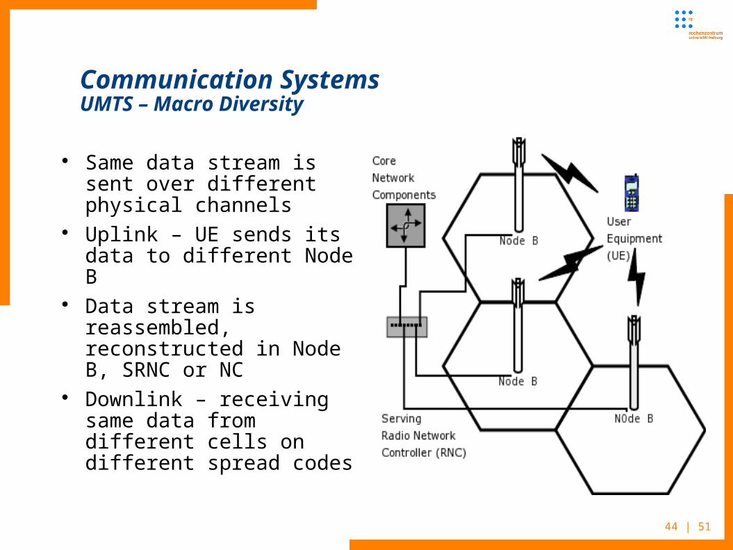
Communication SystemsUMTS – Macro Diversity
Same data stream is sent over different physical channels
Uplink – UE sends its data to different Node B
Data stream is reassembled, reconstructed in Node B, SRNC or NC
Downlink – receiving same data from different cells on different spread codes
45 | 51
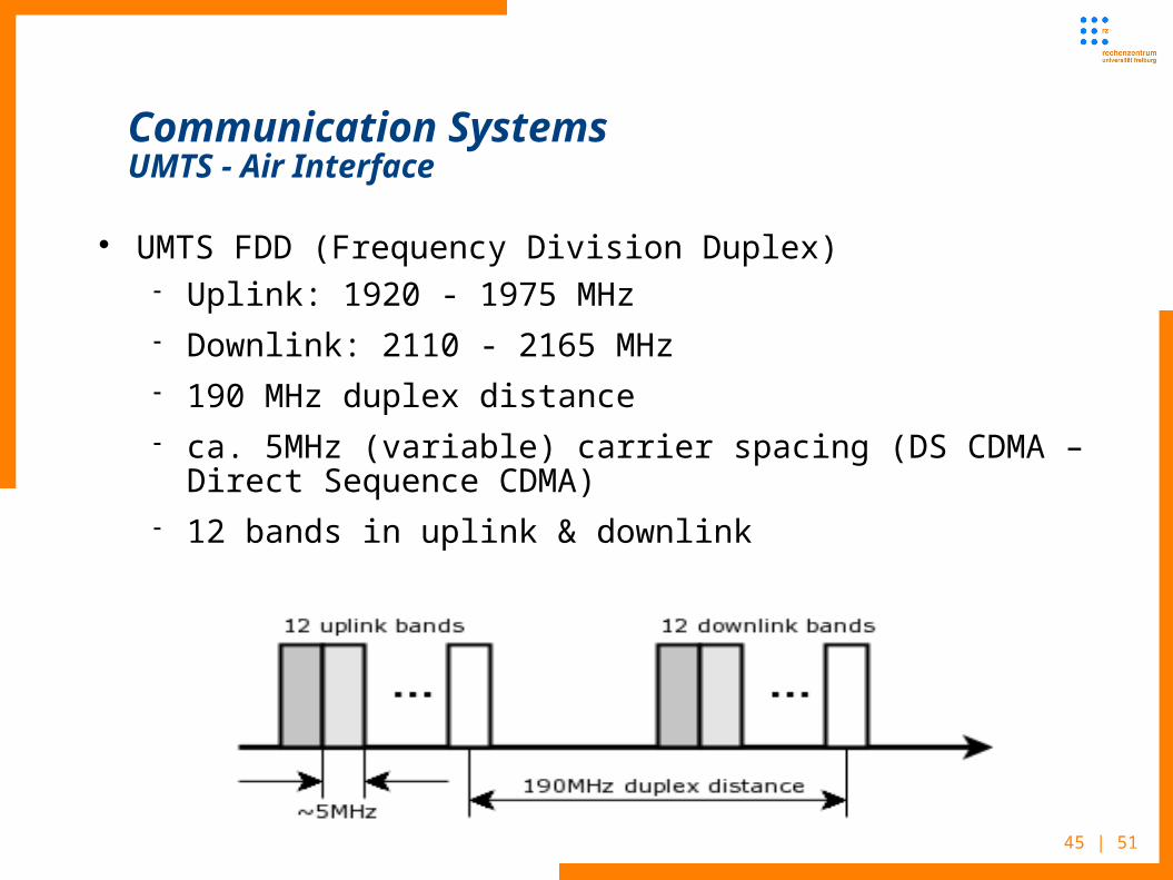
Communication SystemsUMTS - Air Interface
UMTS FDD (Frequency Division Duplex) Uplink: 1920 - 1975 MHz Downlink: 2110 - 2165 MHz 190 MHz duplex distance ca. 5MHz (variable) carrier spacing (DS CDMA – Direct
Sequence CDMA) 12 bands in uplink & downlink

46 | 51
Communication SystemsUMTS - Air Interface
UMTS TDD (Time Division Duplex) Uplink & Downlink: 1900 - 1920 MHz and 2020 - 2025 MHz
5 carriers in total, 15 timeslots per frame a user may use one or several timeslots a timeslot can be assigned to either uplink or downlink

47 | 51
Communication SystemsUMTS – Cell Breathing
Advantages of UMTS W-CDMA Power Control - solves the near-far problem
Soft capacity, dynamic cell sizes Different to GSM, where
fixed cell size Number of logged in users has no influence on cell size
In UMTS cell size is tightly interrelated with its capacity Size depends on signal/noise ratio because of both maximum
TX power and number of active users (interference in the same cell through other users and with other cells) which results in cell breathing

48 | 51
Communication SystemsUMTS – Cell Breathing
Interference increases noise in signal UE on the cell edge is transmitting with max power Another UE becomes active – results in increased interference The received signal from the UE on the cell edge is too weak
and communication becomes impossible Restriction of participants needed Effective cell size decreases with increasing number of users There is a trade-off between capacity and coverage Results in cell breathing and imposes greater difficulties on
network planning
49 | 51
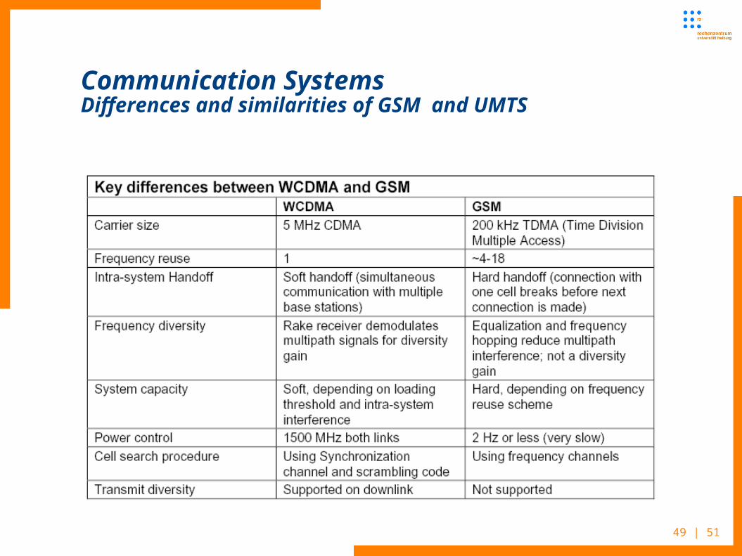
Communication SystemsDifferences and similarities of GSM and UMTS
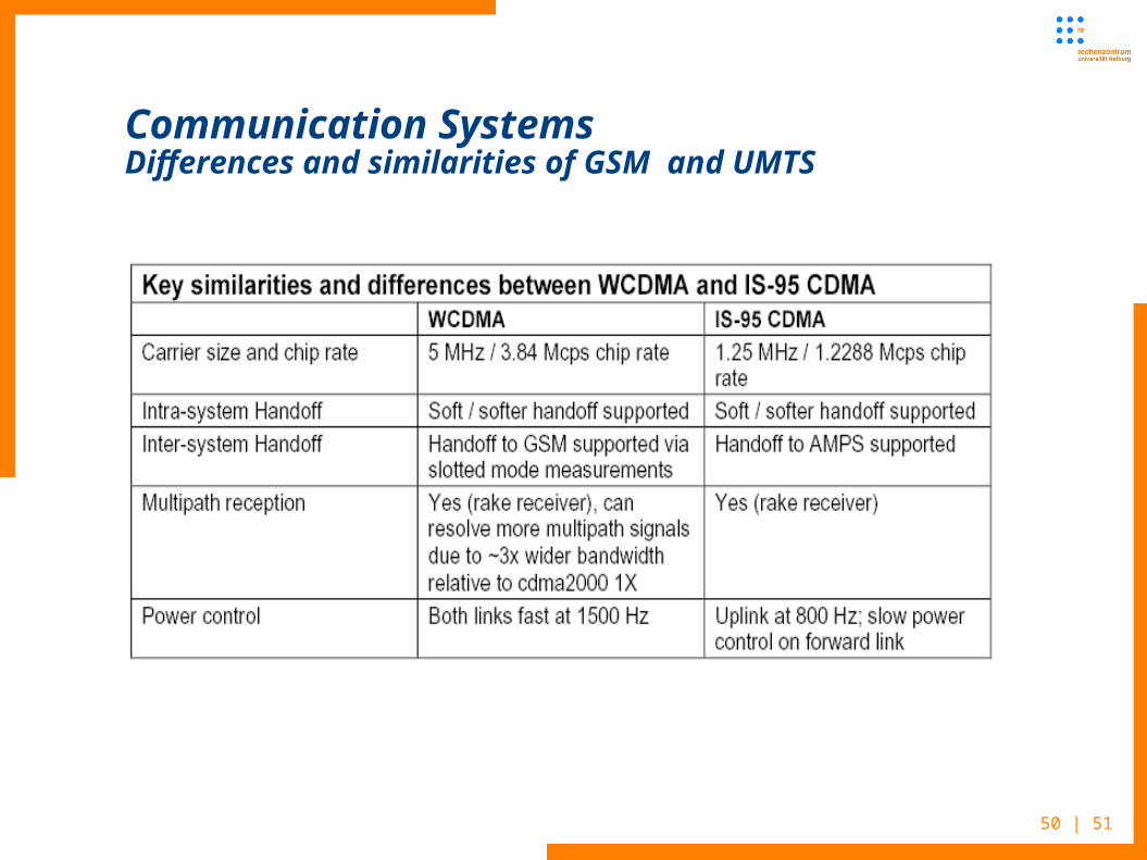
50 | 51
Communication SystemsDifferences and similarities of GSM and UMTS

51 | 51
Communication SystemsUMTS literature
Text books (german): Jochen Schiller, Mobilkommunikation Bernhard Walke, Mobilfunknetze und ihre Protokolle,
Grundlagen GSM, UMTS, ... Link (see seminar slides and papers):
http://www.ks.uni-freiburg.de/download/papers/telsemWS05/UMTS-nextGeneration/UMTS-Seminararbeit-Stefan%20Nagy.pdf


