23
OPERATION AND SERVICE MANUAL 1 9 9 9 T O WER DRYER PNEG-526 12’, 18’, 24’ & 30’ DIAMETER DRYER MODELS G S I G R A I N C O N D I T I O N I N G S Y S T E M S
1
Tower Dryer Ops & Service
OPERATION AND SERVICE MANUAL
1 9 9 9TOWER DRYER
PNEG-52612', 18', 24' & 30'DIAMETER DRYER
MODELS
G S I G R A I N C O N D I T I O N I N G S Y S T E M S

2
Tower Dryer Ops & Service

3
Tower Dryer Ops & Service
DRYER OPERATIONSafety First..............................................................................................................4Safety Features............................................................................................................5Safety Precautions......................................................................................................6GSI Tower Dryer Cutaway........................................................................................7Installation Requirements........................................................................................8Electrical................................................................................................................8Fuel........................................................................................................................8Dryer Control Panel ...................................................................................................9Dryer Start Up.......................................................................................................11Dryer Shutdown.........................................................................................................13Electronic Monitoring Control Operation.............................................................14
Turning On The Electronic Monitoring Control System...............................14The Electronic Monitoring Control System Display Screen...........................14Setting The Out Of Grain Timer....................................................................15Setting The Load And Unload Delays............................................................15Utilizing The Bushel Counter........................................................................15Modifying The Bushel Per Hour Factor.........................................................15Displaying The Dryer Hour Meter.................................................................15Dryer Safety Circuit......................................................................................15Displaying The Dryer Safety Shutdown Log.................................................15Electronic Monitoring Control System Messages.........................................15
MAINTENANCEPre-Seasonal Inspection And Service...................................................................16
Lubrication Table...........................................................................................16Seasonal Inspection And Service.........................................................................17
In Case Of Fire..................................................................................................17End Of Season Service.......................................................................................17
TROUBLE SHOOTINGTrouble Analysis Procedure.................................................................................18
WARRANTY..............................................................................................................23ELECTRICAL DIAGRAMSCOMPONENT MANUALS
Toshiba Compact InverterMaxon Series "NP" & "RG" AIRFLO BurnersProtectofier Service ManualHoneywell Modutrol IV MotorsRockwell 121 RegulatorHansen Transmissions-Service Manual Geared Motors And Gear UnitsASCO Solenoid ValvesFISHER Single And Second-Stage LP-Gas RegulatorsHoneywell UDC2000 Mini-Pro Universal Digital Controller Product Manual
Troubleshooting/Service Section
TABLE OF CONTENTS
4
Tower Dryer Ops & ServiceSAFETY FIRST
This manual contains information that is important for you, the owner/operator, to know andunderstand. This information relates to protecting personal safety and preventing
equipment problems. It is the responsibility of the owner/operator to inform anyoneoperating or working in the area of this equipment of these safety guidlines.To help you
recognize this information, we use the symbols that are defined below.Please read the manual and pay attention to these sections. Failure to read this manualand it�s safety instructions is a misuse of the equipment and may lead to serious injury or
death.
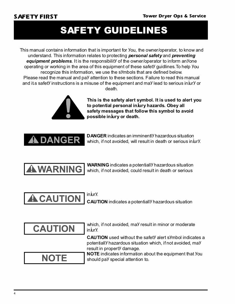
SAFETY GUIDELINES
DANGER indicates an imminently hazardous situationwhich, if not avoided, will result in death or serious injury.
This is the safety alert symbol. It is used to alert youto potential personal injury hazards. Obey allsafety messages that follow this symbol to avoidpossible injury or death.
WARNING indicates a potentially hazardous situationwhich, if not avoided, could result in death or serious
injury.
CAUTION indicates a potentially hazardous situation
which, if not avoided, may result in minor or moderateinjury.
CAUTION used without the safety alert symbol indicates apotentially hazardous situation which, if not avoided, mayresult in property damage.NOTE indicates information about the equipment that youshould pay special attention to.
5
Tower Dryer Ops & Service SAFETY FIRSTThe GSI Group, Inc.'s principle
concern is your safety and the safety
of others associated with grain han-
dling equipment. This manual was
written with that thought in mind.
We want to keep you as a customer
by helping you understand
safeoperating proceedures, and
some of the problems that may be
encountered by the dryer operator
or other personnel.
As owner and/or operator, it is
your responsibility to know what re-
quirements, hazards and precau-
tions exist, and to inform all per-
sonnel associated with the equipment
or who are in the dryer area. Avoid
any alterations to the equipment.
Such alterations may produce a very
dangerous situation, where serious
injury or death may occur.
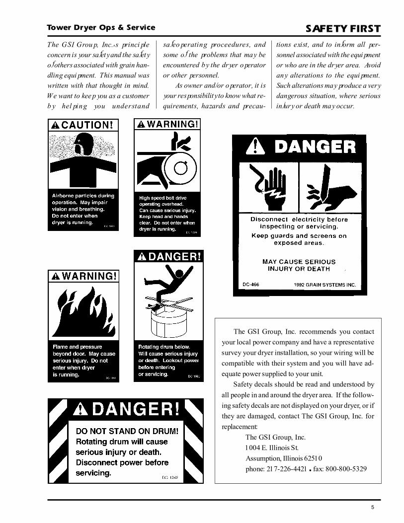
The GSI Group, Inc. recommends you contact
your local power company and have a representative
survey your dryer installation, so your wiring will be
compatible with their system and you will have ad-
equate power supplied to your unit.
Safety decals should be read and understood by
all people in and around the dryer area. If the follow-
ing safety decals are not displayed on your dryer, or if
they are damaged, contact The GSI Group, Inc. for
replacement:
The GSI Group, Inc.
1004 E. Illinois St.
Assumption, Illinois 62510
phone: 217-226-4421 � fax: 800-800-5329

6
Tower Dryer Ops & Service
1. Read and understand the operating manual before trying to operate
the dryer.
2. Never operate the dryer while any guards are removed.
3. Power supply should be OFF for service of electrical compo-
nents. Use CAUTION in checking voltage or other procedures requir-
ing power to be ON.
4. Check for gas leaks at all gas pipe connections. If any leaks are
detected, do not operate dryer. Shut down and repair before fur-
ther operation.
5. Never attempt to operate the dryer by jumping or otherwise bypassing
any safety devices on the unit.
6. Do not exceed maximum recommended drying temperatures.
7. Keep the dryer clean. Do not allow fine material to accumulate in
the plenum chamber.
8. Keep blower drive belts tight enough to prevent slippage.
9. Use CAUTION in working around high speed fans, gas burners, augers
and auxiliary conveyors which START AUTOMATICALLY.
10. Do not operate in any area where combustible material will be drawn into
the fan.
11. Be certain that capacities of auxiliary conveyors are matched to dryer
metering capacities.
12. Clean grain is easier to dry. Fine material increases resistance to airflow
and requires removal of extra moisture.
13. Do not adjust any moving part on the dryer while it is running.
Use Caution In TheOperation Of This Equipment
The design and manufacture of this
dryer is directed toward operator
safety. However, the very nature of
a grain dryer having a gas burner,
high voltage electrical equipment
and high speed rotating parts, does
present a hazard to personnel, which
can not be completely safeguarded
against, without interfering with ef-
ficient operation and reasonable ac-
cess to components.
Use extreme caution in working
around high speed fans, gas-fired
heaters, augers and auxiliary con-
veyors.
Continued safe, dependable opera-
tion of automatic equipment de-
pends, to a great degree, upon the
owner. For a safe and dependable
drying system, follow the recom-
mendations within this manual, and
make it a practice to regularly in-
spect the operation of the unit for
any developing problems or unsafe
conditions.
Take special note of the safety
precautions listed above before at-
tempting to operate the dryer.
READ THESE INSTRUCTIONSBEFORE OPERATION AND SERVICE
SAVE FOR FUTURE REFERENCE
KEEP THE DRYER CLEAN
DO NOT ALLOW FINE
MATERIAL TO
ACCUMULATE IN THE
PLENUM CHAMBER
OR SURROUNDING THE
OUTSIDE OF THE DRYER
SAFETY PRECAUTIONS

7
Tower Dryer Ops & Service
Inside and outsidesafety ladders, cagesand catwalks providesafe and easy accessto all areas of thedryer
Recycling heat fromthe cooling grainresults in significantfuel savings
Walk-in cool sectionprovides easy accessto blowers andmetering system
Stainless steel, rollformed, exteriorsheeting promoteslong dryer life andimproved dryerappearance
Heavy-duty overallconstruction resultsin an extra rigidstructure in aminimum of groundspace
Reducer cone equalizesair velocity pastburners for optimumcombustion andprovides step-in accessto burner assembly
Large wet holdinggarner bin is sealedto help retain graindust and bees wings
Industrial qualitycomponents (includ-ing Maxon valvesand burners) ensureyears of reliableservice
"Patented" dischargesystem providessimple, uniformmetering and quickdryer clean out
Walk-in heat sectionprovides easy accessfor interior cleaning
"Patented" ElectronicMonitoring ControlSystem provides themost advanced andreliable dryer controlon the market
Weather-proofNEMA IV cabinetsand NEMA ratedelectrical compo-nents ensure safe andreliable operation inall conditions
In-line Maxon NP1series burnersprovide even heatand efficient combus-tion from eithernatural gas or LPvapor (fuel oilburners are optional)
12" wide graincolumns and longgrain retention timesresult in high quality,efficiently driedgrain
Internally mountedtubular centrifugalblowers deliver highvolumetric airflow tothe pressure heat andsuction cool sections
Internal mountingprovides the addedbenefit of ultra quietoperation as thesurrounding graincreates a naturalnoise barrier
Divider hopperseparates the heatingand cooling sectionswhile preventingbuild-up of particu-late matter
Grain turners in eachcolumn ensure evendrying
GSI TOWER DRYER CUTAWAY

8
Tower Dryer Ops & Service
Figure 1: The grain dryer control panel with the Electronic Monitoring Control System in the upper panel.
DRYER CONTROL PANEL
2
3
45
6
7
9 10
8 11
12
14
13
1
A
B
J
I
D E GFC
H

9
Tower Dryer Ops & Service
Dryer Control Panel Featuring TheElectronic Monitoring Control System
1. Electronic Monitoring Control System controlsall the dryer's timing functions and safety circuitchecks. It provides messages and warnings on itsliquid crystal display (LCD).
2. Plenum Temperature Control controls andindicates drying temperature.
3. Moisture Control Thermostat controls themetering drum discharge speed automatically whenthe MOISTURE CONTROL switch is set to "AUTO".
4. Moisture Control Switch selects automatic ormanual control of the metering drum speed.
5. Metering Drum Speed controls the meteringdrum discharge speed when the MOISTURE CON-TROL switch is set to "MANUAL".
6. Control Power Switch energizes the control paneland the Electronic Monitoring Control System.
7. Outside Light Switch turns the dryer service lighton or off. On "AUTO", the light turns on when thedryer is running and off when a shutdown occurs.
8. Load Switch controls the filling of the dryer. The"MANUAL" position initially fills the dryer. The"OFF" position turns the conveyor off/shuts the slidegate. The "AUTO" position enables automatic fillcontrol and the OUT OF GRAIN TIMER.
On dryers filled on demand with a conveyor:In the "MANUAL" or "AUTO" position the fillconveyor turns on when the dryer is low on grainand off when the dryer is full.In the "AUTO" position only, the dryer willautomatically shut down when the dryer is low ongrain and the OUT OF GRAIN TIMER expires.
On dryers filled on demand with a slide gate:In the "MANUAL" and "AUTO" position the fillslide gate opens when the dryer is low on grainand shuts when the dryer is full.In the "AUTO" position only, the dryer willautomatically shut down when the dryer is low ongrain and the OUT OF GRAIN TIMER expires.
On choke filled dryers:In the "AUTO" position only, the dryer willautomatically shut down when the dryer is low ongrain and the OUT OF GRAIN TIMER expires.In the "MANUAL" or "OFF" position the OUTOF GRAIN TIMER is disabled.
The LOAD switch is illuminated whenever the lowergrain level indicator senses grain.
9. Fan(s) Switch turns the blower(s) on or off. Onmultifan dryers, the blower run through a staggeredstartup. The switch is illuminated when all of theblower airflow switches close indicating that theblowers are operating correctly.
10. Burner Switch turns the burner on or off. Whenthe switch is turned on, the dryer automatically goesthrough a 60 second purge cycle followed by theautomatic lighting of the burner pilot. The switchilluminates when flame is sensed at the pilot. After thepilot flame is established, the Maxon shut off valvesare energized and must be openned manually tosupply gas to the main burner.
11. Unload Dry Grain Conveyor Switch turns theunload conveyor on or off. The switch illuminateswhen the conveyor is operating.
12. Metering Drum Switch turns the metering drumon or off in forward or reverse. The drum will not runforward unless the unload conveyor is on. The switchilluminates when the metering drum is discharginggrain.
13. Dryer Power Start Button initiates automaticoperation of the dryer. When depressed, the dryerbegins the startup cycle and operates based on thepositions of the selector switches on the control panel.
To control the operation of individual components,first depress the DRYER POWER START button,then turn on the individual dryer components asdesired.
14. Dryer Power Stop Switch manually stops all dryerfunctions and automatic equipment.Important: In case of an automatic dryer shutdown,the DRYER POWER STOP button must be depressedto reset the dryer control circuit before the dryer canbe restarted.
DRYER CONTROL PANEL
10
Tower Dryer Ops & ServiceDRYER START UP
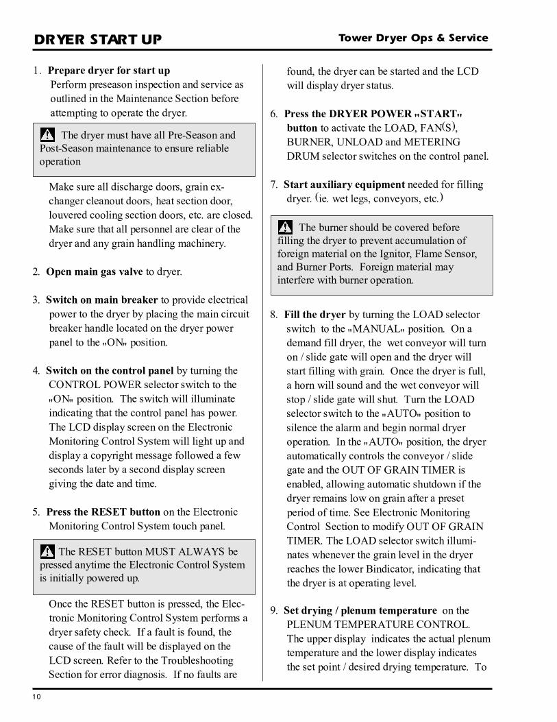
1. Prepare dryer for start upPerform preseason inspection and service asoutlined in the Maintenance Section beforeattempting to operate the dryer.
found, the dryer can be started and the LCDwill display dryer status.
6. Press the DRYER POWER "START"button to activate the LOAD, FAN(S),BURNER, UNLOAD and METERINGDRUM selector switches on the control panel.
7. Start auxiliary equipment needed for fillingdryer. (ie. wet legs, conveyors, etc.)
8. Fill the dryer by turning the LOAD selectorswitch to the "MANUAL" position. On ademand fill dryer, the wet conveyor will turnon / slide gate will open and the dryer willstart filling with grain. Once the dryer is full,a horn will sound and the wet conveyor willstop / slide gate will shut. Turn the LOADselector switch to the "AUTO" position tosilence the alarm and begin normal dryeroperation. In the "AUTO" position, the dryerautomatically controls the conveyor / slidegate and the OUT OF GRAIN TIMER isenabled, allowing automatic shutdown if thedryer remains low on grain after a presetperiod of time. See Electronic MonitoringControl Section to modify OUT OF GRAINTIMER. The LOAD selector switch illumi-nates whenever the grain level in the dryerreaches the lower Bindicator, indicating thatthe dryer is at operating level.
9. Set drying / plenum temperature on thePLENUM TEMPERATURE CONTROL.The upper display indicates the actual plenumtemperature and the lower display indicatesthe set point / desired drying temperature. To
Once the RESET button is pressed, the Elec-tronic Monitoring Control System performs adryer safety check. If a fault is found, thecause of the fault will be displayed on theLCD screen. Refer to the TroubleshootingSection for error diagnosis. If no faults are
Make sure all discharge doors, grain ex-changer cleanout doors, heat section door,louvered cooling section doors, etc. are closed.Make sure that all personnel are clear of thedryer and any grain handling machinery.
2. Open main gas valve to dryer.
3. Switch on main breaker to provide electricalpower to the dryer by placing the main circuitbreaker handle located on the dryer powerpanel to the "ON" position.
4. Switch on the control panel by turning theCONTROL POWER selector switch to the"ON" position. The switch will illuminateindicating that the control panel has power.The LCD display screen on the ElectronicMonitoring Control System will light up anddisplay a copyright message followed a fewseconds later by a second display screengiving the date and time.
5. Press the RESET button on the ElectronicMonitoring Control System touch panel.
The burner should be covered beforefilling the dryer to prevent accumulation offoreign material on the Ignitor, Flame Sensor,and Burner Ports. Foreign material mayinterfere with burner operation.
The RESET button MUST ALWAYS bepressed anytime the Electronic Control Systemis initially powered up.
The dryer must have all Pre-Season andPost-Season maintenance to ensure reliableoperation
11
Tower Dryer Ops & Service DRYER START UP
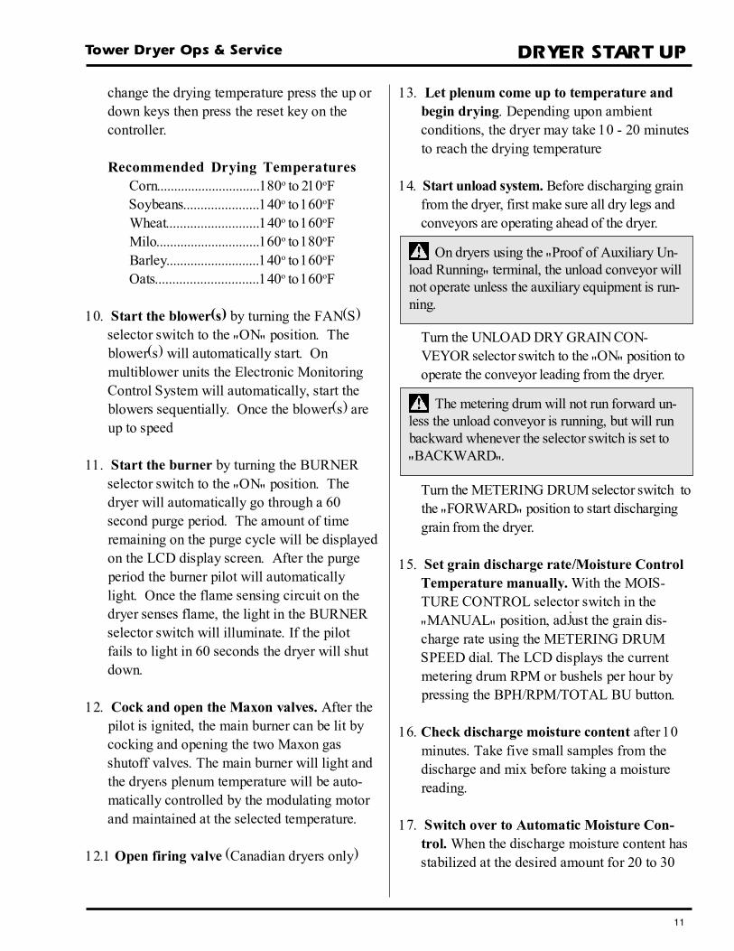
change the drying temperature press the up ordown keys then press the reset key on thecontroller.
Recommended Drying TemperaturesCorn..............................180o to 210oFSoybeans......................140o to 160oFWheat...........................140o to 160oFMilo..............................160o to 180oFBarley...........................140o to 160oFOats..............................140o to 160oF
10. Start the blower(s) by turning the FAN(S)selector switch to the "ON" position. Theblower(s) will automatically start. Onmultiblower units the Electronic MonitoringControl System will automatically, start theblowers sequentially. Once the blower(s) areup to speed
11. Start the burner by turning the BURNERselector switch to the "ON" position. Thedryer will automatically go through a 60second purge period. The amount of timeremaining on the purge cycle will be displayedon the LCD display screen. After the purgeperiod the burner pilot will automaticallylight. Once the flame sensing circuit on thedryer senses flame, the light in the BURNERselector switch will illuminate. If the pilotfails to light in 60 seconds the dryer will shutdown.
12. Cock and open the Maxon valves. After thepilot is ignited, the main burner can be lit bycocking and opening the two Maxon gasshutoff valves. The main burner will light andthe dryer's plenum temperature will be auto-matically controlled by the modulating motorand maintained at the selected temperature.
12.1 Open firing valve (Canadian dryers only)
13. Let plenum come up to temperature andbegin drying. Depending upon ambientconditions, the dryer may take 10 - 20 minutesto reach the drying temperature
14. Start unload system. Before discharging grainfrom the dryer, first make sure all dry legs andconveyors are operating ahead of the dryer.
Turn the UNLOAD DRY GRAIN CON-VEYOR selector switch to the "ON" position tooperate the conveyor leading from the dryer.
Turn the METERING DRUM selector switch tothe "FORWARD" position to start discharginggrain from the dryer.
15. Set grain discharge rate/Moisture ControlTemperature manually. With the MOIS-TURE CONTROL selector switch in the"MANUAL" position, adjust the grain dis-charge rate using the METERING DRUMSPEED dial. The LCD displays the currentmetering drum RPM or bushels per hour bypressing the BPH/RPM/TOTAL BU button.
16. Check discharge moisture content after 10minutes. Take five small samples from thedischarge and mix before taking a moisturereading.
17. Switch over to Automatic Moisture Con-trol. When the discharge moisture content hasstabilized at the desired amount for 20 to 30
The metering drum will not run forward un-less the unload conveyor is running, but will runbackward whenever the selector switch is set to"BACKWARD".
On dryers using the "Proof of Auxiliary Un-load Running" terminal, the unload conveyor willnot operate unless the auxiliary equipment is run-ning.
12
Tower Dryer Ops & ServiceDRYER SHUTDOWN
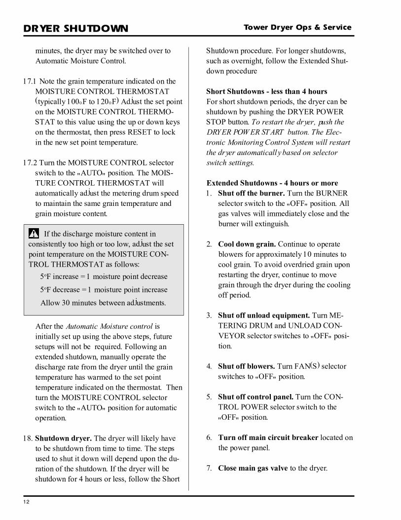
minutes, the dryer may be switched over toAutomatic Moisture Control.
17.1 Note the grain temperature indicated on theMOISTURE CONTROL THERMOSTAT(typically 100°F to 120°F) Adjust the set pointon the MOISTURE CONTROL THERMO-STAT to this value using the up or down keyson the thermostat, then press RESET to lockin the new set point temperature.
17.2 Turn the MOISTURE CONTROL selectorswitch to the "AUTO" position. The MOIS-TURE CONTROL THERMOSTAT willautomatically adjust the metering drum speedto maintain the same grain temperature andgrain moisture content.
After the Automatic Moisture control isinitially set up using the above steps, futuresetups will not be required. Following anextended shutdown, manually operate thedischarge rate from the dryer until the graintemperature has warmed to the set pointtemperature indicated on the thermostat. Thenturn the MOISTURE CONTROL selectorswitch to the "AUTO" position for automaticoperation.
18. Shutdown dryer. The dryer will likely haveto be shutdown from time to time. The stepsused to shut it down will depend upon the du-ration of the shutdown. If the dryer will beshutdown for 4 hours or less, follow the Short
Shutdown procedure. For longer shutdowns,such as overnight, follow the Extended Shut-down procedure
Short Shutdowns - less than 4 hoursFor short shutdown periods, the dryer can beshutdown by pushing the DRYER POWERSTOP button. To restart the dryer, push theDRYER POWER START button. The Elec-tronic Monitoring Control System will restartthe dryer automatically based on selectorswitch settings.
Extended Shutdowns - 4 hours or more1. Shut off the burner. Turn the BURNER
selector switch to the "OFF" position. Allgas valves will immediately close and theburner will extinguish.
2. Cool down grain. Continue to operateblowers for approximately 10 minutes tocool grain. To avoid overdried grain uponrestarting the dryer, continue to movegrain through the dryer during the coolingoff period.
3. Shut off unload equipment. Turn ME-TERING DRUM and UNLOAD CON-VEYOR selector switches to "OFF" posi-tion.
4. Shut off blowers. Turn FAN(S) selectorswitches to "OFF" position.
5. Shut off control panel. Turn the CON-TROL POWER selector switch to the"OFF" position.
6. Turn off main circuit breaker located onthe power panel.
7. Close main gas valve to the dryer.
If the discharge moisture content inconsistently too high or too low, adjust the setpoint temperature on the MOISTURE CON-TROL THERMOSTAT as follows:
5oF increase = 1 moisture point decrease
5oF decrease = 1 moisture point increase
Allow 30 minutes between adjustments.
13
Tower Dryer Ops & Service ELECTRONIC MONITORING CONTROL
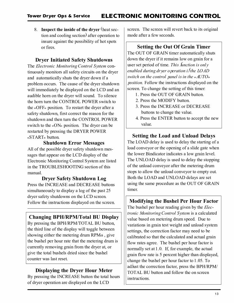
Dryer Initiated Safety ShutdownsThe Electronic Monitoring Control System con-tinuously monitors all safety circuits on the dryerand automatically shuts the dryer down if aproblem occurs. The cause of the dryer shutdownwill immediately be displayed on the LCD and anaudible horn on the dryer will sound. To silencethe horn turn the CONTROL POWER switch tothe "OFF" position. To restart the dryer after asafety shutdown, first correct the reason for theshutdown and then turn the CONTROL POWERswitch to the "ON" position. The dryer can berestarted by pressing the DRYER POWER"START" button.
Shutdown Error MessagesAll of the possible dryer safety shutdown mes-sages that appear on the LCD display of theElectronic Monitoring Control System are listedin the TROUBLESHOOTING section of thismanual.
Dryer Safety Shutdown LogPress the INCREASE and DECREASE buttonssimultaneously to display a log of the past 25dryer safety shutdowns on the LCD screen.Follow the instructions displayed on the screen.
8. Inspect the inside of the dryer (heat sec-tion and cooling section) after operation toinsure against the possibility of hot spotsor fires.
screen. The screen will revert back to its originalmode after a few seconds.
Setting the Out Of Grain TimerThe OUT OF GRAIN timer automatically shutsdown the dryer if it remains low on grain for auser set period of time. This function is onlyenabled during dryer operation if the LOADswitch on the control panel is in the "AUTO"position. Follow the instructions displayed on thescreen. To change the setting of this timer:
1. Press the OUT OF GRAIN button.2. Press the MODIFY button.3. Press the INCREASE or DECREASE
buttons to change the value.4. Press the ENTER button to accept the new
value.
Setting the Load and Unload DelaysThe LOAD delay is used to delay the starting of aload conveyor or the opening of a slide gate whenthe lower Bindicator indicates a low grain level.The UNLOAD delay is used to delay the stoppingof the unload conveyor after the metering drumstops to allow the unload conveyor to empty out.Both the LOAD and UNLOAD delays are setusing the same procedure as the OUT OF GRAINtimer.
Modifying the Bushel Per Hour FactorThe bushel per hour reading given by the Elec-tronic Monitoring Control System is a calculatedvalue based on metering drum speed. Due tovariations in grain test weight and unload systemsettings, the correction factor may need to becalibrated so that the calculated and actual grainflow rates agree. The bushel per hour factor isnormally set at 1.0. If, for example, the actualgrain flow rate is 5 percent higher than displayed,change the bushel per hour factor to 1.05. Toadjust the correction factor, press the BPH/RPM/TOTAL BU button and follow the on screeninstructions.
Changing BPH/RPM/Total BU DisplayBy pressing the BPH/RPM/TOTAL BU button,the third line of the display will toggle betweenshowing either the metering drum RPM's , givethe bushel per hour rate that the metering drum iscurrently removing grain from the dryer at, orgive the total bushels dried since the bushelcounter was last reset.
Displaying the Dryer Hour MeterBy pressing the INCREASE button the total hoursof dryer operation are displayed on the LCD

14
Tower Dryer Ops & ServiceMAINTENANCE
1Lubrication of motors--Operate motors for 20 minutes. Clean grease fitting. Remove grease relief plug and using a low pressure greasegun, pump in the required grease. After relubricating, allow motor to run for 10 minutes before replacing relief hardware. Do not overgrease!
LUBRICALUBRICALUBRICALUBRICALUBRICATION TTION TTION TTION TTION TABLEABLEABLEABLEABLE
LOCATION
Metering drum drive shaftbearing.
Blower shaft bearings.
Blower motor bearings.
Metering drum drive mo-tor.
Metering drum gearbox.
INSTRUCTIONS
Lubricate slowly until lubshows through seal. Wipeclean.
Lubricate bottom bearingslowly counting the greasegun pumps until lub showsthrough the seal. Wipeclean. Use same number ofgrease gun pumps for topbearing.
See motor lubrication proce-dure below1.
See motor lubrication proce-dure below1.
Fill to check plug.
TYPE OF LUBRICATION
High quality, grade #2lithium based grease.
High quality, grade #2lithium based grease.
High quality, grade #2lithium based grease.
High quality, grade #2lithium based grease.
EP Gear Oil (AmocoPermagear (R) EP (220)) orequivalent.
LUBRICATIONINTERVAL
Beginning of season (an-nually).
Every 4 weeks of dryeroperation.
Every 2 years (Normaloperation, every 8-10months continuousoperaton).
Every 2 years (Normaloperation, every 8-10months continuousoperaton).
Beginning of season.(Change every 2 years).
3. Check blower belts for proper tension.
4. Inspect and clean the burner. Visuallycheck that no holes in the stainlesssteel air mixing plates are plugged. Ifburner ports are plugged, clear themwith a piece of wire or a drill bit. Aftera period of several years, it maybecome necessary to drill out theburner ports to clear away accumu-lated rust. Use a #47 drill bit to returnburner ports to their original diameter.
5. Check electrical connections at boththe flame rod and spark plug. Cleanspark ignitor.
6. Lubricate linkage on gas modulatingvalve. Make sure drain valve in thefuel train is open at all times exceptwhen the dryer is operational.
Pre-Seasonal Inspection and ServiceThe dryer is made of weather resistant material,and is designed to require minimum service.However, each season we recommend the follow-ing items be checked before the unit is used, andany damaged or questionable parts replaced.These checks will help eliminate possible failures,and assure dependable operation of the equipment.
1. Shut off electrical power. Open powerbox and control box, and inspect formoisture, rodent damage or accumulated foreign material present. Inspectand tighten any loose terminal connections. Replace any damaged or deteriorated wiring.
2. Lubricate the blowers and meteringsystem as outlined in the LubricationTable below.

15
Tower Dryer Ops & Service
Seasonal Inspection and Service1. The hopper access door must be in place at alltimes when the dryer is in operation. Before turningblowers always make sure this door is clamped intoposition.
2. Follow lubrication guides as outlined in theLubrication Table.
3. Do not let grain fines and dust accumulate insidethe dryer. Bi-weekly if drying most products ordaily if drying milo, clean the cooling chamber floorof fines and dust. Sweep down the cooling sectionsheets if necessary. Fines can be swept into thehopper. Make sure that the hopper divider thatseparates the heat section from the cooling sectionremains clean and open.
4. When cleaning dryer, check the grain dischargearea around the metering drum to insure that grain isflowing freely from each column and that there isno trash build-up. Also, sweep accumulated dustoff of the metering drum drive motor and gearbox.
5. If undried grain is left in the dryer for more thana week during the drying season, inspect the plenumroof to make sure that there is not wet grain stickingto the roof that could restrict grain flow.
6. When drying dirty corn in high humidity condi-tions, sludge may build up in the upper outsidesheets of the dryer. This buildup can be removed byeither washing the sheets down with a high pressurewater hose, or by shutting incoming grain, droppingthe grain level to below the plugged area, and thenrunning the fans and burner to dry the affected area.Tapping or sweeping the sheets will dislodge debris.Attempting to sweep off the sheet build-up while itis still wet will usually plug the sheet more.
In Case of Fire1. When you first detect a fire, the entire dryingoperation should be shut down, including grain flowinto and out of the dryer. The emergency controlsmay have already done this. Also, shut off theelectrical and fuel supply to the dryer.
2. Do not try to cool a fire by running the fan(s).
3. Never run grain from the dryer into the elevatoror storage if a fire is known or suspected.
4. Locate the area of the fire.
5. If the fire can be extinguished with a fire extin-guisher, water hose or by removing the burningmaterial, this should be done right away. Watch thedryer closely for another fire after one has occurred.
6. Emergency discharge slide gates at the bottom ofeach column as well as easy access gates locatednear the hopper discharge area permit fast dumpingof each individual grain column.
7. A fire extinguisher should be located at or nearthe dryer, if a fire seems to be getting out of controlcall the fire department.
End of Season Service1. Empty the dryer at the end of the drying season.The dryer should not be used for grain storage.Grain left in there for an extended period of timecan become wet, swell, and spoil. Chunks ofspoiled grain can plug the metering system andswelled grain places undue stress on the interior andexterior sheeting of the dryer.
2. Clean out the plenum roof grain cushion andremove any grain that may be hanging up on theplenum roof.
3. Make sure the grain exchangers are clean.
4. Clean out the hopper that divides the heat sectionfrom the cooling section.
5. Clean the cooling chamber floor.
6. Remove all grain and trash from the meteringdrum floor. This grain can be raked out by hand byopening the slide gates located in the hopper bottomof the dryer.
7. Make sure gas supply is shut off to the dryer.
8. Open the gas train drain valve located on thebottom of the gas train.
9. It is a good practice to cover the burner with atarpaulin or plastic to insure a clean burner.
MAINTENANCE

16
Tower Dryer Ops & ServiceTROUBLESHOOTING
Trouble Analysis Procedure
A multimeter is required for some
of the following check-out proce-
dures. Before performing any tests,
make certain if the dryer power sup-
ply is 3 phase, 230 or 460 volt.
� The burner circuit is 120 volts AC
on all standard U. S. production
models.
� The control circuit to the motor
starters is 120 volts AC.
� The safety circuit is 12 volts D. C.
� When checking these circuits, mea-
sure voltage between the circuit test
location and to ground.
� D. C. circuits should be measured
between the test location and its re-
spective D. C. ground.
CAUTION: When making high voltage
tests with "live" circuits, be extremely
careful. Follow established safety prac-
tices. Turn power on for testing only. Do
not attempt to make the dryer operate
by using a jumper wire to bypass a de-
fective safety component.
Problem
Control power switch light off.
No display on LCD screen.
Control power light is on, drying mode light is on--load,fan, burner, unload will not operate.
Display shows "L1 VOLTAGE LOST" message.
Display shows "12 VOLT POWER SUPPLY WARNING"message.
Display shows "_____ OVERLOAD or "____ ____MOTOR OVL" message.
Indicating either a fan, unload or load motor overload istripped.
Blower motor(s) will not start.
Possible Cause/Remedy
1. Check that main power and circuit breakers areturned on. Check for tripped breaker.
2. Check for blown 5 amp fuses.3. Defective transformer or wiring.4. Check for a defective power switch.5. Check wiring between fuses and input/output board.
Refer to wiring diagram for test locations.
1. Check for a defective power switch.2. Check wiring between fuses and input/output board.3. Check for 120 volts A. C. between points J9-3 and AC-1.4. The display may have a malfunction requiring its replacement.
1. Press the dryer power start button.2. Refer to the problem listed for load auger, fan heater and
unload auger in the following sections.
The left circuit breaker located on the input/output board of theElectronic Monitoring Control System has tripped, or one of thehardware timers on the Electronic Monitoring Control System hasshut down the dryer.
The right circuit breaker located on the input/output board of theElectronic Monitoring Control System has tripped.
The thermal overload on the fan motor, load motor, unloadmotor or an auxiliary motor has opened indicating anoverloaded motor. (The overloads must be manually reset).
1. Check that the fan circuit breaker and the fan switch areon. Also, check for defective switch or bad wiring connections.
2. If lighted switch does not light, an air switch needsadjustment, or the bulb may be burned out.
3. Verify closing of fan motor contactor. Check voltage onload side of contactor. See appropriate power wiringcircuit diagram for terminal numbers. Inspect contactorfor defective points or a burned out coil.
4. Inspect connections, and check voltage applied to themotor leads to determine if the motor is defective.
5. If motor starts slowly, check for low voltage duringstarting due to excessive voltage drop in power supplywiring.

17
Tower Dryer Ops & Service
Problem
Display shows "LOSS OF FLAME" message.
Burner pilot lights but goes out before Maxon Valves arecocked.
Display shows "FAN _____INTERLOCK " message.
Display shows "NO AIRFLOW: BLOWER___" message
Display shows "LOSS OF AIRFLOW" message.
Pilot lights. Cocked and opened the main gas valve, butmain burner will not come on.
Dryer will not reach operating temperature, or it reaches itslowly.
Possible Cause
The flame sensor has failed to detect a pilot flame, indicat-ing that the burner has failed to light, there is a problemwith the flame sensing circuitry or the dryer is not gettingburner fuel.
1. Operator is waiting too long to cock Maxon Valve tolight main burner. (Maxons must be cocked within 60seconds after establishing a pilot.
2. Pilot regulator pressure needs to be adjusted to achievea more stable pilot flame.
Check contactor-wiring on interlock. The contacts on theside of the specified fan contactor have failed to closewhen the fan was turned on. This may indicate a problemwith the contactor.
Indicates the specified blower has failed to show airflowduring the preset period of time.1. Check airflow switch and tubes.2. Check wiring to airflow switches.3. Check belts on blowers, and blower wiring and motors.
The airflow switch contacts have opened, indicatinginsufficient airflow for burner to operate.
1. The handle on the Maxon main gas shutoff valvesshould offer some resistance when they are opened. Ifthey don't, check the latching solenoid inside the valveby removing the cover from the side of the valveopposite the handle. The solenoid should energizewhen a pilot is established. If it does not, check forfaulty electrical connections or a faulty solenoid.
2. Check for water in the gas line by opening drain valve.
3. Check the hand valve in feed back line to the main gasregulator. It should be partially open.
4. Check for a broken or stuck butterfly in the gas butterflyvalve.
1. Low gas pressure. Increase gas pressure on main gasregulator.
2. Check for water in gas train by opening drain valve.
3. Make sure dryer is completely full of grain by enteringthe heat plenum and looking for daylight in one of thegrain columns.
4. Gas parts in burner need to be cleaned. Clean bydrilling with a #47 drill bit.
5. Make sure that the gas butterfly valve is being drivenwide open by the modulating motor. If not, check motoror motor linkage.
TROUBLESHOOTING

18
Tower Dryer Ops & ServiceTROUBLESHOOTING
Problem
Display shows "OUT OF GRAIN" message.
Display shows "PLENUM HIGH TEMP"message. Check that columns are flowing.
Display shows "______ ________ HIGH message indicatingthe upper, middle, lower or inside high limits have tripped
causing a dryer shutdown.
Display shows "FAN _____INTERLOCK " message.
Display shows "USER UNLOAD IS OFF" message.
Dry conveyor will not start.
Display shows "UNLOAD MOT INTERLOCK"message.
Display shows "LOAD MOT INTERLOCK"message.
Display shows "GATE FAILED TO OPEN" message.
Display shows "GATE FAILED TO CLOSE"
Dryer starts losing during capacity.
Possible Cause
The dryer has run low on grain, and the out of grain timerhas timed out shutting the dryer down. Check the out ofgrain timer setting, and if necessary adjust. Also, beforerestarting, inspect load equipment for possible damage oradjustment.
An over temperature condition has occurred inside thedryer plenum. This is an adjustable high limit with thecontrols mounted in the cooling section.
Check for plugged column, dryer is low on grain or acolumn hot spot.
Indicates the specified blower has failed to show airflowduring the preset period of time.1. Check airflow switch and tubes.2. Check wiring to airflow switches.3. Check belts on blowers, and blower wiring and motors.
1. The user supplied unload that the user has wired to thedryer component has stopped. This will shutdown the dryerafter 10 minutes. Check auxiliary user supplied unloadequipment.
1. Check that the dry conveyor circuit breaker is on.2. If the switch does not light, the output power to the
contractor is missing. Check connections, and check tosee if the bulb is burned out.
3. Check that the dry conveyor switch is on.4. Verify closing of dry conveyor contactor; check voltage
on load side of contactor.5. Check for any loose wire connections in dry conveyor
circuits.
1. Auxiliary contacts on side of unload contact failed toclose when the contactor engaged. Contactor isn'tgetting power or has malfunctioned.
1. Auxiliary contacts on side of unload contact failed toclose when the contactor engaged. Contactor isn'tgetting power or has malfunctioned.
1. Check limit switch on close side of gate for malfunction.2. Check gate motor for loss of power.3. Check for something stuck in gate.4. The gate may have taken too long to close.
1. Check limit switch on open side for malfunction.2. Check gate motor for loss of power.3. Check for something stuck in gate.4. The Gate may have taken too long to open.
1. Dryer not being kept full of grain.
2. Particulate matter has built up on the outside of thedryer and the dryer needs to be cleaned.

19
Tower Dryer Ops & Service TROUBLESHOOTING
Possible Cause
1. Check that the load breaker and the load auger switchare turned on.
2. If switch does not light, the output power to thecontactor is missing. Check connections, or if the bulb isburned out.
3. Verify closing of the wet conveyor contactor. Check volt-age on load side of contactor. Inspect contactor fordefective points, or a burned out coil.
4. Inspect connections, and check voltage applied to motorleads in motor junction box to determine if motor is defective.
1. Dryer not being kept full of grain.
2. Particulate matter has built up on the outside of thedryer and the dryer needs to be cleaned.
1. Check the dryer for fine material buildup inside thecolumns.
2. Avoid leaving the dryer columns full for long periods at atime (2-3 days) while not operating the dryer or duringrainy weather.
3. Empty the dryer. Keep the dryer clean! Do not allowfine material to gather in the plenum chamber.
4. It may be necessary to open the strike in theaffected columns in half inch intervals.
1. Check plenum thermostat temperature setting. Somevarieties of grain are more sensitive to higher operatingtemperatures. It may be necessary to lower the plenumoperating temperature to accommodate this.
Problem
Grain not moving through cloumns.
Dryer starts losing drying capacity.
Grain not moving through columns.
Uneven drying-Some kernels appear brown while othersare under dried. Uneven heat exiting from dryer columns.
20
Tower Dryer Ops & Service
______________________________________________________________________________________________________
_______________________________________________________________________________________________________
______________________________________________________________________________________________________
__________________________________________________________________________________________________________
___________________________________________________________________________________________________________
__________________________________________________________________________________________________________
________________________________________________________________________________________________________
__________________________________________________________________________________________________________
_________________________________________________________________________________________________________
_______________________________________________________________________________________________________
_________________________________________________________________________________________________________
_______________________________________________________________________________________________________
__________________________________________________________________________________________________
___________________________________________________________________________________________________
_____________________________________________________________________________________________________
____________________________________________________________________________________________________
________________________________________________________________________________________________________
_______________________________________________________________________________________________________
________________________________________________________________________________________________________
_________________________________________________________________________________________________________
________________________________________________________________________________________________________
______________________________________________________________________________________________________
________________________________________________________________________________________________________
____________________________________________________________________________________________________
_______________________________________________________________________________________________________
______________________________________________________________________________________________________
___________________________________________________________________________________________________________
NOTES
21
Tower Dryer Ops & Service WARRANTY
EXCEPT FOR THE ABOVE STATED EXPRESS LIMITED WARRANTIES, GSI MAKESNO WARRANTY OF ANY KIND, EXPRESSED OR IMPLIED, INCLUDING, WITHOUT LIMI-TATION, WARRANTIES OF MERCHANTABILITY OR FITNESS FOR A PARTICULAR PUR-POSE OR USE IN CONNECTION WITH (i) PRODUCT MANUFACTURED OR SOLD BY GSIOR (ii) ANY ADVICE, INSTRUCTION, RECOMMENDATION OR SUGGESTION PROVIDEDBY AN AGENT, REPRESENTATIVE OR EMPLOYEE OF GSI REGARDING OR RELATEDTO THE CONFIGURATION, INSTALLATION, LAYOUT, SUITABILITY FOR A PARTICU-LAR PURPOSE, OR DESIGN OF SUCH PRODUCT OR PRODUCTS.
IN NO EVENT SHALL GSI BE LIABLE FOR ANY DIRECT, INDIRECT, INCIDENTALOR CONSEQUENTIAL DAMAGES, INCLUDING, WITHOUT LIMITATION, LOSS OF AN-TICIPATED PROFITS OR BENEFITS. PURCHASER'S SOLE AND EXCLUSIVE REMEDYSHALL BE LIMITED TO THAT STATED ABOVE, WHICH SHALL NOT EXCEED THEAMOUNT PAID FOR THE PRODUCT PURCHASED. THIS WARRANTY IS NOT TRANSFER-ABLE AND APPLIES ONLY TO THE ORIGINAL PURCHASER. GSI SHALL HAVE NO OBLI-GATION OR RESPONSIBILITY FOR ANY REPRESENTATIVE OR WARRANTIES MADEBY OR ON BEHALF OF ANY DEALER, AGENT OR DISTRIBUTOR OF GSI.
GSI ASSUMES NO RESPONSIBILITY FOR FIELD MODIFICATIONS OR ERECTION DE-FECTS WHICH CREATE STRUCTURAL OR STORAGE QUALITY PROBLEMS. MODIFICA-TIONS TO THE PRODUCT NOT SPECIFICALLY COVERED BY THE CONTENTS OF THISMANUAL WILL NULLIFY ANY PRODUCT WARRANTY THAT MIGHT HAVE BEEN OTH-ERWISE AVAILABLE.
THE FOREGOING WARRANTY SHALL NOT COVER PRODUCTS OR PARTS WHICHHAVE BEEN DAMAGED BY NEGLIGENT USE, MISUSE, ALTERATION OR ACCIDENT.THIS WARRANTY COVERS ONLY PRODUCTS MANUFACTURED BY GSI. THIS WAR-RANTY IS EXCLUSIVE AND IN LIEU OF ALL OTHER WARRANTIES EXPRESS OR IM-PLIED. GSI RESERVES THE RIGHT TO MAKE DESIGN OR SPECIFICATION CHANGES ATANY TIME.
PRIOR TO INSTALLATION, PURCHASER HAS THE RESPONSIBILITY TO RESEARCHAND COMPLY WITH ALL FEDERAL, STATE AND LOCAL CODES WHICH MAY APPLYTO THE LOCATION AND INSTALLATION.
THE GSI GROUP, INC. ("GSI") WARRANTS ALL PRODUCTS MANUFACTURED BYGSI TO BE FREE OF DEFECTS IN MATERIAL AND WORKMANSHIP UNDER NORMALUSAGE AND CONDITIONS FOR A PERIOD OF 12 MONTHS AFTER RETAIL SALE TO THEORIGINAL END USER OF SUCH PRODUCTS. GSI'S ONLY OBLIGATION IS, ANDPURCHASER'S SOLE REMEDY SHALL BE FOR GSI, TO REPAIR OR REPLACE, AT GSI'SOPTION AND EXPENSE, PRODUCTS THAT, IN GSI'S SOLE JUDGMENT, CONTAIN A MA-TERIAL DEFECT DUE TO MATERIALS OR WORKMANSHIP. ALL DELIVERY AND SHIP-MENT CHARGES TO AND FROM GSI'S FACTORY WILL BE PURCHASER'S RESPONSI-BILITY. EXPENSES INCURRED BY OR ON BEHALF OF THE PURCHASER WITHOUT PRIORWRITTEN AUTHORIZATION FROM AN AUTHORIZED EMPLOYEE OF GSI SHALL BE THESOLE RESPONSIBILITY OF THE PURCHASER.

22
Tower Dryer Ops & Service

23
Tower Dryer Ops & Service
1004 E. Illinois St., Box 20Assumption, IL 62510-0020
phone: 217-226-4421fax: 1-800-800-5329
www.grainsystems.com
August 1998


