CFST Design Expressions and Design Examples CFST Webinar June 2016 1 CFST Connections Recent research focused on developing a range of CFST column-to-cap beam connections that facilitate ABC and provide superior seismic performance[Lehman and Roeder, 2012b,a; Stephens et al., 2015]. The proposed CFST column-to-cap beam connections are illustrated in Fig. 1. There are three connection types: (1) embedded ring (ER) connections (Fig. 1a), (2) welded dowel (WD) connections (Fig. 1b), and (3) reinforced concrete (RC) connections (Fig. 1c). This provides a suite of connections for designers, each option offering advantages as the bridge may require. corrugated pipe typ. fiber reinf. grout precast inverted-t cap beam typ. annular ring CFT column typ. CIP for integral connection typ. (a) Embedded Ring (ER) Connec- tion annular ring soffit fill fiber reinf. grout ring of headed dowels debonded length weld region (see CH 7) transverse hoops (b) Welded Dowel (WD) Connection ring of headed dowels fiber reinf. grout transverse spiral from column into cap-beam gap between tube and cap cover between tube and cage (c) Reinforced Concrete (RC) Connec- tion Figure 1: Proposed CFST column-to-cap beam connections The ER connection is similar to the embedded flange column-to-foundation connection that was devel- oped in prior research [Lehman and Roeder, 2012b,a]. It uses a grouted connection detail, with a void cast into a precast cap beam (shown as cast into an inverted-t beam in Fig. 1a; note an RC cap beam can also be utilized). A circular ring is welded to the steel tube to provide anchorage and transfer stress to the concrete and reinforcing in the cap beam. The precast cap beam is placed onto the column after the column is set, and the recess between the tube and corrugated pipe is filled with high strength fiber reinforced grout. The connections illustrated in Fig. 1b and Fig. 1c utilize T-headed reinforcing dowels that extend from the CFST column into the cap beam to provide axial, moment, and shear transfer. These connections can be used in traditional cast-in-place construction, or can be integrated into precast elements using a void similar to that described from grouted CFST connection as shown in Fig. 1b and Fig. 1c, or individual ducts. The WD connection utilizes headed dowels to resist the flexural demand. The dowels are welded to the steel to to facilitate transfer of moment from the pier cap to the composite CFST column, and are developed into the cap beam using a high-strength, fiber-reinforced grout. Welding the dowel directly to the tube, as opposed to embedding the dowel directly into the connection maximizes the moment capac- ity of the dowel connection. A soffit is included between the steel tube and cap beam. A flange is welded to the exterior of the steel tube to increase compressive bearing area on the soffit. The longitudinal bars are de-bonded in the column-to-cap beam interface to reduce damage to the pier cap during inelastic deformation and increase the ductility of the connection, and transverse reinforcing is included in the joint region to provide confinement to the fiber-reinforced grout. Page 1
Transcript
CFST Design Expressions and Design Examples CFST Webinar June 2016
1 CFST Connections
Recent research focused on developing a range of CFST column-to-cap beam connections that facilitateABC and provide superior seismic performance[Lehman and Roeder, 2012b,a; Stephens et al., 2015]. Theproposed CFST column-to-cap beam connections are illustrated in Fig. 1. There are three connectiontypes: (1) embedded ring (ER) connections (Fig. 1a), (2) welded dowel (WD) connections (Fig. 1b), and(3) reinforced concrete (RC) connections (Fig. 1c). This provides a suite of connections for designers,each option offering advantages as the bridge may require.
The ER connection is similar to the embedded flange column-to-foundation connection that was devel-oped in prior research [Lehman and Roeder, 2012b,a]. It uses a grouted connection detail, with a voidcast into a precast cap beam (shown as cast into an inverted-t beam in Fig. 1a; note an RC cap beamcan also be utilized). A circular ring is welded to the steel tube to provide anchorage and transfer stressto the concrete and reinforcing in the cap beam. The precast cap beam is placed onto the column afterthe column is set, and the recess between the tube and corrugated pipe is filled with high strength fiberreinforced grout.
The connections illustrated in Fig. 1b and Fig. 1c utilize T-headed reinforcing dowels that extend fromthe CFST column into the cap beam to provide axial, moment, and shear transfer. These connectionscan be used in traditional cast-in-place construction, or can be integrated into precast elements usinga void similar to that described from grouted CFST connection as shown in Fig. 1b and Fig. 1c, orindividual ducts.
The WD connection utilizes headed dowels to resist the flexural demand. The dowels are welded tothe steel to to facilitate transfer of moment from the pier cap to the composite CFST column, and aredeveloped into the cap beam using a high-strength, fiber-reinforced grout. Welding the dowel directly tothe tube, as opposed to embedding the dowel directly into the connection maximizes the moment capac-ity of the dowel connection. A soffit is included between the steel tube and cap beam. A flange is weldedto the exterior of the steel tube to increase compressive bearing area on the soffit. The longitudinal barsare de-bonded in the column-to-cap beam interface to reduce damage to the pier cap during inelasticdeformation and increase the ductility of the connection, and transverse reinforcing is included in thejoint region to provide confinement to the fiber-reinforced grout.
Page 1
CFST Design Expressions and Design Examples CFST Webinar June 2016
Fig. 1c shows an RC connection in which a short independent cage for both transverse and longitu-dinal reinforcing extends from the CFST column into the cap beam, and cover is provided between thereinforcing cage and steel tube within the column. A soffit is left between the steel tube and cap beam tohelp focus the plastic hinging location between the CFST component and the cap beam [Montejo et al.,2009].
Page 2
CFST Design Expressions and Design Examples CFST Webinar June 2016
2 Design Expressions for CFST Connections
CODE1.Cap Beam Connections for CFST1.1 GeneralCFST column to cap beam connections shall bedesigned using one of the following options:
1. An embedded Ring An embedded ring (ER)connection in which the CFST column is em-bedded into the cap beam as illustrated inFigure 1.3.1.
2. A welded dowel (WD) connection in which aring of reinforcing bars are welded inside theCFST column and extend into the cap beamas illustrated in Figure 1.4.1.
3. A reinforced concrete (RC) connection in whicha ring of headed reinforcing bars is developedinto the steel tube and extend into the capbeam as illustrated in Figure 1.5.1.
Each of these options can be employed using cast-in-place or precast super-structure components. Em-bedded ring connections shall be embedded into thereinforced concrete cap beam with an embedmentdepth and cap beam depth specified in Article 1.4.Welded dowel connections shall include reinforcingwelded into the steel tube and extending into thecap beam and CFST column according to Article1.5. Reinforced concrete connections shall includetransverse and longitudinal reinforcing extendingfrom the CFST column into the cap beam accordingto Article 1.6. Cap beam design for the embeddedCFST connection shall conform to requirements inArticle 1.3.3, while cap beam design for the weldeddowel and embedded dowel connections shall con-form to joint shear requirements in Section 7.4 ofthe Caltrans SDC V. 1.7 unless otherwise specifiedin the following sections.1.1.1 Limits of ApplicationNone of these connections shall be used in bridgeswith skew greater than 20 degrees.
1.2 MaterialsMaterials for the specified connections shall con-form to the Caltrans standards, with several spe-
COMMENTARYC1. Cap Beam Connections for CFSTC1.1 GeneralThe CFST column to cap beam connections pre-sented in Articles 1.4, 1.5, and 1.6 have been re-searched extensively [Lehman and Roeder, 2012a;Stephens et al., 2015], and range in performancein terms of stiffness and strength. All of the con-nections can be implemented using cast-in-place orprecast super-structure elements.For precast construction, a void must be includedin the precast elements through use of a corrugatedpipe which meets the specifications in Article 1.2.3.The connections are to be grouted into place usingfiber-reinforced grout which is designed accordingto Articles 1.2.1 and 1.2.2.
The three different connection types provide dif-fering strengths and stiffness. The embedded ringconnection is a full strength connection in which thestrength is controlled by the capacity of the CFSTcolumn. The welded dowel connection can be de-signed as a full or partial strength connection de-pending on the longitudinal reinforcing ratio in theconnection region. The reinforced concrete connec-tion is a partial strength connection which cannotachieve the plastic moment capacity of the CFSTwithout exceeding a longitudinal reinforcing ratioin the connection region of 4%.
C1.1.1 Limitations of ApplicationTo date, no experimental testing has been conductedto evaluate the performance of these connections onbridges with a skew greater than 20 degrees.
Page 3
CFST Design Expressions and Design Examples CFST Webinar June 2016
cific provisions included in Section 1.2 of this doc-ument.1.2.1 GroutThe fiber-reinforced grout shall consist of prepack-aged, cementitious grout which meets ASTM C-1107 for grades A, B, and C non-shrink grout. Thegrout shall conform to several additional perfor-mance requirements including compressive strength,compatibility, constructability, and durability. Theserequirements are summarized in Table 1.1.1. The28-day grout strength f’g must exceed f’c of the sur-rounding concrete components. Grout using metal-lic formulations shall not be permitted, and groutshall be free of chlorides. No additives shall beadded to pre-packaged grout.Table 1.2.1.1 Grout Specifications
1.2.2 Fiber ReinforcingMacro polypropylene fiber shall be included witha minimum volume of 0.2%, and shall be mixedaccording to manufacturer specification.
1.2.3 Corrugated Metal DuctCorrugated metal ducts are used to provide voidsin precast components. The ducts shall be galva-nized steel according to ASTM A653. Duct diam-eter shall be selected based on construction toler-ances. Plastic ducts are not permitted.
1.2.4 ReinforcingColumn reinforcing dowels in the WD connectionshall conform to ASTM A706 Gr. 60 (or Gr. 80 if
C1.2.1 GroutProvisions in 1.2.1 have been included to ensure thegrout has properties that provide adequate strength,are conducive to longevity, and provide constructabil-ity such that the grout can be placed efficientlyfor ABC. These requirements are based loosely onrecommendations provided in NCHRP Report 681[Restrepo et al., 2011]. Grouts with chloride are notpermitted as these materials can accelerate corro-sion in the connection reinforcing and steel tube.Additives are not permitted because pre-packagedgrouts are proprietary mixes which should not bemodified.
C1.2.2 Fiber ReinforcingMacro polypropylene fiber (not micro) reinforcingis included to provide crack resistance and bound-ing characteristics between the tube and corrugatedmetal duct. Test results to date have not evaluatedthe use of alternative fibers including steel fibers.C1.2.3 Corrugated Metal DuctThe use of corrugated metal ducts for grouted con-nections has been researched extensively. Theseducts provide mechanical interlock between the capbeam concrete and grout, and provide confinementin the joint region. Research on the behavior ofthe connections using plastic ducts is limited, andtherefore their use is currently not permitted.C1.2.4 ReinforcingASTMA706 places restrictions on the chemical com-position of reinforcing bars to enhance welding prop-
Page 4
CFST Design Expressions and Design Examples CFST Webinar June 2016
allowed) requirements for weldable reinforcing.
1.2.5 Tube SteelSteel tubes may either be straight seam or spiralwelded and must conform to either ASTM or APIrequirements. Spiral welded tubes must be weldedusing a double submerged arc welding process, andweld metal properties must match properties of thebase metal and meet minimum toughness require-ments of AISC demand critical welds [AISC, 2011].
1.3 Embedded Ring ConnectionThe embedded ring CFST connection shall be de-sign according to the requirements specified in Ar-ticle 1.3
Figure 1.3.1 Embedded Ring Connection
1.3.1 Annular RingAn annular ring shall be welded to the steel tube asillustrated in Figure 1.3.1. The annular ring shallhave the same thickness of the steel tube with ayield stress equal to or greater than that of thesteel tube. The ring shall extend outside the tube8 times the thickness of the tube, and project insidethe steel tube 8 times the thickness of the tube asillustrated in Figure 1.3.1.
erties. Welding requirements are discussed in Arti-cle 1.4.3.C1.2.5 Tube SteelSelection of tube material designation (ASTM orAPI) plays a role in the ductility of the full strengthembedded CFST connection. API grade steels tendto be of higher quality than ASTM grade steels,and can therefore provide additional ductility forboth spiral welded and straight seam tubes. Exper-iments were conducted on API and ASTM tubeswhich slightly exceeded the upper bound slender-ness requirements for CFSTS specified in the AISCSteel Construction Manual (2010). Results fromthese tests showed that embedded CFST connec-tions which utilize API steel can exceed 8% driftprior to tube fracture, while connections which useASTM grade steels tend to fracture at 6% drift.Additional ductility can be expected for tubes withlower slenderness values [Lehman and Roeder, 2012b,a;Stephens et al., 2015].C1.3 Embedded Ring ConnectionThe embedded ring connection utilizes a CFST fullyembedded into the cap beam. The strength andductility of this connection type is to be controlledby the CFST component, not by the cap beamor other superstructure components. For practi-cal construction, the precast cap would be placedonto the column after the column was set, and therecess between the tube and corrugated pipe wouldbe filled with high strength fiber reinforced grout.
C1.3.1 Annular RingThe annular ring is welded to the steel tube to pro-vide anchorage and transfer stress to the concreteand reinforcing in the cap beam. This ring is weldedaccording to Article 1.3.1 to ensure the weld candevelop the full tensile capacity of the steel tube.
Page 5
CFST Design Expressions and Design Examples CFST Webinar June 2016
The annular ring shall be welded to the steel tubeusing complete joint penetration (CJP) welds ofmatching filler metal, or fillet welds on both theinside and outside of the tube. The minimum size,w, of the fillets shall be determined using Equation1.3.1.1 where FEXX and Fu,tube are the minimumtensile strength of the weld metal and steel tube inksi or psi respectively.
w ≥ 1.31Fu,sttFEXX
Equation 1.3.1.1
Welds shall provide a minimum CVN toughness of40-ft-lbs at 70 degrees F.C1.3.2 Embedment DepthThe tube shall be embedded into the cap beama distance Le as defined by Equations 1.3.1.1a or1.3.1.1b where f ′c,cap is the compressive strength ofthe cap beam in psi, D is the outside diameter ofthe steel tube, Fu is the minimum specified tensilestrength of the steel tube in psi, and Fy, st is theyield strength of the steel tube. Equation 1.3.1.1ashall be used in cases where capacity protected el-ements are required to develop the plastic capacityof the CFST component, while Equation 1.3.1.1bshall be used when only the yield strength of theCFST element is to be transferred.
Le =√
D2
4 + DtFu
6√f ′
c,cap
− D2 (f ′c,cap in psi) Equation
1.3.1.2a
Le =√
D2
4 + DtFy
8√f ′
c,cap
− D2 (f ′c,cap in psi) Equation
1.3.1.2b
1.3.3 Requirements for Bridge Layout andCap Beam Design1.3.3.1 Bridge LayoutWhen using the embedded connection, the columnshall be laid out between the longitudinal girdersas illustrated in Figure 1.3.3.1 and Figure 1.3.3.2.
1.3.3.2 Required Cap Depth Above CFSTEmbedmentA minimum cap beam depth above the embeddedCFST, Lpc, shall be included according to Equa-
C1.3.2 Embedment DepthThe embedment requirements in Article 1.3.2 is re-quired to develop the plastic or yield capacity ofthe CFST member in flexure prior to developinga conical pullout failure of the connection as il-lustrated in Figure C1.3.2.1. The cone depth andmaximum concrete principal stress limits were de-rived using results from an extensive experimentalprogram [Lehman and Roeder, 2012b,a; Stephenset al., 2015].
Mu
Vu
bottom ofcap beam
AstFu
compressionstrut
Pu
Le
top of deck
tensionstress
shearstirrups
n√f'c
corrugatedpipe (ifapplicable)
D
t
Figure C1.3.2.1 Transfer Mechanism
C1.3.3.1 Bridge LayoutThe column must be placed between the longitudi-nal girders to facilitate the development of corbelreinforcing in the cap beam as well as positive mo-ment continuity in the girders.C1.3.3.2 Required Cap Depth Above CFSTEmbedmentAdequate concrete depth must be provided abovethe tube to eliminate the potential for punching
Page 6
CFST Design Expressions and Design Examples CFST Webinar June 2016
tion 1.3.3.2.1 where Cc and Cs are the compressiveforces (in lbs) in the concrete and steel due to thecombined axial load and bending moment as com-puted using a plastic stress distribution method andf ′c,cap is the compressive strength of the cap beamin psi.
Lpc =√
D2
4 + Cc+Cs
6√f ′
c,cap
−D2 −Le (f ′c,cap in psi) Equa-
tion 1.3.3.2.1
1.3.3.3 Cap Beam Reinforcing(A) Flexural ReinforcingLongitudinal flexural reinforcing in the column re-gion shall be designed to resist 1.25Mp of the CFSTcolumn per requirements in the Caltrans SDC. Lon-gitudinal flexural reinforcing shall be spaced uni-formly across the width of the cap beam. A min-imum of one layer of reinforcing shall pass abovethe embedded CFST in the cap beam as shown inFigure 1.3.3.3.3. Some longitudinal reinforcing inthe bottom layer will be interrupted by the embed-ded corrugated pipe. The bottom layer of flexuralreinforcing not interrupted by the corrugate pipeshall be designed to resist 1.25Mp of the CFST col-umn. Interrupted bars shall still be included andarranged as illustrated in Figure 1.3.3.3.(B) Vertical StirrupsVertical reinforcing, Ajvs , shall be included accord-ing to Equation 1.3.3.3.1 where Ast is the total areaof the steel tube embedded into the cap beam.
Ajvs = 0.65Ast Equation 1.3.3.3.1
Vertical stirrups or ties shall be distributed uni-formly within a distance D/2 + Le extending fromthe column centerline as shown in Figure 1.3.3.3.1and Figure 1.3.3.3.3. These stirrups can be usedto meet other requirements documented elsewhereincluding shear in the bent cap.
shear failure in the cap beam. The ACI 318 [ACI,2011] provisions for flat slabs in single shear wereused as a basis to develop an expression for the min-imum cap beam depth above the embedded CFST,Lpc, to avoid this failure mode. Cc+Cs values havebeen plotted in Fig. C1.3.3.2.1 for common D/tratios and f ′c and Fy,st values of 6-ksi and 50-ksirespectively.
Figure C1.3.3.2.1 Cc + Cs Values Calculatedusing the PSDM for f ′c=6-ksi and
Fy,st=50-ksi
(B) Vertical StirrupsVertical reinforcing is included a distance extendingD/2+Le from the column centerline to resist devel-opment of a conical pullout failure as discussed inArticle C1.3.2. The vertical reinforcing is includedto resist 4
√f ′c of the maximum principal stress il-
lustrated in Figure C1.3.3. The remaining 2√f ′c is
carried by the concrete.
Page 7
CFST Design Expressions and Design Examples CFST Webinar June 2016
girder
Bcap
LE
Do
LE
ASjv
bentCL
CL
Figure 1.3.3.3.1 Location of VerticalReinforcing
(C) Horizontal StirrupsHorizontal stirrups or ties shall be placed trans-versely around the vertical stirrups or ties in twoor more intermediate layers spaced vertically at notmore than 18-in apart. The horizontal reinforcingarea, Ajhs , shall be included according to Equation1.3.3.3.2 where Ast is the area of the steel tubeembedded into the cap beam. The horizontal rein-forcing shall be placed within a distance D/2 + Le
extending from the column
Ajhs = 0.1Ast Equation 1.3.3.3.2
In addition, the top layer of transverse reinforcingshall continue across top of the void in the cap beamas illustrated in Figure 1.3.3.3.3.
BentCL
GirderCL
LE LE
Bcap
ASjh
D
Figure 1.3.3.3.2 Location of HorizontalReinforcing
(C) Horizontal StirrupsHorizontal reinforcing requirements are consistentwith requirements in Article 7.4.4.3 of the CaltransSDC V. 1.7 with the exception that the horizontalstirrups must be placed within a distance Dc/2+Leextending from the column centerline.
Page 8
CFST Design Expressions and Design Examples CFST Webinar June 2016
SECTION A-A
SECTION B-BSECTION C-C
SECTION D-D
PLAN VIEW
A A BentCL
B
B
C
C
D
D
ColumnCL GirderCL
ColumnCL
STEM OFPRECASTINVERTED-T
CORRUGATEDPIPE
CFTCOLUMN
LONGITUDINALGIRDER
CAP BEAM
VOID
PROVIDE POSITIVEFLEXURE REINFORCINGBETWEEN VOIDS
CORRUGATEDPIPE
Asjh
Asjv
CORBELREINF.
DIAGHRAMREINF. NOTSHOWN
BentCL BentCL
BentCL
PRECASTINVERTED-T
PROVIDE ONE LAYER OF LONGITUDINALREINF. AND TRANSVERSE REINF. ABOVE VOID
CAPACITY DESIGNPOSITIVE FLEXUREREINF. AROUNDOUTSIDE OF VOID
T-HEADEDCORBEL REINF.MAY BE USEDTO SAVE SPACE@ GIRDER
STRAND FORPOSITIVE MOMENTCONTINUITY*
DOWELS FORPOSITIVE MOMENTCONTINUITY*
STRAND FORPOSITIVE MOMENTCONTINUITY*
*Note: Positive moment continuitymust be provided in longitudinaldirection using either:(1) ABC Precast Girder Loop Connection (Shown in Drawing)(2) ABC Precast Girder Grouted Connection
Figure 1.3.3.3 Sample Cap Beam Details for ER Connection
Page 9
CFST Design Expressions and Design Examples CFST Webinar June 2016
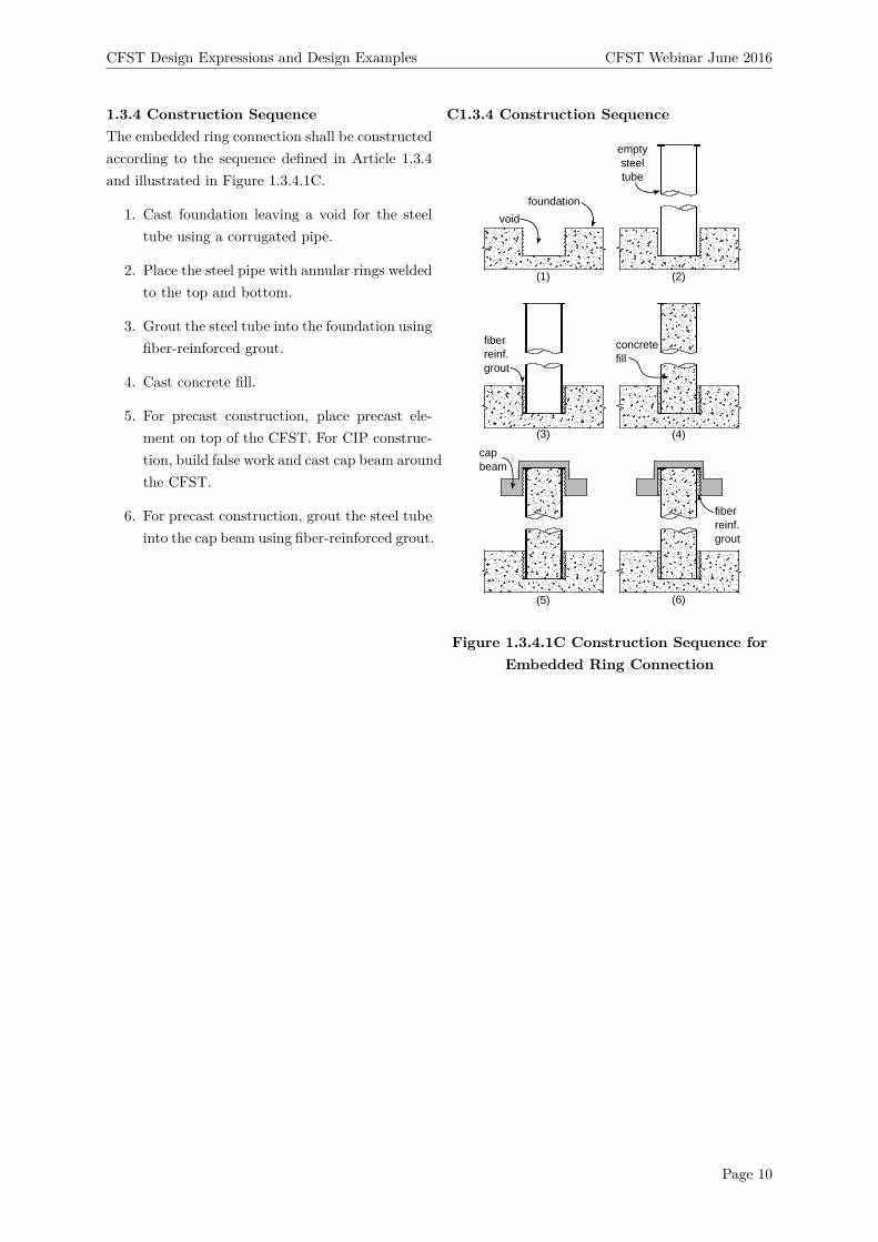
1.3.4 Construction SequenceThe embedded ring connection shall be constructedaccording to the sequence defined in Article 1.3.4and illustrated in Figure 1.3.4.1C.
1. Cast foundation leaving a void for the steeltube using a corrugated pipe.
2. Place the steel pipe with annular rings weldedto the top and bottom.
3. Grout the steel tube into the foundation usingfiber-reinforced grout.
4. Cast concrete fill.
5. For precast construction, place precast ele-ment on top of the CFST. For CIP construc-tion, build false work and cast cap beam aroundthe CFST.
6. For precast construction, grout the steel tubeinto the cap beam using fiber-reinforced grout.
C1.3.4 Construction Sequence
(1)
void
foundation
emptysteeltube
fiberreinf.grout
concretefill
(2)
(3) (4)
(5) (6)
capbeam
fiberreinf.grout
Figure 1.3.4.1C Construction Sequence forEmbedded Ring Connection
Page 10
CFST Design Expressions and Design Examples CFST Webinar June 2016
1.4 Debonded Welded Dowel ConnectionDe-bonded welded dowel connections shall be de-signed according to requirements in Section 1.4.
corrugatedpipe*
void filledwith fiberreinforcedgrout*
capbeam
soffitfill
Le
annularring
Lpc
fill tube*CL transversehoopsdeck
CFSTcolumn
weldregion
Lw
24db
8t
Ls
Note: Cap beam reinforcing not shown. Deck reinforcing not shown.* Used for precast construction
venttube*
friction collar(duringconstruction)
gap betweenheads andtop of void(Le measuredfrom the bottomof this gap)
1.4.1 FlangeA flange shall be welded to the steel tube as illus-trated in Figure 1.4.1. The annular ring shall havethe same thickness of the steel tube with a yieldstress equal to or greater than that of the steel tube.The ring shall extend outside the tube 8 times thethickness of the tube as illustrated in Figure 1.4.1.The annular ring shall be welded to the steel tubeusing a fillet weld on the outside of the tube. Thefillet weld shall be the largest allowable based on thetube thickness as specified in AISC [2011]. Weldsshall provide a minimum CVN toughness of 40-ft-lbs at 70 degrees F.1.4.2 Dowel Embedment into CFST and CapBeam1.4.2.1 Dowel Embedment into Cap BeamLongitudinal column dowels shall extend into a voidin the cap beam. The embedment length shallbe the maximum length calculated using Equation1.4.2.1.1 where ψe is the reinforcing bar coating fac-tor defined in ACI 318 (1.0 for uncoated bars, and1.2 for epoxy coated bars), Ldb is the debondedlength of the reinforcing bar as defined in Article1.4.4.2, f ′c,cap is the compressive strength of thecap beam in psi, and fy,b is the yield capacity ofthe longitudinal dowel in psi.
C1.4 Debonded Welded Dowel ConnectionThe debonded welded bar connection utilizes a ringof headed reinforcing bars which are welded intothe tube and developed into the cap beam. Thestrength and ductility of this connection type iscontrolled by the reinforcing ratio of the longitu-dinal reinforcing which extends from the columninto the cap beam. The welded detail is primarilyintended to decrease the development length andutilize the maximum moment arm within the CFSTcolumn.
C1.4.1 FlangeThe annular ring is welded to the steel tube to pro-vide a larger area to transfer compressive stressfrom the steel tube to the cap beam. This helpslimit localized grout crushing. The fillet weld isdesigned to transfer to compressive stress from thetube into the annular ring.
C1.4.2.1 Dowel Embedment into Cap BeamThe headed reinforcing must extend into the capbeam for a length sufficient to fully develop thereinforcing bar while eliminating the potential fora conical pullout failure as illustrated in FigureC1.4.2.1.1. Equation 1.4.2.1.1a defines the requireddevelopment length as specified in Article 12.6 ofACI 318 [ACI, 2011], while Equation 1.4.2.1.1b de-fines the required embedment depth to eliminateconical pullout failure as determined using the trans-fer mechanism shown in Figure C1.4.2.1.1. The em-
Page 11
CFST Design Expressions and Design Examples CFST Webinar June 2016
Le ≥ 0.016∗ψ∗Fy,b√f ′
g
(f ′g in psi) Equation 1.4.2.1a
Le ≥√
D2
4 + 1.2Fy,bAst,b
6π√f ′
c,cap
−D/2 (f ′c,cap in psi) Equa-
tion 1.4.2.1b
Le ≥ 3db + 0.5Ldb Equation 1.4.2.1c
1.4.2.2 Dowel Embedment into CFST Col-umnLongitudinal reinforcing shall extend a distance 24dbinto the CFST column.
1.4.3 Dowel-to-Steel Tube WeldsReinforcing bars shall be welded to the inside ofthe steel tube using flare bevel groove welds onboth sides of the reinforcing bars as shown in Fig-ure C1.4.3.1. The minimum length of the welds,Lw, shall be the maximum length calculated usingEquation 1.4.3.1. All material strengths (Fy,bar andFEXX) are in ksi.
Lw = 5.6AbFy,b
FEXXdbEquation 1.4.3.1a
Lw = 0.83AbFy,b
Fy,sttEquation 1.4.3.1b
Lw = 1.11AbFy,b
Fu,sttEquation 1.4.3.1c
bedment depth requirement in Equation 1.4.2.1chas been included to ensure a minimum bondedlength of 3db is included adjacent to the head onthe end of the headed dowel as illustrated in Fig-ure 1.4.1. This region of bonded reinforcing mustbe included to ensure adequate anchorage of thelongitudinal reinforcing into the cap beam.
bottom ofcap beam
Mu
VuAstFu
Pu
Le
top of deck
compressionstrut
shearstirrups
corrugatedpipe (ifapplicable)
Figure C1.4.2.1.1 Dowel TransferMechanism
C1.4.2.2 Dowel Embedment into CFST Col-umnThe required reinforcing embedment into the CFSTcolumn specified in Article 1.4.2.2 is based on re-search conducted on the pullout strength of rein-forcing welded into CFSTs. Results suggest thatthe embedment can be decreased to as low as 16db,however 24db is required to provide a reasonablefactor of safety.C1.4.3 Dowel-to-Steel Tube WeldsThe weld lengths specified in Article 1.4.3 are cal-culated to develop the yield capacity of the reinforc-ing bars based on typical weld limit states for flarebevel groove welds. These equations are based onwelding requirements for reinforcing bars specifiedin AWS 1.4, which defines the effective throat widthto be 0.2db as illustrated in Figure C1.4.3.1. Equa-tion 1.4.3.1a is based on failure of the weld metal,Equation 1.4.3.1b is based on yielding of the tubesteel, and Equation 1.4.3.1c is based on rupture ofthe tube steel. Strength reduction factors specifiedaccording to the AISC Construction Manual havebeen included in Equation 1.4.3.1.
Page 12
CFST Design Expressions and Design Examples CFST Webinar June 2016
1.4.4 Debonded DowelsLongitudinal column dowels shall be de-bonded fromthe surrounding concrete in the connection regionaccording to the requirements in Section 1.4.4. Thede-bonded region is denoted as Ldb in Figure 1.4.4.1.
Note: Cap beam not shown
bottom ofcap beam
de-bondedregion
CL
CFSTcolumn
1/2Ldb
1/2Ldb
min3db
top of deck
Figure 1.4.4.1 WD Debonding Details
1.4.4.1 Debonding MethodsThe Engineer shall specify the de-bonding methodon project plans on a project by project basis.
1.4.4.1 Debonded LengthLongitudinal reinforcing shall be de-bonded from
Lw
tw=0.2db
weld
reinforcingdowel
steeltube
steeltube
reinforcingdowel
Figure C1.4.3.1 Flare Bevel Groove Weld
C1.4.4 Debonded DowelsLongitudinal reinforcing is de-bonded in the con-nection region with the intention of evenly distribut-ing strain across the de-bonded length, thereby in-creasing the ductility of the connection.
C1.4.4.1 Debonding MethodsSeveral de-bonding methods have been evaluatedin previous research including encasing the bars intight-fitting PVC pipe, or wrapping the bars withduct tape. Other methods may be considered solong as it has been shown that they adequately de-bond the reinforcing from the surrounding concrete.
Page 13
CFST Design Expressions and Design Examples CFST Webinar June 2016
the surrounding concrete in the connection regionas illustrated in Figure 1.4.4.1. The de-bondedlength, Ldb, shall be calculated according to Equa-tion 1.4.4.2.1 or Equation 1.4.4.2.2 where θ is thetarget rotation for reinforcing bar fracture, and φsis the curvature of the connection at a steel strainlimit of 0.7εu as obtained from a moment curvatureanalysis. Half of the de-bonded length shall ex-tend into the cap beam, and half of the de-bondedlength shall extend through the soffit fill and intothe CFST column as illustrated in Figure 1.4.1.
Ldb = tanθ(D−t−db/2)0.7εu
Equation 1.4.4.2.1
Ldb = θu
φuEquation 1.4.4.2.2
1.4.5 Transverse Column Reinforcing in JointRegionTransverse reinforcing shall be included in the jointregion in the form of spiral or discrete hoops asshown in Figure 1.4.1. The area and spacing ofthis reinforcing must conform to Equation 1.4.5.1.When discreet hoops are used, at least one hoopmust be placed in the depth of the soffit fill.1.4.6 Requirements for Bridge Layout andCap Beam Design1.4.6.1 Bridge LayoutThe column shall be laid out between the longitu-dinal girders.1.4.6.2 Cap Beam Reinforcing(A) Flexural ReinforcingLongitudinal flexural reinforcing shall be designedto resist 1.2Mp of the CFST column per require-ments in the Caltrans SDC V. 1.7 [Caltrans, 2010].Longitudinal flexural reinforcing shall be spaced uni-formly across the width of the cap beam. Somelongitudinal reinforcing in the bottom layer will beinterrupted by the embedded corrugated pipe. Thebottom layer of flexural reinforcing not interruptedby the corrugate pipe shall be designed to resist1.2Mp of the CFST column. Interrupted bars shallstill be included as shown in Figure 1.3.3.(B) Vertical StirrupsVertical stirrups shall be included according to re-quirements in Article 7.4.4.2 in the Caltrans SDC[Caltrans, 2010].
C1.4.5 Transverse Column Reinforcing in JointRegionTransverse reinforcing is placed around the rein-forcing bars to increase confinement in the joint re-gion especially through the depth of the soffit fill.
Page 14
CFST Design Expressions and Design Examples CFST Webinar June 2016
(C) Horizontal StirrupsHorizontal stirrups shall be included according torequirements in Article 7.4.4.2 in the Caltrans SDC[Caltrans, 2010].1.4.6.3 Soffit Fill DepthThe soffit fill depth, Ls, shall be calculated accord-ing to Equation 1.4.6.1.1.
Ls ≥ sin (θu)(D2 + 8t
)Equation 1.4.6.3.1
1.4.6.4 Requirements for Headed Reinforc-ingMinimum cover shall be provided when headed re-inforcing is anchored in the cap beam according torequirements in Article 1.4.6.4. These requirementsare summarized in Figure 1.4.6.4.1.1. The thickness of side cover around the headmust be equal to or greater than the diameter ofthe head.2. A minimum depth of 3dh shall be included abovethe heads in the headed reinforcing where dh is thediameter of the head.3. Nominal amounts of longitudinal reinforcing (e.g.reinforcing steel in the plane orthogonal to the headedreinforcement) shall be placed above the head.
Elevation
Plan
ring ofheadedbars
capbeam
longitudinalreinforcingbeyond head
ring ofheadedbars
column
dh
min 3dh
min dh
where:dh = diameter of headfy < 60-ksif'c < 6-ksi
Note: These requirements are applicable for Ah = 4Ab
C1.4.6.3 Soffit Fill DepthThe soffit fill depth requirement in Equation 1.4.6.1.1ensures that the annular ring does not come intocontact with the cap beam at the maximum ex-pected drift, θ.
C1.4.6.4 Requirements for Headed Reinforc-ingUnlike straight bar anchorage conditions, for whichthe deformations along the length of the bar provideprogressive anchorage, in a headed bar the headitself provides most of the anchorage. Under ten-sile loading the head reacts and transfers the forcethrough strutting action, as shown in Figure 1. Un-der compression, the headed bar transfers the forceto the concrete through strutting action towardsthe base. In both conditions, four aspects of dimen-sioning are important: (1) sufficient concrete depthto limit the shear stresses along the compressionstrut, (2) sufficient cover, (3) horizontal (longitudi-nal) reinforcement to resist the horizontal compo-nent of the strut and (4) vertical (transverse) re-inforcement to resist the vertical component of thestrut.
Page 15
CFST Design Expressions and Design Examples CFST Webinar June 2016
1.4.7 Construction SequenceThe welded dowel connection shall be constructedaccording to the sequence defined in Article 1.4.7and illustrated in Figure 1.4.7.1C.
1. Cast foundation leaving a void for the steeltube using a corrugated pipe.
2. Place the steel pipe with annular ring weldedto the bottom and longitudinal reinforcingand annular ring welded to the top.
3. Grout the steel tube into the foundation usingfiber-reinforced grout.
4. Cast concrete fill.
5. For precast construction, place precast ele-ment on top of the CFST with a friction col-lar. The headed reinforcing should not comeinto contact with the top of the void in thecap beam. For CIP construction, build falsework and cast cap beam around the CFST.
6. For precast construction, grout the welded re-inforcing into the void in the cap beam.
C1.4.7 Construction Sequence
(1) (2)
(3) (4)
(5) (6)
void
foundation
emptysteeltube
weldedheadedreinf.
transversehoops
fiberreinf.grout
concretefill
capbeam
fiberreinf.grout
frictioncollar
Figure 1.4.7.1C Construction Sequence forWelded Dowel Connection
Page 16
CFST Design Expressions and Design Examples CFST Webinar June 2016
1.5 Reinforced Concrete ConnectionReinforced concrete connections shall be designedaccording to requirements in Section 1.5.
void filledwith fiberreinforcedgrout*
capbeam
corrugatedpipe*
gap betweentube and cap beam (sameas Ls)
fill tube*
ring ofheadedbars
CL
transversespiral
venttube*deck
Note: Cap beam reinforcing not shown* Used for precast construction
Le
Ls
Lpc
Ld
transverse reinf.spaced equallyfrom bottem ofhead throughdevelopmentlength of barsin column
gap betweenheads andtop of void (Le
measured frombottom of thisgap)
frictioncollar(duringconstruction)
Figure 1.5.1 Reinforced ConcreteConnection
1.5.1 Dowel Embedment into Column andCap Beam1.5.1.1 Dowel Embedment into Cap BeamLongitudinal reinforcing shall extend into the capbeam as specified in Article 1.4.2.1.1.5.1.2 Dowel Embedment into CFST Col-umnLongitudinal reinforcing shall extend a distance Ldinto the CFST column according to Equation 1.5.2.2.1where ψe is the reinforcing bar coating factor asdefined in ACI 318 (1.0 for uncoated bars, and 1.2for epoxy coated bars), f ′c,fill, is the compressivestrength of the concrete fill in psi, and fy,b is theyield strength of the longitudinal dowels in psi.
Ld =(Fy,bψe
25√f ′
cf
)db Equation 1.5.1.1.1
1.5.2 Transverse ReinforcingTransverse reinforcing in the form of discrete hoopsor spiral shall extend from the cap beam and intothe column for a distance Ld as illustrated in Figure1.5.1.1.5.3 Requirements for Bridge Layout andCap Beam Design1.5.3.1 Bridge Layout
1.5 Reinforced Concrete ConnectionThe reinforced concrete connection consists of amore traditional reinforced concrete dowel connec-tion, as both transverse and longitudinal reinforc-ing extend from the CFST column into the capbeam. The strength and ductility of this connec-tion type is controlled by the reinforcing ratio andmoment arm of the longitudinal reinforcing. Notethat construction of this connection using precastsuper-structure components requires use of a fric-tion collar to temporarily support the cap beam.
C1.5.1.2 Dowel Embedment into CFST Col-umnThe headed reinforcing must extend into the CFSTcolumn for a length sufficient to fully develop thereinforcing bar. Equation 1.5.2.21 defines the re-quired development length as specified in Article12.2 of ACI 318 [ACI, 2011]. Equation 1.5.2.2.1 is asimplified development length equation which per-tains to geometries commonly found in reinforcedconcrete bridge columns. For uncommon geome-tries or reinforcing layouts, The Engineer shall ref-erence Article 12.2 of ACI 318 [ACI, 2011].
Page 17
CFST Design Expressions and Design Examples CFST Webinar June 2016
The column shall be laid out between the longitu-dinal girders.1.5.3.2 Cap Beam Reinforcing(A) Flexural ReinforcingLongitudinal flexural reinforcing shall be designedto resist 1.2Mp of the CFST column per require-ments in the Caltrans SDC V. 1.7 [Caltrans, 2010].Longitudinal flexural reinforcing shall be spaced uni-formly across the width of the cap beam. Somelongitudinal reinforcing in the bottom layer will beinterrupted by the embedded corrugated pipe. Thebottom layer of flexural reinforcing not interruptedby the corrugate pipe shall be designed to resist1.2Mp of the CFST column. Interrupted bars shallstill be included as shown in Figure 1.3.3.(B) Vertical StirrupsVertical stirrups shall be included according to re-quirements in Article 7.4.4.2 in the Caltrans SDCV. 1.7 [Caltrans, 2010].(C) Horizontal StirrupsHorizontal stirrups shall be included according torequirements in Article 7.4.4.2 in the Caltrans SDCV. 1.7 [Caltrans, 2010].1.5.4 Requirements for Headed ReinforcingCover for headed reinforcing shall be included ac-cording to requirements in Article 1.4.6.2.1.5.5 Construction SequenceThe reinforced concrete connection shall be con-structed according to the sequence defined in Arti-cle 1.5.5 and illustrated in Figure 1.5.5.1C.
1. Cast foundation leaving a void for the steeltube using a corrugated pipe.
2. Place the steel pipe with an annular ring weldedto the bottom.
3. Grout the steel tube into the foundation usingfiber-reinforced grout.
4. Temporarily support longitudinal reinforcingcage at the top of the column, and cast con-crete fill.
5. For precast construction, place precast ele-ment on top of the CFST using a friction col-lar. The headed reinforcing should not comeinto contact with the top of the void in thecap beam. For CIP construction, build falsework and cast cap beam around the CFST.
C1.5.5 Construction Sequence
Page 18
CFST Design Expressions and Design Examples CFST Webinar June 2016
6. For precast construction, grout the longitudi-nal reinforcing cage into the cap beam usingfiber-reinforced grout.
CFST Design Expressions and Design Examples CFST Webinar June 2016
3 ER Connection Design Example
A detailed design example is presented here to demonstrate the design of a CFST bridge column and ERconnection to facilitate implementation into seismic bridge design practice. The example is a redesign ofa conventional reinforced concrete bridge column and cap beam connection using the Laguna De SantaRosa Bridge (located outside of Santa Rosa, California) as a prototype structure (details illustrated inFig. 2). The design procedure is broken down into two primary components: (1) Design of the CFSTcomponent using recommendations in AASHTOa [2015], and (2) Design of the ER connection and capbeam using the recommendations presented herein. The design procedure is as follows.Design of CFST ComponentThe first step was to redesign the RC columns as CFST columns. The columns were designed using thefollowing procedure highlighted in the flow chart in Fig. 3. Note that the material properties used fordesign of the CFST columns are provided in Table 1.
Table 1: Nominal Material Properties for Design of CFST Columns
f ′c Ec Fy,st Fu,st Es
6-ksi 4415-ksi 50-ksi 60-ksi 29000-ksi
1. Determine Factored Loads (Pu,Mu, andVu)The following loads were provided by the California Department of Transportation.Service −→ Pu = 790− kip,Mu = 1920kip− ft, Vu = 256− kipControllingLimitStateLoad −→ Pu = 1300− kip,Mu = 5300kip− ft, Vu = 707− kip2. Size Initial CFST Column Based on Service Axial Load RangeThe initial section is designed to have an axial load in the range of 0.1Po − 0.2Po wherePo = πDtFy,st + 0.95(D2/4)πf ′cUsing a target D/t = 90 −→ t = 90/DSolving for D (with an assumed service load of 0.1Po):10(790/0.75) = 10(1053.33) = πD(D/90)50 + 0.95(D2/4)π6 −→ D = 41.145Try D = 44− in., t = 0.5− in.,D/t = 883. Calculate the Stiffness of the CFST ComponentThe effective stiffness is calculated using Equation 6.9.6.3.2-6 from AASHTOa [2015].EIeff = EsIst + C ′EcIc
CFST Design Expressions and Design Examples CFST Webinar June 2016
NOTE: Longitudinal deck reinforcing, diaphragm reinforcing, corbel reinforcing, and side reinforcing notshown.
CL762-mm(30")
559-mm(22")
508-mm(20")
#6 @ 152-mm (6")#6 @ 152-mm (6")
#6 @ 152-mm (6")
section B-B
CL
#6 tot. 4 rowswithin column
#6 tot. 4 rowswithin column
#6 tot. 4 rowswithin column
1067-mm (42")
203-mm (8")
#10 cont.tot. 12
#10 cont. bundledtot. 12 #10 cont.
tot. 14
section A-A
AB
B
Bent Cap Elevation
A
CC
section C-C
#8 @ 152-mm(6") hoop
#11 bundledtot. 32
1219-mm(48")
(a) Details of Prototype RC Structure
A
B
B
Bent Cap Elevation
CL
CL#10 cont. bundledtot. 12
#10 cont. bundledtot. 12 each side
#10 cont tot.10
#7 @ 6"
#7 @ 203-mm (8")
section A-A
#6 @ 203-mm (8")
#6 @ 203-mm (8")
851-mm (33.5")
203-mm (8")216-mm (8.5")
A
15-mm(0.625")
1118-mm(44")
13-mm(0.5")
Do = 1326-mm (52")Di = 884-mm (25")
Annular Ring Details
#6 @ 152-mm (6")
1372-mm (54")corrugated pipe
762-mm(30")
559-mm(22")
steeltube
508-mm(20")
section B-B
annularring
(b) Details of ER CFST Connection
Flange and Dowel Debonding Details
debondedregion in
667-mm(26.25")
Lw = 159-mm(6.25")
CL
#10 cont. bundledtot. 12
#10 cont. bundledtot. 12 each side
#10 cont tot.10
#6 @ 152-mm(6")
#6 @ 152-mm (6")
section A-A
#6 @ 152-mm (6")
#6 @ 152-mm (6")
851-mm (33.5")
203-mm (8")216-mm (8.5")
A
B
B
Bent Cap Elevation
A Do = 1326-mm (52")Di = 1118-mm (44")
#6 @ 152-mm (6")
1219-mm (48")corrugated pipe
762-mm(30")
559-mm(22")
508-mm(20")
section B-B
ring of 32 headed#11 dowels
bottom ofcap beam
flange
XX"
51-mm (2") soffitfill
13-mm(0.5")
13-mm(0.5")
CL
#9 hoops@ 76-mm(3")
667-mm(26.25")
1118-mm(44-in.)
(c) Details of WD CFST Connection
Figure 2: Details of RC Prototype Structure and Redesigned CFST Structure with ER Connection
Page 21
CFST Design Expressions and Design Examples CFST Webinar June 2016
Determine Factored Loads(Pu, Mu, Vu)
Size CFST Column(Based on Pu and D/t)
Calculate EffectiveStiffness of CFST
Magnify Mu
(Based on Stiffness)Compute the P-MInteraction Curve
Check Shear CapacityDetermine Mn, Pn, and Vn
Comibinations
START
FINISH
Select Final CFSTSize (Iterate if Nec.)
Figure 3: Flow Chart for Design of CFST Component
0 2 4 6 8 10
x 104
0
2000
4000
6000
8000
10000
12000
14000
Moment (kip−in)
Axi
al L
oad
(kip
)
serviceload
limit controllingstate load
CFST designinteraction curve CFST material
based interactioncurve
Figure 4: P-M Interaction Curve for CFST Component
The P-M interaction diagram was computed using the procedure specified in AASHTOa [2015]. First,the material based interaction surface was developed using the PSDM (as discussed in AASHTOa [2015]).Then, the influence of geometric nonlinearity was considered to develop the design interaction diagram.The interaction diagram and demands are illustrated in Fig. 4. The CFST component has adequatecapacity to sustain the combined loading combination, and the axial loads are in the range of 10% of thecrushing load.7. Calculate the Shear Strength of the CFST ComponentThe shear strength of the section is computed assuming that only the steel tube contributes to thestrength. The following shear strength expression has been adopted from the AISC steel constructionmanual [AISC, 2011]. The shear capacity of the CFST component is greater than the controlling limitstate shear demand.Vn = 0.6Fy,stAv−→ Av = 0.5Ast = 0.5× 68.72 = 34.36− in.2
Vn = 0.6× 50× 34.36 = 1031− kip > Vu/φ = 785− kip8. Select Final Size of CFST ComponentUse D=44-in., t=0.5-in., D/t=88Note that the final diameter of the CFST columns are less than that of the original RC columns, while,stiffness and strength of the CFSTs are greater than that of the original RC sections.Design of ER ConnectionDesign of the ER CFST column-to-cap beam connection is demonstrated in this section. The procedurefor designing this connection is summarized in the flow chart in Fig. 5. The final design, includingreinforcing steel details, is illustrated in Fig. 2. Note that a similar design process is used for an ERmoment resisting foundation connection. Note that the purpose of this example is to highlight the designrequirements specific to the ER connection. Therefore corbel reinforcing and side reinforcing, which areconsistent with requirements in [AASHTOa, 2015], are not included in the example.1. Size the Annular Ring
Page 22
CFST Design Expressions and Design Examples CFST Webinar June 2016
Size Annular Ring
Design Weld BetweenAnnular Ring and Tube
Calculate EmbedmentDepth, Le
Calculate PunchingShear Depth, Lpc
Size Depth and Widthof Cap Beam/Foundation
Size Depth of PrecastElements for Const. Loads
Capacity Design CapBeam/Foundation
FINISH
START
Figure 5: Flow Chart for Design of ER Connection
The annular ring is the same thickness and the same steel properties as the steel tube. The ring projectsinto and out of the tube for a distance of 8t, where t is the thickness of the steel tube. For the examplecolumn, the outer, Do, and inner, Di, diameters of the ring are calculated as:Do = D + 16t = 44 + 16× 0.5 = 52− in.Di = D − st− 16t = 44− 2× 0.5− 16× 13 = 25− in.Use an annular ring with Do = 52− in. and Di = 25− in.2. Design the Weld Between the Annular Ring and TubeThe weld between the steel tube and annular ring is calculated according to the specifications aboveassuming a weld metal strength of 70-ksi, which is greater than the yield strength of the tube.w ≥ 1.31Fu,stt
Fexx≥ 1.31×60×0.5
70 = 0.57− in.Use 0.625-in. fillet weldsNote: CJP welds can also be used.3. Calculate the Required Embedment DepthCalculate the required tube embedment depth into the cap beam.Le ≥
√D2
4 + DtFu
6√f ′
c,cap
− D2 =
√442
4 + 44×0.5×600006√
6000 − 442 = 33.5− in.
Use Le = 33.5− in.4. Calculate the Required Depth Above the Embedded Tube to Eliminate Punching ShearCalculate the required depth above the embedded tube. The required depth above the embedded tubeis calculated for two load cases; first to size the inverted-t, and second to determine the total requireddepth of the superstructure above the embedded to resist the controlling limit state load.For the purpose of sizing the inverted-t, the depth above the embedded tube is calculated to resistpunching shear failure during construction prior to grouting the connection. This calculation is madeaccording to ACI requirements for punching shear conservatively assuming one-way shear.Assumed construction dead load = 55-kip based on the as-built drawings of the precast components inthe prototype structure.φVc = φ0.17
√f ′cbod
−→ bo = π(Do + d) = π(52 + d)550000.75 = 2
√6000π(52 + d)d −→ d = 2.75− in.
Next, calculate the total required depth (deck and inverted-t) above the embedded CFST to eliminatethe potential for punching shear failure during seismic loading. Note that Cc and Cs are in kips.)
5. Size the Initial Depth of the Cap Beam Based on Steps 3 and 4The inverted-t requires a depth above the tube of 2.75-in. for construction loads, while the total requireddepth is 11.5-in. for seismic loading. Assuming a deck depth of around 8-in. this allows 3.5-in. of depthabove the embedded CFST in the inverted-T beam. Allowing additional space for reinforcing in the capbeam, a depth above the embedded CFST of 8.5-in. is selected.Use a total depth of Hcap = Le+ Lpc = 42− in. for the precast inverted-t.
Page 23
CFST Design Expressions and Design Examples CFST Webinar June 2016
The width of the stem in the inverted-T beam is selected based on the diameter of the corrugatedpipe (assuming modular construction method). The inner diameter of the corrugated pipe must exceedDo (which was calculated in Step 1). Galvanized corrugated pipe with an inner diameter of 54 in. iscommercially available. Thus the width of the stem of the inverted-T beam must exceed this diameterwith standard cover requirements.Use a stem width of 60-in.6. Capacity Design the Cap Beam to Resist 1.25Mp of the CFST ColumnThe plastic capacity of the CFST column is 1.25Mp,CFST = 85000kip − in.. A ledge width of 22-in. isassumed based on the dimensions of the prototype bridge. 20 No. 10 bars in the bottom of the inverted-t and 12 No. 10 bars in the top of the inverted-t are initially tried. Additional cap beam reinforcingconsisting of 14 No. 10 bars is included in the deck. The primary flexural reinforcing is arranged asshown in Fig. 2. The resulting flexural capacity of the cap beam are calculated as:M+n = 7199kip− ft
M−n = 7133kip− ftUse 20 No. 10 bars in the bottom of the inverted-t and 12 No. 10 bars in the top of theinverted-t. Include 14 No. 10 bars in the deck for additional negative moment capacity.7a. Design Vertical Stirrups in the Joint RegionThe required shear reinforcing in the joint region is calculated using the simplified expression Ajvs =0.65Ast in this document. This reinforcing must be evenly distributed in the hatched area described inthe specifications. The distribution of vertical shear reinforcing in the final design in this example isillustrated in Fig. 2.Ajvs = 0.65Ast = 0.65× 68.72Use 100 No. 6 vertical stirrup legs evenly distributed around the column −→ Ajvs = 44− in2
7b. Design Horizontal Stirrups in Joint RegionThe required area of horizontal stirrups is consistent with the requirements in the Caltrans SDC. Onelayer of horizontal stirrups must pass above the embedded CFST as shown in Fig. 2.Ajhs = 0.1Ast = 0.1× 0.1× 68.72 = 6.872− in.2
Use 3 rows of No. 7 hooks −→ Ajhs = 7.2− in.2
Page 24
CFST Design Expressions and Design Examples CFST Webinar June 2016
4 WD Connection Design Example
A detailed design example is presented here to demonstrate the design of a CFST bridge column and WDconnection to facilitate implementation into seismic bridge design practice. The example is a redesign ofa conventional reinforced concrete bridge column and cap beam connection using the Laguna De SantaRosa Bridge (located outside of Santa Rosa, California) as a prototype structure (details illustrated inFig. 2). The design procedure is broken down into two primary components: (1) Design of the CFSTcomponent and longitudinal dowels in the connection region using recommendations in AASHTOa [2015],and (2) Design of the WD connection and cap beam using the recommendations presented herein. Thedesign procedure is as follows.Design of CFST Component and Dowels in Connection RegionThe first step was to redesign the RC columns as CFST columns. The columns were designed usingthe procedure highlighted in the ER connection design example above. The final CFST column hadD = 44− in., t = 0.5− in.,D/t = 881. Design of CFST Dowels in the Connection RegionThe dowels in the connection region are designed to resist the applied loads. Based on the service andcontrolling limit state loads (provided in the previous example) assume 32 No. 11 dowels. Note that thedowel yield and rupture strengths are assumed to be 68-ksi and 98-ksi respectively.2. Check Crushing Capacity of CFST ConnectionCheck to ensure that the service axial load is approximately 10% of the crushing load of the WDconnection.Pu
79010800 = 0.07 ≤ 0.1 OK!3. Calculate the Effective Stiffness of the WD ConnectionEIeff = 4.09× 10⁸kip− in2 (from structural analysis program)4. Calculate the Moment Magnification Factorδs = 1/(1− Pu/(φPe))−→ Pe = π2EIeff/(KL)2 = π2 × 4.09× 108/(0.5× 15× 12)2 = 498354− kip)δs = 1/(1− 1300/(0.9× 498354)) = 15. Compute P-M Interaction Diagrams for CFST and WD ConnectionDevelopment of the P-M interaction curve for the CFST component is discussed in the previous example.The P-M interaction diagrams for the CFST and WD connection are plotted in Fig. 6. The interactioncurve for the WD connection was calculated using Caltrans requirements for RC columns [Caltrans,2010].Design WD ConnectionDesign of the WD CFST column-to-cap beam connection is demonstrated in this section. The procedurefor designing this connection is summarized in the flow chart in Fig. 7. The final design, includingreinforcing steel details, is illustrated in Fig. 2. Note that the purpose of this example is to highlight thedesign requirements specific to the WD connection. Therefore corbel reinforcing and side reinforcing,which are consistent with requirements in [AASHTOa, 2015], are not included in the example.1. Size FlangeDo = D + 16t = 44 + 16× 0.5 = 52− in.Use a flange with Do = 52− in..2. Design Weld Between Flange and Tubew ≥ 1.31Fu,stt
Fexx≥ 1.31×60×0.5
70 = 0.57− in.
Page 25
CFST Design Expressions and Design Examples CFST Webinar June 2016
0 2 4 6 8 10
x 104
0
2000
4000
6000
8000
10000
12000
14000
Moment (kip−in)A
xial
Loa
d (k
ip)
serviceload
limit controllingstate load
CFST designinteraction curve CFST material
based interactioncurve
Caltrans interactioncurve
Figure 6: P-M Interaction Curve for CFST Component and WD Connection
Size Flange
Design Weld BetweenFlange and Tube
Calculate EmbedmentDepth, Le
Calculate PunchingShear Depth, Lpc
Size Depth and Widthof Cap Beam/Foundation
Capacity Design CapBeam/Foundation
FINISH
STARTCalculate Length Dowel
Extends into CFST
Design Weld BetweenDowel and Tube
Design Column TransverseReinforcing
Calculate DebondedLength
Select LongitudinalDowels
Design Cap BeamVert. and Hor. Stirrups
Figure 7: Flow Chart for Design of WD Connection
Use 0.625-in. fillet welds3. Calculate Length Dowel Extends into CFSTThe dowels are required to extend into the steel tube for a distance of 24db.24db = 24× (11/8) = 33− in.Extend the dowels 33− in. into the steel tube.4. Design Weld Between Dowel and TubeThe required weld length is defined in the specifications above. Assume 70XX electrodes with a tensilestrength of 70-ksi.Lw = 5.6AbFy,b
FEXXdb= 5.6×1.56×68
70×1.375 = 6.17− in.Lw = 0.83AbFy,b
Fy,stt= 0.83×1.56×68
50×0.5 = 3.52− in.Lw = 1.11AbFy,b
Fu,stt= 1.11×1.56×68
70×0.5 = 3.36− in.Use a weld length Lw = 6.25− in.5. Calculate Dowel Debonded LengthThe debonded length is calculated assuming a target rotation demand of 8% and a steel ultimate strainof 0.09-in./in.Ldb = tanθ(D−t−db/2)
0.7εu= tan(0.08)(44−0.5−1.375/2)
0.7×0.09 = 54.5− in.Use a debonded length Ldb = 54.5− in.6. Calculate Dowel Embedment Depth into Cap BeamThe dowels are required to extend into the cap beam according to equations in the specifications above.Le ≥ 0.016∗ψ∗Fy,b√
f ′g
= 0.016×1.0×68000√6000 = 19.31− in.
Le ≥√
D2
4 + 1.2Fy,bAst,b
6π√f ′
c,cap
−D/2 =√
442
4 + 1.2×68000×49.926π√
6000 − 44/2 = 35.2− in.
Le ≥ 3db + 0.5Ldb = 3× 1.375 + 0.5× 54.5 = 31.375Extend the dowels for a distance Le = 35.25− in. into the cap beam.7. Calculate Required Punching Shear Depth Above the Headed Dowels
Page 26
CFST Design Expressions and Design Examples CFST Webinar June 2016
The required depth above the headed reinforcing to eliminate punching shear failure is defined in theproposed specifications.
Lpc ≥ 3dh = 3× 3.25 = 9.75− in
Use a depth of at least 9.75-in. above the top of the headed dowels
8. Size the Precast Inverted T
A total super structure depth of at least Le + Lpc is required. Assuming we have an 8-in. thick slab onthis bridge, a clear cover above the headed reinforcing of at least 1.75-in. is required in the inverted-t.Use a clear distance of 6.75-in. in the inverted-t in the interest of maintaining the same super-structuredepth as Example 1.
The depth of the inverted-t=6.75+35.25=42-in.
Use an inverted-t depth of 42-in.
The width of the stem in the inverted-T beam is selected based on the diameter of the corrugated pipe(assuming modular construction method). The inner diameter of the corrugated pipe must exceed thediameter of the CFST plus one dowel head diameter. Galvanized corrugated pipe with an inner diameterof 54 in. is commercially available. Thus the width of the stem of the inverted-T beam must exceed thisdiameter with standard cover requirements.
Use a stem width of 60-in.
9. Capacity Design the Cap Beam to Resist 1.2Mp,WDConnection
The plastic capacity of the WD connection is 1.2Mp,WDConnection = 79800kip − in.. A ledge width of22-in. is assumed based on the dimensions of the prototype bridge. 20 No. 10 bars in the bottom ofthe inverted-t and 12 No. 10 bars in the top of the inverted-t are initially tried. Additional cap beamreinforcing consisting of 14 No. 10 bars is included in the deck. The primary flexural reinforcing isarranged as shown in Fig. 2. The resulting flexural capacity of the cap beam are calculated as:
M+n = 86382kip− in
M−n = 85593kip− in
Use 20 No. 10 bars in the bottom of the inverted-t and 12 No. 10 bars in the top of theinverted-t. Include 14 No. 10 bars in the deck for additional negative moment capacity.
10a. Design Vertical Stirrups in the Joint Region
The required shear reinforcing in the joint region is calculated using Equation 7.19 in Caltrans [2010].
Ajvs = 0.2Ast,b = 0.5× 49.92 = 10− in.2
Use No. 6 vertical stirrups arranged as shown in Fig. 2.
10b. Design Horizontal Stirrups in the Joint Region
The required area of horizontal stirrups is consistent with the requirements in the Caltrans SDC [Caltrans,2010]. One layer of horizontal stirrups must pass above the corrugated metal duct as illustrated in Fig. 2.
Ajhs = 0.1Ast = 0.1× 49.92 = 5− in.2
Use 3 rows of No. 6 hooks as shown in Fig. 2.
11. Design Transverse Column Reinforcing which Extends into the Cap Beam
The required transverse reinforcing ratio which extends into the joint region is defined in Equation 7.23of Caltrans [2010].
ρs = 0.4Ast,b
L2e
= 0.4 49.9235.252 = 0.016
Try No. 9 hoops at 3-in. c-c −→ ρs = 0.016
Use No. 9 hoops at 3-in. c-c.
Page 27
CFST Design Expressions and Design Examples CFST Webinar June 2016
References
AASHTOa (2015). AASHTO LRFD Bridge Design Specification. American Association of State Highwayand Transportation Official, Washington, DC.
ACI (2011). Building Code Requirements for Structural Concrete. American Concrete Institute, Farm-ington Hills, MI.
AISC (2011). Steel Construction Manual. American Institute of Steel Construction, Chicago, IL, 14edition.
Caltrans (2010). Caltrans Seismic Design Criteria. California Department of Transportation, Sacra-mento, CA.
Lehman, D. and Roeder, C. (2012a). Foundation connection for circular concrete filled tubes. Journalof Constructional Steel Research, 78:212–225.
Lehman, D. and Roeder, C. (2012b). Rapid construction of bridge piers with improved seismic per-formance: An initial study in the use of concrete filled steel tubes for bridge piers and foundationconnections. Technical Report CA12-1972, California Department of Transportation.
Montejo, L., Kowalsky, M., and Hassan, T. (2009). Seismic behavior of flexural dominated reinforedconcrete bridge columns at low temperatures. Journal of Cold Regions Engineering, 23:18–42.
Restrepo, J., Tobolski, M., and Matsumoto, E. (2011). Development of a Precast Bent Cap System forSeismic Regions. Technical Report 681, NCHRP.
Stephens, M., Lehman, D., and Roeder, C. (2015). Concrete filled tube bridge pier connections for accel-erated bridge construction. Technical Report CA15-2417, California Department of Transportation.