27
1 CM Technology US-RUPS Product Line Introduction
| Date post: | 24-Dec-2015 |
| Category: |
Documents |
| Upload: | jacob-moody |
| View: | 219 times |
| Download: | 5 times |

1
CM TechnologyUS-RUPS Product Line Introduction
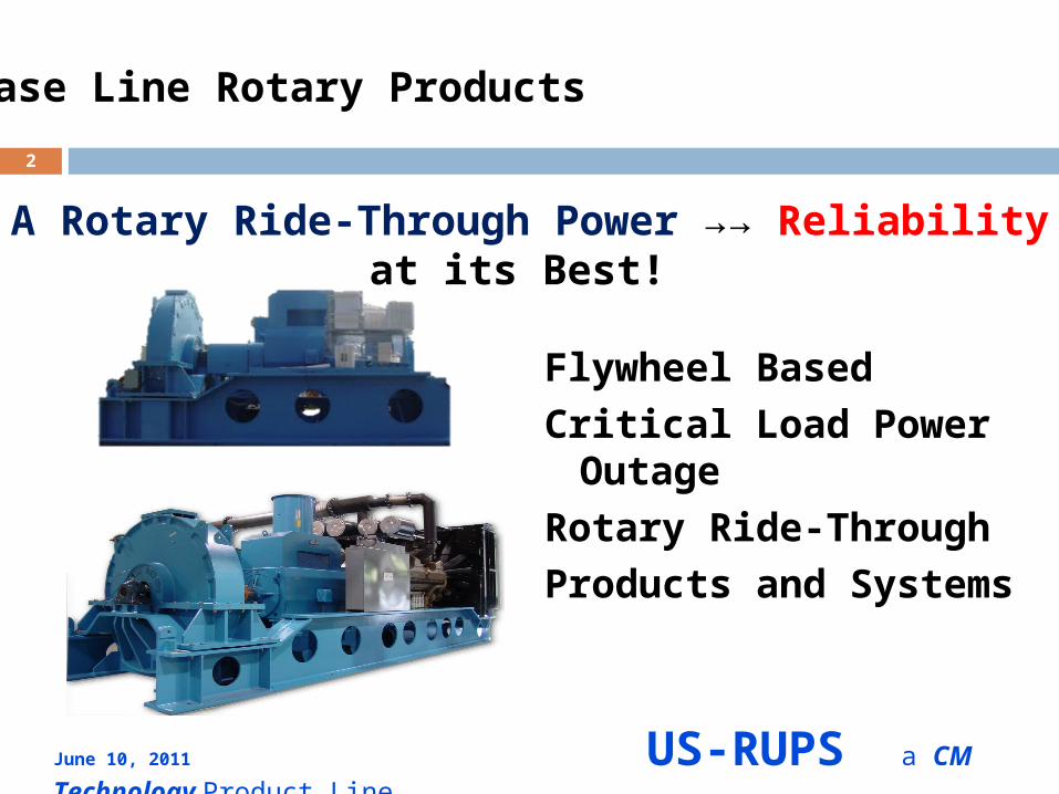
Flywheel BasedCritical Load Power Outage Rotary Ride-Through Products and Systems
2
A Rotary Ride-Through Power →→ Reliability at its Best!
Base Line Rotary Products
June 10, 2011 US-RUPS a CM Technology Product Line
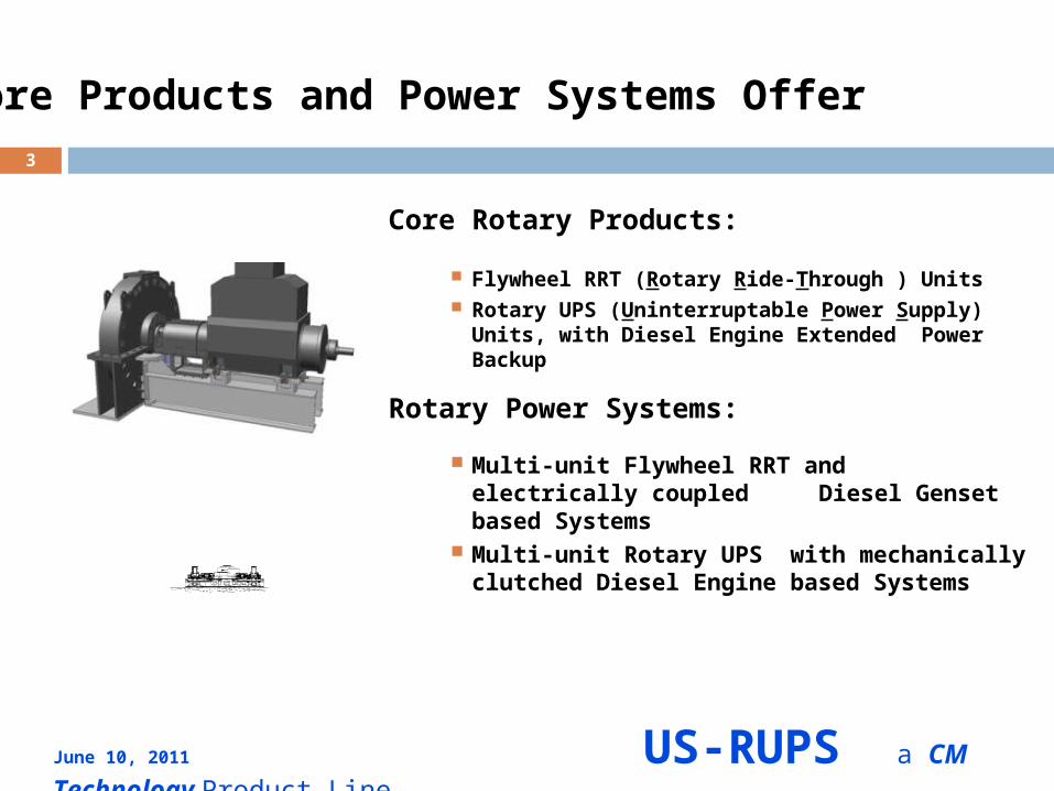
Core Rotary Products:
Flywheel RRT (Rotary Ride-Through ) Units Rotary UPS (Uninterruptable Power Supply) Units, with
Diesel Engine Extended Power Backup
Rotary Power Systems:
Multi-unit Flywheel RRT and electrically coupled Diesel Genset based Systems
Multi-unit Rotary UPS with mechanically clutched Diesel Engine based Systems
3
Core Products and Power Systems Offer
June 10, 2011 US-RUPS a CM Technology Product Line
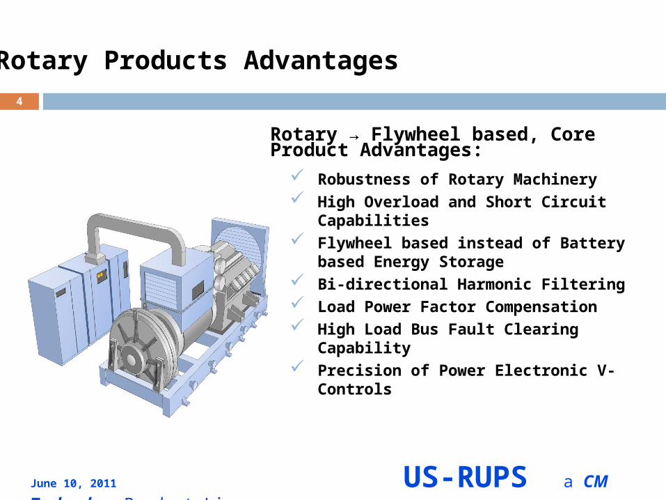
Rotary → Flywheel based, Core Product Advantages:
Robustness of Rotary Machinery High Overload and Short Circuit Capabilities Flywheel based instead of Battery based
Energy Storage Bi-directional Harmonic Filtering Load Power Factor Compensation High Load Bus Fault Clearing Capability Precision of Power Electronic V-Controls
4
Rotary Products Advantages
June 10, 2011 US-RUPS a CM Technology Product Line
5
Rotary Products User Benefits
Critical Load Service Reliability Protection Benefits:
1. High Reliability, UPS Grade Power Source Fewer components and no low-reliability
battery required
2. Low Operating and Maintenance (O&M) Costs High efficiency, no A/C system required Near unity power factor, no VAR penalty costs
3. Ease to Install & Long Service Life Robust and simple construction 25-year service life, low life-cycle costs
June 10, 2011 US-RUPS a CM Technology Product Line
6
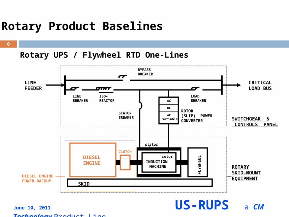
Rotary Product Baselines
Rotary UPS / Flywheel RTD One-Lines
AC
AC Variable
DC
DIESELENGINE
FLY
WH
EEL
SKID
CLUTCH
stator
rotorINDUCTION MACHINE
LINEFEEDER ISO-
REACTOR
STATORBREAKER
LINEBREAKER
LOADBREAKER
BYPASSBREAKER
CRITICALLOAD BUS
ROTOR (SLIP) POWERCONVERTER
SWITCHGEAR & CONTROLS PANEL
ROTARYSKID-MOUNTEQUIPMENTDIESEL ENGINE
POWER BACKUP
June 10, 2011 US-RUPS a CM Technology Product Line
7
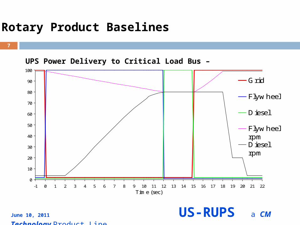
Rotary Product Baselines
UPS Power Delivery to Critical Load Bus – Principle Explained
0
10
20
30
40
50
60
70
80
90
100
-1 0 1 2 3 4 5 6 7 8 9 10 11 12 13 14 15 16 17 18 19 20 21 22
Time (sec)
Grid
Flywheel
Diesel
FlywheelrpmDieselrpm
June 10, 2011 US-RUPS a CM Technology Product Line
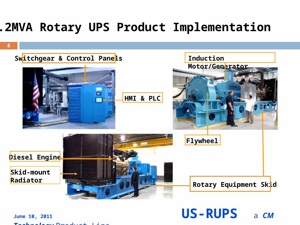
8
2.2MVA Rotary UPS Product Implementation
Switchgear & Control Panels
HMI & PLC
Induction Motor/Generator
Flywheel
Diesel Engine
Skid-mount Radiator
Rotary Equipment Skid
June 10, 2011 US-RUPS a CM Technology Product Line
9
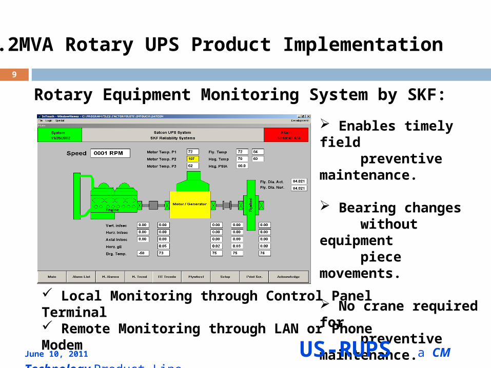
2.2MVA Rotary UPS Product Implementation
Rotary Equipment Monitoring System by SKF:
Local Monitoring through Control Panel Terminal Remote Monitoring through LAN or Phone Modem
Enables timely field preventive maintenance.
Bearing changes without equipment piece movements.
No crane required for preventive maintenance.
June 10, 2011 US-RUPS a CM Technology Product Line
10
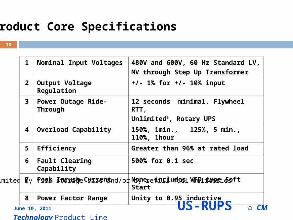
Product Core Specifications
1 Nominal Input Voltages 480V and 600V, 60 Hz Standard LV,MV through Step Up Transformer
2 Output Voltage Regulation +/- 1% for +/- 10% input
3 Power Outage Ride-Through 12 seconds minimal. Flywheel RTT, Unlimited1, Rotary UPS
4 Overload Capability 150%, 1min., 125%, 5 min., 110%, 1hour
5 Efficiency Greater than 96% at rated load
6 Fault Clearing Capability 500% for 0.1 sec
7 Peak Inrush Current None, includes VFD type Soft Start
8 Power Factor Range Unity to 0.95 inductive
1. Limited by fuel storage size and/or by refill fuel deliveries
June 10, 2011 US-RUPS a CM Technology Product Line
11
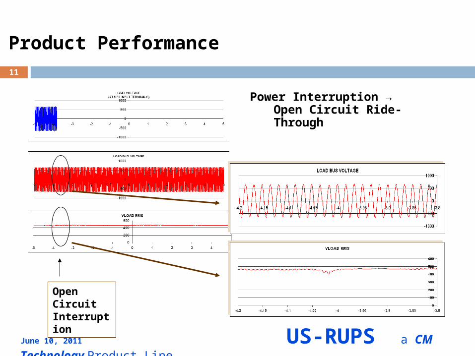
Product Performance
Power Interruption →Open Circuit Ride-Through
Engine
Open Circuit Interruption
June 10, 2011 US-RUPS a CM Technology Product Line
12
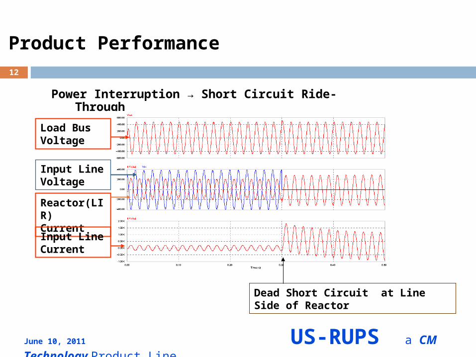
Product Performance
Power Interruption → Short Circuit Ride-Through
Load BusVoltage
Input LineVoltage
Reactor(LIR) Current
Input LineCurrent
Dead Short Circuit at Line Side of Reactor
June 10, 2011 US-RUPS a CM Technology Product Line
13
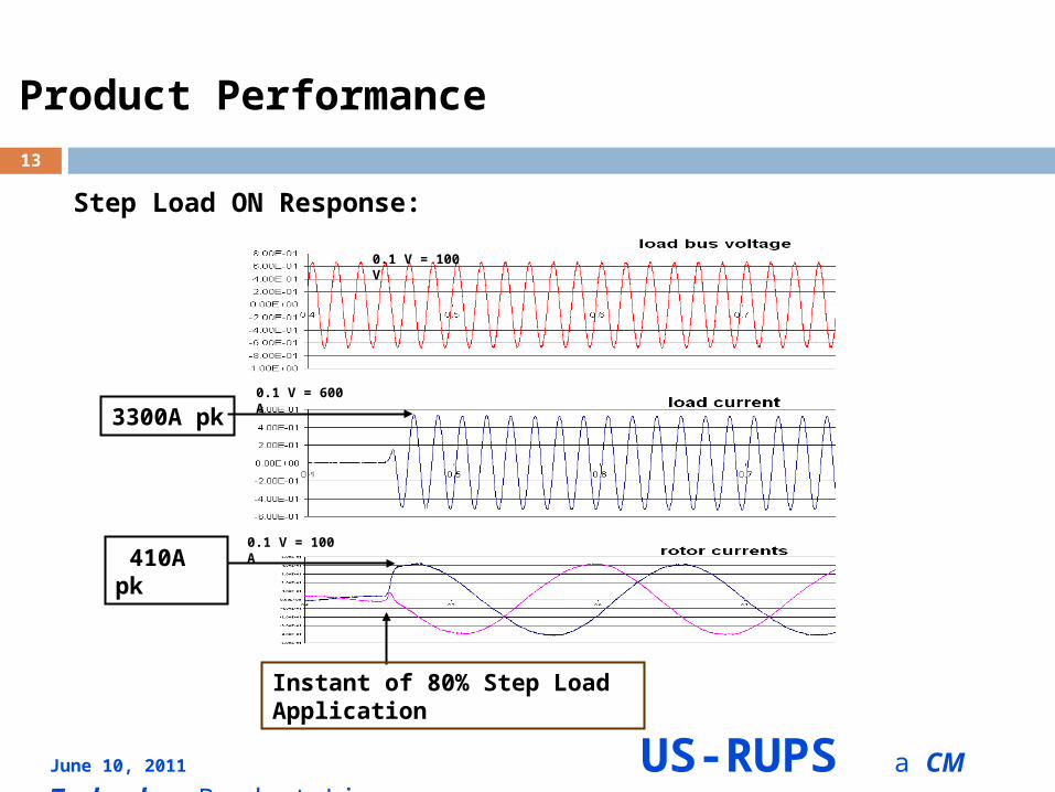
Product Performance
Step Load ON Response:
0.1 V = 100 A
0.1 V = 600 A
0.1 V = 100 V
3300A pk
410A pk
Instant of 80% Step Load Application
June 10, 2011 US-RUPS a CM Technology Product Line
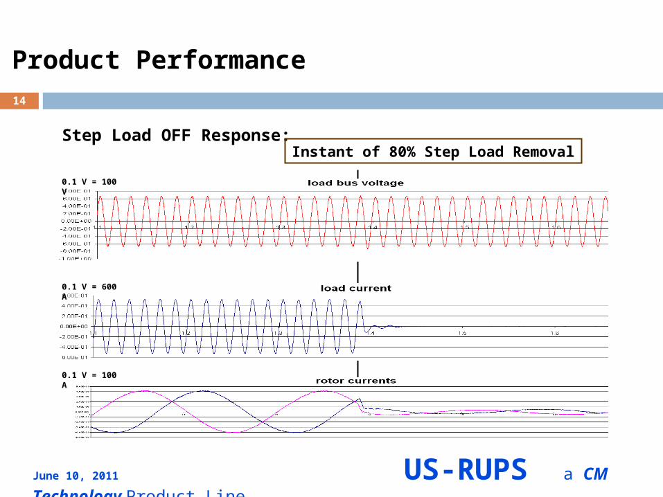
14
Product Performance
Step Load OFF Response:Instant of 80% Step Load Removal
0.1 V = 100 V
0.1 V = 600 A
0.1 V = 100 A
June 10, 2011 US-RUPS a CM Technology Product Line
15
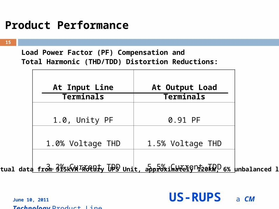
Product Performance
Load Power Factor (PF) Compensation and Total Harmonic (THD/TDD) Distortion Reductions:
At Input Line Terminals At Output Load Terminals
1.0, Unity PF 0.91 PF
1.0% Voltage THD 1.5% Voltage THD
3.2% Current TDD 5.5% Current TDD
Actual data from 315kVA Rotary UPS Unit, approximately 120kW, 6% unbalanced load.
June 10, 2011 US-RUPS a CM Technology Product Line
16
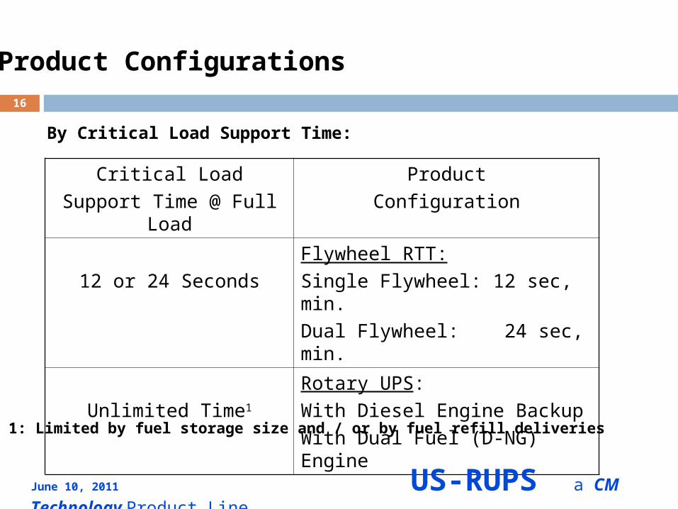
Product Configurations
By Critical Load Support Time:
Critical Load
Support Time @ Full Load
Product
Configuration
12 or 24 Seconds
Flywheel RTT:
Single Flywheel: 12 sec, min.
Dual Flywheel: 24 sec, min.
Unlimited Time1
Rotary UPS:
With Diesel Engine Backup
With Dual Fuel (D-NG) Engine
Note 1: Limited by fuel storage size and / or by fuel refill deliveries
June 10, 2011 US-RUPS a CM Technology Product Line
17
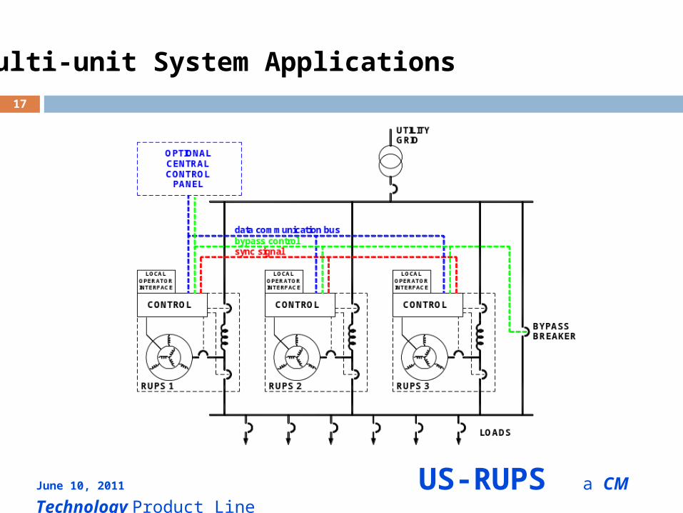
Multi-unit System Applications
June 10, 2011 US-RUPS a CM Technology Product Line
18
Multi-unit System Applications
The excitation frequency/phase of the IMG is determined by high-speedelectronic control.
Load frequency/phase is not influenced by rotor speed/position.
Multiple IMGs can be perfectly synchronized with precise electronic frequency control.
Machine speed differences do not cause circulation of real power.
Load steps have no effect on frequency.
Induction Machine Generator (IMG) Provides Important AdvantagesOver Synchronous Machines in Multiple-Unit System Configurations
June 10, 2011 US-RUPS a CM Technology Product Line
19
Multi-unit System Applications
Control Modes:Connected to utility grid
Tie-inductors of all Rotary units are in parallel between grid bus and load bus. Power from the grid is shared as a result of the (equal) tie inductors. IMGs regulate load bus voltage level by providing fast reactive power. IMGs share reactive power through a voltage droop algorithm. IMGs provide transient real power for sudden load steps. Real power for each IMG may be different. Real power for each unit is limited by the internal control.
Disconnected from the utility grid• Electronic synchronization signal keeps the excitation of all IMGs precisely locked in phase (and frequency).• Leakage reactance of the IMGs ensures real power sharing.• IMGs regulate load bus voltage level by providing fast reactive power.• IMGs share reactive power through a voltage droop algorithm.
June 10, 2011 US-RUPS a CM Technology Product Line
20
Multi-unit System Applications
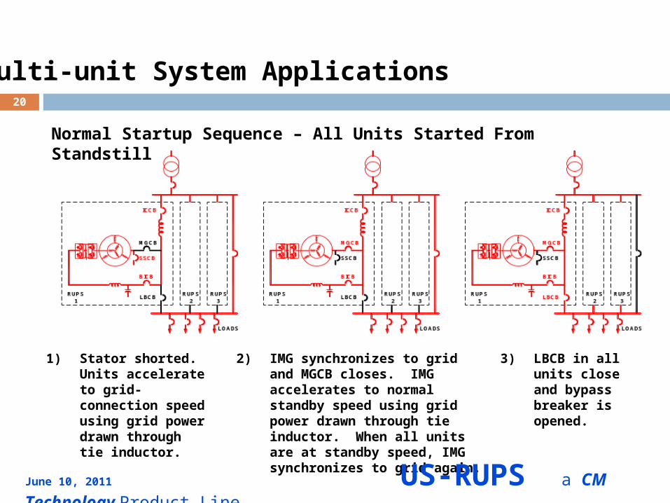
1) Stator shorted. Units accelerate to grid-connection speed using grid power drawn through tie inductor.
2) IMG synchronizes to grid and MGCB closes. IMG accelerates to normal standby speed using grid power drawn through tie inductor. When all units are at standby speed, IMG synchronizes to grid again.
3) LBCB in all units close and bypass breaker is opened.
Normal Startup Sequence – All Units Started From Standstill
June 10, 2011 US-RUPS a CM Technology Product Line
21
Multi-unit System Applications
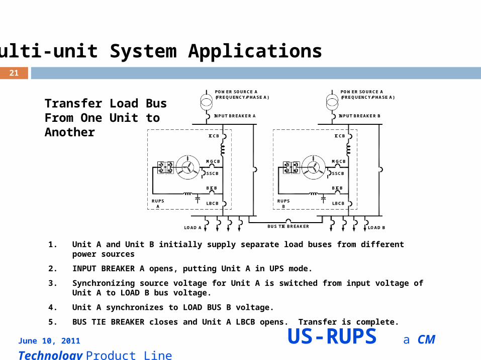
1. Unit A and Unit B initially supply separate load buses from different power sources
2. INPUT BREAKER A opens, putting Unit A in UPS mode.
3. Synchronizing source voltage for Unit A is switched from input voltage of Unit A to LOAD B bus voltage.
4. Unit A synchronizes to LOAD BUS B voltage.
5. BUS TIE BREAKER closes and Unit A LBCB opens. Transfer is complete.
Transfer Load BusFrom One Unit toAnother
June 10, 2011 US-RUPS a CM Technology Product Line

22
Multi-unit System Applications
1. Unit A initially connected to POWER SOURCE A.
2. INPUT BREAKER A opens, putting Unit A in UPS mode (ICCB open).
3. INPUT BREAKER B closes.
4. Unit A synchronizes to POWER SOURCE B voltage.
5. ICCB closes. Transfer is complete.
Transfer of Unitfrom One PowerSource to Another
June 10, 2011 US-RUPS a CM Technology Product Line
23
System Reliability and Availability
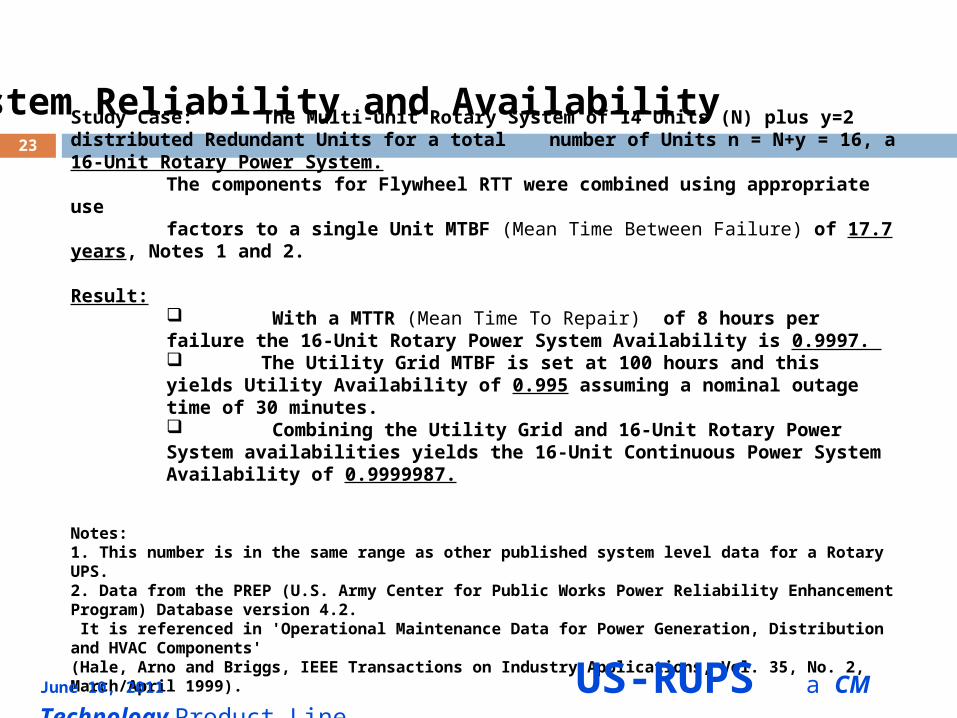
Study Case: The Multi-unit Rotary System of 14 Units (N) plus y=2 distributed Redundant Units for a total number of Units n = N+y = 16, a 16-Unit Rotary Power System.The components for Flywheel RTT were combined using appropriate use factors to a single Unit MTBF (Mean Time Between Failure) of 17.7 years, Notes 1 and 2.
Result: With a MTTR (Mean Time To Repair) of 8 hours per failure the 16-Unit Rotary Power System Availability is 0.9997. The Utility Grid MTBF is set at 100 hours and this yields Utility Availability of 0.995 assuming a nominal outage time of 30 minutes. Combining the Utility Grid and 16-Unit Rotary Power System availabilities yields the 16-Unit Continuous Power System Availability of 0.9999987.
Notes:1. This number is in the same range as other published system level data for a Rotary UPS.2. Data from the PREP (U.S. Army Center for Public Works Power Reliability Enhancement Program) Database version 4.2. It is referenced in 'Operational Maintenance Data for Power Generation, Distribution and HVAC Components' (Hale, Arno and Briggs, IEEE Transactions on Industry Applications, Vol. 35, No. 2, March/April 1999).
June 10, 2011 US-RUPS a CM Technology Product Line
24
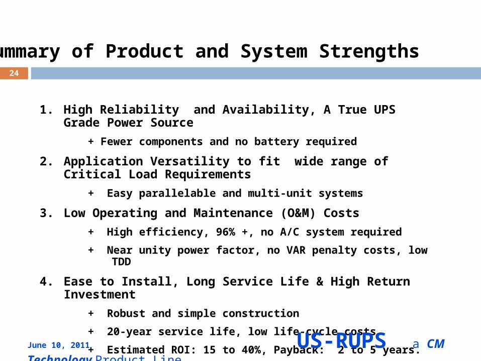
Summary of Product and System Strengths
1. High Reliability and Availability, A True UPS Grade Power Source
+ Fewer components and no battery required
2. Application Versatility to fit wide range of Critical Load Requirements
+ Easy parallelable and multi-unit systems
3. Low Operating and Maintenance (O&M) Costs
+ High efficiency, 96% +, no A/C system required
+ Near unity power factor, no VAR penalty costs, low TDD
4. Ease to Install, Long Service Life & High Return Investment
+ Robust and simple construction
+ 20-year service life, low life-cycle costs
+ Estimated ROI: 15 to 40%, Payback: 2 to 5 years.
June 10, 2011 US-RUPS a CM Technology Product Line
25
June 10, 2011 US-RUPS a CM Technology Product Line
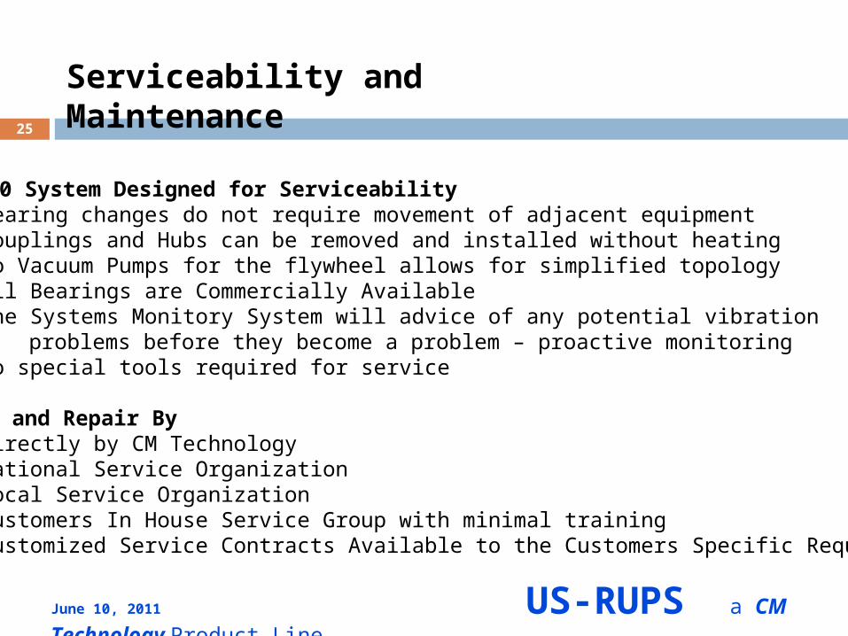
Serviceability and Maintenance
RRT 2200 System Designed for Serviceability• Bearing changes do not require movement of adjacent equipment• Couplings and Hubs can be removed and installed without heating• No Vacuum Pumps for the flywheel allows for simplified topology• All Bearings are Commercially Available• The Systems Monitory System will advice of any potential vibration problems before they become a problem – proactive monitoring• No special tools required for service
Service and Repair By• Directly by CM Technology• National Service Organization• Local Service Organization• Customers In House Service Group with minimal training• Customized Service Contracts Available to the Customers Specific Requirements
26
June 10, 2011 US-RUPS a CM Technology Product Line
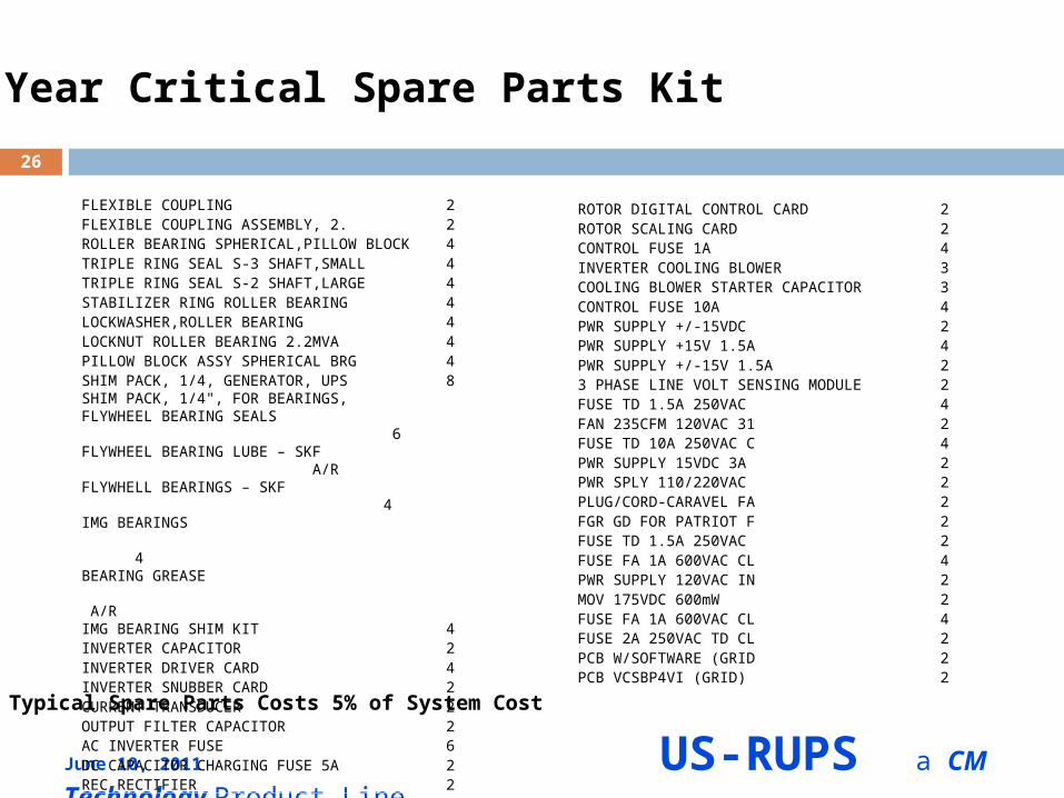
5 Year Critical Spare Parts Kit
FLEXIBLE COUPLING 2FLEXIBLE COUPLING ASSEMBLY, 2. 2ROLLER BEARING SPHERICAL,PILLOW BLOCK 4TRIPLE RING SEAL S-3 SHAFT,SMALL 4TRIPLE RING SEAL S-2 SHAFT,LARGE 4STABILIZER RING ROLLER BEARING 4LOCKWASHER,ROLLER BEARING 4LOCKNUT ROLLER BEARING 2.2MVA 4PILLOW BLOCK ASSY SPHERICAL BRG 4SHIM PACK, 1/4, GENERATOR, UPS 8SHIM PACK, 1/4", FOR BEARINGS,FLYWHEEL BEARING SEALS 6FLYWHEEL BEARING LUBE – SKF A/RFLYWHELL BEARINGS – SKF 4IMG BEARINGS 4BEARING GREASE A/RIMG BEARING SHIM KIT 4INVERTER CAPACITOR 2INVERTER DRIVER CARD 4INVERTER SNUBBER CARD 2CURRENT TRANSDUCER 2OUTPUT FILTER CAPACITOR 2AC INVERTER FUSE 6DC CAPACITOR CHARGING FUSE 5A 2REC RECTIFIER 2
ROTOR DIGITAL CONTROL CARD 2ROTOR SCALING CARD 2CONTROL FUSE 1A 4INVERTER COOLING BLOWER 3COOLING BLOWER STARTER CAPACITOR 3CONTROL FUSE 10A 4PWR SUPPLY +/-15VDC 2PWR SUPPLY +15V 1.5A 4PWR SUPPLY +/-15V 1.5A 23 PHASE LINE VOLT SENSING MODULE 2FUSE TD 1.5A 250VAC 4FAN 235CFM 120VAC 31 2FUSE TD 10A 250VAC C 4PWR SUPPLY 15VDC 3A 2PWR SPLY 110/220VAC 2PLUG/CORD-CARAVEL FA 2FGR GD FOR PATRIOT F 2FUSE TD 1.5A 250VAC 2FUSE FA 1A 600VAC CL 4PWR SUPPLY 120VAC IN 2MOV 175VDC 600mW 2FUSE FA 1A 600VAC CL 4FUSE 2A 250VAC TD CL 2PCB W/SOFTWARE (GRID 2PCB VCSBP4VI (GRID) 2
Typical Spare Parts Costs 5% of System Cost
27
Hot Questions & Cool Answers
Thank you for Considering US-RUPS Rotary Products and System Solutions.
June 10, 2011 US-RUPS a CM Technology Product Line


