1 Dimensional Control for the National Compact Stellarator Experiment R. Ellis, A. Brooks, T. Brown, W. Reiersen, S. Raftopoulos, B. Stratton Presented at the 22 nd Symposium on Fusion Engineering June 2007, Albuquerque, New Mexico
Transcript
1
Dimensional Control for the National Compact Stellarator Experiment
R. Ellis, A. Brooks, T. Brown, W. Reiersen, S. Raftopoulos, B. Stratton
Presented at the 22nd Symposium on Fusion Engineering
June 2007, Albuquerque, New Mexico
2
Outline of Talk
• NCSX Overview• Dimensional Control Requirements• Measurement Technology• Dimensional Control of Modular Coils and Field Period Assembly• Half Period Assembly Trials• Summary
3
NCSX Overview
• NCSX is the centerpiece of the U.S. effort to develop the physics of the compact stellarator.
• Quasi Symmetric• 18 Modular Coils
– 6 each of type A, B, and C– Modular coils are connected by bolted
joints with shims.
• 18 Toroidal Field Coils• 6 pairs of Poloidal Field Coils• Trim coils• Major Radius 1.4m• Aspect Ratio 4.4• Magnetic Field 1.2T – 1.7T
4
Dimensional Control Requirements Result from Consideration of Many Design Issues
• Physics requirements on installed coil current centers.• Coil tolerances.• Allocation of tolerances for different assembly steps.• As-wound accuracy of modular coils.• Possible improvements through coil realignments after manufacture.
5
The Physics Requirements for Dimensional Control Relate to Field Errors
• The toroidal flux in island regions due to fabrication errors, magnetic materials, and eddy currents shall not exceed 10% of the total toroidal flux in the plasma.
• Tolerances were set based partially on experiences of other machines.– 1 part in 1000, or 1.5mm [.060in] for a 1.5m machine.
• Extensive tolerance studies were performed to verify that, with trim coils, this tolerance will result in the desired field quality.
• Tolerances on coils further from the plasma were relaxed, because they have less impact on field errors.
• Field error correction [trim] coils shall be provided to compensate for fabrication deviations.
6
The Physics Requirements Led to a Set of Coil Tolerance Specifications
• These coil tolerances pertain to the location of the current centers of the installed coils relative to the ideal [theoretical] position.– Modular Coils +/- 1.5mm [.060in]
– PF Coils +/- 3.0mm [.120in]
– TF Coils +/- 3.0mm [.120in]
– Trim Coils +/- 3.0mm [.120in]
• The modular coils are the most critical.• An allocation of the modular coil tolerance for each major assembly
step has been defined.
7
Tolerances are Allocated to Each Modular Coil Assembly Step
• Vendor machining and in-house winding +/- 0.5mm [.020in]– Manufacturing deviations in the winding forms are compensated for
during winding.– Realignment offers a chance for improved performance.
• Half Period [3-pack] Assembly [B-A, C-B] +/- 0.25mm [.010in]– We expect this to be the most difficult requirement. – Flange to flange alignment determines overall alignment.– A-A alignment performed prior to half period assembly.
• Full period assembly over vacuum vessel– HPA + FPA tolerance = 0.5mm [.020in].– A-A alignment will bring us close to this goal.
• 3 period assembly in test cell +/- 0.5mm [.020in]– C-C alignment
8
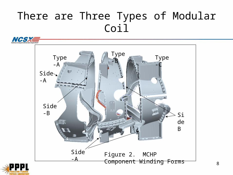
There are Three Types of Modular Coil
Type-A
Type-B
Type-C
Figure 2. MCHP Component Winding Forms
Side-A
Side-B Sid
eB
Side-A
9
The Assembly Tolerances are at the Limits of our Measurement Technology
• The position of the coil throughout assembly is defined by a set of fiducial monuments.– The winding geometry is measured in a coordinate system referenced to
these monuments.
• A mechanical measuring arm is used for the coil winding process.• A laser tracker is used for subsequent assembly tasks.• Measurement software works with the measurement arm, laser
tracker and CAD models to expedite measurement of each winding form.
10
The Position of the Coil is Defined by a Set of Fiducial Monuments on the Winding Form
• Most monuments are 0.5in diameter tooling balls that fit into precise .25in diameter holes.
• During MCWF manufacture, 9 holes [10 on type C] are drilled into each flange.
• At PPPL, monuments for the probe on the measuring arm are installed on each MCWF.– Conical seats accept the 15mm diameter probe tip.
– Coil winding measurements are taken with respect to the conical seats.
• After coil winding, receptacles for additional tooling balls are welded to the MCWF body.
• Positions of all tooling balls are measured with respect to conical seats.– Position of coil current centers w.r.t. tooling balls is established.
11
Mechanical Arm and a Laser Tracker are Used During Manufacture/Assembly
• Mechanical arm is used during coil winding.– The modular coil is mounted in
a ring which can be rotated in the winding fixture.
– The conical seats are used to establish a coordinate system for measurement of winding geometry.
– Each time the ring is rotated, the conical seats are used to re-establish the coordinate system for measuring the windings.
• Laser tracker is used for subsequent operations.– Covers a larger assembly.
12
Measurement Software Works with Measuring Arm/Laser/CAD Models
• A coordinate system is established by measuring a number of points, and performing a best fit to the corresponding locations on the CAD model.– More points more confidence in best fit.
– ~8 points are typically used to establish a coordinate system.
• The quality of the best fit is verified by checking the rms and maximum deviations.
• A variety of output formats are available after measurements.– IGES file for further CAD processing.
– Spreadsheet format
13
Modular Coil Current Centers Have Been Positioned Within Accuracy Requirements
• Some locations of winding surfaces were up to .050in out of position.
• Adjustments were made during coil winding to improve accuracy of current center position.
A B
Base
Septum
14
1
15
5
10
20
96
90
85
25
60
40
Type C Modular Coil, Clamp Number Convention and Side A/B Designation
Some As-Built Dimensions of Type C Coils are Out of Tolerance
Comparison of Winding Form Measurements for C1 thru C5Side A Septum (x1)
-0.0600
-0.0400
-0.0200
0.0000
0.0200
0.0400
0.0600
0 10 20 30 40 50 60 70 80 90 100
Clamp#
Off
se
t, i
n
C1
C2
C3
C4
C5
16
Comparison of Winding Form Measurements for C1 thru C5Side A Base (y1)
-0.0600
-0.0400
-0.0200
0.0000
0.0200
0.0400
0.0600
0 10 20 30 40 50 60 70 80 90 100
Clamp#
Off
set,
in
C1
C2
C3
C4
C5
Some As-Built Dimensions of Type C Coils are Out of Tolerance
17
Adjustments During Winding can Correct Manufacturing Variations
• Adjustable clamps allow tailoring of the cross section of the winding pack on either side of the septum.
• As-built winding form measurements are used to set clamp positions.
• Clamp positions define a cross section of the winding pack.
• Compliance of the insulation, prior to potting, allows for adjustments.
• As-wound coils are mostly within tolerance
Current Center Shifts Relative to Targets for C1 thru C5Lateral
-0.040
-0.030
-0.020
-0.010
0.000
0.010
0.020
0.030
0.040
0.050
0 20 40 60 80 100
Clamp#
Sh
ift, in
ch
es
C1
C2
C3
C4
C5
Max Tol
Min Tol
Current Center Shifts Relative to Targets for C1 thru C5Radial
-0.060
-0.050
-0.040
-0.030
-0.020
-0.010
0.000
0.010
0.020
0.030
0.040
0 20 40 60 80 100
Clamp#
Sh
ift, in
ch
es
C1
C2
C3
C4
C5
Max Tol
Min Tol
18
Half Period Assembly
• The 0.25mm [.010in] tolerance for half period assembly is possibly the most stringent requirement in the assembly sequence.– Modular coils are ~2m [79in] “diameter”.
– Modular coils are not rigid bodies.
• Precise assembly is necessary for proper load sharing between shims, as well as for dimensional control.
• An integrated metrology and assembly sequence has been prepared.– Laser metrology will play a key role in assembling the modular coils
within the tolerance goal.
– Fujipaper is used to monitor shim compression.
– Stiff fixtures are required for assembly.
• Results of initial trials are encouraging.
19
An Integrated Assembly Sequence has been Prepared
• Prior to assembly, the locations of all tooling balls on each modular coil are measured, and the side “A” flange is scanned.– It is necessary to reposition the laser tracker several times around the
periphery of the coil, in order to see all of the monuments.
• The different scans overlap.
• Measurements of a given monument from different positions illustrate the accuracy of the process.
• The coordinate system for this measurement is established from the conical seats.– Locations of new monuments are established.
– Locations of original monuments are verified.
– The coil current centers are now linked to the tooling ball positions.
• The first coil is placed on the assembly fixture, “B” side up.
20
Assembly Sequence…
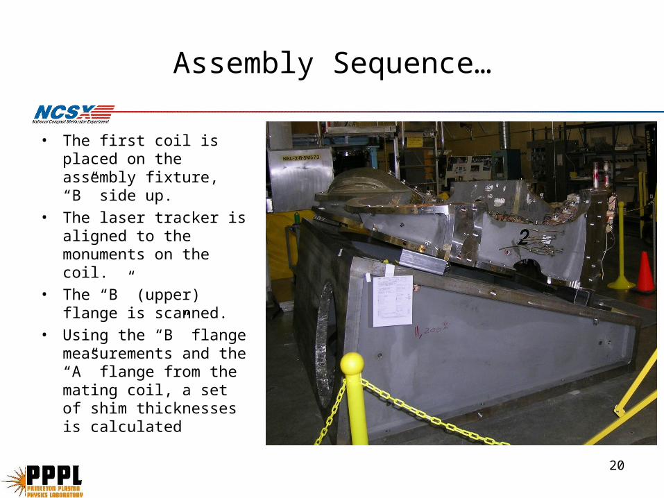
• The first coil is placed on the assembly fixture, “B” side up.
• The laser tracker is aligned to the monuments on the coil.
• The “B” (upper) flange is scanned.
• Using the “B” flange measurements and the “A” flange from the mating coil, a set of shim thicknesses is calculated
21
Assembly Sequence…
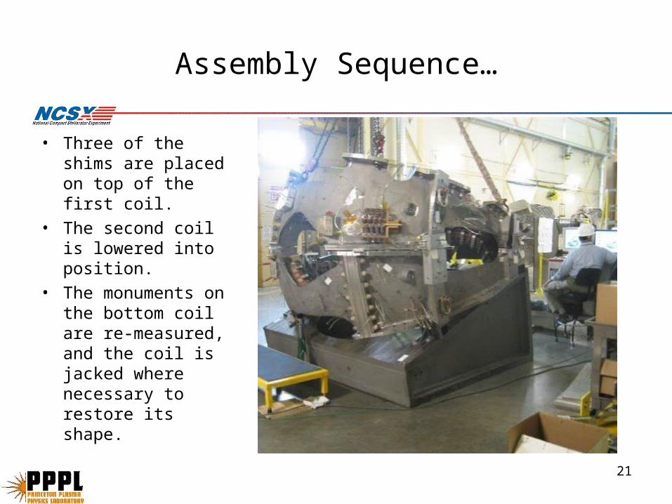
• Three of the shims are placed on top of the first coil.
• The second coil is lowered into position.
• The monuments on the bottom coil are re-measured, and the coil is jacked where necessary to restore its shape.
22
Assembly Sequence…
• The positions of three selected monuments on the top coil are measured.
• These locations are compared to theoretical locations, and a position adjustment of the upper coil is defined.
• This step is repeated until a satisfactory result is obtained.
23
Assembly Sequence…
• The steps for mating the first two coils in a half period are repeated, on a different fixture, when the third coil is joined.
• The new fixture is tilted 40deg instead of 20deg, so that the mating surface will be horizontal.
• Because the top flange of the second [middle] coil is measured in its as-assembled condition, the accumulation of errors is minimized.
• A complete field period is assembled by bolting two half periods together at the interface between two “A” coils.
• Pre-fitting two mating type A coils prior to half period assembly will maximize the likelihood of successful full period assembly with a minimum of iterations.
• A trial of the A-A fitup will demonstrate the feasibility of our assembly sequence.
24
A1-A2 Fitup Trials
• The A1 and A2 coils were pre-assembled using the steps described previously.
• Shim thicknesses were calculated, a uniform .008in compensation was added, and a full set of ground stainless steel shims was fabricated.– The .008in compensation, in retrospect, should not have been used.
• Fujipaper [.005in thick] was added to each shim.• Tooling ball positions were measured before and after bolts were
tightened.
25
A1-A2 Fit-up trials Verify Feasibility of Assembly Sequence
• The bottom [A2] coil maintains its shape.
• The mating flanges track each other.
• The two flanges of the top [A1] coil track each other.
A1-A2 Fitup Ground Shim Test; z deviations vs poloidal angle after torquing
-0.020
-0.015
-0.010
-0.005
0.000
0.005
0.010
0.015
0.020
-180 -120 -60 0 60 120 180
poloidal angle (deg)
de
via
tio
n (
in)
A2 Flange A
A1 Flange A
A1 Flange B
26
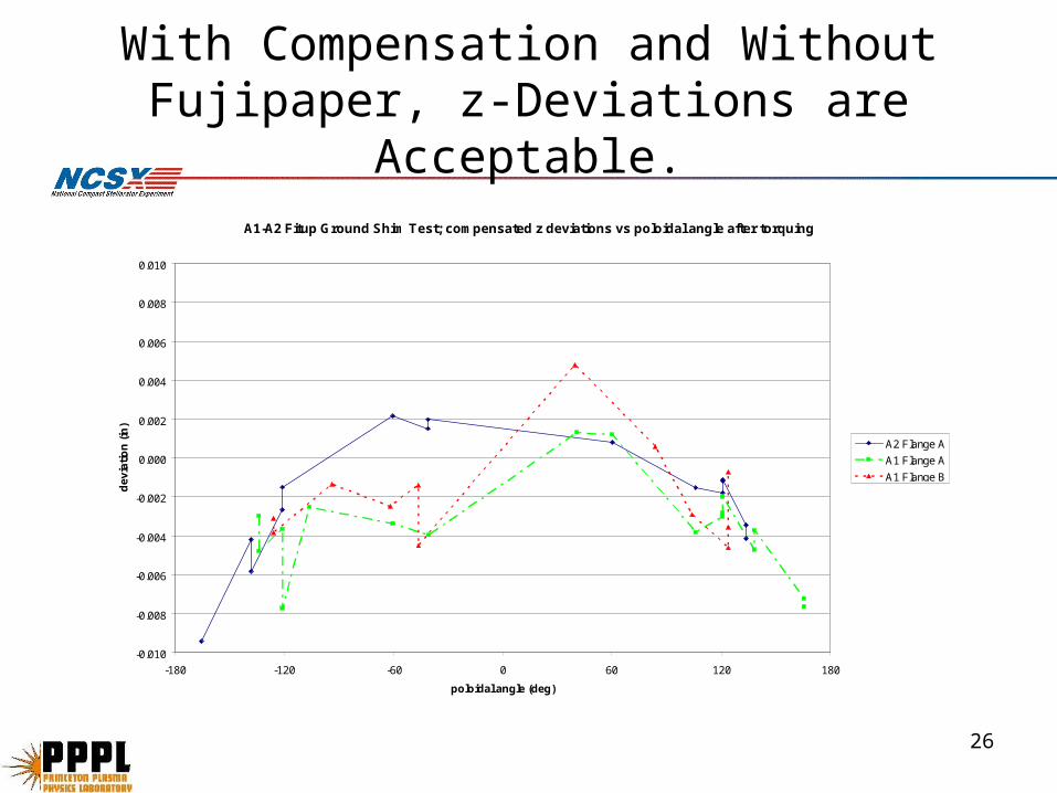
With Compensation and Without Fujipaper, z-Deviations are Acceptable.
A1-A2 Fitup Ground Shim Test; compensated z deviations vs poloidal angle after torquing
-0.010
-0.008
-0.006
-0.004
-0.002
0.000
0.002
0.004
0.006
0.008
0.010
-180 -120 -60 0 60 120 180
poloidal angle (deg)
de
via
tio
n (
in)
A2 Flange A
A1 Flange A
A1 Flange B
27
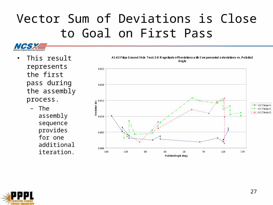
Vector Sum of Deviations is Close to Goal on First Pass
• This result represents the first pass during the assembly process.
– The assembly sequence provides for one additional iteration.
A1-A2 Fitup Ground Shim Test; 3-D Magnitude of Deviations with Compensated z-deviations vs. Poloidal Angle
0.000
0.005
0.010
0.015
0.020
0.025
-180 -130 -80 -30 20 70 120 170
Poloidal Angle (deg)
De
via
tio
n (
in)
A2 Flange A
A1 Flange A
A1 Flange B
28
Fujipaper Shows Acceptable Load Sharing
29
Summary
• Dimensional control for the modular coil manufacturing process has been implemented, and the desired tolerances have been achieved.
• Dimensional control and assembly procedures for the half period and full period assembly steps are nearing completion.
• Initial tests are encouraging.– The knowledge gained from the first full period assembly will be applied
to the assembly of the entire machine, including toroidal field and poloidal field coils.


![Diagnostic set-up and modelling for investigation of ...€¦ · The superconducting stellarator Wendelstein 7-X (W7-X) [2], a drift-optimized stellarator with improved neoclassical](https://static.documents.pub/doc/80x56/60f8323f8543a621ad7ffe85/diagnostic-set-up-and-modelling-for-investigation-of-the-superconducting-stellarator.jpg)