120
ECE 545 – Introduction to VHDL 1 ECE 545 Lecture 4 Behavioral & Structural Design Styles
| Date post: | 04-Jan-2016 |
| Category: |
Documents |
| Upload: | bruce-mills |
| View: | 240 times |
| Download: | 3 times |

ECE 545 – Introduction to VHDL 1
ECE 545Lecture 4
Behavioral & StructuralDesign Styles
ECE 545 – Introduction to VHDL 2
Resources
• Volnei A. Pedroni, Circuit Design with VHDL
Chapter 6, Sequential Code (sections 6.1-6.4)
Chapter 10, Packages and Components
Chapter 7.1, Constant
• Sundar Rajan, Essential VHDL: RTL Synthesis
Done Right
Chapter 4, Registers and Latches
Chapter 9, Design Partitioning
ECE 545 – Introduction to VHDL 3
Behavioral Design Style
for Testbenches
ECE 545 – Introduction to VHDL 4
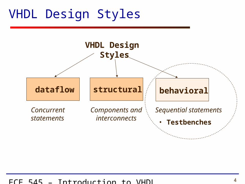
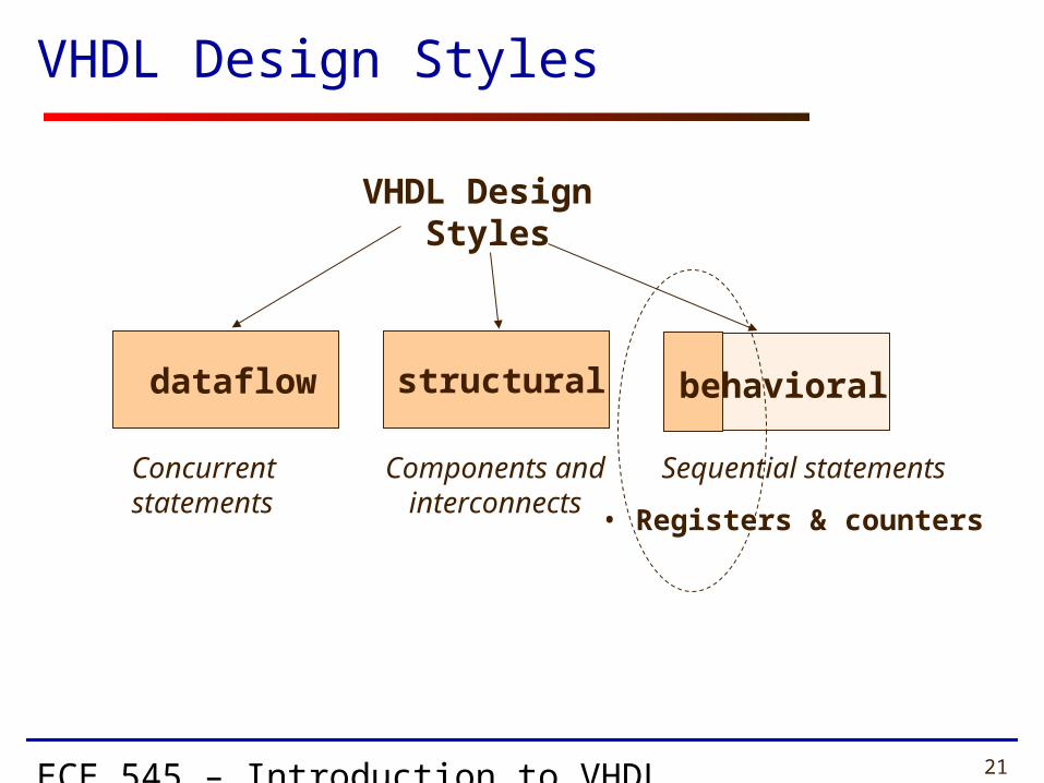
VHDL Design Styles
Components andinterconnects
structural
VHDL Design Styles
dataflow
Concurrent statements
behavioral
• Testbenches
Sequential statements

ECE 545 – Introduction to VHDL 5
Anatomy of a Process
[label:] process [(sensitivity list)] [declaration part]begin statement partend process [label];
OPTIONAL
ECE 545 – Introduction to VHDL 6
Statement Part
• Contains Sequential Statements to be Executed Each Time the Process Is Activated
• Analogous to Conventional Programming Languages

ECE 545 – Introduction to VHDL 7
• A process can be given a unique name using an optional LABEL
• This is followed by the keyword PROCESS
• The keyword BEGIN is used to indicate the start of the process
• All statements within the process are executed SEQUENTIALLY. Hence, order of statements is important.
• A process must end with the keywords END PROCESS.
TESTING: process begin
TEST_VECTOR<=“00”;wait for 10 ns;
TEST_VECTOR<=“01”;wait for 10 ns;
TEST_VECTOR<=“10”;wait for 10 ns;
TEST_VECTOR<=“11”;wait for 10 ns;
end process;
• A process is a sequence of instructions referred to as sequential statements.
What is a PROCESS?
The Keyword PROCESS
ECE 545 – Introduction to VHDL 8
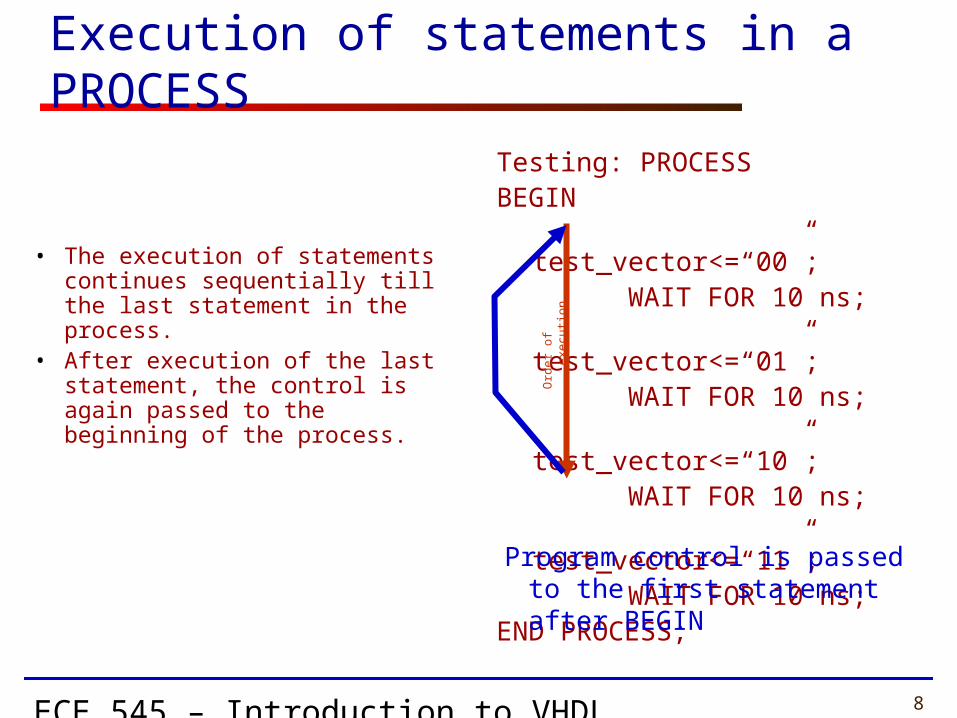
Execution of statements in a PROCESS
• The execution of statements continues sequentially till the last statement in the process.
• After execution of the last statement, the control is again passed to the beginning of the process.
Testing: PROCESS BEGIN
test_vector<=“00”;WAIT FOR 10 ns;test_vector<=“01”;WAIT FOR 10 ns;test_vector<=“10”;WAIT FOR 10 ns;test_vector<=“11”;WAIT FOR 10 ns;
END PROCESS;O
rde
r o
f exe
cutio
nProgram control is passed to the
first statement after BEGIN
ECE 545 – Introduction to VHDL 9
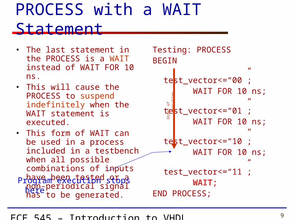
PROCESS with a WAIT Statement
• The last statement in the PROCESS is a WAIT instead of WAIT FOR 10 ns.
• This will cause the PROCESS to suspend indefinitely when the WAIT statement is executed.
• This form of WAIT can be used in a process included in a testbench when all possible combinations of inputs have been tested or a non-periodical signal has to be generated.
Testing: PROCESSBEGIN
test_vector<=“00”;WAIT FOR 10 ns;test_vector<=“01”;WAIT FOR 10 ns;test_vector<=“10”;WAIT FOR 10 ns;test_vector<=“11”;WAIT;
END PROCESS;
Program execution stops here
Ord
er
of e
xecu
tion
ECE 545 – Introduction to VHDL 10
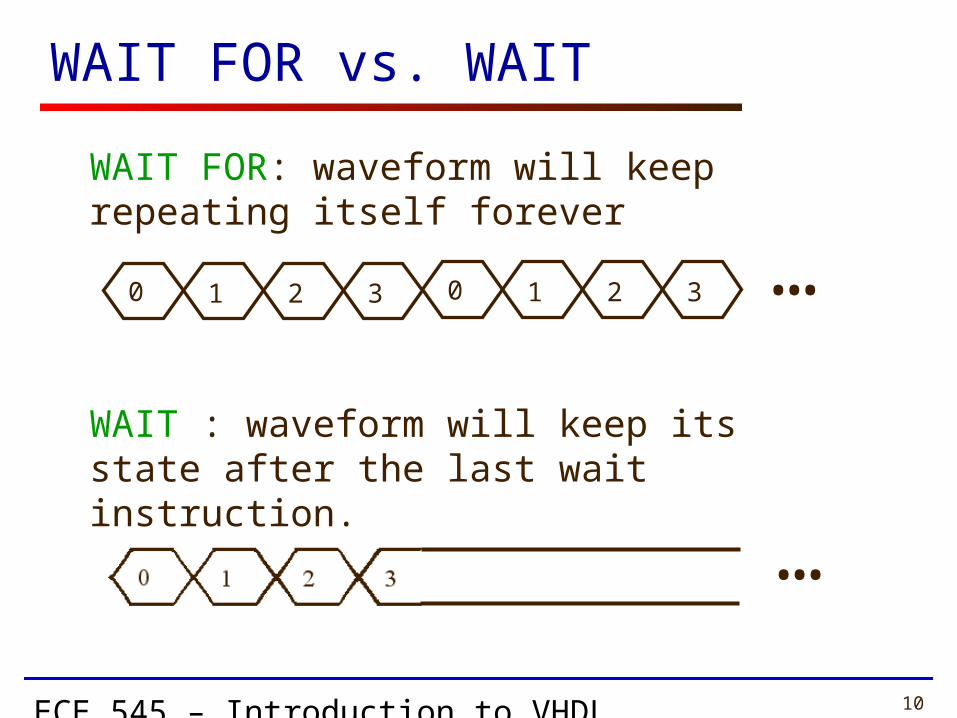
WAIT FOR vs. WAIT
WAIT FOR: waveform will keep repeating itself forever
WAIT : waveform will keep its state after the last wait instruction.
0 1 2 3
…
0 1 2 3 …

ECE 545 – Introduction to VHDL 11
PROCESS with a SENSITIVITY LIST
• List of signals to which the process is sensitive.
• Whenever there is an event on any of the signals in the sensitivity list, the process fires.
• Every time the process fires, it will run in its entirety.
• WAIT statements are NOT ALLOWED in a processes with SENSITIVITY LIST.
label: process (sensitivity list) declaration part begin
statement part end process;
ECE 545 – Introduction to VHDL 12
Testbenches
ECE 545 – Introduction to VHDL 13
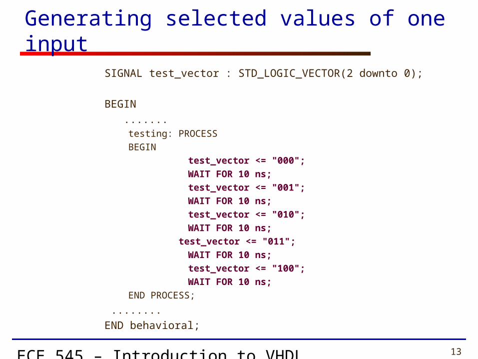
Generating selected values of one input
SIGNAL test_vector : STD_LOGIC_VECTOR(2 downto 0);
BEGIN
.......testing: PROCESS
BEGIN
test_vector <= "000";
WAIT FOR 10 ns;
test_vector <= "001";
WAIT FOR 10 ns;
test_vector <= "010";
WAIT FOR 10 ns;
test_vector <= "011";
WAIT FOR 10 ns;
test_vector <= "100";
WAIT FOR 10 ns;
END PROCESS;
........
END behavioral;
ECE 545 – Introduction to VHDL 14
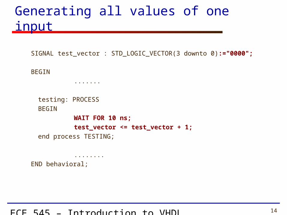
Generating all values of one input
SIGNAL test_vector : STD_LOGIC_VECTOR(3 downto 0):="0000";
BEGIN
.......
testing: PROCESS
BEGIN
WAIT FOR 10 ns;
test_vector <= test_vector + 1;
end process TESTING;
........
END behavioral;

ECE 545 – Introduction to VHDL 15
SIGNAL test_ab : STD_LOGIC_VECTOR(1 downto 0);
SIGNAL test_sel : STD_LOGIC_VECTOR(1 downto 0);
BEGIN
.......
double_loop: PROCESSBEGIN
test_ab <="00";test_sel <="00";for I in 0 to 3 loop for J in 0 to 3 loop
wait for 10 ns; test_ab <= test_ab + 1;
end loop; test_sel <= test_sel + 1;end loop;
END PROCESS;
........
END behavioral;
Generating all possible values of two inputs

ECE 545 – Introduction to VHDL 16
Generating periodical signals, such as clocks
CONSTANT clk1_period : TIME := 20 ns;
CONSTANT clk2_period : TIME := 200 ns;
SIGNAL clk1 : STD_LOGIC;
SIGNAL clk2 : STD_LOGIC := ‘0’;
BEGIN
.......
clk1_generator: PROCESS
clk1 <= ‘0’;
WAIT FOR clk1_period/2;
clk1 <= ‘1’;
WAIT FOR clk1_period/2;
END PROCESS;
clk2 <= not clk2 after clk2_period/2;
.......
END behavioral;

ECE 545 – Introduction to VHDL 17
Generating one-time signals, such as resets
CONSTANT reset1_width : TIME := 100 ns;
CONSTANT reset2_width : TIME := 150 ns;
SIGNAL reset1 : STD_LOGIC;
SIGNAL reset2 : STD_LOGIC := ‘1’;
BEGIN
.......
reset1_generator: PROCESS
reset1 <= ‘1’;
WAIT FOR reset_width;
reset1 <= ‘0’;
WAIT;
END PROCESS;
reset2_generator: PROCESS
WAIT FOR reset_width;
reset2 <= ‘0’;
WAIT;
END PROCESS;
.......
END behavioral;
ECE 545 – Introduction to VHDL 18
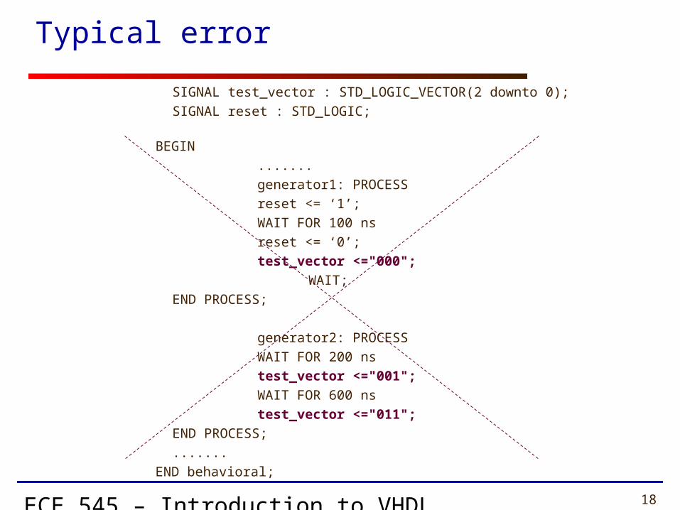
Typical error
SIGNAL test_vector : STD_LOGIC_VECTOR(2 downto 0);
SIGNAL reset : STD_LOGIC;
BEGIN
.......
generator1: PROCESS
reset <= ‘1’;
WAIT FOR 100 ns
reset <= ‘0’;
test_vector <="000";
WAIT;
END PROCESS;
generator2: PROCESS
WAIT FOR 200 ns
test_vector <="001";
WAIT FOR 600 ns
test_vector <="011";
END PROCESS;
.......
END behavioral;
ECE 545 – Introduction to VHDL 19
Behavioral Design Style
for Synthesis

ECE 545 – Introduction to VHDL 20
Register Transfer Level (RTL) Design Description
Combinational Logic
Combinational Logic
Registers
…
ECE 545 – Introduction to VHDL 21
VHDL Design Styles
Components andinterconnects
structural
VHDL Design Styles
dataflow
Concurrent statements
behavioral
• Registers & counters
Sequential statements

ECE 545 – Introduction to VHDL 22
Component Equivalent of a Process
• All signals which appear on the left of signal assignment statement (<=) are outputs e.g. y, z
• All signals which appear on the right of signal assignment statement (<=) or in logic expressions are inputs e.g. w, a, b, c
• All signals which appear in the sensitivity list are inputs e.g. clk
• Note that not all inputs need to be included in the sensitivity list
priority: PROCESS (clk)BEGIN
IF w(3) = '1' THENy <= "11" ;
ELSIF w(2) = '1' THEN y <= "10" ;
ELSIF w(1) = c THENy <= a and b;
ELSEz <= "00" ;
END IF ;END PROCESS ;
wa
y
zpriority
bc
clk

ECE 545 – Introduction to VHDL 23
Processes in VHDL
• Processes Describe Sequential Behavior
• Processes in VHDL Are Very Powerful Statements• Allow to define an arbitrary behavior that may
be difficult to represent by a real circuit• Not every process can be synthesized
• Use Processes with Caution in the Code to Be Synthesized
• Use Processes Freely in Testbenches

ECE 545 – Introduction to VHDL 24
Registers

ECE 545 – Introduction to VHDL 25
Clock D
0 1 1
– 0 1
0 1
Truth table Graphical symbol
t 1 t 2 t 3 t 4
Time
Clock
D
Q
Timing diagram
Q(t+1)
Q(t)
D latch
D Q
Clock
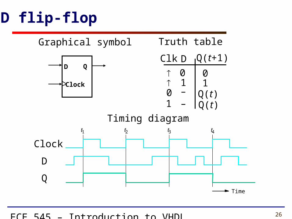
ECE 545 – Introduction to VHDL 26
Clk D
0 1
0 1
Truth table
t 1 t 2 t 3 t 4
Time
Clock
D
Q
Timing diagram
Q(t+1)
Q(t)
D flip-flop
D Q
Clock
Graphical symbol
0 – Q(t)1 –
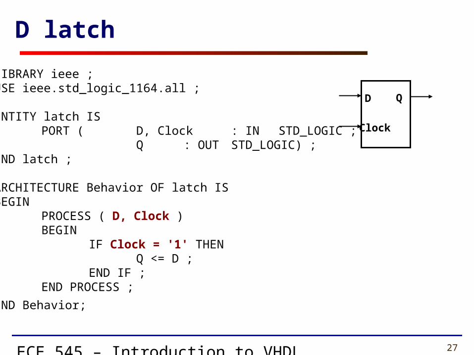
ECE 545 – Introduction to VHDL 27
LIBRARY ieee ; USE ieee.std_logic_1164.all ;
ENTITY latch IS PORT ( D, Clock : IN STD_LOGIC ;
Q : OUT STD_LOGIC) ; END latch ;
ARCHITECTURE Behavior OF latch IS BEGIN
PROCESS ( D, Clock ) BEGIN
IF Clock = '1' THEN Q <= D ;
END IF ; END PROCESS ;
END Behavior;
D latch
D Q
Clock
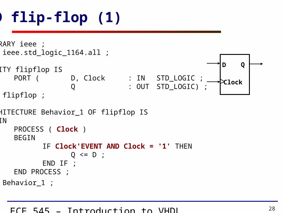
ECE 545 – Introduction to VHDL 28
LIBRARY ieee ; USE ieee.std_logic_1164.all ;
ENTITY flipflop IS PORT ( D, Clock : IN STD_LOGIC ;
Q : OUT STD_LOGIC) ; END flipflop ;
ARCHITECTURE Behavior_1 OF flipflop IS BEGIN
PROCESS ( Clock ) BEGIN
IF Clock'EVENT AND Clock = '1' THEN Q <= D ;
END IF ; END PROCESS ;
END Behavior_1 ;
D flip-flop (1)
D Q
Clock
ECE 545 – Introduction to VHDL 29
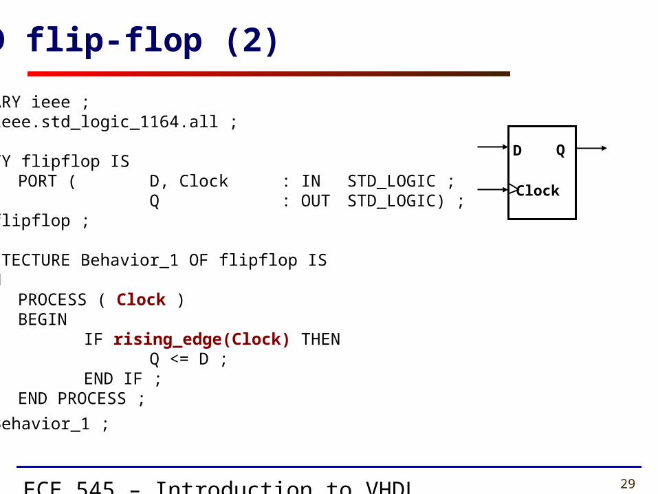
LIBRARY ieee ; USE ieee.std_logic_1164.all ;
ENTITY flipflop IS PORT ( D, Clock : IN STD_LOGIC ;
Q : OUT STD_LOGIC) ; END flipflop ;
ARCHITECTURE Behavior_1 OF flipflop IS BEGIN
PROCESS ( Clock ) BEGIN
IF rising_edge(Clock) THEN Q <= D ;
END IF ; END PROCESS ;
END Behavior_1 ;
D flip-flop (2)
D Q
Clock
ECE 545 – Introduction to VHDL 30
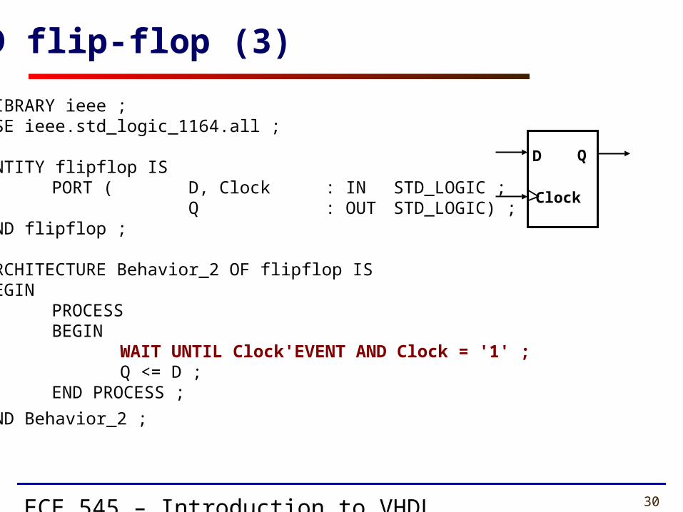
LIBRARY ieee ; USE ieee.std_logic_1164.all ;
ENTITY flipflop IS PORT ( D, Clock : IN STD_LOGIC ;
Q : OUT STD_LOGIC) ; END flipflop ;
ARCHITECTURE Behavior_2 OF flipflop IS BEGIN
PROCESSBEGIN
WAIT UNTIL Clock'EVENT AND Clock = '1' ; Q <= D ;
END PROCESS ;
END Behavior_2 ;
D flip-flop (3)
D Q
Clock
ECE 545 – Introduction to VHDL 31
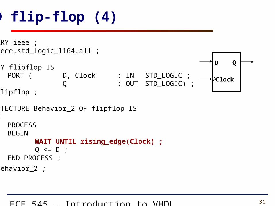
LIBRARY ieee ; USE ieee.std_logic_1164.all ;
ENTITY flipflop IS PORT ( D, Clock : IN STD_LOGIC ;
Q : OUT STD_LOGIC) ; END flipflop ;
ARCHITECTURE Behavior_2 OF flipflop IS BEGIN
PROCESSBEGIN
WAIT UNTIL rising_edge(Clock) ; Q <= D ;
END PROCESS ;
END Behavior_2 ;
D flip-flop (4)
D Q
Clock

ECE 545 – Introduction to VHDL 32
LIBRARY ieee ; USE ieee.std_logic_1164.all ;
ENTITY flipflop IS PORT ( D, Resetn, Clock : IN STD_LOGIC ;
Q : OUT STD_LOGIC) ; END flipflop ;
ARCHITECTURE Behavior OF flipflop IS BEGIN
PROCESS ( Resetn, Clock ) BEGIN
IF Resetn = '0' THEN Q <= '0' ;
ELSIF Clock'EVENT AND Clock = '1' THEN Q <= D ;
END IF ; END PROCESS ;
END Behavior ;
D flip-flop with asynchronous reset
D Q
Clock
Resetn

ECE 545 – Introduction to VHDL 33
LIBRARY ieee ; USE ieee.std_logic_1164.all ; ENTITY flipflop IS
PORT ( D, Resetn, Clock : IN STD_LOGIC ; Q : OUT STD_LOGIC) ;
END flipflop ;
ARCHITECTURE Behavior OF flipflop IS BEGIN
PROCESS BEGIN
WAIT UNTIL Clock'EVENT AND Clock = '1' ; IF Resetn = '0' THEN
Q <= '0' ; ELSE
Q <= D ; END IF ;
END PROCESS ;
END Behavior ;
D flip-flop with synchronous reset
D Q
Clock
Resetn

ECE 545 – Introduction to VHDL 34
8-bit register with asynchronous resetLIBRARY ieee ;USE ieee.std_logic_1164.all ;
ENTITY reg8 ISPORT ( D : IN STD_LOGIC_VECTOR(7 DOWNTO 0) ;
Resetn, Clock : IN STD_LOGIC ;Q : OUT STD_LOGIC_VECTOR(7 DOWNTO 0) ) ;
END reg8 ;
ARCHITECTURE Behavior OF reg8 ISBEGIN
PROCESS ( Resetn, Clock )BEGIN
IF Resetn = '0' THENQ <= "00000000" ;
ELSIF Clock'EVENT AND Clock = '1' THENQ <= D ;
END IF ;END PROCESS ;
END Behavior ;`
Resetn
Clock
reg8
8 8
D Q

ECE 545 – Introduction to VHDL 35
N-bit register with asynchronous reset
LIBRARY ieee ;USE ieee.std_logic_1164.all ;
ENTITY regn ISGENERIC ( N : INTEGER := 16 ) ;PORT ( D : IN
STD_LOGIC_VECTOR(N-1 DOWNTO 0) ;Resetn, Clock : IN STD_LOGIC ;Q : OUT
STD_LOGIC_VECTOR(N-1 DOWNTO 0) ) ;END regn ;
ARCHITECTURE Behavior OF regn ISBEGIN
PROCESS ( Resetn, Clock )BEGIN
IF Resetn = '0' THENQ <= (OTHERS => '0') ;
ELSIF Clock'EVENT AND Clock = '1' THENQ <= D ;
END IF ;END PROCESS ;
END Behavior ;
Resetn
Clock
regn
N N
D Q
ECE 545 – Introduction to VHDL 36
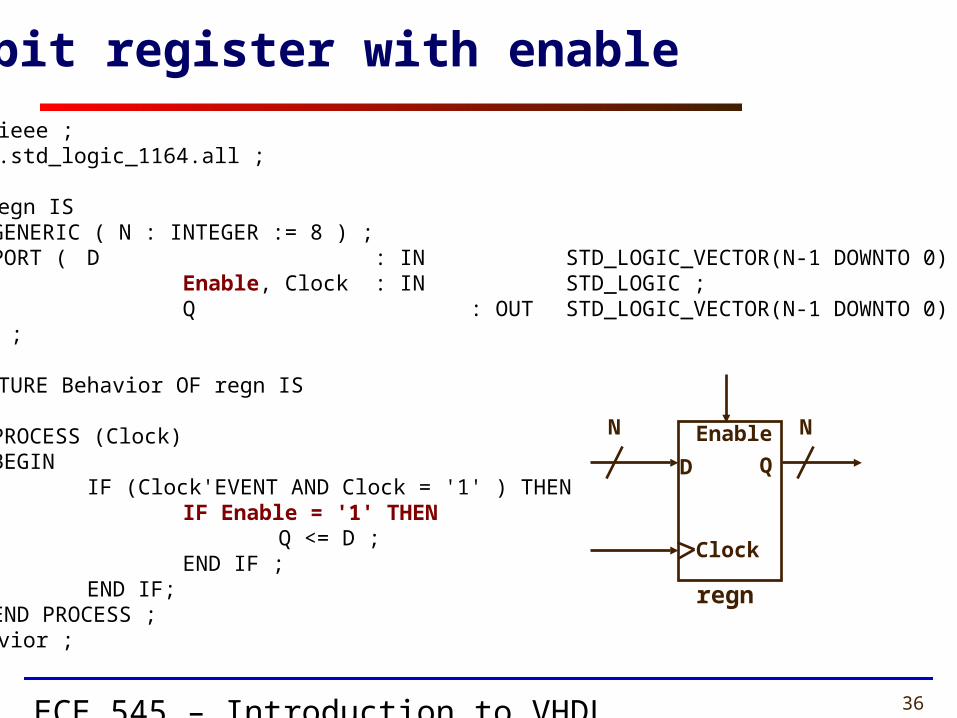
LIBRARY ieee ;USE ieee.std_logic_1164.all ;
ENTITY regn ISGENERIC ( N : INTEGER := 8 ) ;PORT ( D : IN STD_LOGIC_VECTOR(N-1 DOWNTO 0) ;
Enable, Clock : IN STD_LOGIC ;Q : OUT STD_LOGIC_VECTOR(N-1 DOWNTO 0) ) ;
END regn ;
ARCHITECTURE Behavior OF regn ISBEGIN
PROCESS (Clock)BEGIN
IF (Clock'EVENT AND Clock = '1' ) THENIF Enable = '1' THEN
Q <= D ;END IF ;
END IF;END PROCESS ;
END Behavior ;
N-bit register with enable
QD
Enable
Clock
regn
N N

ECE 545 – Introduction to VHDL 37
Counters
ECE 545 – Introduction to VHDL 38
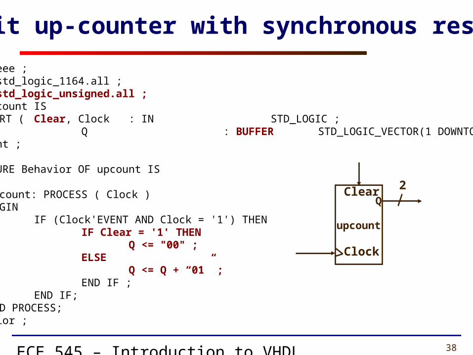
LIBRARY ieee ;USE ieee.std_logic_1164.all ;USE ieee.std_logic_unsigned.all ;ENTITY upcount IS
PORT ( Clear, Clock : IN STD_LOGIC ;Q : BUFFER STD_LOGIC_VECTOR(1 DOWNTO 0) ) ;
END upcount ;
ARCHITECTURE Behavior OF upcount ISBEGIN
upcount: PROCESS ( Clock )BEGIN
IF (Clock'EVENT AND Clock = '1') THENIF Clear = '1' THEN
Q <= "00" ;ELSE
Q <= Q + “01” ;END IF ;
END IF;END PROCESS;
END Behavior ;
2-bit up-counter with synchronous reset
QClear
Clock
upcount
2
ECE 545 – Introduction to VHDL 39
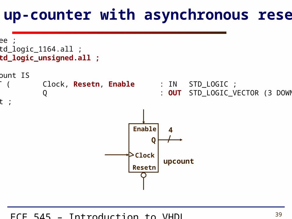
LIBRARY ieee ;USE ieee.std_logic_1164.all ;USE ieee.std_logic_unsigned.all ;
ENTITY upcount ISPORT ( Clock, Resetn, Enable : IN STD_LOGIC ;
Q : OUT STD_LOGIC_VECTOR (3 DOWNTO 0)) ;END upcount ;
4-bit up-counter with asynchronous reset (1)
Q
Enable
Clockupcount
4
Resetn

ECE 545 – Introduction to VHDL 40
ARCHITECTURE Behavior OF upcount ISSIGNAL Count : STD_LOGIC_VECTOR (3 DOWNTO 0) ;
BEGINPROCESS ( Clock, Resetn )BEGIN
IF Resetn = '0' THENCount <= "0000" ;
ELSIF (Clock'EVENT AND Clock = '1') THENIF Enable = '1' THEN
Count <= Count + 1 ;END IF ;
END IF ;END PROCESS ;Q <= Count ;
END Behavior ;
4-bit up-counter with asynchronous reset (2)
Q
Enable
Clockupcount
4
Resetn

ECE 545 – Introduction to VHDL 41
Shift Registers
ECE 545 – Introduction to VHDL 42
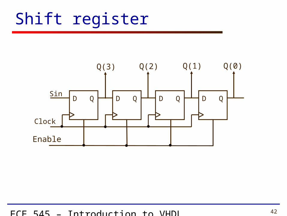
Shift register
D QSin
Clock
D Q D Q D Q
Q(3) Q(2) Q(1) Q(0)
Enable
ECE 545 – Introduction to VHDL 43
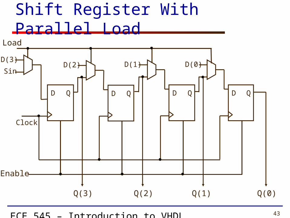
Shift Register With Parallel Load
D(3)
D Q
Clock
Enable
SinD(2)
D Q
D(1)
D Q
D(0)
D Q
Q(0)Q(1)Q(2)Q(3)
Load
ECE 545 – Introduction to VHDL 44
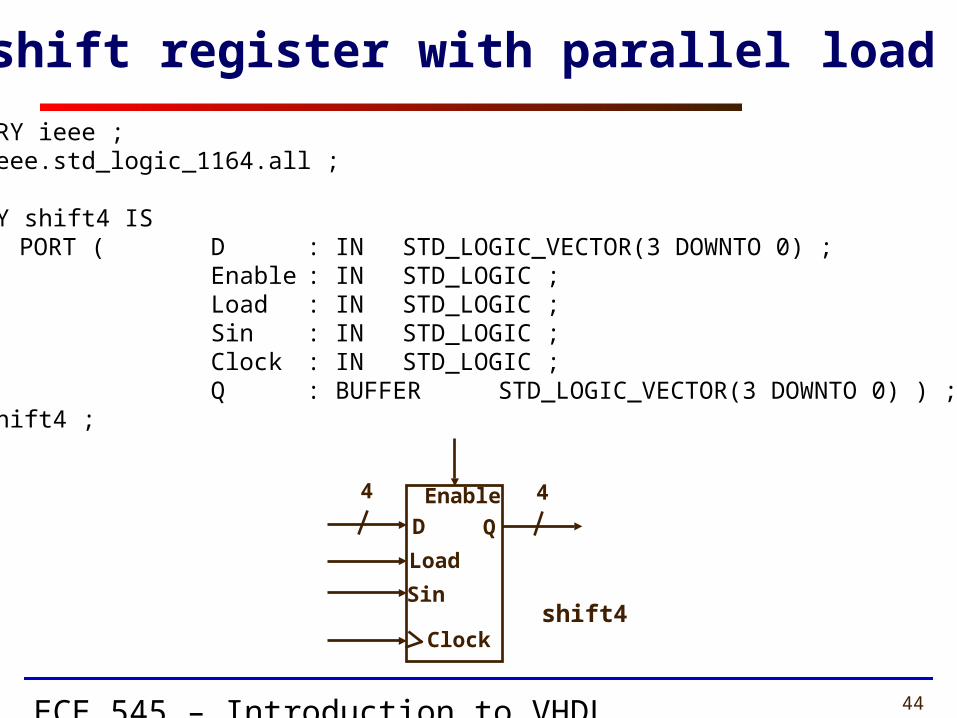
LIBRARY ieee ;USE ieee.std_logic_1164.all ;
ENTITY shift4 ISPORT ( D : IN STD_LOGIC_VECTOR(3 DOWNTO 0) ;
Enable : IN STD_LOGIC ;Load : IN STD_LOGIC ;Sin : IN STD_LOGIC ;Clock : IN STD_LOGIC ;Q : BUFFER STD_LOGIC_VECTOR(3 DOWNTO 0) ) ;
END shift4 ;
4-bit shift register with parallel load (1)
Q
Enable
Clockshift4
4
D
Load
Sin
4
ECE 545 – Introduction to VHDL 45
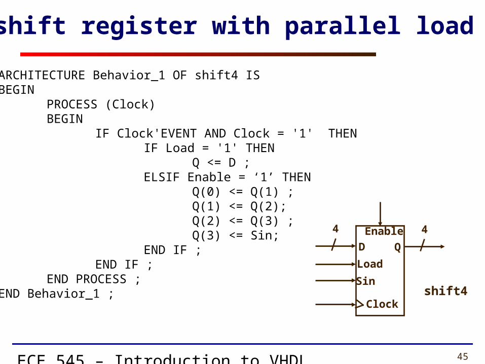
ARCHITECTURE Behavior_1 OF shift4 ISBEGIN
PROCESS (Clock)BEGIN
IF Clock'EVENT AND Clock = '1' THENIF Load = '1' THEN
Q <= D ;ELSIF Enable = ‘1’ THEN
Q(0) <= Q(1) ;Q(1) <= Q(2); Q(2) <= Q(3) ; Q(3) <= Sin;
END IF ;END IF ;
END PROCESS ;END Behavior_1 ;
4-bit shift register with parallel load (2)
Q
Enable
Clockshift4
4
D
Load
Sin
4

ECE 545 – Introduction to VHDL 46
LIBRARY ieee ;USE ieee.std_logic_1164.all ;
ENTITY shiftn ISGENERIC ( N : INTEGER := 8 ) ;PORT ( D : IN STD_LOGIC_VECTOR(N-1 DOWNTO 0) ;
Enable : IN STD_LOGIC ;Load : IN STD_LOGIC ;Sin : IN STD_LOGIC ;Clock : IN STD_LOGIC ;Q : BUFFER STD_LOGIC_VECTOR(N-1 DOWNTO 0) ) ;
END shiftn ;
N-bit shift register with parallel load (1)
Q
Enable
Clockshiftn
N
D
Load
Sin
N
ECE 545 – Introduction to VHDL 47
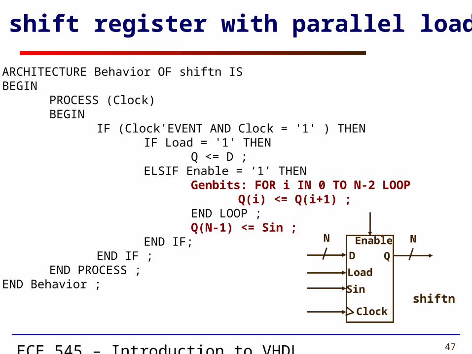
ARCHITECTURE Behavior OF shiftn ISBEGIN
PROCESS (Clock)BEGIN
IF (Clock'EVENT AND Clock = '1' ) THENIF Load = '1' THEN
Q <= D ;ELSIF Enable = ‘1’ THEN
Genbits: FOR i IN 0 TO N-2 LOOPQ(i) <= Q(i+1) ;
END LOOP ;Q(N-1) <= Sin ;
END IF;END IF ;
END PROCESS ;END Behavior ;
N-bit shift register with parallel load (2)
Q
Enable
Clockshiftn
N
D
Load
Sin
N

ECE 545 – Introduction to VHDL 48
If Statement

ECE 545 – Introduction to VHDL 49
Sequential Statements (1)
• If Statement
• else and elsif are optional
if boolean expression then statementselsif boolean expression then statements
else boolean expression then statementsend if;
ECE 545 – Introduction to VHDL 50
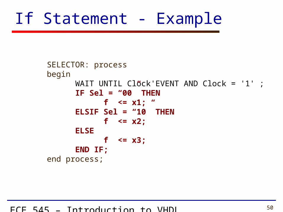
SELECTOR: processbegin
WAIT UNTIL Clock'EVENT AND Clock = '1' ;IF Sel = “00” THEN
f <= x1;ELSIF Sel = “10” THEN
f <= x2;ELSE
f <= x3;END IF;
end process;
If Statement - Example

ECE 545 – Introduction to VHDL 51
Structural Design Style

ECE 545 – Introduction to VHDL 52
VHDL Design Styles
Components andinterconnects
structural
VHDL Design Styles
dataflow
Concurrent statements
behavioral
• Registers & counters
Sequential statements
ECE 545 – Introduction to VHDL 53
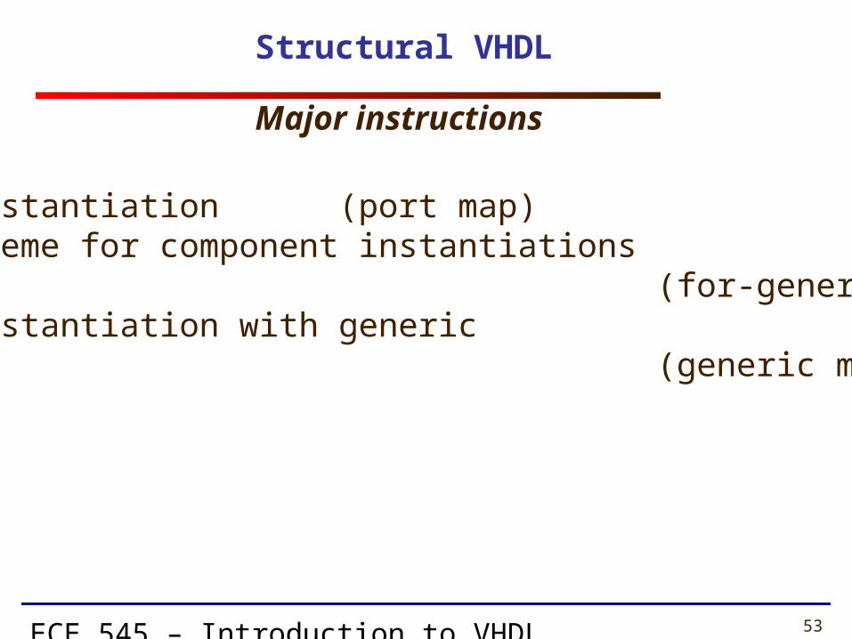
Structural VHDL
• component instantiation (port map)• generate scheme for component instantiations (for-generate)• component instantiation with generic (generic map, port map)
Major instructions
ECE 545 – Introduction to VHDL 54
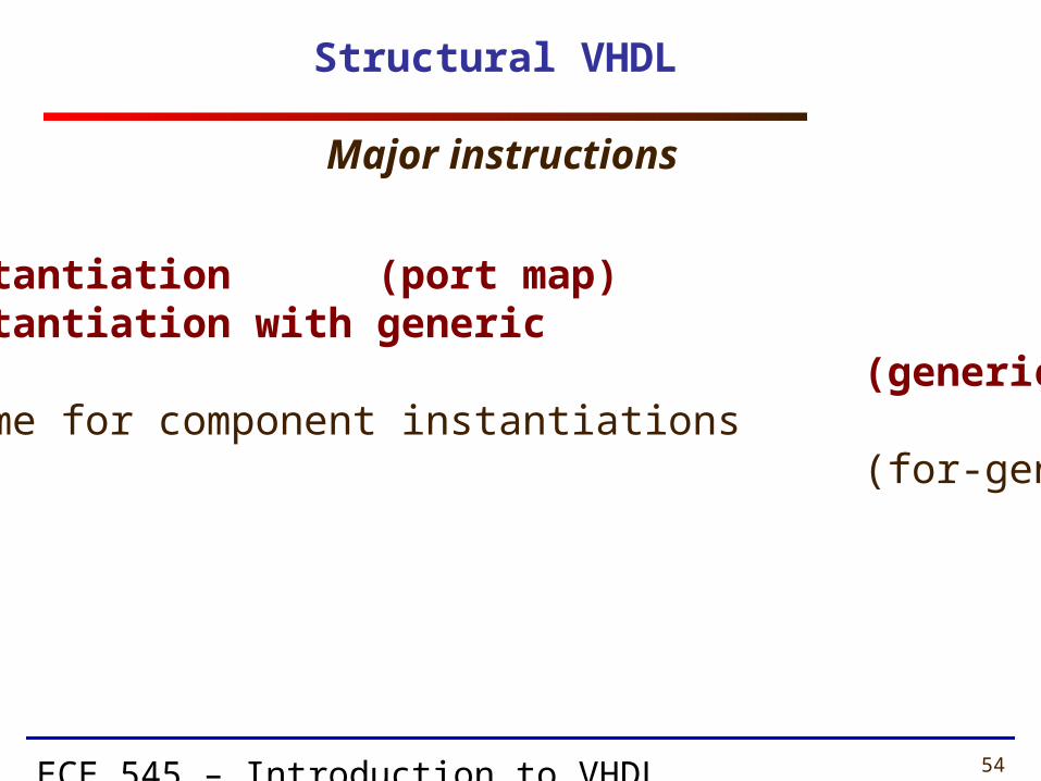
Structural VHDL
• component instantiation (port map)• component instantiation with generic (generic map, port map)• generate scheme for component instantiations (for-generate)
Major instructions

ECE 545 – Introduction to VHDL 55
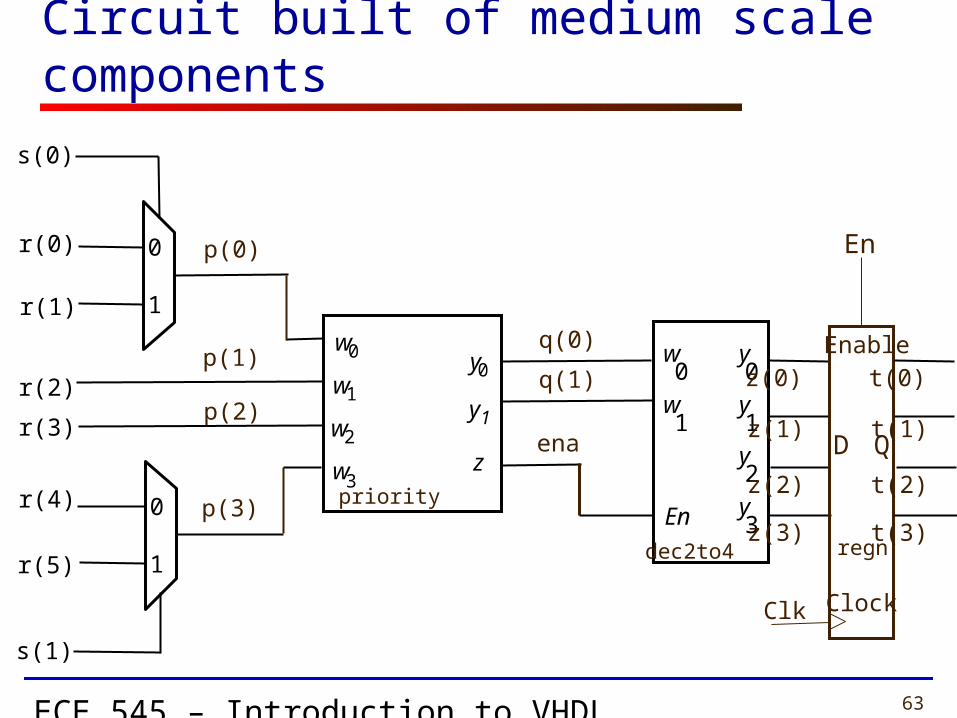
Circuit built of medium scale components
w 0
w 3
y 0
y 1
z
w 1
w 2
w 0
En
y 0
w 1
y 1
y 2
y 3
s(0)
0
1
s(1)
0
1
r(0)
r(1)
r(2)
r(3)
r(4)
r(5)
p(0)
p(1)
p(2)
p(3)
q(0)
q(1)
ena
z(0)
z(1)
z(2)
z(3)dec2to4
priority
z(0)
z(1)
z(2)
z(3)regn
D Q
Clk Clock
Enable
En
ECE 545 – Introduction to VHDL 56
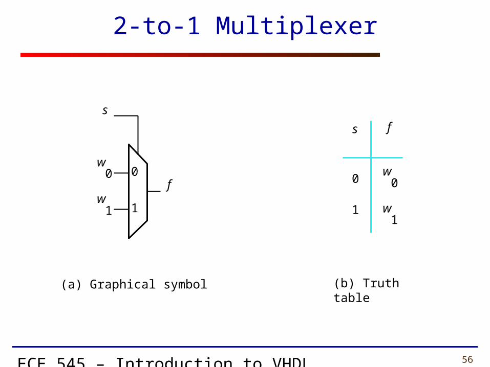
2-to-1 Multiplexer
(a) Graphical symbol (b) Truth table
0
1
fs
w0
w1
f
s
w0
w1
0
1

ECE 545 – Introduction to VHDL 57
VHDL code for a 2-to-1 Multiplexer
LIBRARY ieee ;USE ieee.std_logic_1164.all ;
ENTITY mux2to1 ISPORT ( w0, w1, s : IN STD_LOGIC ;
f : OUT STD_LOGIC ) ;END mux2to1 ;
ARCHITECTURE dataflow OF mux2to1 ISBEGIN
f <= w0 WHEN s = '0' ELSE w1 ;END dataflow ;
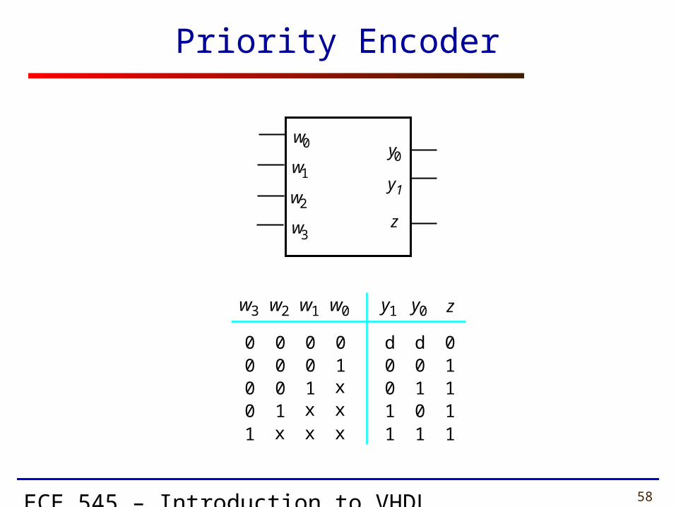
ECE 545 – Introduction to VHDL 58
Priority Encoder
d001
010
w0 y1
d
y0
1 1
01
1
11
z
1xx
0
x
w1
01x
0
x
w2
001
0
x
w3
000
0
1
w 0
w 3
y 0
y 1
z
w 1
w 2
ECE 545 – Introduction to VHDL 59
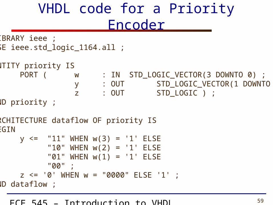
VHDL code for a Priority Encoder
LIBRARY ieee ;USE ieee.std_logic_1164.all ;
ENTITY priority ISPORT ( w : IN STD_LOGIC_VECTOR(3 DOWNTO 0) ;
y : OUT STD_LOGIC_VECTOR(1 DOWNTO 0) ;z : OUT STD_LOGIC ) ;
END priority ;
ARCHITECTURE dataflow OF priority ISBEGIN
y <= "11" WHEN w(3) = '1' ELSE "10" WHEN w(2) = '1' ELSE"01" WHEN w(1) = '1' ELSE"00" ;
z <= '0' WHEN w = "0000" ELSE '1' ;END dataflow ;
ECE 545 – Introduction to VHDL 60
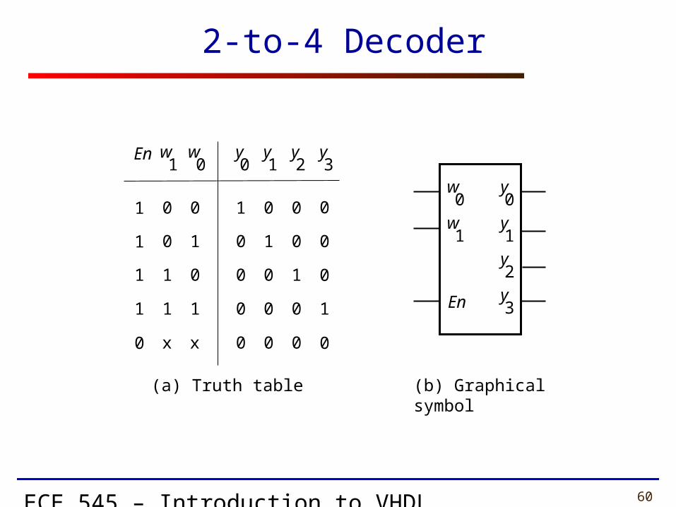
2-to-4 Decoder
0
0
1
1
1
0
1
y 0
w 1
0
w 0
x x
1
1
0
1
1
En
0
0
0
1
0
y 1
1
0
0
0
0
y 2
0
1
0
0
0
y 3
0
0
1
0
0
w 0
En
y 0
w 1
y 1
y 2
y 3
(a) Truth table (b) Graphical symbol
ECE 545 – Introduction to VHDL 61
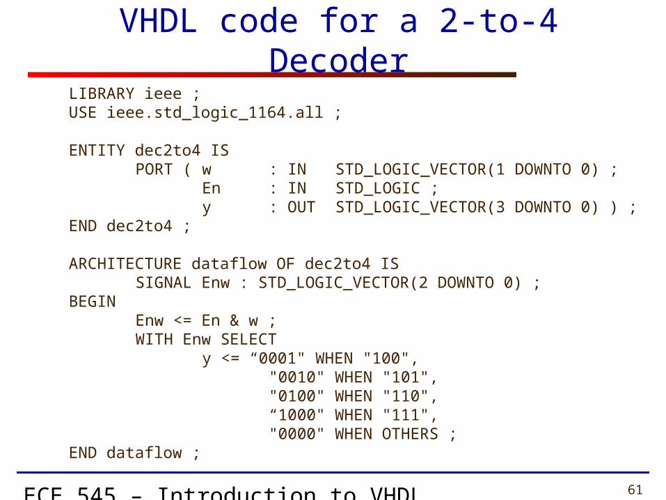
VHDL code for a 2-to-4 Decoder
LIBRARY ieee ;USE ieee.std_logic_1164.all ;
ENTITY dec2to4 ISPORT ( w : IN STD_LOGIC_VECTOR(1 DOWNTO 0) ;
En : IN STD_LOGIC ;y : OUT STD_LOGIC_VECTOR(3 DOWNTO 0) ) ;
END dec2to4 ;
ARCHITECTURE dataflow OF dec2to4 ISSIGNAL Enw : STD_LOGIC_VECTOR(2 DOWNTO 0) ;
BEGINEnw <= En & w ;WITH Enw SELECT
y <= “0001" WHEN "100","0010" WHEN "101","0100" WHEN "110",“1000" WHEN "111","0000" WHEN OTHERS ;
END dataflow ;
ECE 545 – Introduction to VHDL 62
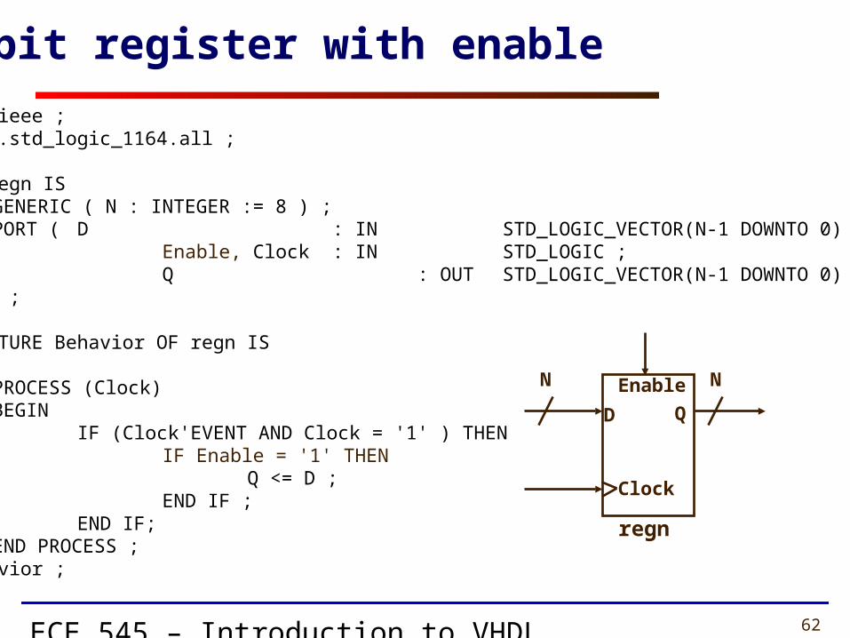
LIBRARY ieee ;USE ieee.std_logic_1164.all ;
ENTITY regn ISGENERIC ( N : INTEGER := 8 ) ;PORT ( D : IN STD_LOGIC_VECTOR(N-1 DOWNTO 0) ;
Enable, Clock : IN STD_LOGIC ;Q : OUT STD_LOGIC_VECTOR(N-1 DOWNTO 0) ) ;
END regn ;
ARCHITECTURE Behavior OF regn ISBEGIN
PROCESS (Clock)BEGIN
IF (Clock'EVENT AND Clock = '1' ) THENIF Enable = '1' THEN
Q <= D ;END IF ;
END IF;END PROCESS ;
END Behavior ;
N-bit register with enable
QD
Enable
Clock
regn
N N
ECE 545 – Introduction to VHDL 63
Circuit built of medium scale components
w 0
w 3
y 0
y 1
z
w 1
w 2
w 0
En
y 0
w 1
y 1
y 2
y 3
s(0)
0
1
s(1)
0
1
r(0)
r(1)
r(2)
r(3)
r(4)
r(5)
p(0)
p(1)
p(2)
p(3)
q(0)
q(1)
ena
z(0)
z(1)
z(2)
z(3)dec2to4
priority
t(0)
t(1)
t(2)
t(3)regn
D Q
Clk Clock
Enable
En

ECE 545 – Introduction to VHDL 64
Structural description – example (1)
LIBRARY ieee ;USE ieee.std_logic_1164.all ;
ENTITY priority_resolver ISPORT (r : IN STD_LOGIC_VECTOR(5 DOWNTO 0) ;
s : IN STD_LOGIC_VECTOR(1 DOWNTO 0) ; clk : IN STD_LOGIC; en : IN STD_LOGIC;
t : OUT STD_LOGIC_VECTOR(3 DOWNTO 0) ) ;END priority_resolver;
ARCHITECTURE structural OF priority_resolver IS
SIGNAL p : STD_LOGIC_VECTOR (3 DOWNTO 0) ;SIGNAL q : STD_LOGIC_VECTOR (1 DOWNTO 0) ;SIGNAL z : STD_LOGIC_VECTOR (3 DOWNTO 0) ;SIGNAL ena : STD_LOGIC ;
ECE 545 – Introduction to VHDL 65
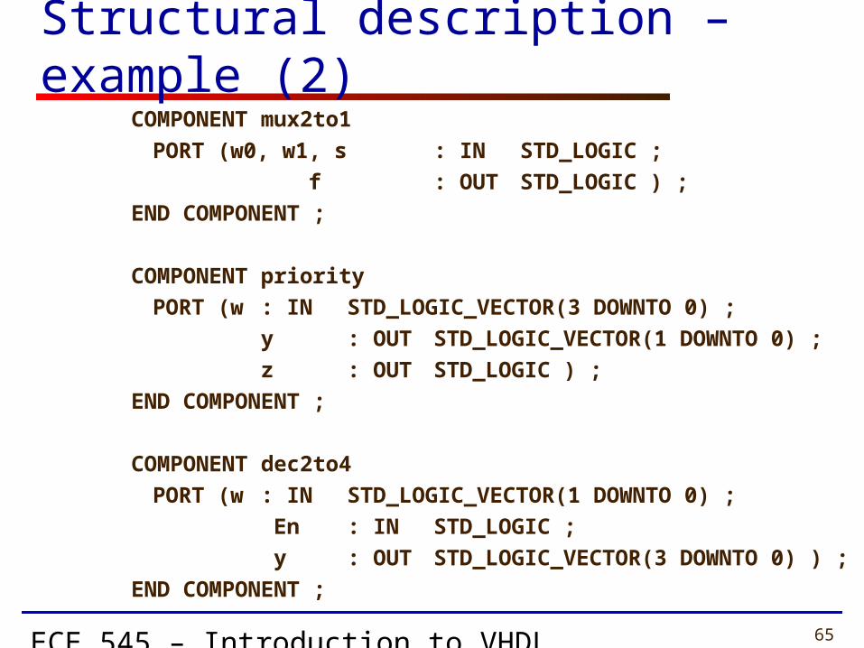
Structural description – example (2)COMPONENT mux2to1
PORT (w0, w1, s : IN STD_LOGIC ;
f : OUT STD_LOGIC ) ;
END COMPONENT ;
COMPONENT priority
PORT (w : IN STD_LOGIC_VECTOR(3 DOWNTO 0) ;
y : OUT STD_LOGIC_VECTOR(1 DOWNTO 0) ;
z : OUT STD_LOGIC ) ;
END COMPONENT ;
COMPONENT dec2to4
PORT (w : IN STD_LOGIC_VECTOR(1 DOWNTO 0) ;
En : IN STD_LOGIC ;
y : OUT STD_LOGIC_VECTOR(3 DOWNTO 0) ) ;
END COMPONENT ;
ECE 545 – Introduction to VHDL 66
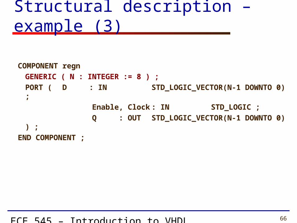
Structural description – example (3)
COMPONENT regn
GENERIC ( N : INTEGER := 8 ) ;
PORT ( D : IN STD_LOGIC_VECTOR(N-1 DOWNTO 0) ;
Enable, Clock : IN STD_LOGIC ;
Q : OUT STD_LOGIC_VECTOR(N-1 DOWNTO 0) ) ;
END COMPONENT ;

ECE 545 – Introduction to VHDL 67
Structural description – example (4) BEGIN
u1: mux2to1 PORT MAP (w0 => r(0) , w1 => r(1), s => s(0), f => p(0)); p(1) <= r(2);
p(1) <= r(3);
u2: mux2to1 PORT MAP (w0 => r(4) , w1 => r(5), s => s(1), f => p(3));
u3: priority PORT MAP (w => p, y => q,
z => ena);
u4: dec2to4 PORT MAP (w => q, En => ena, y => z);
ECE 545 – Introduction to VHDL 68
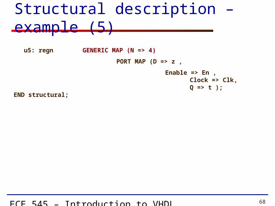
Structural description – example (5)
u5: regn GENERIC MAP (N => 4)
PORT MAP (D => z ,
Enable => En , Clock => Clk, Q => t );END structural;
ECE 545 – Introduction to VHDL 69
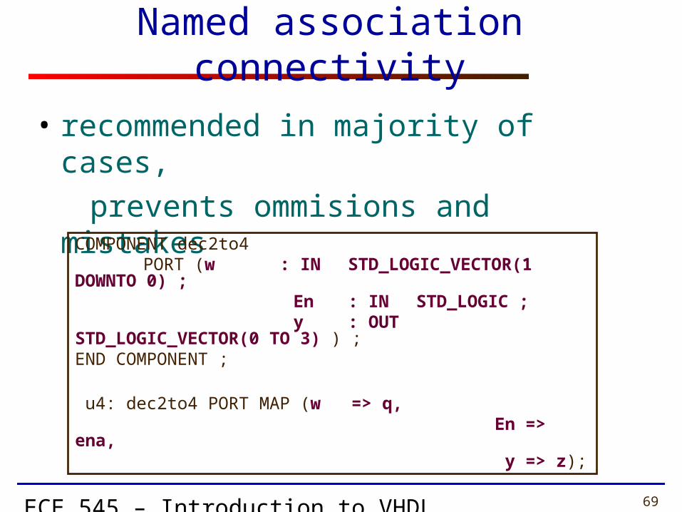
Named association connectivity
• recommended in majority of cases,
prevents ommisions and mistakes
COMPONENT dec2to4PORT (w : IN STD_LOGIC_VECTOR(1
DOWNTO 0) ; En : IN STD_LOGIC ; y : OUT STD_LOGIC_VECTOR(0 TO 3)
) ;END COMPONENT ;
u4: dec2to4 PORT MAP (w => q, En => ena, y => z);

ECE 545 – Introduction to VHDL 70
COMPONENT dec2to4PORT (w : IN STD_LOGIC_VECTOR(1
DOWNTO 0) ; En : IN STD_LOGIC ; y : OUT STD_LOGIC_VECTOR(0 TO 3)
) ;END COMPONENT ;
u4: dec2to4 PORT MAP (w, En, y);
Positional association connectivity
• allowed, especially for the cases of • small number of ports • multiple instantiations of the same component,
in regular structures
ECE 545 – Introduction to VHDL 71
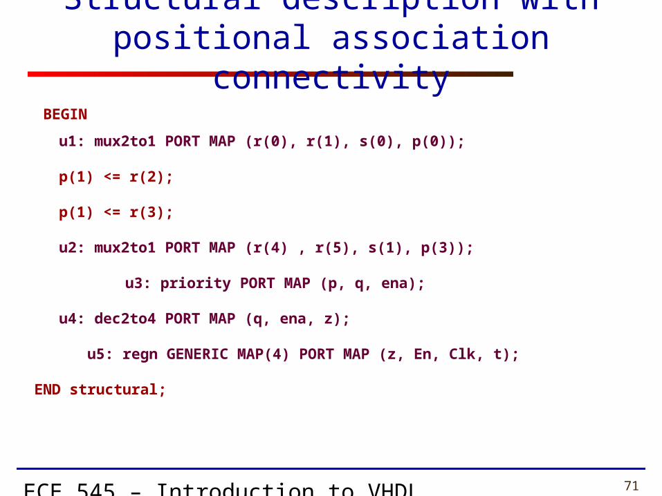
Structural description withpositional association connectivity
BEGIN
u1: mux2to1 PORT MAP (r(0), r(1), s(0), p(0));
p(1) <= r(2);
p(1) <= r(3);
u2: mux2to1 PORT MAP (r(4) , r(5), s(1), p(3));
u3: priority PORT MAP (p, q, ena);
u4: dec2to4 PORT MAP (q, ena, z);
u5: regn GENERIC MAP(4) PORT MAP (z, En, Clk, t);
END structural;

ECE 545 – Introduction to VHDL 72
Packages

ECE 545 – Introduction to VHDL 73
Package – example (1)LIBRARY ieee ;USE ieee.std_logic_1164.all ;
PACKAGE GatesPkg IS
COMPONENT mux2to1PORT (w0, w1, s : IN STD_LOGIC ; f : OUT STD_LOGIC ) ;
END COMPONENT ;
COMPONENT priorityPORT (w : IN STD_LOGIC_VECTOR(3 DOWNTO 0) ;
y : OUT STD_LOGIC_VECTOR(1 DOWNTO 0) ;z : OUT STD_LOGIC ) ;
END COMPONENT ;
ECE 545 – Introduction to VHDL 74
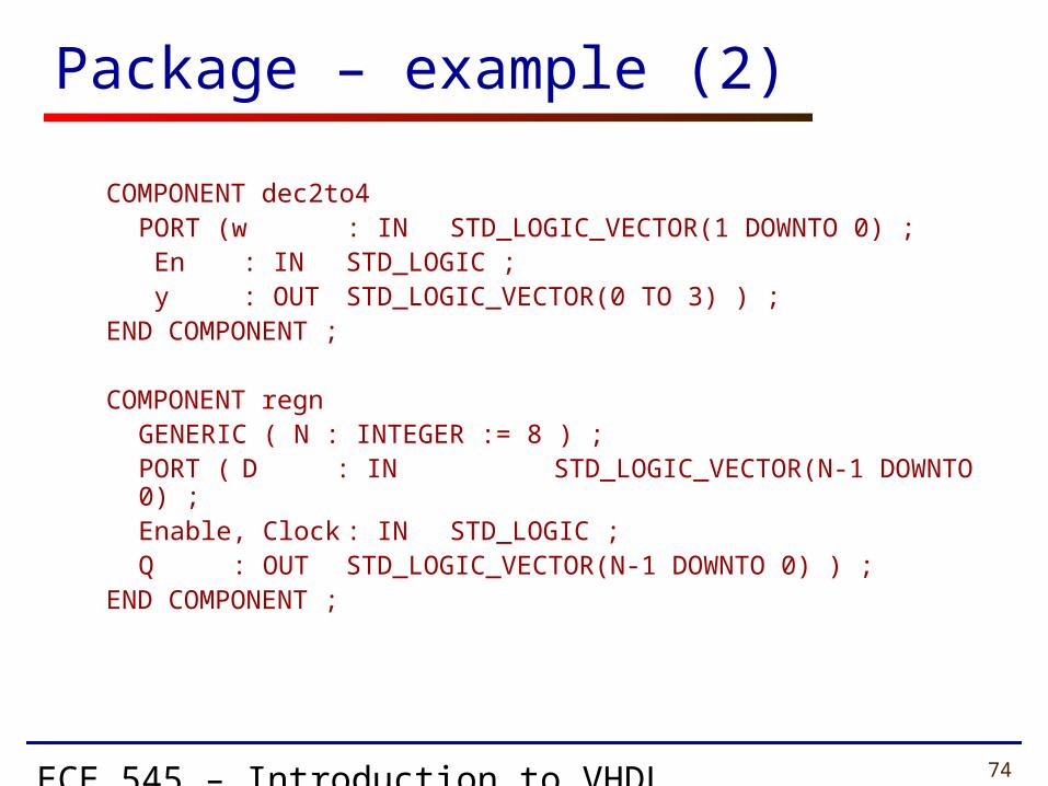
Package – example (2)
COMPONENT dec2to4PORT (w : IN STD_LOGIC_VECTOR(1 DOWNTO 0) ;
En : IN STD_LOGIC ; y : OUT STD_LOGIC_VECTOR(0 TO 3) ) ;
END COMPONENT ;
COMPONENT regnGENERIC ( N : INTEGER := 8 ) ;PORT ( D : IN STD_LOGIC_VECTOR(N-1 DOWNTO 0) ;
Enable, Clock : IN STD_LOGIC ;Q : OUT STD_LOGIC_VECTOR(N-1
DOWNTO 0) ) ;END COMPONENT ;
ECE 545 – Introduction to VHDL 75
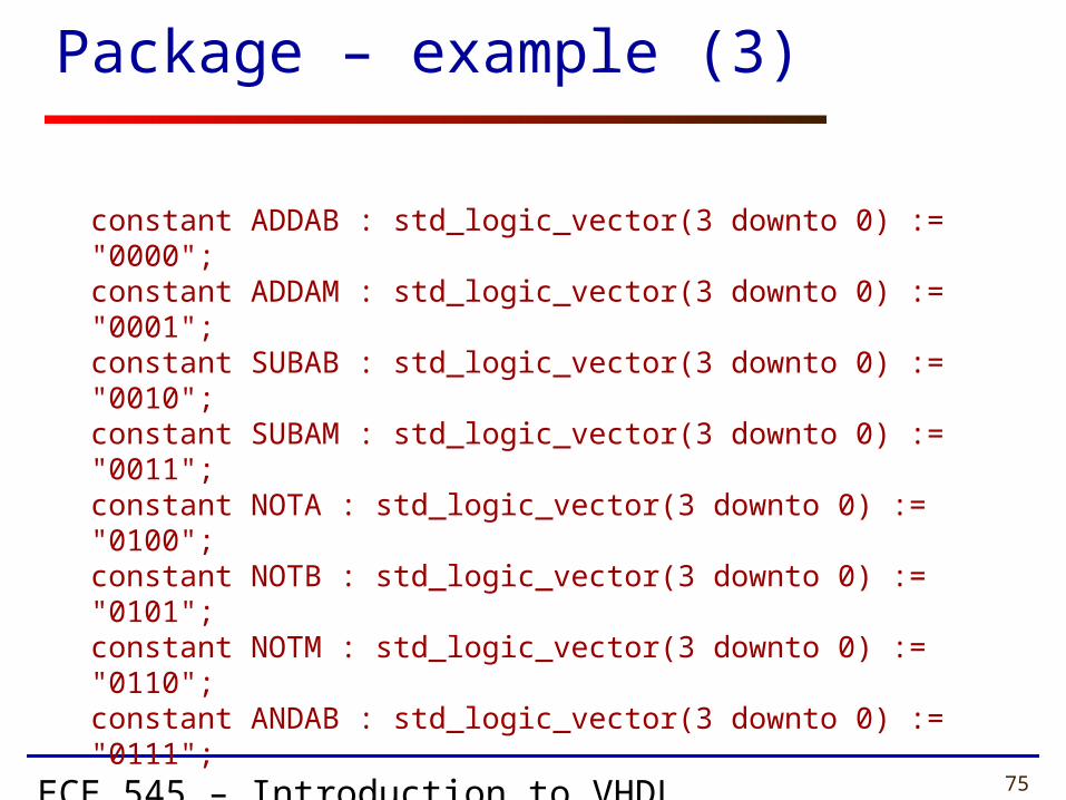
constant ADDAB : std_logic_vector(3 downto 0) := "0000";constant ADDAM : std_logic_vector(3 downto 0) := "0001";constant SUBAB : std_logic_vector(3 downto 0) := "0010";constant SUBAM : std_logic_vector(3 downto 0) := "0011";constant NOTA : std_logic_vector(3 downto 0) := "0100";constant NOTB : std_logic_vector(3 downto 0) := "0101";constant NOTM : std_logic_vector(3 downto 0) := "0110";constant ANDAB : std_logic_vector(3 downto 0) := "0111";
END GatesPkg;
Package – example (3)
ECE 545 – Introduction to VHDL 76
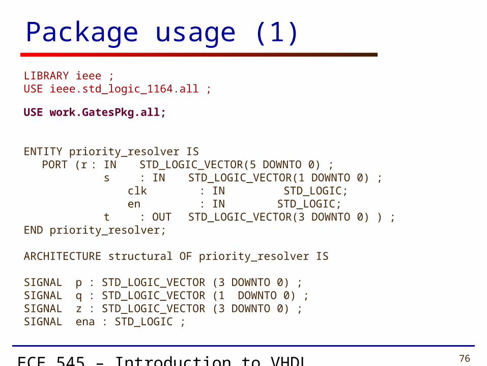
Package usage (1)
LIBRARY ieee ;USE ieee.std_logic_1164.all ;
USE work.GatesPkg.all;
ENTITY priority_resolver ISPORT (r : IN STD_LOGIC_VECTOR(5 DOWNTO 0) ;
s : IN STD_LOGIC_VECTOR(1 DOWNTO 0) ; clk : IN STD_LOGIC; en : IN STD_LOGIC;
t : OUT STD_LOGIC_VECTOR(3 DOWNTO 0) ) ;END priority_resolver;
ARCHITECTURE structural OF priority_resolver IS
SIGNAL p : STD_LOGIC_VECTOR (3 DOWNTO 0) ;SIGNAL q : STD_LOGIC_VECTOR (1 DOWNTO 0) ;SIGNAL z : STD_LOGIC_VECTOR (3 DOWNTO 0) ;SIGNAL ena : STD_LOGIC ;

ECE 545 – Introduction to VHDL 77
BEGIN
u1: mux2to1 PORT MAP (w0 => r(0) , w1 => r(1), s => s(0), f => p(0)); p(1) <= r(2);
p(1) <= r(3);
u2: mux2to1 PORT MAP (w0 => r(4) , w1 => r(5), s => s(1), f => p(3));
u3: priority PORT MAP (w => p, y => q,
z => ena);
u4: dec2to4 PORT MAP (w => q, En => ena, y => z);
Package usage (2)
ECE 545 – Introduction to VHDL 78
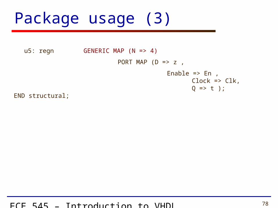
u5: regn GENERIC MAP (N => 4)
PORT MAP (D => z ,
Enable => En , Clock => Clk, Q => t );END structural;
Package usage (3)
ECE 545 – Introduction to VHDL 79
Constants
ECE 545 – Introduction to VHDL 80
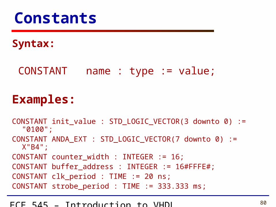
Constants
Syntax:
CONSTANT name : type := value;
Examples:
CONSTANT init_value : STD_LOGIC_VECTOR(3 downto 0) := "0100";CONSTANT ANDA_EXT : STD_LOGIC_VECTOR(7 downto 0) := X"B4";CONSTANT counter_width : INTEGER := 16;CONSTANT buffer_address : INTEGER := 16#FFFE#;CONSTANT clk_period : TIME := 20 ns;CONSTANT strobe_period : TIME := 333.333 ms;
ECE 545 – Introduction to VHDL 81
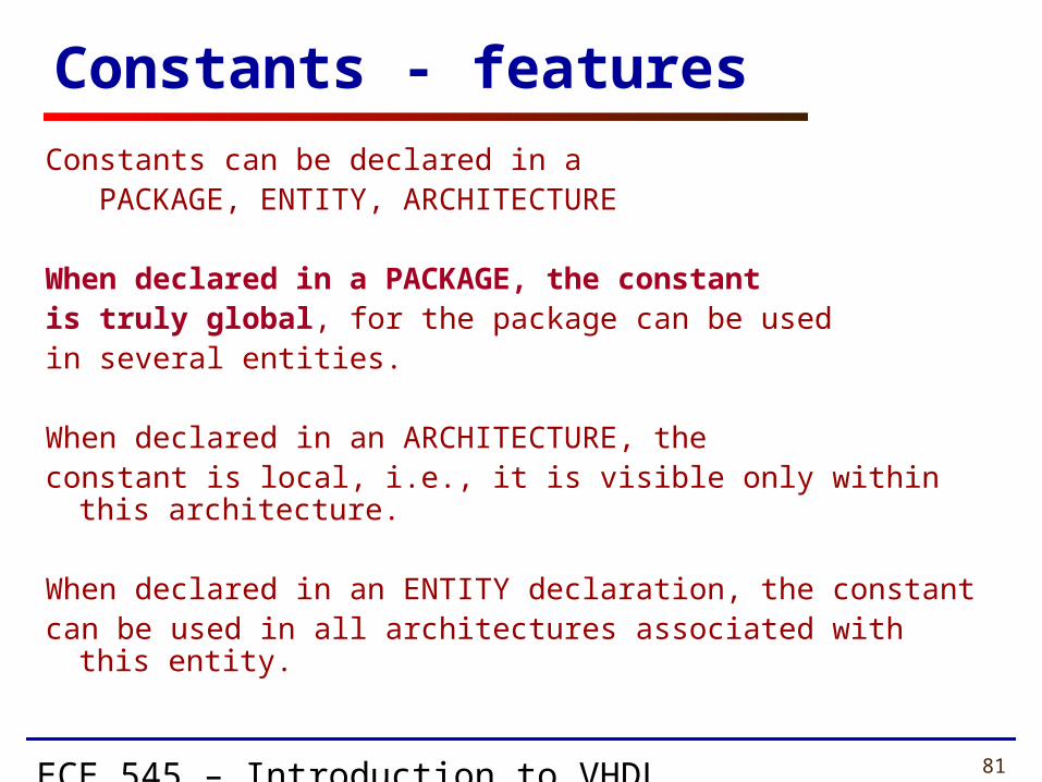
Constants - features
Constants can be declared in a PACKAGE, ENTITY, ARCHITECTURE
When declared in a PACKAGE, the constantis truly global, for the package can be usedin several entities.
When declared in an ARCHITECTURE, theconstant is local, i.e., it is visible only within this architecture.
When declared in an ENTITY declaration, the constant can be used in all architectures associated with this entity.

ECE 545 – Introduction to VHDL 82
Component Configuration
ECE 545 – Introduction to VHDL 83
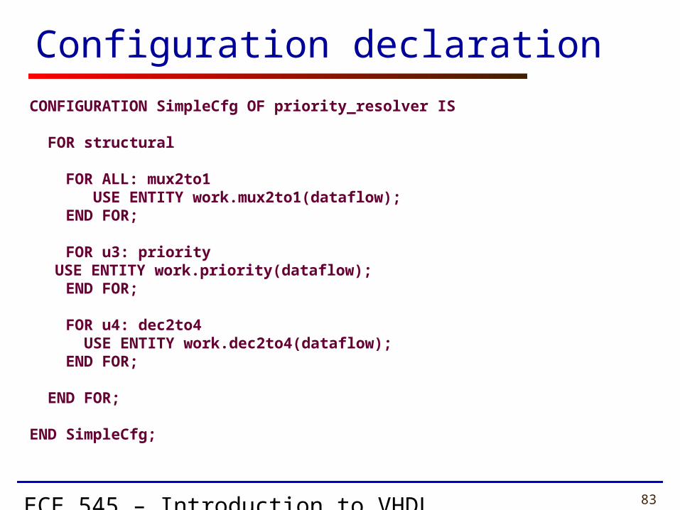
Configuration declaration
CONFIGURATION SimpleCfg OF priority_resolver IS
FOR structural
FOR ALL: mux2to1 USE ENTITY work.mux2to1(dataflow); END FOR;
FOR u3: priority USE ENTITY work.priority(dataflow);
END FOR;
FOR u4: dec2to4 USE ENTITY work.dec2to4(dataflow); END FOR;
END FOR;
END SimpleCfg;
ECE 545 – Introduction to VHDL 84
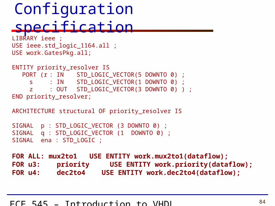
Configuration specificationLIBRARY ieee ;USE ieee.std_logic_1164.all ;USE work.GatesPkg.all;
ENTITY priority_resolver ISPORT (r : IN STD_LOGIC_VECTOR(5 DOWNTO 0) ;
s : IN STD_LOGIC_VECTOR(1 DOWNTO 0) ; z : OUT STD_LOGIC_VECTOR(3 DOWNTO 0) ) ;
END priority_resolver;
ARCHITECTURE structural OF priority_resolver IS
SIGNAL p : STD_LOGIC_VECTOR (3 DOWNTO 0) ;SIGNAL q : STD_LOGIC_VECTOR (1 DOWNTO 0) ;SIGNAL ena : STD_LOGIC ;
FOR ALL: mux2to1 USE ENTITY work.mux2to1(dataflow);FOR u3: priority USE ENTITY work.priority(dataflow);FOR u4: dec2to4 USE ENTITY work.dec2to4(dataflow);

ECE 545 – Introduction to VHDL 85
Mixing Design Styles
Inside of an Architecture

ECE 545 – Introduction to VHDL 86
architecture ARCHITECTURE_NAME of ENTITY_NAME is
• Here you can declare signals, constants, functions, procedures…
• Component declarations• No variable declarations !!
beginConcurrent statements:
• Concurrent simple signal assignment • Conditional signal assignment • Selected signal assignment• Generate statement
• Component instantiation statement
• Process statement• inside process you can use only sequential
statements
end ARCHITECTURE_NAME;
Mixed Style Modeling
Concurrent Statements

ECE 545 – Introduction to VHDL 87
Generate scheme
for components
ECE 545 – Introduction to VHDL 88
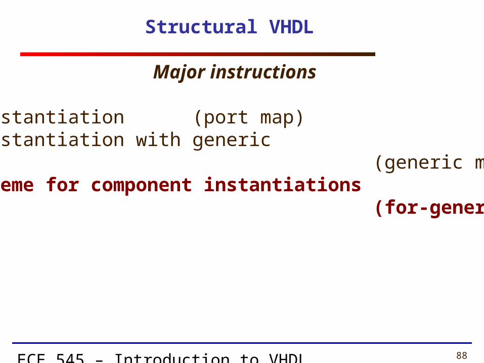
Structural VHDL
• component instantiation (port map)• component instantiation with generic (generic map, port map)• generate scheme for component instantiations (for-generate)
Major instructions
ECE 545 – Introduction to VHDL 89
Example 1
ECE 545 – Introduction to VHDL 90
w 8
w 11
s 1
w 0
s 0
w 3
w 4
w 7
w 12
w 15
s 3
s 2
f
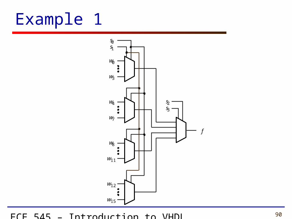
Example 1

ECE 545 – Introduction to VHDL 91
A 4-to-1 Multiplexer
LIBRARY ieee ;USE ieee.std_logic_1164.all ;
ENTITY mux4to1 ISPORT ( w0, w1, w2, w3 : IN STD_LOGIC ;
s : IN STD_LOGIC_VECTOR(1 DOWNTO 0) ;f : OUT STD_LOGIC ) ;
END mux4to1 ;
ARCHITECTURE Dataflow OF mux4to1 ISBEGIN
WITH s SELECTf <= w0 WHEN "00",
w1 WHEN "01", w2 WHEN "10", w3 WHEN OTHERS ;
END Dataflow ;

ECE 545 – Introduction to VHDL 92
Straightforward code for Example 1
LIBRARY ieee ;
USE ieee.std_logic_1164.all ;
ENTITY Example1 IS
PORT ( w : IN STD_LOGIC_VECTOR(0 TO 15) ;
s : IN STD_LOGIC_VECTOR(3 DOWNTO 0) ;
f : OUT STD_LOGIC ) ;
END Example1 ;

ECE 545 – Introduction to VHDL 93
Straightforward code for Example 1
ARCHITECTURE Structure OF Example1 IS
COMPONENT mux4to1PORT ( w0, w1, w2, w3 : IN STD_LOGIC ;
s : IN STD_LOGIC_VECTOR(1 DOWNTO 0) ;
f : OUT STD_LOGIC ) ;END COMPONENT ;
SIGNAL m : STD_LOGIC_VECTOR(0 TO 3) ;
BEGIN
Mux1: mux4to1 PORT MAP ( w(0), w(1), w(2), w(3), s(1 DOWNTO 0), m(0) ) ;
Mux2: mux4to1 PORT MAP ( w(4), w(5), w(6), w(7), s(1 DOWNTO 0), m(1) ) ;
Mux3: mux4to1 PORT MAP ( w(8), w(9), w(10), w(11), s(1 DOWNTO 0), m(2) ) ;
Mux4: mux4to1 PORT MAP ( w(12), w(13), w(14), w(15), s(1 DOWNTO 0), m(3) ) ;
Mux5: mux4to1 PORT MAP ( m(0), m(1), m(2), m(3), s(3 DOWNTO 2), f ) ;
END Structure ;

ECE 545 – Introduction to VHDL 94
Modified code for Example 1
ARCHITECTURE Structure OF Example1 IS
COMPONENT mux4to1
PORT ( w0, w1, w2, w3 : IN STD_LOGIC ;
s : IN STD_LOGIC_VECTOR(1 DOWNTO 0) ;
f : OUT STD_LOGIC ) ;
END COMPONENT ;
SIGNAL m : STD_LOGIC_VECTOR(0 TO 3) ;
BEGIN
G1: FOR i IN 0 TO 3 GENERATE
Muxes: mux4to1 PORT MAP (
w(4*i), w(4*i+1), w(4*i+2), w(4*i+3), s(1 DOWNTO 0), m(i) ) ;
END GENERATE ;
Mux5: mux4to1 PORT MAP ( m(0), m(1), m(2), m(3), s(3 DOWNTO 2), f ) ;
END Structure ;
ECE 545 – Introduction to VHDL 95
Example 2

ECE 545 – Introduction to VHDL 96
Example 2
w 0
En
y 0 w 1 y 1
y 2 y 3
y 8 y 9 y 10y 11
w 2
w 0 y 0 y 1 y 2 y 3
w 0
En
y 0 w 1 y 1
y 2 y 3
w 0
En
y 0 w 1 y 1
y 2 y 3
y 4 y 5 y 6 y 7
w 1
w 0
En
y 0 w 1 y 1
y 2 y 3
y 12y 13y 14y 15
w 0
En
y 0 w 1 y 1
y 2 y 3
w 3
En w

ECE 545 – Introduction to VHDL 97
A 2-to-4 binary decoder
LIBRARY ieee ;USE ieee.std_logic_1164.all ;
ENTITY dec2to4 ISPORT ( w : IN STD_LOGIC_VECTOR(1 DOWNTO 0) ;
En : IN STD_LOGIC ; y : OUT STD_LOGIC_VECTOR(0 TO 3) ) ;
END dec2to4 ;
ARCHITECTURE Dataflow OF dec2to4 ISSIGNAL Enw : STD_LOGIC_VECTOR(2 DOWNTO 0) ;
BEGINEnw <= En & w ;WITH Enw SELECT
y <= "1000" WHEN "100", "0100" WHEN "101",
"0010" WHEN "110", "0001" WHEN "111",
"0000" WHEN OTHERS ;END Dataflow ;

ECE 545 – Introduction to VHDL 98
VHDL code for Example 2 (1)
LIBRARY ieee ;
USE ieee.std_logic_1164.all ;
ENTITY dec4to16 IS
PORT (w : IN STD_LOGIC_VECTOR(3 DOWNTO 0) ;
En : IN STD_LOGIC ;
y : OUT STD_LOGIC_VECTOR(0 TO 15) ) ;
END dec4to16 ;
ECE 545 – Introduction to VHDL 99
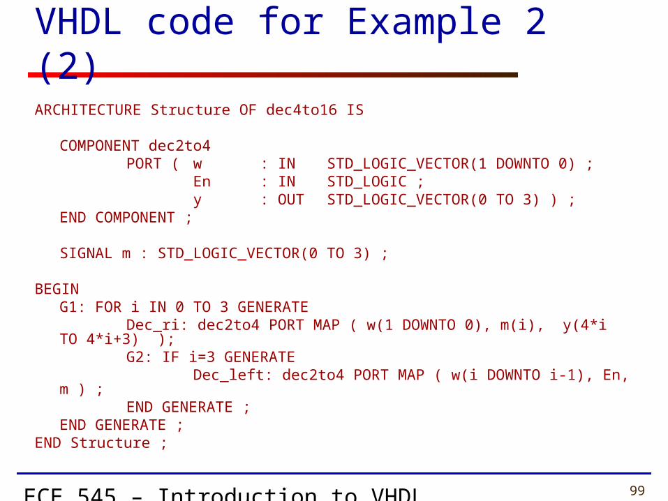
VHDL code for Example 2 (2)
ARCHITECTURE Structure OF dec4to16 IS
COMPONENT dec2to4PORT ( w : IN STD_LOGIC_VECTOR(1 DOWNTO 0) ;
En : IN STD_LOGIC ;y : OUT STD_LOGIC_VECTOR(0 TO 3) ) ;
END COMPONENT ;
SIGNAL m : STD_LOGIC_VECTOR(0 TO 3) ;
BEGING1: FOR i IN 0 TO 3 GENERATE
Dec_ri: dec2to4 PORT MAP ( w(1 DOWNTO 0), m(i), y(4*i TO 4*i+3) );G2: IF i=3 GENERATE
Dec_left: dec2to4 PORT MAP ( w(i DOWNTO i-1), En, m ) ;END GENERATE ;
END GENERATE ;END Structure ;
ECE 545 – Introduction to VHDL 100
Example 3Variable Rotator

ECE 545 – Introduction to VHDL 101
Example 3: Variable rotator - Interface
16
16
4
A
B
C
A <<< B
ECE 545 – Introduction to VHDL 102
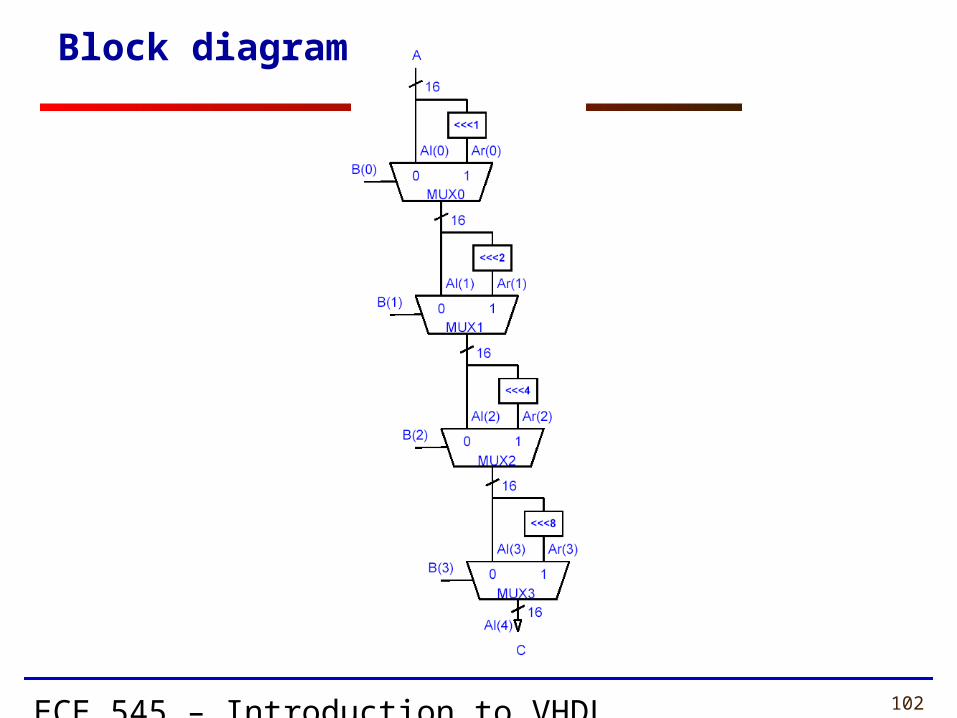
Block diagram
ECE 545 – Introduction to VHDL 103
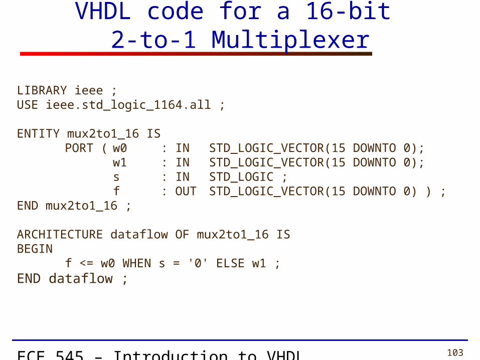
VHDL code for a 16-bit 2-to-1 Multiplexer
LIBRARY ieee ;USE ieee.std_logic_1164.all ;
ENTITY mux2to1_16 ISPORT ( w0 : IN STD_LOGIC_VECTOR(15 DOWNTO 0);
w1 : IN STD_LOGIC_VECTOR(15 DOWNTO 0);s : IN STD_LOGIC ;f : OUT STD_LOGIC_VECTOR(15 DOWNTO 0) ) ;
END mux2to1_16 ;
ARCHITECTURE dataflow OF mux2to1_16 ISBEGIN
f <= w0 WHEN s = '0' ELSE w1 ;END dataflow ;

ECE 545 – Introduction to VHDL 104
Fixed rotation
a(15) a(14) a(13) a(12) a(11) a(10) a(9) a(8) a(7) a(6) a(5) a(4) a(3) a(2) a(1) a(0)
a(12) a(11) a(10) a(9) a(8) a(7) a(6) a(5) a(4) a(3) a(2) a(1) a(0) a(15) a(14) a(13)
<<< 3
a(15) a(14) a(13) a(12) a(11) a(10) a(9) a(8) a(7) a(6) a(5) a(4) a(3) a(2) a(1) a(0)
a(10) a(9) a(8) a(7) a(6) a(5) a(4) a(3) a(2) a(1) a(0) a(15) a(14) a(13) a(12) a(11)
<<< 5
ECE 545 – Introduction to VHDL 105
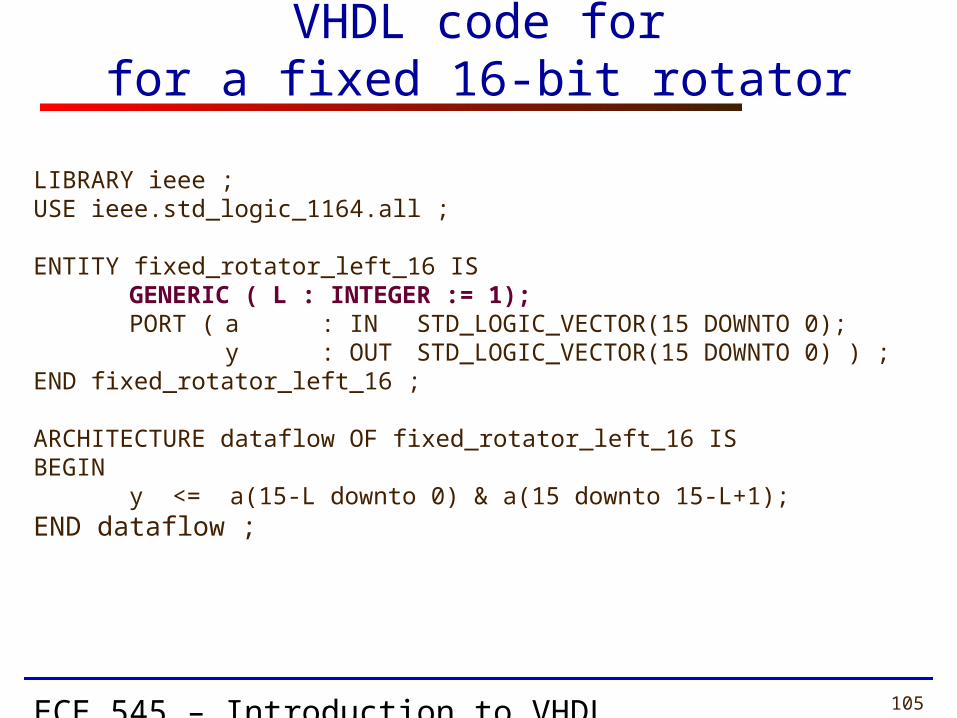
VHDL code forfor a fixed 16-bit rotator
LIBRARY ieee ;USE ieee.std_logic_1164.all ;
ENTITY fixed_rotator_left_16 ISGENERIC ( L : INTEGER := 1);PORT ( a : IN STD_LOGIC_VECTOR(15 DOWNTO 0);
y : OUT STD_LOGIC_VECTOR(15 DOWNTO 0) ) ;END fixed_rotator_left_16 ;
ARCHITECTURE dataflow OF fixed_rotator_left_16 ISBEGIN
y <= a(15-L downto 0) & a(15 downto 15-L+1);END dataflow ;
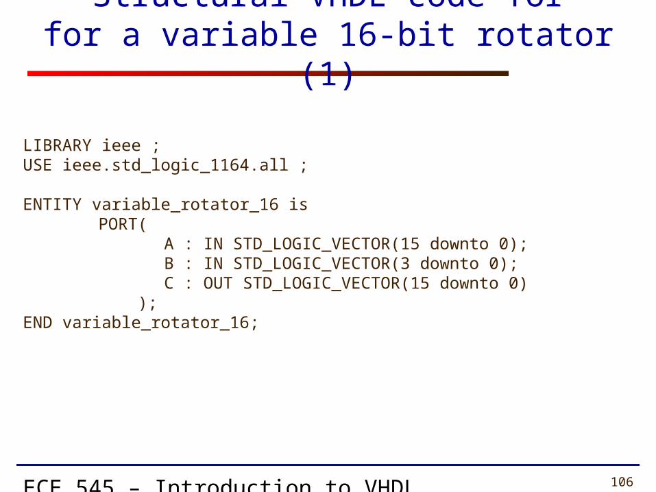
ECE 545 – Introduction to VHDL 106
Structural VHDL code forfor a variable 16-bit rotator (1)
LIBRARY ieee ;USE ieee.std_logic_1164.all ;
ENTITY variable_rotator_16 is PORT(
A : IN STD_LOGIC_VECTOR(15 downto 0); B : IN STD_LOGIC_VECTOR(3 downto 0); C : OUT STD_LOGIC_VECTOR(15 downto 0)
);END variable_rotator_16;

ECE 545 – Introduction to VHDL 107
Structural VHDL code forfor a variable 16-bit rotator (2)
LIBRARY ieee ;USE ieee.std_logic_1164.all ;
ARCHITECTURE structural OF variable_rotator_16 IS
COMPONENT mux2to1_16PORT ( w0 : IN STD_LOGIC_VECTOR(15 DOWNTO 0);
w1 : IN STD_LOGIC_VECTOR(15 DOWNTO 0);s : IN STD_LOGIC ;f : OUT STD_LOGIC_VECTOR(15 DOWNTO 0) ) ;
END COMPONENT ;
COMPONENT fixed_rotator_left_16GENERIC ( L : INTEGER := 1);PORT ( a : IN STD_LOGIC_VECTOR(15 DOWNTO 0);
y : OUT STD_LOGIC_VECTOR(15 DOWNTO 0) ) ; END COMPONENT ;

ECE 545 – Introduction to VHDL 108
Structural VHDL code forfor a variable 16-bit rotator (3)
TYPE array1 IS ARRAY (0 to 4) OF STD_LOGIC_VECTOR(15 DOWNTO 0);TYPE array2 IS ARRAY (0 to 3) OF STD_LOGIC_VECTORS(15 DOWNTO 0);SIGNAL Al : array1;SIGNAL Ar : array2;
BEGINAl(0) <= A;G: FOR i IN 0 TO 3 GENERATE ROT_I: fixed_rotator_left_16
GENERIC MAP (L => 2** i) PORT MAP ( a => Al(i) ,
y => Ar(i)); MUX_I: mux2to1_16 PORT MAP (w0 => Al(i),
w1 => Ar(i), s => B(i), f => Al(i+1));
END GENERATE;C <= Al(4);
END variable_rotator_16;

ECE 545 – Introduction to VHDL 109
Example 4N-bit Comparator
ECE 545 – Introduction to VHDL 110
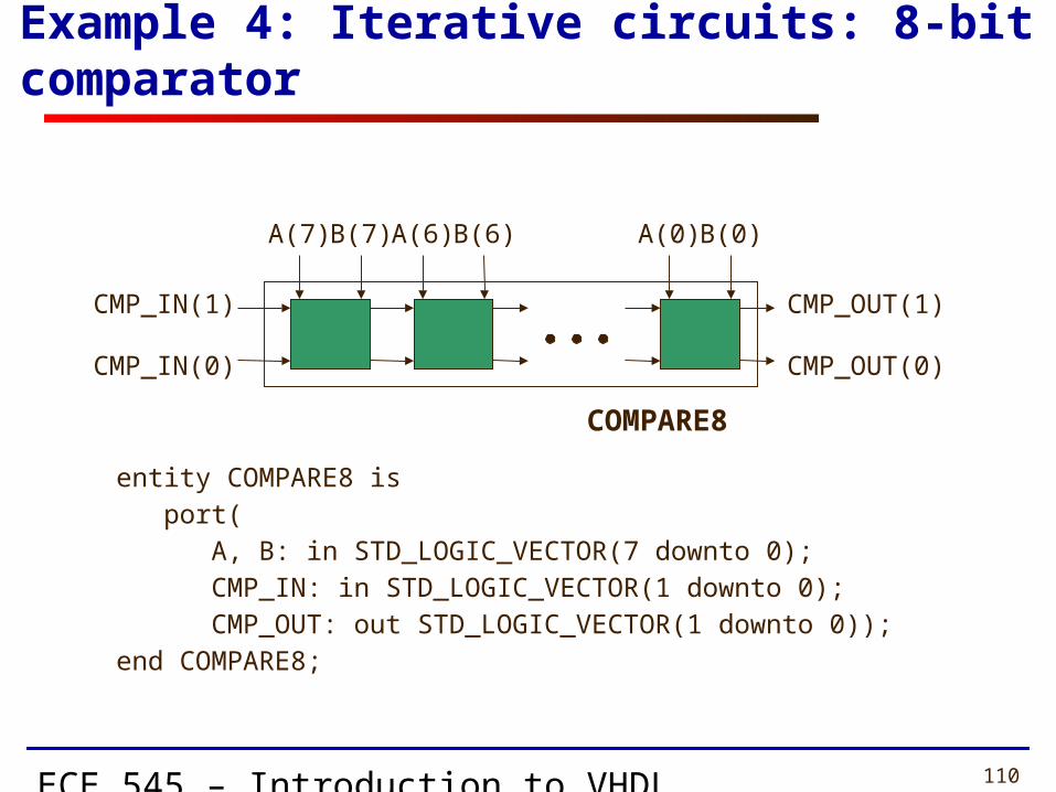
Example 4: Iterative circuits: 8-bit comparator
A(7) B(7)
CMP_IN(1)
CMP_IN(0)
A(6) B(6) A(0) B(0)
CMP_OUT(1)
CMP_OUT(0)
entity COMPARE8 is port( A, B: in STD_LOGIC_VECTOR(7 downto 0); CMP_IN: in STD_LOGIC_VECTOR(1 downto 0); CMP_OUT: out STD_LOGIC_VECTOR(1 downto 0));end COMPARE8;
COMPARE8
ECE 545 – Introduction to VHDL 111
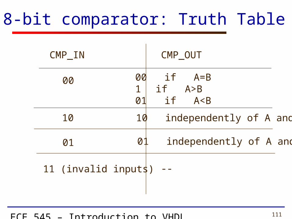
8-bit comparator: Truth Table
CMP_IN CMP_OUT
00 00 if A=B1 if A>B01 if A<B
10 10 independently of A and B
01 01 independently of A and B
11 (invalid inputs) --
ECE 545 – Introduction to VHDL 112
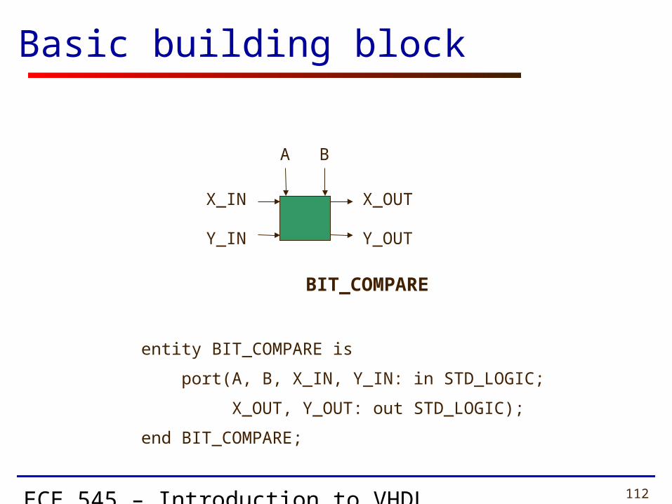
A B
X_OUT
Y_OUT
BIT_COMPARE
entity BIT_COMPARE is
port(A, B, X_IN, Y_IN: in STD_LOGIC;
X_OUT, Y_OUT: out STD_LOGIC);
end BIT_COMPARE;
X_IN
Y_IN
Basic building block

ECE 545 – Introduction to VHDL 113
X_IN & Y_IN X_OUT & Y_OUT
00 00 if A=B1 if A=‘1’ and B=‘0’01 if A=‘0’ and B=‘1’
10 10 independently of A and B
01 01 independently of A and B
11 (invalid inputs) --
Basic building block – Truth Table

ECE 545 – Introduction to VHDL 114
8-bit comparator - Architecture
A(7) B(7)
CMP_IN(1)
CMP_IN(0)
A(6) B(6) A(0) B(0)
CMP_OUT(1)
CMP_OUT(0)
INT_X(7) INT_X(1)
INT_Y(7) INT_Y(1)
INT_X(6)
INT_Y(6)
ECE 545 – Introduction to VHDL 115
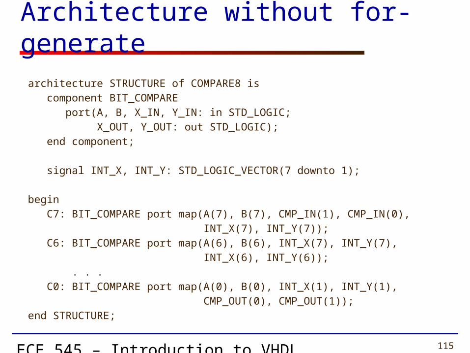
architecture STRUCTURE of COMPARE8 is component BIT_COMPARE port(A, B, X_IN, Y_IN: in STD_LOGIC; X_OUT, Y_OUT: out STD_LOGIC); end component;
signal INT_X, INT_Y: STD_LOGIC_VECTOR(7 downto 1);
begin C7: BIT_COMPARE port map(A(7), B(7), CMP_IN(1), CMP_IN(0), INT_X(7), INT_Y(7)); C6: BIT_COMPARE port map(A(6), B(6), INT_X(7), INT_Y(7), INT_X(6), INT_Y(6)); . . . C0: BIT_COMPARE port map(A(0), B(0), INT_X(1), INT_Y(1), CMP_OUT(0), CMP_OUT(1));end STRUCTURE;
Architecture without for-generate
ECE 545 – Introduction to VHDL 116
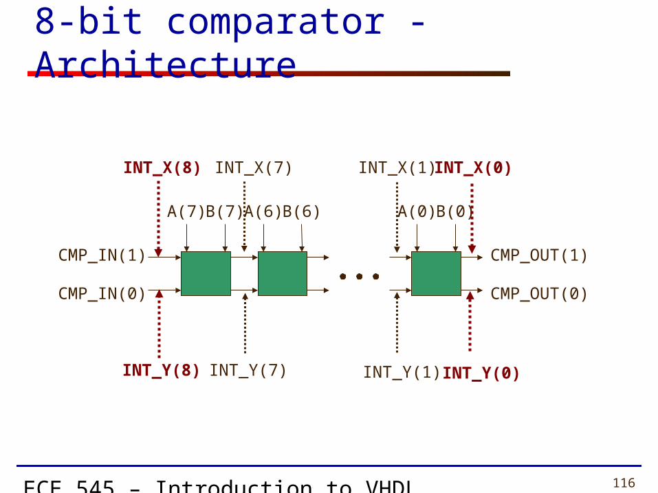
8-bit comparator - Architecture
A(7) B(7)
CMP_IN(1)
CMP_IN(0)
A(6) B(6) A(0) B(0)
CMP_OUT(1)
CMP_OUT(0)
INT_X(7) INT_X(1)
INT_Y(7) INT_Y(1)
INT_X(8)
INT_Y(8)
INT_X(0)
INT_Y(0)
ECE 545 – Introduction to VHDL 117
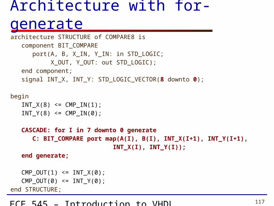
architecture STRUCTURE of COMPARE8 is component BIT_COMPARE port(A, B, X_IN, Y_IN: in STD_LOGIC; X_OUT, Y_OUT: out STD_LOGIC); end component; signal INT_X, INT_Y: STD_LOGIC_VECTOR(8 downto 0);
begin INT_X(8) <= CMP_IN(1); INT_Y(8) <= CMP_IN(0);
CASCADE: for I in 7 downto 0 generate C: BIT_COMPARE port map(A(I), B(I), INT_X(I+1), INT_Y(I+1), INT_X(I), INT_Y(I)); end generate;
CMP_OUT(1) <= INT_X(0); CMP_OUT(0) <= INT_Y(0);end STRUCTURE;
Architecture with for-generate

ECE 545 – Introduction to VHDL 118
N-bit Comparator – Entity declaration
entity COMPAREN is generic(N: positive); -- N – width of operands port( A, B: in BIT_VECTOR(N-1 downto 0); CMP_IN: in BIT_VECTOR(1 downto 0); CMP_OUT: out BIT_VECTOR(1 downto 0));end COMPAREN;

ECE 545 – Introduction to VHDL 119
architecture STRUCTURE of COMPAREN is component BIT_COMPARE port(A, B, X_IN, Y_IN: in STD_LOGIC; X_OUT, Y_OUT: out STD_LOGIC); end component; signal INT_X, INT_Y: STD_LOGIC_VECTOR(N downto 0);begin INT_X(N) <= CMP_IN(1); INT_Y(N) <= CMP_IN(0);
CASCADE: for I in N-1 downto 0 generate C: BIT_COMPARE port map(A(I), B(I), INT_X(I+1), INT_Y(I+1), INT_X(I), INT_Y(I)); end generate;
CMP_OUT(1) <= INT_X(0); CMP_OUT(0) <= INT_Y(0);end STRUCTURE;
N-bit Comparator – Architecture
ECE 545 – Introduction to VHDL 120
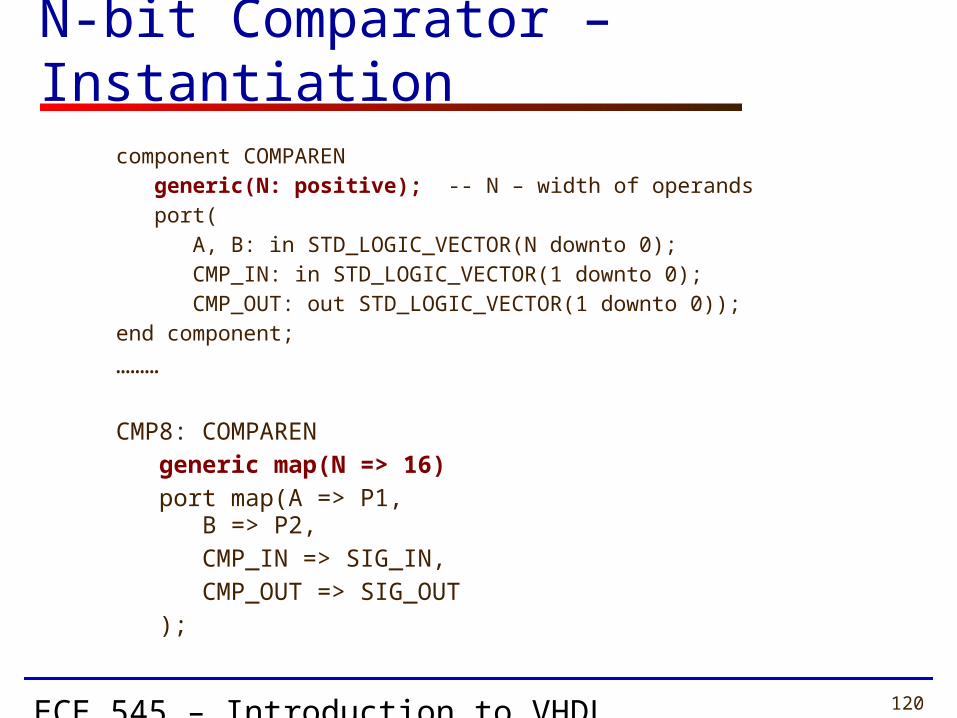
component COMPAREN generic(N: positive); -- N – width of operands port( A, B: in STD_LOGIC_VECTOR(N downto 0); CMP_IN: in STD_LOGIC_VECTOR(1 downto 0); CMP_OUT: out STD_LOGIC_VECTOR(1 downto 0));end component;
………
CMP8: COMPAREN generic map(N => 16) port map(A => P1, B => P2, CMP_IN => SIG_IN, CMP_OUT => SIG_OUT );
N-bit Comparator – Instantiation


