Global Truss user instructions----ST-180 light stand 1 1. INTRODUCTION Thank you for choosing a light stand system from Global Truss. This stand has been specially designed to have a very low loading height obtained by a multi-mast configuration. The telescopic masts made of treated steel have been generously sized in order to obtain maximum rigidity, special attention has been placed on security. The ABS (AUTOPIN BLOCKING SYSTEM) guaranties double security in lifting or operational position, additionally as a third safety device, each mast can be secured with a locking knob. 2. TECHNICAL DATA All models are equipped with: A: 4 castors for horizontal transport B: Wide and stable metal base C: Nylon guided leg sliders D: Independent adjustable leg braces E: Auto-leveling galvanized foot plates with attachment holes F: Solid wide legs for extra stability G: Large locking knobs 3rd safety device H: Protected manual winch with safety friction brake I: AUTOPIN BLOCKING SYSTEM J: 4 castors for vertical movement Lateral play compensation with the masts Spirit level Friction surfaces on nylon sliders All cable pulleys maintenance are free A B C D E F G H I J A
Transcript
Global Truss user instructions----ST-180 light stand
Page 1
1. INTRODUCTION
Thank you for choosing a light stand system from Global Truss.
This stand has been specially designed to have a very low loading
height obtained by a multi-mast configuration.
The telescopic masts made of treated steel have been generously
sized in order to obtain maximum rigidity, special attention has
been placed on security.
The ABS (AUTOPIN BLOCKING SYSTEM) guaranties
double security in lifting or operational position, additionally as a
third safety device, each mast can be secured with a locking knob.
2. TECHNICAL DATA
All models are equipped with:
A: 4 castors for horizontal transport
B: Wide and stable metal base
C: Nylon guided leg sliders
D: Independent adjustable leg braces
E: Auto-leveling galvanized foot plates with attachment holes
F: Solid wide legs for extra stability
G: Large locking knobs((((3rd safety device ))))
H: Protected manual winch with safety friction brake
I: AUTOPIN BLOCKING SYSTEM
J: 4 castors for vertical movement
� Lateral play compensation with the masts
� Spirit level
� Friction surfaces on nylon sliders
� All cable pulleys maintenance are free
A
B
C
D
E
F
G
H
I
J
A
Global Truss user instructions----ST-180 light stand
Page 2
Technical date
3. POSITIONING THE STAND
1): Place the stand in the vertical position on its wheels (J).
2): Ensure that the ground in strong enough to prevent any sinking
of the stand into the ground. The stability of the stand is of
prime importance for a secure operation.
3): Pull out the spring pin (K), and screw out the screw handle (L)
to unlock the leg-brace slider(C) and flip the leg (F) from
vertical into horizontal position.
4): Choose the closest of the holes in the leg (F) and restore the
spring pin (K) and the screw handle (L) to lock the leg-brace
slider(C) to the leg (F).
5): Repeat step 3) and 4) with the other 3 legs.
6): Use the leg-brace screw jacks (D) to ensure the footplate (E)
touches the ground.
7): Continue turning the screw jacks (D) of each leg in sequence
until the wheels (J) slightly lift off the ground (5-10mm is
recommended).
8): When used on a sloping surface, the footplates (E) must be
secured to the ground to avoid any sliding.
9): When the stand in securely positioned and vertical, check again
that the leg-brace sliders (C) are properly locked into their holes
in the foot (F).
ST-180
Maximum load: 180kg 450lb.
Maximum height: 5.5m 18`0”
Minimum height: 1.77m 5`1”
Footprint: 2.17m 7`2”
Weight: 104kg 229lb
Closed size: 1.77m 5`1”
Material: treated steel
Finish: Epoxy black painting / electro-galvanized
L
D
K
C
E
Global Truss user instructions----ST-180 light stand
Page 3
4. LIFTING THE MASTS
1): Loosen the top locking knob (G) of the top telescopic mast
(smallest).
2): Tighten the other locking knobs to ensure a proper lifting order.
The top-mast (smallest) has to raise first, followed by the
bigger mast below in sequence.
3): Pull the ABS (AUTOPIN BLOCKING SYSTEM (I))’s ring to
unlock the top telescopic mast (smallest).
4): Turn the winch crank (H) clockwise to raise the top-mast. When
the desired position is reaching, release the ABS’ ring; make
sure that the ABS’ auto pins have gone into its desired hole. If
you are in its maximum height, it will block itself.
5): Tighten the top locking knob (G) to secure the mast and to
avoid any lateral movement.
6): Repeat steps with the other masts.
7): Turn the winch crank (H) anti-clockwise a little to avoid the
cable to support any load.
8): You can add the load as long as all the ABS (AUTOPIN
BLOCKING SYSTEM (I)) are in place and the locking knobs
(G) are tightened against its masts and the cable is avoided to
support the load.
G I
H
Global Truss user instructions----ST-180 light stand
Page 4
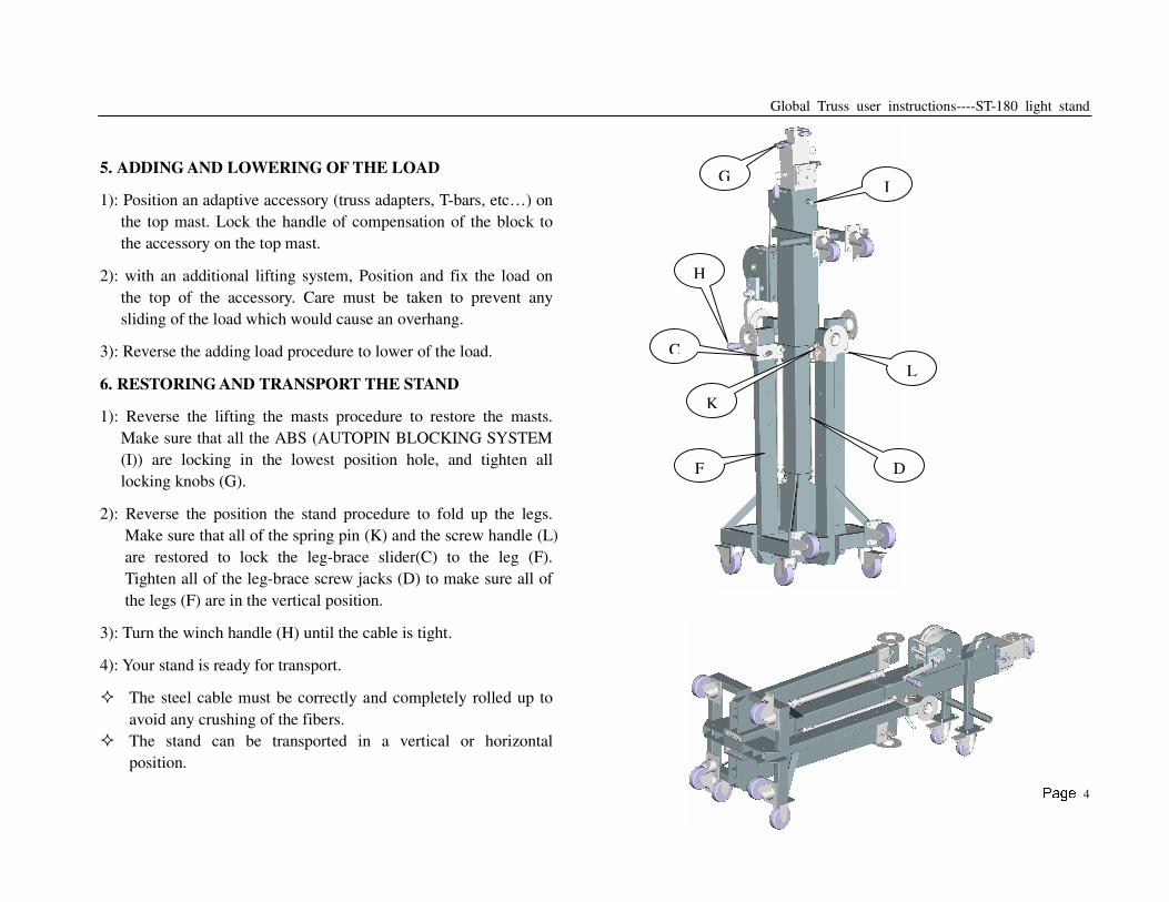
5. ADDING AND LOWERING OF THE LOAD
1): Position an adaptive accessory (truss adapters, T-bars, etc…) on
the top mast. Lock the handle of compensation of the block to
the accessory on the top mast.
2): with an additional lifting system, Position and fix the load on
the top of the accessory. Care must be taken to prevent any
sliding of the load which would cause an overhang.
3): Reverse the adding load procedure to lower of the load.
6. RESTORING AND TRANSPORT THE STAND
1): Reverse the lifting the masts procedure to restore the masts.
Make sure that all the ABS (AUTOPIN BLOCKING SYSTEM
(I)) are locking in the lowest position hole, and tighten all
locking knobs (G).
2): Reverse the position the stand procedure to fold up the legs.
Make sure that all of the spring pin (K) and the screw handle (L)
are restored to lock the leg-brace slider(C) to the leg (F).
Tighten all of the leg-brace screw jacks (D) to make sure all of
the legs (F) are in the vertical position.
3): Turn the winch handle (H) until the cable is tight.
4): Your stand is ready for transport.
� The steel cable must be correctly and completely rolled up to
avoid any crushing of the fibers.
� The stand can be transported in a vertical or horizontal
position.
I
K
L
C
F D
H
G
Global Truss user instructions----ST-180 light stand
Page 5
7. IMPORTANT WARNING!
1): Respect the factory guidelines concerning the load limits as well
as the safety codes of material and staff. The choice of trussing
and the stand capacity must be adapted to the load.
2): Adequate safety measures must be taken when people work
under the loads carried by the truss and the stands, safety steel
slings and chains must be used on every item hung on the truss.
3): The operator must take into account the weight of the holding
truss on the stand and deduct it from its allowable load.
4): All electrical devices hung on the stand or by the stand must
absolutely conform to the technical codes concerning electrical
devices (EC NORMS).
5): The stand must only be operated in an exactly vertical position.
6): Secure the stand to the ground when it’s used on a sloping
surface.
7): Load the stand using only adaptive accessories.
8): The load must be centered or evenly distributed on the stand, be
careful that the load does not slide to avoid any overhang of the
load.
9): Never let the cable only support the entire load.
10): Always use all three load holding systems.
11): Never move the stand when it is loaded.
12): Never use the stand to carry people.
13): Never lean a ladder on the stand.
14): Never lubricate the winch brake.
15): Never exceed the allowed load limits.
16): Never use the stand in outdoor in typhoon weather condition.
17): It is dangerous to support a very big size load in windy
outdoor condition.
18): Do not allow the stand to be used on a soft or moveable
surface.
19): All sliding and rotating mechanisms used in bad weather must
be regularly lubricated.
20): The annual control of the elevator by an authorized person is
compulsory.
Global Truss user instructions----ST-180 light stand
Page 6
8. THE RESPONSIBILITY OF THE FAULT
1): The use of trussing and lifting equipment in temporary or
mobile installation is the sole responsibility of the operator.
2): During the guarantee period, we or one of our contract service
organizations undertake to repair, free of charge any damage
attributable to faulty materials or workmanship for a period of
12 month after date of purchase.
3): The guarantee does not cover damage due to negligent handling,
overload or parts subject to normal wear and tear.
4): The fitting of replacement parts not supplied by us or
modifications of our design by third parties invalidates the
guarantee.
GUARANTEE CERTIFICATE
for
12 Month Guarantee
Type of appliance:
Serial Number:
Purchase Date:
Name:
Address:
City: Postcode:
Country:
Phone: Fax:
E-Mail:
Distributed by:
During the guarantee period, we undertake to repair, free of charge
any damage attributable to faulty materials or workmanship, for a
period of 12 month after date of purchase provided that the unit is
forwarded, freight paid, to our works or one of our contract service
centers. The guarantee does not cover damage due to negligent
handling, overload or parts subject to normal wear and tear. The
fitting of replacement parts not supplied by us or modifications of
our design by third parties also invalidates the guarantee. In case of
a claim under the guarantee, please attach this voucher and
purchase receipt after entering the unit No. in the space above.