Dati tecnici (1) Prevedere due tubi flessibili (2) Per pressioni superiori a 5 bar installare un riduttore di pressione a monte della tubatura. (3) Per garantire il corretto funzionamento la temperatura dell’acqua deve essere di 50°C (1) To foresse two flexible pipes. (2) If the water pressure exceeds 5 bars, a pressure reducer should be fitted upstream from the feed pipe. (3) To ensure proper operation, minimum water temperature shouldbe set to 50°C. Voltage Frequency Total power absorption Max current Cold and hot water fittings (1) Waste trap Power cable Equipotent. cable Operatin pressure (2) Water delivery Dynamic pressure Net weigth (±5 kg) Cold water temperature Hotd water temperature (3) Technical data Tensione V~ Frequenza Hz Potenza assorbita totale W Corrente massima A Allaccio acqua fred. e calda (1) Scarico ø mm Cavo alimentazione mt Cavo equipotenziale mt Pressione di rete (2) atm Portata acqua l/min Pressione dinamica bar Peso netto (±5 kg) kg Temperatura acqua fredda °C Temperatura acqua calda (3) °C CABINA MULTIFUNZIONE MULTIFUNCTION CABIN L’immagine rappresenta l’installazione SINISTRA. “CABINA DOCCIA REVERSIBILE”. Picture represents left installation. “REVERSIBLE MULTIFUNCTION SHOWER” Scheda tecnica di “Pre-Installazione” “Pre-Installation” technical sheet Nr. Dimensioni “cm” tolleranza ±5mm Dimensions “cm” tolerance ±5mm Ed. 01- 02/2021 VAPOR K750 Nr. corner 1-K750 Ed. 01- 02/2021 4,5 cm - senza piedini 12 cm - con piedini 208,5 senza piedini without feet 213 con piedini 80 80 ___ ___ min. 50 without feet with feet with feet erogatore vapore steam dispenser generatore di vapore steam generator 230~ 50 3000 12 1/2” 40 2 2 1÷5 8÷13 2 80 5÷25 50÷80 80x80 corner K750 corner
Transcript
Dati tecnici
(1) Prevedere due tubi flessibili(2) Per pressioni superiori a 5 bar installare un riduttore di pressione a
monte della tubatura.(3) Per garantire il corretto funzionamento la temperatura dell’acqua
deve essere di 50°C
(1) To foresse two flexible pipes.(2) If the water pressure exceeds 5 bars, a pressure reducer should be
fitted upstream from the feed pipe.(3) To ensure proper operation, minimum water temperature shouldbe
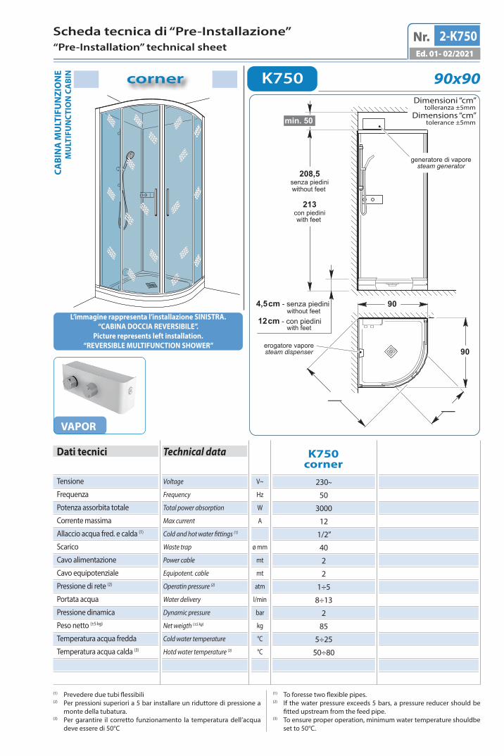
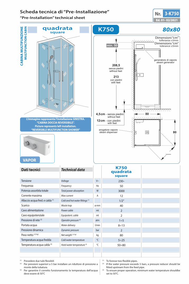
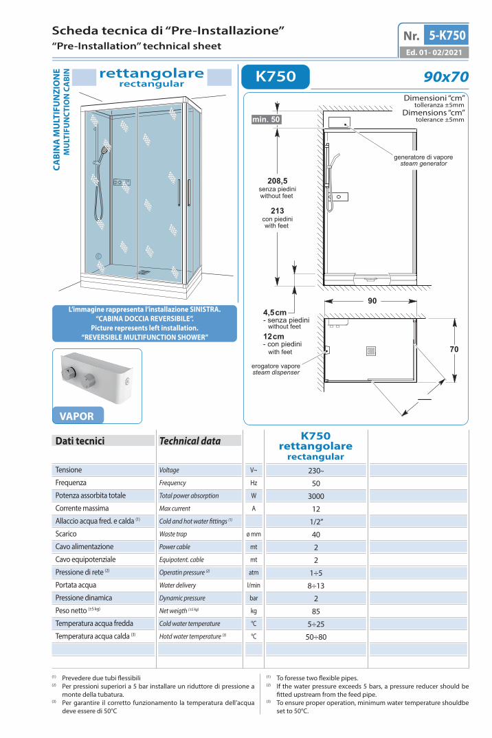
Picture represents left installation.“REVERSIBLE MULTIFUNCTION SHOWER”
Scheda tecnica di “Pre-Installazione”“Pre-Installation” technical sheet
Nr.
Dimensioni “cm”tolleranza ±5mm
Dimensions “cm”tolerance ±5mm
Ed. 01- 02/2021
VAPOR
K750
Nr.
corner
1-K750Ed. 01- 02/2021
4,5 cm - senza piedini
12 cm - con piedini
208,5senza piediniwithout feet
213con piedini
80
80
______
min. 50
without feet
with feet
with feet
erogatore vaporesteam dispenser
generatore di vaporesteam generator
230~
50
3000
12
1/2”
40
2
2
1÷5
8÷13
2
80
5÷25
50÷80
80x80corner
K750corner
I dat
i e le
car
atte
rist
iche
indi
cate
non
impe
gnan
o la
SFA
S.p
.A.,
che
si r
iser
va il
dir
itto
di a
ppor
tare
tut
te le
mod
ifich
e ri
tenu
te o
ppor
tune
sen
za o
bblig
o di
pre
avvi
so o
sos
titu
zion
e
!!! IL COSTRUTTORE NON E’ RESPONSABILE PER I DANNI DOVUTI AD UNA ERRATA O NON CONFORME INSTALLAZIONE.IN NO EVENT SHALL THE MANUFACTURER BE LIABLE FOR ANY DAMAGES WHATSOEVER THAT MAY ARISE FROM INAPPROPRIATE AND NON-COMPLIANT INSTALLATION PROCEDURES.
Neith
er th
e in
form
atio
n no
r the
char
acte
ristic
s rep
orte
d ar
e bi
ndin
g fo
r SFA
S.p
.A. w
hich
rese
rves
the
right
to m
ake
any
impr
ovem
ents
, as d
eem
ed n
eces
sary
, with
out n
otice
or w
ith n
o lia
bilit
y to
repl
acem
ent.
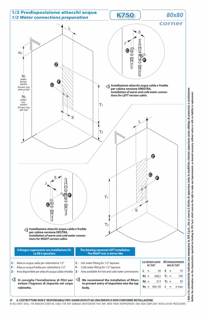
1/2 Predisposizione attacchi acqua1/2 Water connections preparation
Le misure sono in “cm”
C - Attacco acqua calda per rubinetteria 1/2” F - Attacco acqua fredda per rubinetteria 1/2” Z - Area disponibile per attacchi acqua calda e fredda
Si consiglia l’installazione di filtri per evitare l’ingresso di impurità nel corpo rubinetto.
All measurement are in “cm”
C - Hot water fitting for 1/2” tapwareF - Cold water fitting for 1/2” tapwareZ - Area available for hot and cold water connections
We recommend the installation of filters to prevent entry of impurities into the tap body.
Il disegno rappresenta una installazione SX. La DX è speculare.
The drawing represent LEFT installation. The RIGHT inst. is mirror-like
K750
T2
T1
S
L
T2
T1
S
L
FC
CF
Z
N1piatto senza piedini
N2piatto con
piedini
Shower traywithout feet
Shower traywith feet
Z
N3
J
S
F
C
JS
F
C
Installazione attacchi acqua calda e fredda per cabina versione SINISTRA.Installation of warm and cold water connec-tions for LEFT version cabin.
L = 20
N1 = 208,5
N2 = 213
N3 = Min 50
S = 10
T1 = 100
T2 = 30
J = 3 max
corner80x80
Installazione attacchi acqua calda e fredda per cabina versione DESTRA.Installation of warm and cold water connec-tions for RIGHT version cabin.
I dat
i e le
car
atte
rist
iche
indi
cate
non
impe
gnan
o la
SFA
S.p
.A.,
che
si r
iser
va il
dir
itto
di a
ppor
tare
tut
te le
mod
ifich
e ri
tenu
te o
ppor
tune
sen
za o
bblig
o di
pre
avvi
so o
sos
titu
zion
e
!!! IL COSTRUTTORE NON E’ RESPONSABILE PER I DANNI DOVUTI AD UNA ERRATA O NON CONFORME INSTALLAZIONE.
Le misure sono in “cm”
IN NO EVENT SHALL THE MANUFACTURER BE LIABLE FOR ANY DAMAGES WHATSOEVER THAT MAY ARISE FROM INAPPROPRIATE AND NON-COMPLIANT INSTALLATION PROCEDURES.
Neith
er th
e in
form
atio
n no
r the
char
acte
ristic
s rep
orte
d ar
e bi
ndin
g fo
r SFA
S.p
.A. w
hich
rese
rves
the
right
to m
ake
any
impr
ovem
ents
, as d
eem
ed n
eces
sary
, with
out n
otice
or w
ith n
o lia
bilit
y to
repl
acem
ent.
All measurement are in “cm”
Accertarsi che l’impianto elettrico dello stabile sia conforme alle norme CEI 64.8 e protetto da un interruttore differenziale accertandosi che l’impianto di messa a terra sia efficiente e conforme alle disposizioni CEI. Il collegamento elettrico dell’impianto idromassaggio, va eseguito in modo fisso e permanente e deve essere controllato da un interruttore omnipolare con apertura dei contatti di almeno 3 mm, ed avere un potere di interruzione pari a 16A o 25A (a seconda del tipo di sistema), posto fuori dalle zone 0,1,2,3 e comunque lontano da possibili erogazioni o spruzzi d’acqua.Il cavo di alimentazione alla centralina, deve essere del tipo H05 a tre conduttori di sezione non inferiore a 2,5mm2 o 4,0mm2 (a seconda del tipo di sistema). Per il passaggio nelle pareti di detto cavo, usare l’apposito tubo corrugato di tipo PT. La responsabilità del Costruttore decade nel caso in cui i componenti elettrici dell’apparecchio, vengano manomessi o sostituiti con ricambi non originali e/o non riconosciuti conformi dal Costruttore.
Make sure the building electrical installation conforms to the EIC 64.8 standard and that it is protected by a magnetic circuit breaker, ascertaining also that the grounding terminal is efficient and fully compliant with IEC provisions. The electrical connection of the bathtub shall be carried out permanently and be monitored by a single-pole switch, whose contacts can open 3mm at least and featuring a cut-out capacity equal to 16A or 25A (based on the system type), located outside areas 0,1, 2 and 3 and at any rate, as far as possible from water supply or jets. The power-cord to the controller must be H05 with a three conductor cross-section is not less than 2,5 mm2 or 4,0mm2 (based on the system type). To drive the cord through the walls, use the appropriately supplied PT corrugated pipe.This warranty is avoid if failure has resulted from the electrical components of the appliance being either tampered with or replaced by second-hand spare parts,and/or spare parts whose conformity is not acknowledged by the manufacturer.
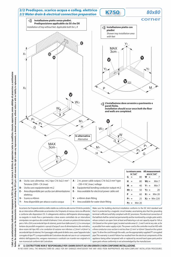
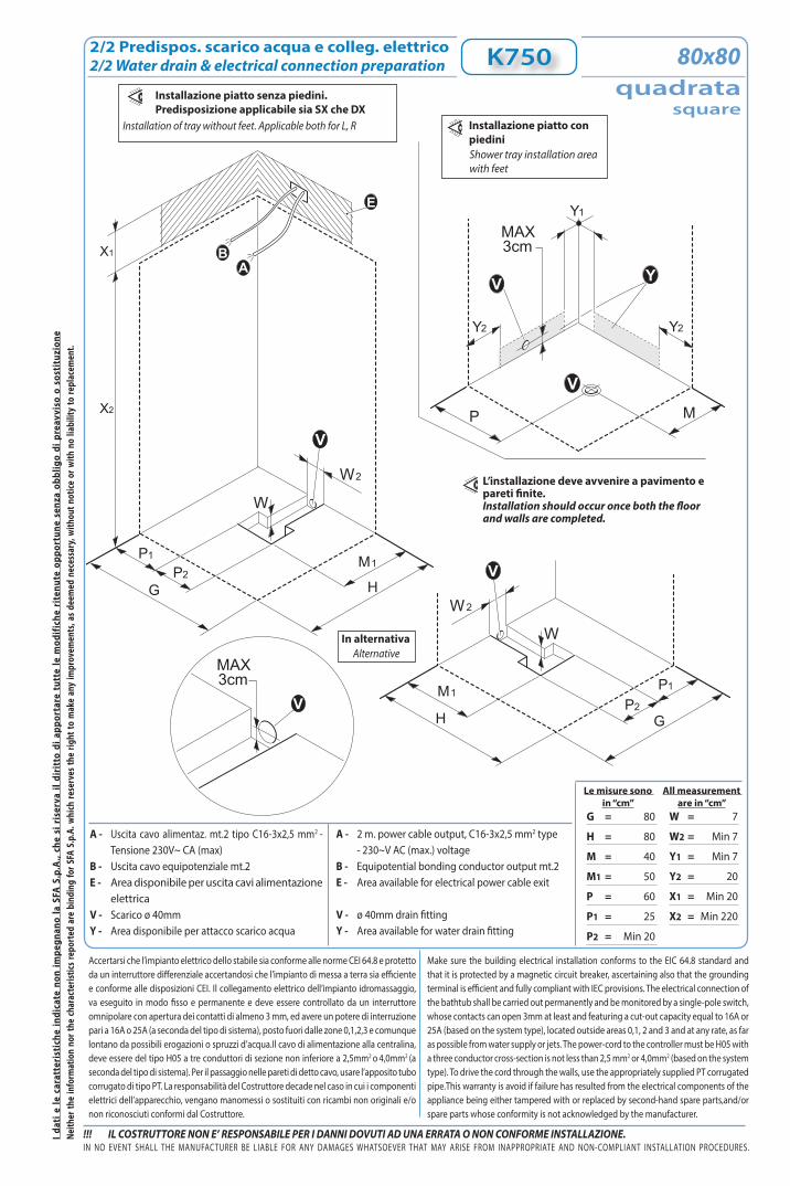
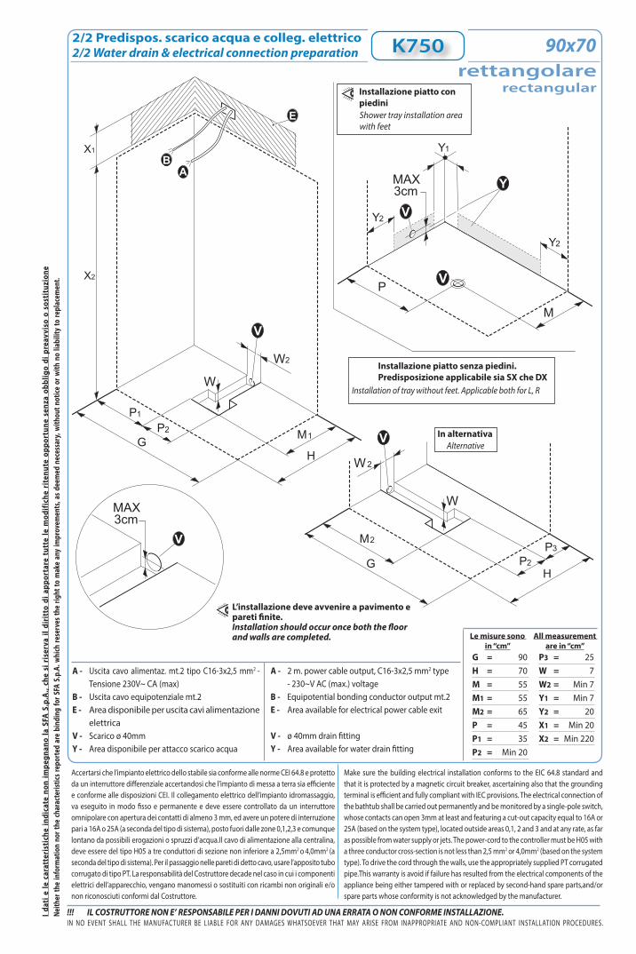
2/2 Predispos. scarico acqua e colleg. elettrico2/2 Water drain & electrical connection preparation K750
A - Uscita cavo alimentaz. mt.2 tipo C16-3x2,5 mm2 - Tensione 230V~ CA (max)
B - Uscita cavo equipotenziale mt.2E - Area disponibile per uscita cavi alimentazione
elettricaV - Scarico ø 40mm Y - Area disponibile per attacco scarico acqua
A - 2 m. power cable output, C16-3x2,5 mm2 type - 230~V AC (max.) voltageB - Equipotential bonding conductor output mt.2E - Area available for electrical power cable exit
V - ø 40mm drain fittingY - Area available for water drain fitting
Installazione piatto con piediniShower tray installation area with feet
G = 80
H = 80
M = 40
M1 = 50
P = 60
P1 = 25
P2 = Min 20
W = 7
W2 = Min 7
Y1 = Min 7
Y2 = 20
X1 = Min 20
X2 = Min 220
In alternativaAlternative
Installazione piatto senza piedini. Predisposizione applicabile sia SX che DX
Installation of tray without feet. Applicable both for L, R
G
P
V
H
P M
V
1
P2M1
W
W2
3cmMAX
G
P
V
H
1
P2M1
W
W2
V Y
Y1
Y2Y2
ABX1
X2
E
3cmMAX
V
L’installazione deve avvenire a pavimento e pareti finite.Installation should occur once both the floor and walls are completed.
corner80x80
Dati tecnici
(1) Prevedere due tubi flessibili(2) Per pressioni superiori a 5 bar installare un riduttore di pressione a
monte della tubatura.(3) Per garantire il corretto funzionamento la temperatura dell’acqua
deve essere di 50°C
(1) To foresse two flexible pipes.(2) If the water pressure exceeds 5 bars, a pressure reducer should be
fitted upstream from the feed pipe.(3) To ensure proper operation, minimum water temperature shouldbe
Picture represents left installation.“REVERSIBLE MULTIFUNCTION SHOWER”
Scheda tecnica di “Pre-Installazione”“Pre-Installation” technical sheet
Nr.
Dimensioni “cm”tolleranza ±5mm
Dimensions “cm”tolerance ±5mm
Ed. 01- 02/2021
VAPOR
K750
Nr.
corner
2-K750Ed. 01- 02/2021
4,5 cm - senza piedini
12 cm - con piedini
208,5senza piediniwithout feet
213con piedini
90
90
______
min. 50
without feet
with feet
with feet
erogatore vaporesteam dispenser
generatore di vaporesteam generator
230~
50
3000
12
1/2”
40
2
2
1÷5
8÷13
2
85
5÷25
50÷80
90x90corner
K750corner
I dat
i e le
car
atte
rist
iche
indi
cate
non
impe
gnan
o la
SFA
S.p
.A.,
che
si r
iser
va il
dir
itto
di a
ppor
tare
tut
te le
mod
ifich
e ri
tenu
te o
ppor
tune
sen
za o
bblig
o di
pre
avvi
so o
sos
titu
zion
e
!!! IL COSTRUTTORE NON E’ RESPONSABILE PER I DANNI DOVUTI AD UNA ERRATA O NON CONFORME INSTALLAZIONE.IN NO EVENT SHALL THE MANUFACTURER BE LIABLE FOR ANY DAMAGES WHATSOEVER THAT MAY ARISE FROM INAPPROPRIATE AND NON-COMPLIANT INSTALLATION PROCEDURES.
Neith
er th
e in
form
atio
n no
r the
char
acte
ristic
s rep
orte
d ar
e bi
ndin
g fo
r SFA
S.p
.A. w
hich
rese
rves
the
right
to m
ake
any
impr
ovem
ents
, as d
eem
ed n
eces
sary
, with
out n
otice
or w
ith n
o lia
bilit
y to
repl
acem
ent.
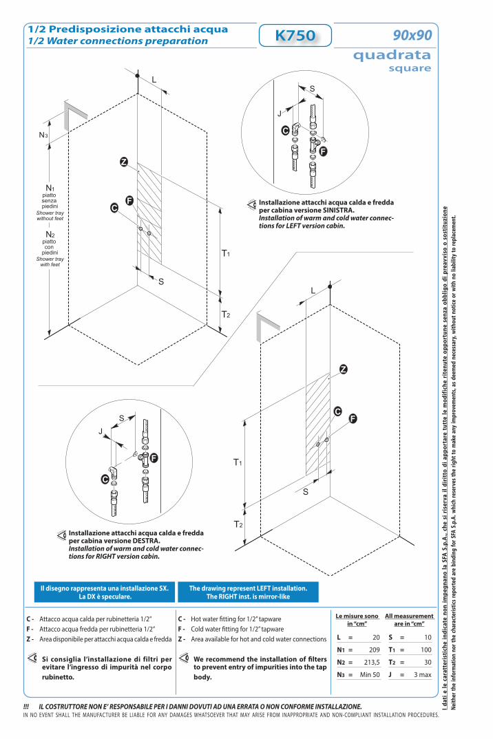
1/2 Predisposizione attacchi acqua1/2 Water connections preparation
Le misure sono in “cm”
C - Attacco acqua calda per rubinetteria 1/2” F - Attacco acqua fredda per rubinetteria 1/2” Z - Area disponibile per attacchi acqua calda e fredda
Si consiglia l’installazione di filtri per evitare l’ingresso di impurità nel corpo rubinetto.
All measurement are in “cm”
C - Hot water fitting for 1/2” tapwareF - Cold water fitting for 1/2” tapwareZ - Area available for hot and cold water connections
We recommend the installation of filters to prevent entry of impurities into the tap body.
Il disegno rappresenta una installazione SX. La DX è speculare.
The drawing represent LEFT installation. The RIGHT inst. is mirror-like
K750corner
90x90
T2
T1
S
L
T2
T1
S
L
FC
CF
Z
N1piatto senza piedini
N2piatto con
piedini
Shower traywithout feet
Shower traywith feet
Z
N3
J
S
F
C
JS
F
C
Installazione attacchi acqua calda e fredda per cabina versione SINISTRA.Installation of warm and cold water connec-tions for LEFT version cabin.
Installazione attacchi acqua calda e fredda per cabina versione DESTRA.Installation of warm and cold water connec-tions for RIGHT version cabin.
L = 20
N1 = 208,5
N2 = 213
N3 = Min 50
S = 10
T1 = 100
T2 = 30
J = 3 max
I dat
i e le
car
atte
rist
iche
indi
cate
non
impe
gnan
o la
SFA
S.p
.A.,
che
si r
iser
va il
dir
itto
di a
ppor
tare
tut
te le
mod
ifich
e ri
tenu
te o
ppor
tune
sen
za o
bblig
o di
pre
avvi
so o
sos
titu
zion
e
!!! IL COSTRUTTORE NON E’ RESPONSABILE PER I DANNI DOVUTI AD UNA ERRATA O NON CONFORME INSTALLAZIONE.
Le misure sono in “cm”
IN NO EVENT SHALL THE MANUFACTURER BE LIABLE FOR ANY DAMAGES WHATSOEVER THAT MAY ARISE FROM INAPPROPRIATE AND NON-COMPLIANT INSTALLATION PROCEDURES.
Neith
er th
e in
form
atio
n no
r the
char
acte
ristic
s rep
orte
d ar
e bi
ndin
g fo
r SFA
S.p
.A. w
hich
rese
rves
the
right
to m
ake
any
impr
ovem
ents
, as d
eem
ed n
eces
sary
, with
out n
otice
or w
ith n
o lia
bilit
y to
repl
acem
ent.
All measurement are in “cm”
Accertarsi che l’impianto elettrico dello stabile sia conforme alle norme CEI 64.8 e protetto da un interruttore differenziale accertandosi che l’impianto di messa a terra sia efficiente e conforme alle disposizioni CEI. Il collegamento elettrico dell’impianto idromassaggio, va eseguito in modo fisso e permanente e deve essere controllato da un interruttore omnipolare con apertura dei contatti di almeno 3 mm, ed avere un potere di interruzione pari a 16A o 25A (a seconda del tipo di sistema), posto fuori dalle zone 0,1,2,3 e comunque lontano da possibili erogazioni o spruzzi d’acqua.Il cavo di alimentazione alla centralina, deve essere del tipo H05 a tre conduttori di sezione non inferiore a 2,5mm2 o 4,0mm2 (a seconda del tipo di sistema). Per il passaggio nelle pareti di detto cavo, usare l’apposito tubo corrugato di tipo PT. La responsabilità del Costruttore decade nel caso in cui i componenti elettrici dell’apparecchio, vengano manomessi o sostituiti con ricambi non originali e/o non riconosciuti conformi dal Costruttore.
Make sure the building electrical installation conforms to the EIC 64.8 standard and that it is protected by a magnetic circuit breaker, ascertaining also that the grounding terminal is efficient and fully compliant with IEC provisions. The electrical connection of the bathtub shall be carried out permanently and be monitored by a single-pole switch, whose contacts can open 3mm at least and featuring a cut-out capacity equal to 16A or 25A (based on the system type), located outside areas 0,1, 2 and 3 and at any rate, as far as possible from water supply or jets. The power-cord to the controller must be H05 with a three conductor cross-section is not less than 2,5 mm2 or 4,0mm2 (based on the system type). To drive the cord through the walls, use the appropriately supplied PT corrugated pipe.This warranty is avoid if failure has resulted from the electrical components of the appliance being either tampered with or replaced by second-hand spare parts,and/or spare parts whose conformity is not acknowledged by the manufacturer.
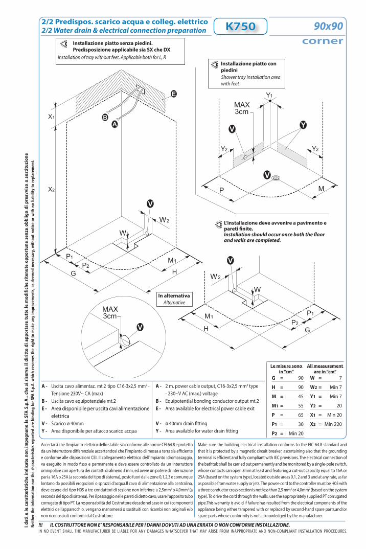
2/2 Predispos. scarico acqua e colleg. elettrico2/2 Water drain & electrical connection preparation K750
G = 90
H = 90
M = 45
M1 = 55
P = 65
P1 = 30
P2 = Min 20
W = 7
W2 = Min 7
Y1 = Min 7
Y2 = 20
X1 = Min 20
X2 = Min 220
corner90x90
A - Uscita cavo alimentaz. mt.2 tipo C16-3x2,5 mm2 - Tensione 230V~ CA (max)
B - Uscita cavo equipotenziale mt.2E - Area disponibile per uscita cavi alimentazione
elettricaV - Scarico ø 40mm Y - Area disponibile per attacco scarico acqua
A - 2 m. power cable output, C16-3x2,5 mm2 type - 230~V AC (max.) voltageB - Equipotential bonding conductor output mt.2E - Area available for electrical power cable exit
V - ø 40mm drain fittingY - Area available for water drain fitting
Installazione piatto con piediniShower tray installation area with feet
In alternativaAlternative
Installazione piatto senza piedini. Predisposizione applicabile sia SX che DX
Installation of tray without feet. Applicable both for L, R
G
P
V
H
P M
V
1
P2M1
W
W2
3cmMAX
G
P
V
H
1
P2M1
W
W2
V Y
Y1
Y2Y2
ABX1
X2
E
3cmMAX
V
L’installazione deve avvenire a pavimento e pareti finite.Installation should occur once both the floor and walls are completed.
Dati tecnici
(1) Prevedere due tubi flessibili(2) Per pressioni superiori a 5 bar installare un riduttore di pressione a
monte della tubatura.(3) Per garantire il corretto funzionamento la temperatura dell’acqua
deve essere di 50°C
(1) To foresse two flexible pipes.(2) If the water pressure exceeds 5 bars, a pressure reducer should be
fitted upstream from the feed pipe.(3) To ensure proper operation, minimum water temperature shouldbe
Picture represents left installation.“REVERSIBLE MULTIFUNCTION SHOWER”
Scheda tecnica di “Pre-Installazione”“Pre-Installation” technical sheet
Nr.
Dimensioni “cm”tolleranza ±5mm
Dimensions “cm”tolerance ±5mm
Ed. 01- 02/2021
VAPOR
K750
Nr. 3-K750Ed. 01- 02/2021
80
___
80
min. 50
4,5 cm - senza piedini
12 cm - con piedini
208,5senza piediniwithout feet
213con piedini
without feet
with feet
with feet
erogatore vaporesteam dispenser
generatore di vaporesteam generator
230~
50
3000
12
1/2”
40
2
2
1÷5
8÷13
2
80
5÷25
50÷80
80x80
K750quadrata
square
quadratasquare
I dat
i e le
car
atte
rist
iche
indi
cate
non
impe
gnan
o la
SFA
S.p
.A.,
che
si r
iser
va il
dir
itto
di a
ppor
tare
tut
te le
mod
ifich
e ri
tenu
te o
ppor
tune
sen
za o
bblig
o di
pre
avvi
so o
sos
titu
zion
e
!!! IL COSTRUTTORE NON E’ RESPONSABILE PER I DANNI DOVUTI AD UNA ERRATA O NON CONFORME INSTALLAZIONE.IN NO EVENT SHALL THE MANUFACTURER BE LIABLE FOR ANY DAMAGES WHATSOEVER THAT MAY ARISE FROM INAPPROPRIATE AND NON-COMPLIANT INSTALLATION PROCEDURES.
Neith
er th
e in
form
atio
n no
r the
char
acte
ristic
s rep
orte
d ar
e bi
ndin
g fo
r SFA
S.p
.A. w
hich
rese
rves
the
right
to m
ake
any
impr
ovem
ents
, as d
eem
ed n
eces
sary
, with
out n
otice
or w
ith n
o lia
bilit
y to
repl
acem
ent.
1/2 Predisposizione attacchi acqua1/2 Water connections preparation
Le misure sono in “cm”
C - Attacco acqua calda per rubinetteria 1/2” F - Attacco acqua fredda per rubinetteria 1/2” Z - Area disponibile per attacchi acqua calda e fredda
Si consiglia l’installazione di filtri per evitare l’ingresso di impurità nel corpo rubinetto.
All measurement are in “cm”
C - Hot water fitting for 1/2” tapwareF - Cold water fitting for 1/2” tapwareZ - Area available for hot and cold water connections
We recommend the installation of filters to prevent entry of impurities into the tap body.
Il disegno rappresenta una installazione SX. La DX è speculare.
The drawing represent LEFT installation. The RIGHT inst. is mirror-like
K750
T2
T1
S
L
T2
T1
S
L
FC
CF
Z
N1piatto senza piedini
N2piatto con
piedini
Shower traywithout feet
Shower traywith feet
Z
N3
J
S
F
C
JS
F
C
L = 20
N1 = 209
N2 = 213,5
N3 = Min 50
S = 10
T1 = 100
T2 = 30
J = 3 max
Installazione attacchi acqua calda e fredda per cabina versione SINISTRA.Installation of warm and cold water connec-tions for LEFT version cabin.
Installazione attacchi acqua calda e fredda per cabina versione DESTRA.Installation of warm and cold water connec-tions for RIGHT version cabin.
quadratasquare
80x80
I dat
i e le
car
atte
rist
iche
indi
cate
non
impe
gnan
o la
SFA
S.p
.A.,
che
si r
iser
va il
dir
itto
di a
ppor
tare
tut
te le
mod
ifich
e ri
tenu
te o
ppor
tune
sen
za o
bblig
o di
pre
avvi
so o
sos
titu
zion
e
!!! IL COSTRUTTORE NON E’ RESPONSABILE PER I DANNI DOVUTI AD UNA ERRATA O NON CONFORME INSTALLAZIONE.
Le misure sono in “cm”
IN NO EVENT SHALL THE MANUFACTURER BE LIABLE FOR ANY DAMAGES WHATSOEVER THAT MAY ARISE FROM INAPPROPRIATE AND NON-COMPLIANT INSTALLATION PROCEDURES.
Neith
er th
e in
form
atio
n no
r the
char
acte
ristic
s rep
orte
d ar
e bi
ndin
g fo
r SFA
S.p
.A. w
hich
rese
rves
the
right
to m
ake
any
impr
ovem
ents
, as d
eem
ed n
eces
sary
, with
out n
otice
or w
ith n
o lia
bilit
y to
repl
acem
ent.
All measurement are in “cm”
Accertarsi che l’impianto elettrico dello stabile sia conforme alle norme CEI 64.8 e protetto da un interruttore differenziale accertandosi che l’impianto di messa a terra sia efficiente e conforme alle disposizioni CEI. Il collegamento elettrico dell’impianto idromassaggio, va eseguito in modo fisso e permanente e deve essere controllato da un interruttore omnipolare con apertura dei contatti di almeno 3 mm, ed avere un potere di interruzione pari a 16A o 25A (a seconda del tipo di sistema), posto fuori dalle zone 0,1,2,3 e comunque lontano da possibili erogazioni o spruzzi d’acqua.Il cavo di alimentazione alla centralina, deve essere del tipo H05 a tre conduttori di sezione non inferiore a 2,5mm2 o 4,0mm2 (a seconda del tipo di sistema). Per il passaggio nelle pareti di detto cavo, usare l’apposito tubo corrugato di tipo PT. La responsabilità del Costruttore decade nel caso in cui i componenti elettrici dell’apparecchio, vengano manomessi o sostituiti con ricambi non originali e/o non riconosciuti conformi dal Costruttore.
Make sure the building electrical installation conforms to the EIC 64.8 standard and that it is protected by a magnetic circuit breaker, ascertaining also that the grounding terminal is efficient and fully compliant with IEC provisions. The electrical connection of the bathtub shall be carried out permanently and be monitored by a single-pole switch, whose contacts can open 3mm at least and featuring a cut-out capacity equal to 16A or 25A (based on the system type), located outside areas 0,1, 2 and 3 and at any rate, as far as possible from water supply or jets. The power-cord to the controller must be H05 with a three conductor cross-section is not less than 2,5 mm2 or 4,0mm2 (based on the system type). To drive the cord through the walls, use the appropriately supplied PT corrugated pipe.This warranty is avoid if failure has resulted from the electrical components of the appliance being either tampered with or replaced by second-hand spare parts,and/or spare parts whose conformity is not acknowledged by the manufacturer.
2/2 Predispos. scarico acqua e colleg. elettrico2/2 Water drain & electrical connection preparation K750
G = 80
H = 80
M = 40
M1 = 50
P = 60
P1 = 25
P2 = Min 20
W = 7
W2 = Min 7
Y1 = Min 7
Y2 = 20
X1 = Min 20
X2 = Min 220
quadratasquare
80x80
A - Uscita cavo alimentaz. mt.2 tipo C16-3x2,5 mm2 - Tensione 230V~ CA (max)
B - Uscita cavo equipotenziale mt.2E - Area disponibile per uscita cavi alimentazione
elettricaV - Scarico ø 40mm Y - Area disponibile per attacco scarico acqua
A - 2 m. power cable output, C16-3x2,5 mm2 type - 230~V AC (max.) voltageB - Equipotential bonding conductor output mt.2E - Area available for electrical power cable exit
V - ø 40mm drain fittingY - Area available for water drain fitting
Installazione piatto con piediniShower tray installation area with feet
In alternativaAlternative
Installazione piatto senza piedini. Predisposizione applicabile sia SX che DX
Installation of tray without feet. Applicable both for L, R
G
P
V
H
P M
V
1
P2M1
W
W2
3cmMAX
G
P
V
H
1
P2M1
W
W2
V Y
Y1
Y2Y2
ABX1
X2
E
3cmMAX
V
L’installazione deve avvenire a pavimento e pareti finite.Installation should occur once both the floor and walls are completed.
Dati tecnici
(1) Prevedere due tubi flessibili(2) Per pressioni superiori a 5 bar installare un riduttore di pressione a
monte della tubatura.(3) Per garantire il corretto funzionamento la temperatura dell’acqua
deve essere di 50°C
(1) To foresse two flexible pipes.(2) If the water pressure exceeds 5 bars, a pressure reducer should be
fitted upstream from the feed pipe.(3) To ensure proper operation, minimum water temperature shouldbe
Picture represents left installation.“REVERSIBLE MULTIFUNCTION SHOWER”
Scheda tecnica di “Pre-Installazione”“Pre-Installation” technical sheet
Nr.
Dimensioni “cm”tolleranza ±5mm
Dimensions “cm”tolerance ±5mm
Ed. 01- 02/2021
VAPOR
K750
Nr. 4-K750Ed. 01- 02/2021
90
___
90
min. 50
4,5 cm - senza piedini
12 cm - con piedini
208,5senza piediniwithout feet
213con piedini
without feet
with feet
with feet
erogatore vaporesteam dispenser
generatore di vaporesteam generator
230~
50
3000
12
1/2”
40
2
2
1÷5
8÷13
2
85
5÷25
50÷80
90x90
K750quadrata
square
quadratasquare
I dat
i e le
car
atte
rist
iche
indi
cate
non
impe
gnan
o la
SFA
S.p
.A.,
che
si r
iser
va il
dir
itto
di a
ppor
tare
tut
te le
mod
ifich
e ri
tenu
te o
ppor
tune
sen
za o
bblig
o di
pre
avvi
so o
sos
titu
zion
e
!!! IL COSTRUTTORE NON E’ RESPONSABILE PER I DANNI DOVUTI AD UNA ERRATA O NON CONFORME INSTALLAZIONE.IN NO EVENT SHALL THE MANUFACTURER BE LIABLE FOR ANY DAMAGES WHATSOEVER THAT MAY ARISE FROM INAPPROPRIATE AND NON-COMPLIANT INSTALLATION PROCEDURES.
Neith
er th
e in
form
atio
n no
r the
char
acte
ristic
s rep
orte
d ar
e bi
ndin
g fo
r SFA
S.p
.A. w
hich
rese
rves
the
right
to m
ake
any
impr
ovem
ents
, as d
eem
ed n
eces
sary
, with
out n
otice
or w
ith n
o lia
bilit
y to
repl
acem
ent.
1/2 Predisposizione attacchi acqua1/2 Water connections preparation
Le misure sono in “cm”
C - Attacco acqua calda per rubinetteria 1/2” F - Attacco acqua fredda per rubinetteria 1/2” Z - Area disponibile per attacchi acqua calda e fredda
Si consiglia l’installazione di filtri per evitare l’ingresso di impurità nel corpo rubinetto.
All measurement are in “cm”
C - Hot water fitting for 1/2” tapwareF - Cold water fitting for 1/2” tapwareZ - Area available for hot and cold water connections
We recommend the installation of filters to prevent entry of impurities into the tap body.
Il disegno rappresenta una installazione SX. La DX è speculare.
The drawing represent LEFT installation. The RIGHT inst. is mirror-like
K750
T2
T1
S
L
T2
T1
S
L
FC
CF
Z
N1piatto senza piedini
N2piatto con
piedini
Shower traywithout feet
Shower traywith feet
Z
N3
J
S
F
C
JS
F
C
Installazione attacchi acqua calda e fredda per cabina versione SINISTRA.Installation of warm and cold water connec-tions for LEFT version cabin.
Installazione attacchi acqua calda e fredda per cabina versione DESTRA.Installation of warm and cold water connec-tions for RIGHT version cabin.
L = 20
N1 = 209
N2 = 213,5
N3 = Min 50
S = 10
T1 = 100
T2 = 30
J = 3 max
quadratasquare
90x90
I dat
i e le
car
atte
rist
iche
indi
cate
non
impe
gnan
o la
SFA
S.p
.A.,
che
si r
iser
va il
dir
itto
di a
ppor
tare
tut
te le
mod
ifich
e ri
tenu
te o
ppor
tune
sen
za o
bblig
o di
pre
avvi
so o
sos
titu
zion
e
!!! IL COSTRUTTORE NON E’ RESPONSABILE PER I DANNI DOVUTI AD UNA ERRATA O NON CONFORME INSTALLAZIONE.
Le misure sono in “cm”
IN NO EVENT SHALL THE MANUFACTURER BE LIABLE FOR ANY DAMAGES WHATSOEVER THAT MAY ARISE FROM INAPPROPRIATE AND NON-COMPLIANT INSTALLATION PROCEDURES.
Neith
er th
e in
form
atio
n no
r the
char
acte
ristic
s rep
orte
d ar
e bi
ndin
g fo
r SFA
S.p
.A. w
hich
rese
rves
the
right
to m
ake
any
impr
ovem
ents
, as d
eem
ed n
eces
sary
, with
out n
otice
or w
ith n
o lia
bilit
y to
repl
acem
ent.
All measurement are in “cm”
Accertarsi che l’impianto elettrico dello stabile sia conforme alle norme CEI 64.8 e protetto da un interruttore differenziale accertandosi che l’impianto di messa a terra sia efficiente e conforme alle disposizioni CEI. Il collegamento elettrico dell’impianto idromassaggio, va eseguito in modo fisso e permanente e deve essere controllato da un interruttore omnipolare con apertura dei contatti di almeno 3 mm, ed avere un potere di interruzione pari a 16A o 25A (a seconda del tipo di sistema), posto fuori dalle zone 0,1,2,3 e comunque lontano da possibili erogazioni o spruzzi d’acqua.Il cavo di alimentazione alla centralina, deve essere del tipo H05 a tre conduttori di sezione non inferiore a 2,5mm2 o 4,0mm2 (a seconda del tipo di sistema). Per il passaggio nelle pareti di detto cavo, usare l’apposito tubo corrugato di tipo PT. La responsabilità del Costruttore decade nel caso in cui i componenti elettrici dell’apparecchio, vengano manomessi o sostituiti con ricambi non originali e/o non riconosciuti conformi dal Costruttore.
Make sure the building electrical installation conforms to the EIC 64.8 standard and that it is protected by a magnetic circuit breaker, ascertaining also that the grounding terminal is efficient and fully compliant with IEC provisions. The electrical connection of the bathtub shall be carried out permanently and be monitored by a single-pole switch, whose contacts can open 3mm at least and featuring a cut-out capacity equal to 16A or 25A (based on the system type), located outside areas 0,1, 2 and 3 and at any rate, as far as possible from water supply or jets. The power-cord to the controller must be H05 with a three conductor cross-section is not less than 2,5 mm2 or 4,0mm2 (based on the system type). To drive the cord through the walls, use the appropriately supplied PT corrugated pipe.This warranty is avoid if failure has resulted from the electrical components of the appliance being either tampered with or replaced by second-hand spare parts,and/or spare parts whose conformity is not acknowledged by the manufacturer.
2/2 Predispos. scarico acqua e colleg. elettrico2/2 Water drain & electrical connection preparation K750
G = 90
H = 90
M = 45
M1 = 55
P = 65
P1 = 30
P2 = Min 20
W = 7
W2 = Min 7
Y1 = Min 7
Y2 = 20
X1 = Min 20
X2 = Min 220
quadratasquare
90x90
A - Uscita cavo alimentaz. mt.2 tipo C16-3x2,5 mm2 - Tensione 230V~ CA (max)
B - Uscita cavo equipotenziale mt.2E - Area disponibile per uscita cavi alimentazione
elettricaV - Scarico ø 40mm Y - Area disponibile per attacco scarico acqua
A - 2 m. power cable output, C16-3x2,5 mm2 type - 230~V AC (max.) voltageB - Equipotential bonding conductor output mt.2E - Area available for electrical power cable exit
V - ø 40mm drain fittingY - Area available for water drain fitting
Installazione piatto con piediniShower tray installation area with feet
In alternativaAlternative
Installazione piatto senza piedini. Predisposizione applicabile sia SX che DX
Installation of tray without feet. Applicable both for L, R
G
P
V
H
P M
V
1
P2M1
W
W2
3cmMAX
G
P
V
H
1
P2M1
W
W2
V Y
Y1
Y2Y2
ABX1
X2
E
3cmMAX
V
L’installazione deve avvenire a pavimento e pareti finite.Installation should occur once both the floor and walls are completed.
Dati tecnici
(1) Prevedere due tubi flessibili(2) Per pressioni superiori a 5 bar installare un riduttore di pressione a
monte della tubatura.(3) Per garantire il corretto funzionamento la temperatura dell’acqua
deve essere di 50°C
(1) To foresse two flexible pipes.(2) If the water pressure exceeds 5 bars, a pressure reducer should be
fitted upstream from the feed pipe.(3) To ensure proper operation, minimum water temperature shouldbe
Picture represents left installation.“REVERSIBLE MULTIFUNCTION SHOWER”
Scheda tecnica di “Pre-Installazione”“Pre-Installation” technical sheet
Nr.
Dimensioni “cm”tolleranza ±5mm
Dimensions “cm”tolerance ±5mm
Ed. 01- 02/2021
VAPOR
K750
5-K750
90x70
90
70
___
min. 50
208,5senza piediniwithout feet
213con piediniwith feet
4,5 cm - senza piedini
12 cm- con piedini
without feet
with feet
erogatore vaporesteam dispenser
generatore di vaporesteam generator
rettangolarerectangular
230~
50
3000
12
1/2”
40
2
2
1÷5
8÷13
2
85
5÷25
50÷80
K750rettangolare
rectangular
I dat
i e le
car
atte
rist
iche
indi
cate
non
impe
gnan
o la
SFA
S.p
.A.,
che
si r
iser
va il
dir
itto
di a
ppor
tare
tut
te le
mod
ifich
e ri
tenu
te o
ppor
tune
sen
za o
bblig
o di
pre
avvi
so o
sos
titu
zion
e
!!! IL COSTRUTTORE NON E’ RESPONSABILE PER I DANNI DOVUTI AD UNA ERRATA O NON CONFORME INSTALLAZIONE.IN NO EVENT SHALL THE MANUFACTURER BE LIABLE FOR ANY DAMAGES WHATSOEVER THAT MAY ARISE FROM INAPPROPRIATE AND NON-COMPLIANT INSTALLATION PROCEDURES.
Neith
er th
e in
form
atio
n no
r the
char
acte
ristic
s rep
orte
d ar
e bi
ndin
g fo
r SFA
S.p
.A. w
hich
rese
rves
the
right
to m
ake
any
impr
ovem
ents
, as d
eem
ed n
eces
sary
, with
out n
otice
or w
ith n
o lia
bilit
y to
repl
acem
ent.
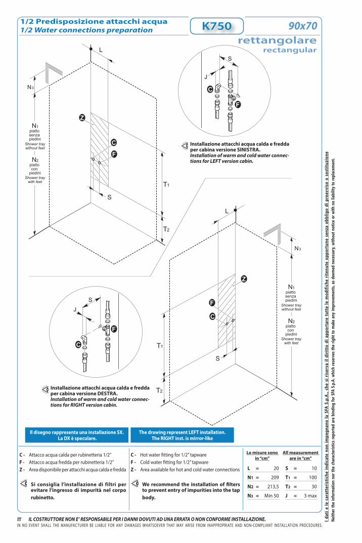
1/2 Predisposizione attacchi acqua1/2 Water connections preparation
Le misure sono in “cm”
C - Attacco acqua calda per rubinetteria 1/2” F - Attacco acqua fredda per rubinetteria 1/2” Z - Area disponibile per attacchi acqua calda e fredda
Si consiglia l’installazione di filtri per evitare l’ingresso di impurità nel corpo rubinetto.
All measurement are in “cm”
C - Hot water fitting for 1/2” tapwareF - Cold water fitting for 1/2” tapwareZ - Area available for hot and cold water connections
We recommend the installation of filters to prevent entry of impurities into the tap body.
Il disegno rappresenta una installazione SX. La DX è speculare.
The drawing represent LEFT installation. The RIGHT inst. is mirror-like
K750
N1piatto senza piedini
N2piatto con
piedini
Shower traywithout feet
Shower traywith feet
N3
T2
T1
S
L
F
C
Z
N1piatto senza piedini
N2piatto con
piedini
Shower traywithout feet
Shower traywith feet
N3
T2
T1
S
L
F
C
Z
J
S
F
C
JS
F
C
Installazione attacchi acqua calda e fredda per cabina versione SINISTRA.Installation of warm and cold water connec-tions for LEFT version cabin.
Installazione attacchi acqua calda e fredda per cabina versione DESTRA.Installation of warm and cold water connec-tions for RIGHT version cabin.
L = 20
N1 = 209
N2 = 213,5
N3 = Min 50
S = 10
T1 = 100
T2 = 30
J = 3 max
rettangolarerectangular
90x70
I dat
i e le
car
atte
rist
iche
indi
cate
non
impe
gnan
o la
SFA
S.p
.A.,
che
si r
iser
va il
dir
itto
di a
ppor
tare
tut
te le
mod
ifich
e ri
tenu
te o
ppor
tune
sen
za o
bblig
o di
pre
avvi
so o
sos
titu
zion
e
!!! IL COSTRUTTORE NON E’ RESPONSABILE PER I DANNI DOVUTI AD UNA ERRATA O NON CONFORME INSTALLAZIONE.
Le misure sono in “cm”
IN NO EVENT SHALL THE MANUFACTURER BE LIABLE FOR ANY DAMAGES WHATSOEVER THAT MAY ARISE FROM INAPPROPRIATE AND NON-COMPLIANT INSTALLATION PROCEDURES.
Neith
er th
e in
form
atio
n no
r the
char
acte
ristic
s rep
orte
d ar
e bi
ndin
g fo
r SFA
S.p
.A. w
hich
rese
rves
the
right
to m
ake
any
impr
ovem
ents
, as d
eem
ed n
eces
sary
, with
out n
otice
or w
ith n
o lia
bilit
y to
repl
acem
ent.
All measurement are in “cm”
Accertarsi che l’impianto elettrico dello stabile sia conforme alle norme CEI 64.8 e protetto da un interruttore differenziale accertandosi che l’impianto di messa a terra sia efficiente e conforme alle disposizioni CEI. Il collegamento elettrico dell’impianto idromassaggio, va eseguito in modo fisso e permanente e deve essere controllato da un interruttore omnipolare con apertura dei contatti di almeno 3 mm, ed avere un potere di interruzione pari a 16A o 25A (a seconda del tipo di sistema), posto fuori dalle zone 0,1,2,3 e comunque lontano da possibili erogazioni o spruzzi d’acqua.Il cavo di alimentazione alla centralina, deve essere del tipo H05 a tre conduttori di sezione non inferiore a 2,5mm2 o 4,0mm2 (a seconda del tipo di sistema). Per il passaggio nelle pareti di detto cavo, usare l’apposito tubo corrugato di tipo PT. La responsabilità del Costruttore decade nel caso in cui i componenti elettrici dell’apparecchio, vengano manomessi o sostituiti con ricambi non originali e/o non riconosciuti conformi dal Costruttore.
Make sure the building electrical installation conforms to the EIC 64.8 standard and that it is protected by a magnetic circuit breaker, ascertaining also that the grounding terminal is efficient and fully compliant with IEC provisions. The electrical connection of the bathtub shall be carried out permanently and be monitored by a single-pole switch, whose contacts can open 3mm at least and featuring a cut-out capacity equal to 16A or 25A (based on the system type), located outside areas 0,1, 2 and 3 and at any rate, as far as possible from water supply or jets. The power-cord to the controller must be H05 with a three conductor cross-section is not less than 2,5 mm2 or 4,0mm2 (based on the system type). To drive the cord through the walls, use the appropriately supplied PT corrugated pipe.This warranty is avoid if failure has resulted from the electrical components of the appliance being either tampered with or replaced by second-hand spare parts,and/or spare parts whose conformity is not acknowledged by the manufacturer.
2/2 Predispos. scarico acqua e colleg. elettrico2/2 Water drain & electrical connection preparation K750
G = 90H = 70M = 55M1 = 55M2 = 65P = 45P1 = 35P2 = Min 20
P3 = 25W = 7W2 = Min 7Y1 = Min 7Y2 = 20X1 = Min 20X2 = Min 220
rettangolarerectangular
90x70
A - Uscita cavo alimentaz. mt.2 tipo C16-3x2,5 mm2 - Tensione 230V~ CA (max)
B - Uscita cavo equipotenziale mt.2E - Area disponibile per uscita cavi alimentazione
elettricaV - Scarico ø 40mm Y - Area disponibile per attacco scarico acqua
A - 2 m. power cable output, C16-3x2,5 mm2 type - 230~V AC (max.) voltageB - Equipotential bonding conductor output mt.2E - Area available for electrical power cable exit
V - ø 40mm drain fittingY - Area available for water drain fitting
In alternativaAlternative
Installazione piatto senza piedini. Predisposizione applicabile sia SX che DX
P
M
3cmMAX
V
Y
Y2
Y2
V
Y1
H
PG
3
P2
M2
V
W
W2
G
P
V
H
1
P2 M1
W
W2
AB
X1
X2
E
3cmMAX
V
L’installazione deve avvenire a pavimento e pareti finite.Installation should occur once both the floor and walls are completed.
Installation of tray without feet. Applicable both for L, R
Installazione piatto con piediniShower tray installation area with feet
Dati tecnici
(1) Prevedere due tubi flessibili(2) Per pressioni superiori a 5 bar installare un riduttore di pressione a
monte della tubatura.(3) Per garantire il corretto funzionamento la temperatura dell’acqua
deve essere di 50°C
(1) To foresse two flexible pipes.(2) If the water pressure exceeds 5 bars, a pressure reducer should be
fitted upstream from the feed pipe.(3) To ensure proper operation, minimum water temperature shouldbe
Picture represents left installation.“REVERSIBLE MULTIFUNCTION SHOWER”
Scheda tecnica di “Pre-Installazione”“Pre-Installation” technical sheet
Nr.
Dimensioni “cm”tolleranza ±5mm
Dimensions “cm”tolerance ±5mm
Ed. 01- 02/2021
VAPOR
K750
110
70
___
208,5senza piediniwithout feet
213con piediniwith feet
4,5 cm - senza piedini
12 cm- con piedini
without feet
with feet
min. 50
erogatore vaporesteam dispenser
generatore di vaporesteam generator
6-K750
110x70rettangolarerectangular
230~
50
3000
12
1/2”
40
2
2
1÷5
8÷13
2
95
5÷25
50÷80
K750rettangolare
rectangular
I dat
i e le
car
atte
rist
iche
indi
cate
non
impe
gnan
o la
SFA
S.p
.A.,
che
si r
iser
va il
dir
itto
di a
ppor
tare
tut
te le
mod
ifich
e ri
tenu
te o
ppor
tune
sen
za o
bblig
o di
pre
avvi
so o
sos
titu
zion
e
!!! IL COSTRUTTORE NON E’ RESPONSABILE PER I DANNI DOVUTI AD UNA ERRATA O NON CONFORME INSTALLAZIONE.IN NO EVENT SHALL THE MANUFACTURER BE LIABLE FOR ANY DAMAGES WHATSOEVER THAT MAY ARISE FROM INAPPROPRIATE AND NON-COMPLIANT INSTALLATION PROCEDURES.
Neith
er th
e in
form
atio
n no
r the
char
acte
ristic
s rep
orte
d ar
e bi
ndin
g fo
r SFA
S.p
.A. w
hich
rese
rves
the
right
to m
ake
any
impr
ovem
ents
, as d
eem
ed n
eces
sary
, with
out n
otice
or w
ith n
o lia
bilit
y to
repl
acem
ent.
1/2 Predisposizione attacchi acqua1/2 Water connections preparation
Le misure sono in “cm”
C - Attacco acqua calda per rubinetteria 1/2” F - Attacco acqua fredda per rubinetteria 1/2” Z - Area disponibile per attacchi acqua calda e fredda
Si consiglia l’installazione di filtri per evitare l’ingresso di impurità nel corpo rubinetto.
All measurement are in “cm”
C - Hot water fitting for 1/2” tapwareF - Cold water fitting for 1/2” tapwareZ - Area available for hot and cold water connections
We recommend the installation of filters to prevent entry of impurities into the tap body.
Il disegno rappresenta una installazione SX. La DX è speculare.
The drawing represent LEFT installation. The RIGHT inst. is mirror-like
K750
N1piatto senza piedini
N2piatto con
piedini
Shower traywithout feet
Shower traywith feet
N3
T2
T1
S
L
F
C
Z
N1piatto senza piedini
N2piatto con
piedini
Shower traywithout feet
Shower traywith feet
N3
T2
T1
S
L
F
C
Z
J
S
F
C
JS
F
C
Installazione attacchi acqua calda e fredda per cabina versione SINISTRA.Installation of warm and cold water connec-tions for LEFT version cabin.
Installazione attacchi acqua calda e fredda per cabina versione DESTRA.Installation of warm and cold water connec-tions for RIGHT version cabin.
L = 20
N1 = 209
N2 = 213,5
N3 = Min 50
S = 10
T1 = 100
T2 = 30
J = 3 max
rettangolarerectangular
110x70
I dat
i e le
car
atte
rist
iche
indi
cate
non
impe
gnan
o la
SFA
S.p
.A.,
che
si r
iser
va il
dir
itto
di a
ppor
tare
tut
te le
mod
ifich
e ri
tenu
te o
ppor
tune
sen
za o
bblig
o di
pre
avvi
so o
sos
titu
zion
e
!!! IL COSTRUTTORE NON E’ RESPONSABILE PER I DANNI DOVUTI AD UNA ERRATA O NON CONFORME INSTALLAZIONE.
Le misure sono in “cm”
IN NO EVENT SHALL THE MANUFACTURER BE LIABLE FOR ANY DAMAGES WHATSOEVER THAT MAY ARISE FROM INAPPROPRIATE AND NON-COMPLIANT INSTALLATION PROCEDURES.
Neith
er th
e in
form
atio
n no
r the
char
acte
ristic
s rep
orte
d ar
e bi
ndin
g fo
r SFA
S.p
.A. w
hich
rese
rves
the
right
to m
ake
any
impr
ovem
ents
, as d
eem
ed n
eces
sary
, with
out n
otice
or w
ith n
o lia
bilit
y to
repl
acem
ent.
All measurement are in “cm”
Accertarsi che l’impianto elettrico dello stabile sia conforme alle norme CEI 64.8 e protetto da un interruttore differenziale accertandosi che l’impianto di messa a terra sia efficiente e conforme alle disposizioni CEI. Il collegamento elettrico dell’impianto idromassaggio, va eseguito in modo fisso e permanente e deve essere controllato da un interruttore omnipolare con apertura dei contatti di almeno 3 mm, ed avere un potere di interruzione pari a 16A o 25A (a seconda del tipo di sistema), posto fuori dalle zone 0,1,2,3 e comunque lontano da possibili erogazioni o spruzzi d’acqua.Il cavo di alimentazione alla centralina, deve essere del tipo H05 a tre conduttori di sezione non inferiore a 2,5mm2 o 4,0mm2 (a seconda del tipo di sistema). Per il passaggio nelle pareti di detto cavo, usare l’apposito tubo corrugato di tipo PT. La responsabilità del Costruttore decade nel caso in cui i componenti elettrici dell’apparecchio, vengano manomessi o sostituiti con ricambi non originali e/o non riconosciuti conformi dal Costruttore.
Make sure the building electrical installation conforms to the EIC 64.8 standard and that it is protected by a magnetic circuit breaker, ascertaining also that the grounding terminal is efficient and fully compliant with IEC provisions. The electrical connection of the bathtub shall be carried out permanently and be monitored by a single-pole switch, whose contacts can open 3mm at least and featuring a cut-out capacity equal to 16A or 25A (based on the system type), located outside areas 0,1, 2 and 3 and at any rate, as far as possible from water supply or jets. The power-cord to the controller must be H05 with a three conductor cross-section is not less than 2,5 mm2 or 4,0mm2 (based on the system type). To drive the cord through the walls, use the appropriately supplied PT corrugated pipe.This warranty is avoid if failure has resulted from the electrical components of the appliance being either tampered with or replaced by second-hand spare parts,and/or spare parts whose conformity is not acknowledged by the manufacturer.
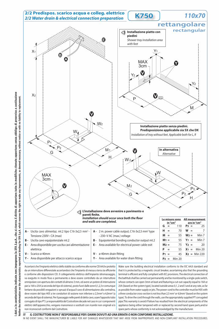
2/2 Predispos. scarico acqua e colleg. elettrico2/2 Water drain & electrical connection preparation K750
rettangolarerectangular
110x70
A - Uscita cavo alimentaz. mt.2 tipo C16-3x2,5 mm2 - Tensione 230V~ CA (max)
B - Uscita cavo equipotenziale mt.2E - Area disponibile per uscita cavi alimentazione
elettricaV - Scarico ø 40mm Y - Area disponibile per attacco scarico acqua
A - 2 m. power cable output, C16-3x2,5 mm2 type - 230~V AC (max.) voltageB - Equipotential bonding conductor output mt.2E - Area available for electrical power cable exit
V - ø 40mm drain fittingY - Area available for water drain fitting
In alternativaAlternative
Installazione piatto senza piedini. Predisposizione applicabile sia SX che DX
P
M
3cmMAX
V
Y
Y2
Y2
V
Y1
H
PG
3
P2
M2
V
W
W2
G
P
V
H
1
P2 M1
W
W2
AB
X1
X2
E
3cmMAX
V
L’installazione deve avvenire a pavimento e pareti finite.Installation should occur once both the floor and walls are completed.
Installation of tray without feet. Applicable both for L, R
Installazione piatto con piediniShower tray installation area with feet
G = 110H = 70M = 55M1 = 55M2 = 75P = 55P1 = 45P2 = Min 20
P3 = 25W = 7W2 = Min 7Y1 = Min 7Y2 = 20X1 = Min 20X2 = Min 220
Dati tecnici
(1) Prevedere due tubi flessibili(2) Per pressioni superiori a 5 bar installare un riduttore di pressione a
monte della tubatura.(3) Per garantire il corretto funzionamento la temperatura dell’acqua
deve essere di 50°C
(1) To foresse two flexible pipes.(2) If the water pressure exceeds 5 bars, a pressure reducer should be
fitted upstream from the feed pipe.(3) To ensure proper operation, minimum water temperature shouldbe
Picture represents left installation.“REVERSIBLE MULTIFUNCTION SHOWER”
Scheda tecnica di “Pre-Installazione”“Pre-Installation” technical sheet
Nr.
Dimensioni “cm”tolleranza ±5mm
Dimensions “cm”tolerance ±5mm
Ed. 01- 02/2021
VAPOR
K750
230~
50
3000
12
1/2”
40
2
2
1÷5
8÷13
2
95
5÷25
50÷80
K750rettangolare
rectangular
7-K750
rettangolarerectangular 100x80
100
80
___
208,5senza piediniwithout feet
213con piediniwith feet
4,5 cm - senza piedini
12 cm- con piedini
without feet
with feet
min. 50
erogatore vaporesteam dispenser
generatore di vaporesteam generator
I dat
i e le
car
atte
rist
iche
indi
cate
non
impe
gnan
o la
SFA
S.p
.A.,
che
si r
iser
va il
dir
itto
di a
ppor
tare
tut
te le
mod
ifich
e ri
tenu
te o
ppor
tune
sen
za o
bblig
o di
pre
avvi
so o
sos
titu
zion
e
!!! IL COSTRUTTORE NON E’ RESPONSABILE PER I DANNI DOVUTI AD UNA ERRATA O NON CONFORME INSTALLAZIONE.IN NO EVENT SHALL THE MANUFACTURER BE LIABLE FOR ANY DAMAGES WHATSOEVER THAT MAY ARISE FROM INAPPROPRIATE AND NON-COMPLIANT INSTALLATION PROCEDURES.
Neith
er th
e in
form
atio
n no
r the
char
acte
ristic
s rep
orte
d ar
e bi
ndin
g fo
r SFA
S.p
.A. w
hich
rese
rves
the
right
to m
ake
any
impr
ovem
ents
, as d
eem
ed n
eces
sary
, with
out n
otice
or w
ith n
o lia
bilit
y to
repl
acem
ent.
1/2 Predisposizione attacchi acqua1/2 Water connections preparation
Le misure sono in “cm”
C - Attacco acqua calda per rubinetteria 1/2” F - Attacco acqua fredda per rubinetteria 1/2” Z - Area disponibile per attacchi acqua calda e fredda
Si consiglia l’installazione di filtri per evitare l’ingresso di impurità nel corpo rubinetto.
All measurement are in “cm”
C - Hot water fitting for 1/2” tapwareF - Cold water fitting for 1/2” tapwareZ - Area available for hot and cold water connections
We recommend the installation of filters to prevent entry of impurities into the tap body.
Il disegno rappresenta una installazione SX. La DX è speculare.
The drawing represent LEFT installation. The RIGHT inst. is mirror-like
K750
N1piatto senza piedini
N2piatto con
piedini
Shower traywithout feet
Shower traywith feet
N3
T2
T1
S
L
F
C
Z
N1piatto senza piedini
N2piatto con
piedini
Shower traywithout feet
Shower traywith feet
N3
T2
T1
S
L
F
C
Z
J
S
F
C
JS
F
C
Installazione attacchi acqua calda e fredda per cabina versione SINISTRA.Installation of warm and cold water connec-tions for LEFT version cabin.
Installazione attacchi acqua calda e fredda per cabina versione DESTRA.Installation of warm and cold water connec-tions for RIGHT version cabin.
L = 20
N1 = 209
N2 = 213,5
N3 = Min 50
S = 10
T1 = 100
T2 = 30
J = 3 max
rettangolarerectangular
100x80
I dat
i e le
car
atte
rist
iche
indi
cate
non
impe
gnan
o la
SFA
S.p
.A.,
che
si r
iser
va il
dir
itto
di a
ppor
tare
tut
te le
mod
ifich
e ri
tenu
te o
ppor
tune
sen
za o
bblig
o di
pre
avvi
so o
sos
titu
zion
e
!!! IL COSTRUTTORE NON E’ RESPONSABILE PER I DANNI DOVUTI AD UNA ERRATA O NON CONFORME INSTALLAZIONE.
Le misure sono in “cm”
IN NO EVENT SHALL THE MANUFACTURER BE LIABLE FOR ANY DAMAGES WHATSOEVER THAT MAY ARISE FROM INAPPROPRIATE AND NON-COMPLIANT INSTALLATION PROCEDURES.
Neith
er th
e in
form
atio
n no
r the
char
acte
ristic
s rep
orte
d ar
e bi
ndin
g fo
r SFA
S.p
.A. w
hich
rese
rves
the
right
to m
ake
any
impr
ovem
ents
, as d
eem
ed n
eces
sary
, with
out n
otice
or w
ith n
o lia
bilit
y to
repl
acem
ent.
All measurement are in “cm”
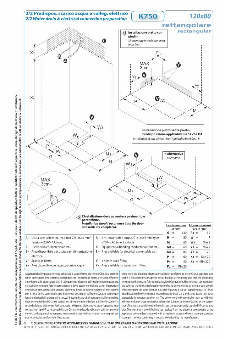
Accertarsi che l’impianto elettrico dello stabile sia conforme alle norme CEI 64.8 e protetto da un interruttore differenziale accertandosi che l’impianto di messa a terra sia efficiente e conforme alle disposizioni CEI. Il collegamento elettrico dell’impianto idromassaggio, va eseguito in modo fisso e permanente e deve essere controllato da un interruttore omnipolare con apertura dei contatti di almeno 3 mm, ed avere un potere di interruzione pari a 16A o 25A (a seconda del tipo di sistema), posto fuori dalle zone 0,1,2,3 e comunque lontano da possibili erogazioni o spruzzi d’acqua.Il cavo di alimentazione alla centralina, deve essere del tipo H05 a tre conduttori di sezione non inferiore a 2,5mm2 o 4,0mm2 (a seconda del tipo di sistema). Per il passaggio nelle pareti di detto cavo, usare l’apposito tubo corrugato di tipo PT. La responsabilità del Costruttore decade nel caso in cui i componenti elettrici dell’apparecchio, vengano manomessi o sostituiti con ricambi non originali e/o non riconosciuti conformi dal Costruttore.
Make sure the building electrical installation conforms to the EIC 64.8 standard and that it is protected by a magnetic circuit breaker, ascertaining also that the grounding terminal is efficient and fully compliant with IEC provisions. The electrical connection of the bathtub shall be carried out permanently and be monitored by a single-pole switch, whose contacts can open 3mm at least and featuring a cut-out capacity equal to 16A or 25A (based on the system type), located outside areas 0,1, 2 and 3 and at any rate, as far as possible from water supply or jets. The power-cord to the controller must be H05 with a three conductor cross-section is not less than 2,5 mm2 or 4,0mm2 (based on the system type). To drive the cord through the walls, use the appropriately supplied PT corrugated pipe.This warranty is avoid if failure has resulted from the electrical components of the appliance being either tampered with or replaced by second-hand spare parts,and/or spare parts whose conformity is not acknowledged by the manufacturer.
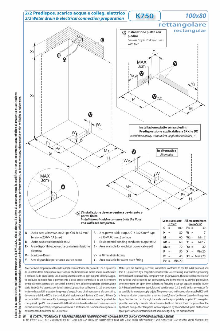
2/2 Predispos. scarico acqua e colleg. elettrico2/2 Water drain & electrical connection preparation K750
A - Uscita cavo alimentaz. mt.2 tipo C16-3x2,5 mm2 - Tensione 230V~ CA (max)
B - Uscita cavo equipotenziale mt.2E - Area disponibile per uscita cavi alimentazione
elettricaV - Scarico ø 40mm Y - Area disponibile per attacco scarico acqua
A - 2 m. power cable output, C16-3x2,5 mm2 type - 230~V AC (max.) voltageB - Equipotential bonding conductor output mt.2E - Area available for electrical power cable exit
V - ø 40mm drain fittingY - Area available for water drain fitting
In alternativaAlternative
Installazione piatto senza piedini. Predisposizione applicabile sia SX che DX
P
M
3cmMAX
V
Y
Y2
Y2
V
Y1
H
PG
3
P2
M2
V
W
W2
G
P
V
H
1
P2 M1
W
W2
AB
X1
X2
E
3cmMAX
V
L’installazione deve avvenire a pavimento e pareti finite.Installation should occur once both the floor and walls are completed.
Installation of tray without feet. Applicable both for L, R
G = 100H = 80M = 60M1 = 60M2 = 70P = 50P1 = 40P2 = Min 20
P3 = 30W = 7W2 = Min 7Y1 = Min 7Y2 = 20X1 = Min 20X2 = Min 220
rettangolarerectangular
100x80
Installazione piatto con piediniShower tray installation area with feet
Dati tecnici
(1) Prevedere due tubi flessibili(2) Per pressioni superiori a 5 bar installare un riduttore di pressione a
monte della tubatura.(3) Per garantire il corretto funzionamento la temperatura dell’acqua
deve essere di 50°C
(1) To foresse two flexible pipes.(2) If the water pressure exceeds 5 bars, a pressure reducer should be
fitted upstream from the feed pipe.(3) To ensure proper operation, minimum water temperature shouldbe
Picture represents left installation.“REVERSIBLE MULTIFUNCTION SHOWER”
Scheda tecnica di “Pre-Installazione”“Pre-Installation” technical sheet
Nr.
Dimensioni “cm”tolleranza ±5mm
Dimensions “cm”tolerance ±5mm
Ed. 01- 02/2021
VAPOR
K750
120
80
___
208,5senza piediniwithout feet
213con piediniwith feet
4,5 cm - senza piedini
12 cm- con piedini
without feet
with feet
min. 50
erogatore vaporesteam dispenser
generatore di vaporesteam generator
230~
50
3000
12
1/2”
40
2
2
1÷5
8÷13
2
105
5÷25
50÷80
K750rettangolare
rectangular
8-K750
rettangolarerectangular 120x80
I dat
i e le
car
atte
rist
iche
indi
cate
non
impe
gnan
o la
SFA
S.p
.A.,
che
si r
iser
va il
dir
itto
di a
ppor
tare
tut
te le
mod
ifich
e ri
tenu
te o
ppor
tune
sen
za o
bblig
o di
pre
avvi
so o
sos
titu
zion
e
!!! IL COSTRUTTORE NON E’ RESPONSABILE PER I DANNI DOVUTI AD UNA ERRATA O NON CONFORME INSTALLAZIONE.IN NO EVENT SHALL THE MANUFACTURER BE LIABLE FOR ANY DAMAGES WHATSOEVER THAT MAY ARISE FROM INAPPROPRIATE AND NON-COMPLIANT INSTALLATION PROCEDURES.
Neith
er th
e in
form
atio
n no
r the
char
acte
ristic
s rep
orte
d ar
e bi
ndin
g fo
r SFA
S.p
.A. w
hich
rese
rves
the
right
to m
ake
any
impr
ovem
ents
, as d
eem
ed n
eces
sary
, with
out n
otice
or w
ith n
o lia
bilit
y to
repl
acem
ent.
1/2 Predisposizione attacchi acqua1/2 Water connections preparation
Le misure sono in “cm”
C - Attacco acqua calda per rubinetteria 1/2” F - Attacco acqua fredda per rubinetteria 1/2” Z - Area disponibile per attacchi acqua calda e fredda
Si consiglia l’installazione di filtri per evitare l’ingresso di impurità nel corpo rubinetto.
All measurement are in “cm”
C - Hot water fitting for 1/2” tapwareF - Cold water fitting for 1/2” tapwareZ - Area available for hot and cold water connections
We recommend the installation of filters to prevent entry of impurities into the tap body.
Il disegno rappresenta una installazione SX. La DX è speculare.
The drawing represent LEFT installation. The RIGHT inst. is mirror-like
K750
N1piatto senza piedini
N2piatto con
piedini
Shower traywithout feet
Shower traywith feet
N3
T2
T1
S
L
F
C
Z
N1piatto senza piedini
N2piatto con
piedini
Shower traywithout feet
Shower traywith feet
N3
T2
T1
S
L
F
C
Z
J
S
F
C
JS
F
C
Installazione attacchi acqua calda e fredda per cabina versione SINISTRA.Installation of warm and cold water connec-tions for LEFT version cabin.
Installazione attacchi acqua calda e fredda per cabina versione DESTRA.Installation of warm and cold water connec-tions for RIGHT version cabin.
L = 20
N1 = 209
N2 = 213,5
N3 = Min 50
S = 10
T1 = 100
T2 = 30
J = 3 max
rettangolarerectangular
120x80
I dat
i e le
car
atte
rist
iche
indi
cate
non
impe
gnan
o la
SFA
S.p
.A.,
che
si r
iser
va il
dir
itto
di a
ppor
tare
tut
te le
mod
ifich
e ri
tenu
te o
ppor
tune
sen
za o
bblig
o di
pre
avvi
so o
sos
titu
zion
e
!!! IL COSTRUTTORE NON E’ RESPONSABILE PER I DANNI DOVUTI AD UNA ERRATA O NON CONFORME INSTALLAZIONE.
Le misure sono in “cm”
IN NO EVENT SHALL THE MANUFACTURER BE LIABLE FOR ANY DAMAGES WHATSOEVER THAT MAY ARISE FROM INAPPROPRIATE AND NON-COMPLIANT INSTALLATION PROCEDURES.
Neith
er th
e in
form
atio
n no
r the
char
acte
ristic
s rep
orte
d ar
e bi
ndin
g fo
r SFA
S.p
.A. w
hich
rese
rves
the
right
to m
ake
any
impr
ovem
ents
, as d
eem
ed n
eces
sary
, with
out n
otice
or w
ith n
o lia
bilit
y to
repl
acem
ent.
All measurement are in “cm”
Accertarsi che l’impianto elettrico dello stabile sia conforme alle norme CEI 64.8 e protetto da un interruttore differenziale accertandosi che l’impianto di messa a terra sia efficiente e conforme alle disposizioni CEI. Il collegamento elettrico dell’impianto idromassaggio, va eseguito in modo fisso e permanente e deve essere controllato da un interruttore omnipolare con apertura dei contatti di almeno 3 mm, ed avere un potere di interruzione pari a 16A o 25A (a seconda del tipo di sistema), posto fuori dalle zone 0,1,2,3 e comunque lontano da possibili erogazioni o spruzzi d’acqua.Il cavo di alimentazione alla centralina, deve essere del tipo H05 a tre conduttori di sezione non inferiore a 2,5mm2 o 4,0mm2 (a seconda del tipo di sistema). Per il passaggio nelle pareti di detto cavo, usare l’apposito tubo corrugato di tipo PT. La responsabilità del Costruttore decade nel caso in cui i componenti elettrici dell’apparecchio, vengano manomessi o sostituiti con ricambi non originali e/o non riconosciuti conformi dal Costruttore.
Make sure the building electrical installation conforms to the EIC 64.8 standard and that it is protected by a magnetic circuit breaker, ascertaining also that the grounding terminal is efficient and fully compliant with IEC provisions. The electrical connection of the bathtub shall be carried out permanently and be monitored by a single-pole switch, whose contacts can open 3mm at least and featuring a cut-out capacity equal to 16A or 25A (based on the system type), located outside areas 0,1, 2 and 3 and at any rate, as far as possible from water supply or jets. The power-cord to the controller must be H05 with a three conductor cross-section is not less than 2,5 mm2 or 4,0mm2 (based on the system type). To drive the cord through the walls, use the appropriately supplied PT corrugated pipe.This warranty is avoid if failure has resulted from the electrical components of the appliance being either tampered with or replaced by second-hand spare parts,and/or spare parts whose conformity is not acknowledged by the manufacturer.
2/2 Predispos. scarico acqua e colleg. elettrico2/2 Water drain & electrical connection preparation K750
A - Uscita cavo alimentaz. mt.2 tipo C16-3x2,5 mm2 - Tensione 230V~ CA (max)
B - Uscita cavo equipotenziale mt.2E - Area disponibile per uscita cavi alimentazione
elettricaV - Scarico ø 40mm Y - Area disponibile per attacco scarico acqua
A - 2 m. power cable output, C16-3x2,5 mm2 type - 230~V AC (max.) voltageB - Equipotential bonding conductor output mt.2E - Area available for electrical power cable exit
V - ø 40mm drain fittingY - Area available for water drain fitting
In alternativaAlternative
Installazione piatto senza piedini. Predisposizione applicabile sia SX che DX
P
M
3cmMAX
V
Y
Y2
Y2
V
Y1
H
PG
3
P2
M2
V
W
W2
G
P
V
H
1
P2 M1
W
W2
AB
X1
X2
E
3cmMAX
V
L’installazione deve avvenire a pavimento e pareti finite.Installation should occur once both the floor and walls are completed.
Installation of tray without feet. Applicable both for L, R
G = 120H = 80M = 60M1 = 60M2 = 80P = 60P1 = 50P2 = Min 20
P3 = 30W = 7W2 = Min 7Y1 = Min 7Y2 = 20X1 = Min 20X2 = Min 220
Installazione piatto con piediniShower tray installation area with feet