Page 1
MINI UPS SYSTEM
CHAPTER 1: INTRODUCTION
1.1 Introduction:
1.1.1 Uninterrupted Power Supply Systems (UPS)
Power failures, load shedding and low voltage have become our constant
compassion. Over the years, the situation has worsened instead of improving. The business
and work schedules get affected, students lose precious study time, and the family’s
entertainment time disappears, not to mention the inconvenience caused during the winter.
The problem is compounded with the popularity of PCs in the modern house holds.
Commercial power supply is not capable of providing clean and consistent
electric power demanded by sensitive equipment. Sensitive equipment requires a consistent
supply of power of the correct specifications for their operation, hardware protection,
continuity of process, storage and transfer of information, and safety of personal Computer
network communication links, electronic medical equipment, industrial process control,
remote installations like offshore operations, online applications such as airline reservations
etc., are examples of such critical loads. Beyond any dispute, the installation of an
Uninterrupted Power Supply (UPS) system is now a day accepted as being a vital element
in the protection of sensitive equipment.
1.2 BATTERY-LIFE OF THE UPS SYSTEM
The most critical part of the UPS system is the battery. The battery often
represents half the original cost of UPS system. It is the weakest link in the UPS system.
An incorrect selection of the battery type may reduce the initial cost but would adversely
affect the overall life of the system.
The battery life is determined by the UPS service conditions. For online
UPS systems, the battery remains on floating charge for longer time. Float performance
characteristics has a strong influence on battery life. Prolonged breakdowns can cause the
battery to deep discharge several times in a week if not in a day. This in turn affects battery
life drastically, as a thumb rule; a deep discharge below 80% battery capacity reduces the VBCE (ECE)
1
Page 2
MINI UPS SYSTEM
life of the battery by 25%. The mini UPS system can be used to run the electric load (bulb)
when the mains supply is OFF.
1.3 Project Overview
The project “Mini UPS System” can be done using comparator IC, relay, AC fan
transformer we can generate voltage with inverter for controlling the load.
1.4 Thesis
The thesis explains the implementation of “Mini UPS System”. The organization of the
thesis is explained here with:
Chapter 1 Presents introduction to the overall thesis and the overview of the project. In
the project overview a brief introduction of Mini UPS System and its applications are
discussed.
Chapter 2 Presents the topic embedded systems. It explains the about what is embedded
systems, need for embedded systems, explanation of it along with its applications.
Chapter 3 Presents the hardware description. It deals with the block diagram of the
project and explains the purpose of each block. In the same chapter the explanation of
MOSFET, Mono stable multi vibrator, comparator IC, battery power supply, transformer is
considered.
Chapter 4 presents the project description along with Mono stable multi vibrator,
MOSFET, comparator IC module interfacing to transformer.
Chapter 6 Presents the advantages, disadvantages and applications of the project.
Chapter 7 Presents the results, conclusion and future scope of the project.
VBCE (ECE) 2
Page 3
MINI UPS SYSTEM
CHAPTER 2: EMBEDDED SYSTEMS
2.1 Embedded Systems
An embedded system is a computer system designed to perform one or a
few dedicated functions often with real-time computing constraints. It is embedded as part
of a complete device often including hardware and mechanical parts. By contrast, a
general-purpose computer, such as a personal computer (PC), is designed to be flexible and
to meet a wide range of end-user needs. Embedded systems control many devices in
common use today.
Embedded systems are controlled by one or more main processing cores that
are typically either microcontrollers or digital signal processors (DSP). The key
characteristic, however, is being dedicated to handle a particular task, which may require
very powerful processors.
In general, "embedded system" is not a strictly definable term, as most systems
have some element of extensibility or programmability. Moreover, even systems which
don't expose programmability as a primary feature generally need to support software
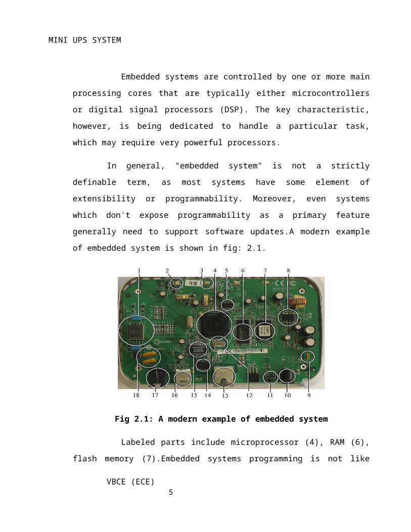
updates.A modern example of embedded system is shown in fig: 2.1.
VBCE (ECE) 3
Page 4
MINI UPS SYSTEM
Fig 2.1: A modern example of embedded system
Labeled parts include microprocessor (4), RAM (6), flash memory
(7).Embedded systems programming is not like normal PC programming. In many ways,
programming for an embedded system is like programming PC 15 years ago. The hardware
for the system is usually chosen to make the device as cheap as possible. Spending an extra
dollar a unit in order to make things easier to program can cost millions. Hiring a
programmer for an extra month is cheap in comparison. This means the programmer must
make do with slow processors and low memory, while at the same time battling a need for
efficiency not seen in most PC applications. Below is a list of issues specific to the
embedded field.
2.1.1 History
In the earliest years of computers in the 1930–40s, computers were
sometimes dedicated to a single task, but were far too large and expensive for most kinds of
tasks performed by embedded computers of today. Over time however, the concept
of programmable controllers evolved from traditional electromechanical sequencers, via
solid state devices, to the use of computer technology.
One of the first recognizably modern embedded systems was the Apollo
Guidance Computer, developed by Charles Stark Draper at the MIT Instrumentation
Laboratory. At the project's inception, the Apollo guidance computer was considered the
riskiest item in the Apollo project as it employed the then newly developed monolithic
integrated circuits to reduce the size and weight. An early mass-produced embedded system
was the Autonetics D-17 guidance computer for the Minuteman missile, released in 1961. It
was built from transistor logic and had a hard disk for main memory. When the Minuteman
II went into production in 1966, the D-17 was replaced with a new computer that was the
first high-volume use of integrated circuits.
2.1.2 Tools
Embedded development makes up a small fraction of total programming.
There's also a large number of embedded architectures, unlike the PC world where 1
VBCE (ECE) 4
Page 5
MINI UPS SYSTEM
instruction set rules, and the Unix world where there's only 3 or 4 major ones. This means
that the tools are more expensive. It also means that they're lowering featured, and less
developed. On a major embedded project, at some point you will almost always find a
compiler bug of some sort.
Debugging tools are another issue. Since you can't always run general
programs on your embedded processor, you can't always run a debugger on it. This makes
fixing your program difficult. Special hardware such as JTAG ports can overcome this
issue in part. However, if you stop on a breakpoint when your system is controlling real
world hardware (such as a motor), permanent equipment damage can occur. As a result,
people doing embedded programming quickly become masters at using serial IO channels
and error message style debugging.
2.1.3 Resources
To save costs, embedded systems frequently have the cheapest processors
that can do the job. This means your programs need to be written as efficiently as possible.
When dealing with large data sets, issues like memory cache misses that never matter in PC
programming can hurt you. Luckily, this won't happen too often- use reasonably efficient
algorithms to start, and optimize only when necessary. Of course, normal profilers won't
work well, due to the same reason debuggers don't work well.
2.1.4 Real Time Issues
Embedded systems frequently control hardware, and must be able to respond
to them in real time. Failure to do so could cause inaccuracy in measurements, or even
damage hardware such as motors. This is made even more difficult by the lack of resources
available. Almost all embedded systems need to be able to prioritize some tasks over
others, and to be able to put off/skip low priority tasks such as UI in favor of high priority
tasks like hardware control.
2.2 Need for Embedded Systems
The uses of embedded systems are virtually limitless, because every day
new products are introduced to the market that utilizes embedded computers in novel ways. VBCE (ECE)
5
Page 6
MINI UPS SYSTEM
In recent years, hardware such as microprocessors, microcontrollers, and FPGA chips have
become much cheaper. So when implementing a new form of control, it's wiser to just buy
the generic chip and write your own custom software for it. Producing a custom-made chip
to handle a particular task or set of tasks costs far more time and money. Many embedded
computers even come with extensive libraries, so that "writing your own software"
becomes a very trivial task indeed. From an implementation viewpoint, there is a major
difference between a computer and an embedded system. Embedded systems are often
required to provide Real-Time response. The main elements that make embedded systems
unique are its reliability and ease in debugging.
2.2.1 Debugging
Embedded debugging may be performed at different levels, depending on
the facilities available. From simplest to most sophisticate they can be roughly grouped into
the following areas:
Interactive resident debugging, using the simple shell provided by the embedded operating
system (e.g. Forth and Basic)
External debugging using logging or serial port output to trace operation using either a
monitor in flash or using a debug server like the Remedy Debugger which even works for
heterogeneous multi core systems.
A complete emulator provides a simulation of all aspects of the hardware, allowing all of it
to be controlled and modified and allowing debugging on a normal PC.
Unless restricted to external debugging, the programmer can typically load and run
software through the tools, view the code running in the processor, and start or stop its
operation. The view of the code may be as assembly code or source-code.
2.2.2 Reliability
Embedded systems often reside in machines that are expected to run
continuously for years without errors and in some cases recover by them if an error occurs.
Therefore the software is usually developed and tested more carefully than that for personal
computers, and unreliable mechanical moving parts such as disk drives, switches or buttons
are avoided.
VBCE (ECE) 6
Page 7
MINI UPS SYSTEM
Specific reliability issues may include:
The system cannot safely be shut down for repair, or it is too inaccessible to repair.
Examples include space systems, undersea cables, navigational beacons, bore-hole systems,
and automobiles.
The system will lose large amounts of money when shut down: Telephone switches, factory
controls, bridge and elevator controls, funds transfer and market making, automated sales
and service.
A variety of techniques are used, sometimes in combination, to recover from errors—both
software bugs such as memory leaks, and also soft errors in the hardware:
Watchdog timer that resets the computer unless the software periodically notifies the
watchdog
An Embedded Hypervisor is able to provide secure encapsulation for any subsystem
component, so that a compromised software component cannot interfere with other
subsystems, or privileged-level system software. This encapsulation keeps faults from
propagating from one subsystem to another, improving reliability. This may also allow a
subsystem to be automatically shut down and restarted on fault detection.
2.3 APPLICATIONS OF EMBEDDED SYSTEMS
Consumer applications
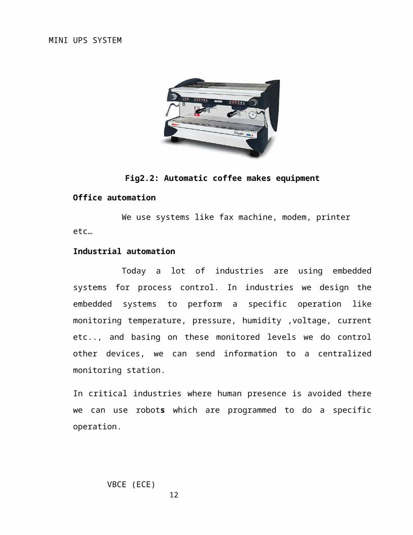
At home we use a number of embedded systems which include microwave oven, remote control, vcd players, dvd players, camera etc….
Fig2.2: Automatic coffee makes equipment
Office automation
VBCE (ECE) 7
Page 8
MINI UPS SYSTEM
We use systems like fax machine, modem, printer etc…
Industrial automation
Today a lot of industries are using embedded systems for process control. In
industries we design the embedded systems to perform a specific operation like monitoring
temperature, pressure, humidity ,voltage, current etc.., and basing on these monitored levels
we do control other devices, we can send information to a centralized monitoring station.
In critical industries where human presence is avoided there we can use robots which are
programmed to do a specific operation.
VBCE (ECE) 8
Page 9
MINI UPS SYSTEM
CHAPTER 3: HARDWARE DESCRIPTION
3.1 Introduction
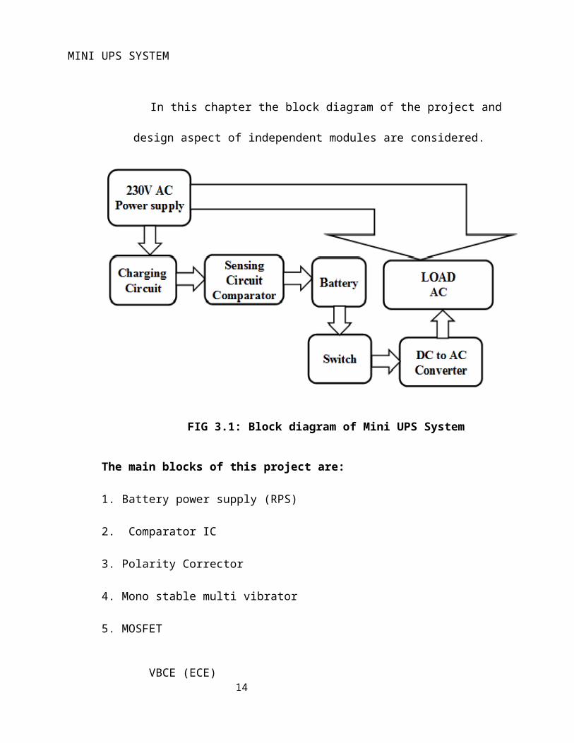
In this chapter the block diagram of the project and design aspect of independent
modules are considered.
FIG 3.1: Block diagram of Mini UPS System
The main blocks of this project are:
1. Battery power supply (RPS)
2. Comparator IC
3. Polarity Corrector
VBCE (ECE) 9
Page 10
MINI UPS SYSTEM
4. Mono stable multi vibrator
5. MOSFET
6. Relay
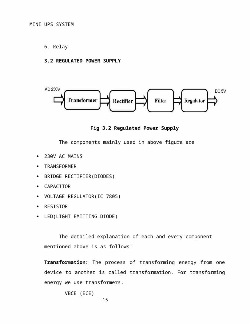
3.2 REGULATED POWER SUPPLY
Fig 3.2 Regulated Power Supply
The components mainly used in above figure are
230V AC MAINS
TRANSFORMER
BRIDGE RECTIFIER(DIODES)
CAPACITOR
VOLTAGE REGULATOR(IC 7805)
RESISTOR
LED(LIGHT EMITTING DIODE)
The detailed explanation of each and every component mentioned above is as
follows:
Transformation: The process of transforming energy from one device to another is called
transformation. For transforming energy we use transformers.
3.2.1 Transformer:
VBCE (ECE) 10
Page 11
MINI UPS SYSTEM
A transformer is a device that transfers electrical energy from one circuit to another
through inductively coupled conductors without changing its frequency. A
varying current in the first or primary winding creates a varying magnetic flux in the
transformer's core, and thus a varying magnetic field through the secondary winding. This
varying magnetic field induces a varying electromotive force (EMF) or "voltage" in the
secondary winding. This effect is called mutual induction.
The input coil is called the PRIMARY WINDING; the output coil is the
SECONDARY WINDING. Fig: 3.3 shows step-down transformer.
Fig 3.3: Step-Down Transformer
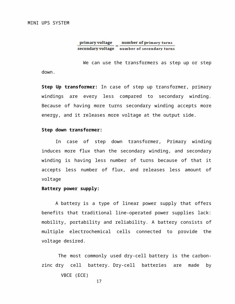
The voltage induced in the secondary is determined by the TURNS RATIO.
We can use the transformers as step up or step down.
Step Up transformer: In case of step up transformer, primary windings are every less
compared to secondary winding. Because of having more turns secondary winding accepts
more energy, and it releases more voltage at the output side.
Step down transformer:
In case of step down transformer, Primary winding induces more flux than the
secondary winding, and secondary winding is having less number of turns because of that it
VBCE (ECE) 11
Page 12
MINI UPS SYSTEM
accepts less number of flux, and releases less amount of voltage
Battery power supply:
A battery is a type of linear power supply that offers benefits that traditional line-
operated power supplies lack: mobility, portability and reliability. A battery consists of
multiple electrochemical cells connected to provide the voltage desired.
The most commonly used dry-cell battery is the carbon-zinc dry cell battery. Dry-
cell batteries are made by stacking a carbon plate, a layer of electrolyte paste, and a zinc
plate alternately until the desired total voltage is achieved. The most common dry-cell
batteries have one of the following voltages: 1.5, 3, 6, 9, 22.5, 45, and 90. During the
discharge of a carbon-zinc battery, the zinc metal is converted to a zinc salt in the
electrolyte, and magnesium dioxide is reduced at the carbon electrode. These actions
establish a voltage of approximately 1.5 V.
The lead-acid storage battery may be used. This battery is rechargeable; it consists
of lead and lead/dioxide electrodes which are immersed in sulfuric acid. During discharge,
the lead is converted to lead sulfate and the sulfuric acid is converted to water. When the
battery is charging, the lead sulfate is converted back to lead and lead dioxide A nickel-
cadmium battery has become more popular in recent years. During the charging process,
nickel oxide is oxidized to its higher oxidation state and cadmium oxide is reduced. The
nickel-cadmium batteries have many benefits. They can be stored both charged and
uncharged. They have a long service life, high current availabilities, constant voltage, and
the ability to be recharged.
Rectification: The process of converting an alternating current to a pulsating direct current
is called as rectification. For rectification purpose we use rectifiers.
3.2.2 Rectifiers: A rectifier is an electrical device that converts alternating current (AC)
to direct current (DC), a process known as rectification. Rectifiers have many uses
including as components of power supplies and as detectors of radio signals. Rectifiers may
be made of solid-state diodes, vacuum tube diodes, mercury arc valves, and other
VBCE (ECE) 12
Page 13
MINI UPS SYSTEM
components. A device that it can perform the opposite function (converting DC to AC) is
known as an inverter.
When only one diode is used to rectify AC (by blocking the negative or positive
portion of the waveform), the difference between the term diode and the term rectifier is
merely one of usage, i.e., the term rectifier describes a diode that is being used to convert
AC to DC. Almost all rectifiers comprise a number of diodes in a specific arrangement for
more efficiently converting AC to DC than is possible with only one diode. Before the
development of silicon semiconductor rectifiers, vacuum tube diodes and copper (I) oxide
or selenium rectifier stacks were used.
Bridge full wave rectifier:
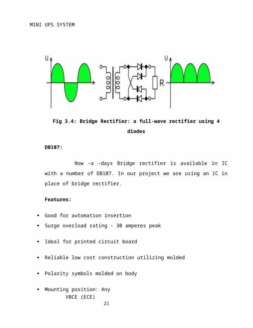
The Bridge rectifier circuit is shown in fig: 3.4, which converts an ac voltage
to dc voltage using both half cycles of the input ac voltage. The Bridge rectifier circuit is
shown in the figure. The circuit has four diodes connected to form a bridge. The ac input
voltage is applied to the diagonally opposite ends of the bridge. The load resistance is
connected between the other two ends of the bridge.
For the positive half cycle of the input ac voltage, diodes D1 and D3
conduct, whereas diodes D2 and D4 remain in the OFF state. The conducting diodes will be
in series with the load resistance RL and hence the load current flows through RL.
For the negative half cycle of the input ac voltage, diodes D2 and D4
conduct whereas, D1 and D3 remain OFF. The conducting diodes D2 and D4 will be in
series with the load resistance RL and hence the current flows through RL in the same
direction as in the previous half cycle. Thus a bi-directional wave is converted into a
unidirectional wave.
Input Output
VBCE (ECE) 13
Page 14
MINI UPS SYSTEM
Fig 3.4: Bridge Rectifier: a full-wave rectifier using 4 diodes
DB107:
Now -a -days Bridge rectifier is available in IC with a number of DB107. In
our project we are using an IC in place of bridge rectifier.
Features:
Good for automation insertion
Surge overload rating - 30 amperes peak
Ideal for printed circuit board
Reliable low cost construction utilizing molded
Polarity symbols molded on body
Mounting position: Any
Weight: 1.0 gram
Filtration:
The process of converting a pulsating direct current to a pure direct current using
filters is called as filtration.
VBCE (ECE) 14
Page 15
MINI UPS SYSTEM
3.2.3 Filters: Electronic filters are electronic circuits, which perform signal-
processing functions, specifically to remove unwanted frequency components from the
signal, to enhance wanted ones.
Regulation:
The process of converting a varying voltage to a constant regulated voltage
is called as regulation. For the process of regulation we use voltage regulators.
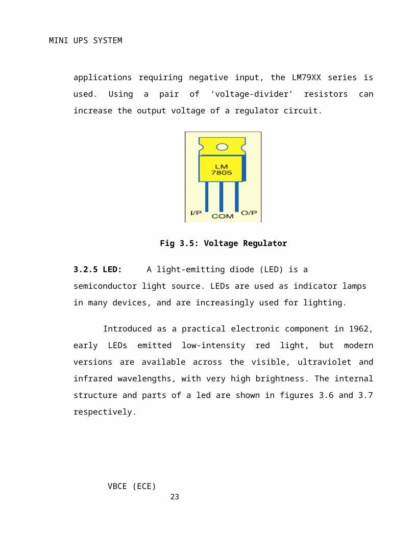
3.2.4 Voltage Regulator:
A voltage regulator (also called a ‘regulator’) with only three terminals
appears to be a simple device, but it is in fact a very complex integrated circuit. It converts
a varying input voltage into a constant ‘regulated’ output voltage. Voltage Regulators are
available in a variety of outputs like 5V, 6V, 9V, 12V and 15V. The LM78XX series of
voltage regulators are designed for positive input. For applications requiring negative input,
the LM79XX series is used. Using a pair of ‘voltage-divider’ resistors can increase the
output voltage of a regulator circuit.
Fig 3.5: Voltage Regulator
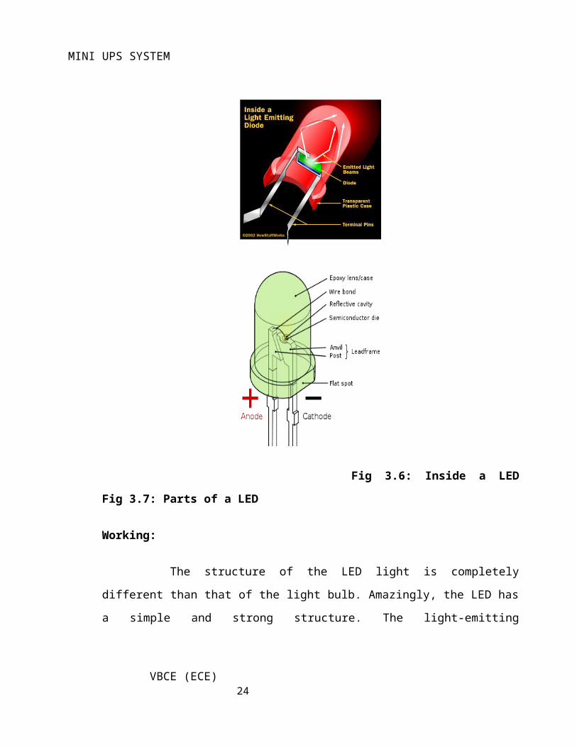
3.2.5 LED: A light-emitting diode (LED) is a semiconductor light source. LEDs are
used as indicator lamps in many devices, and are increasingly used for lighting.
VBCE (ECE) 15
Page 16
MINI UPS SYSTEM
Introduced as a practical electronic component in 1962, early LEDs emitted low-
intensity red light, but modern versions are available across the visible, ultraviolet and
infrared wavelengths, with very high brightness. The internal structure and parts of a led are
shown in figures 3.6 and 3.7 respectively.
Fig 3.6: Inside a LED Fig 3.7: Parts of a LED
Working:
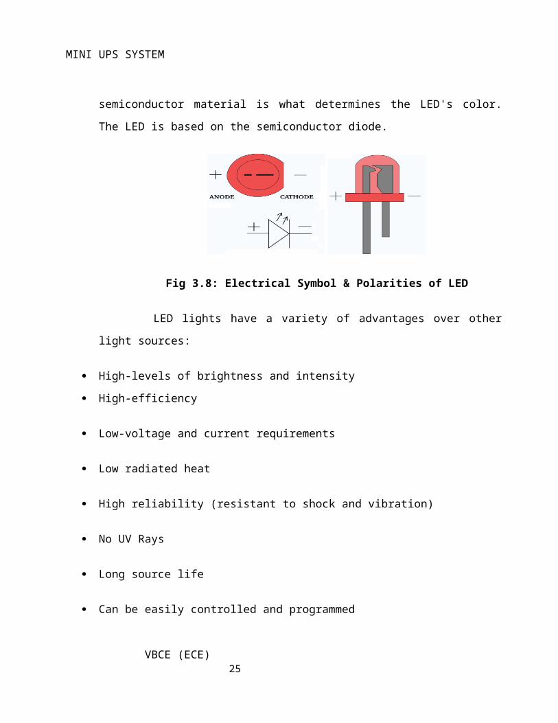
The structure of the LED light is completely different than that of the light
bulb. Amazingly, the LED has a simple and strong structure. The light-emitting
semiconductor material is what determines the LED's color. The LED is based on the
semiconductor diode.
VBCE (ECE) 16
Page 17
MINI UPS SYSTEM
Fig 3.8: Electrical Symbol & Polarities of LED
LED lights have a variety of advantages over other light sources:
High-levels of brightness and intensity
High-efficiency
Low-voltage and current requirements
Low radiated heat
High reliability (resistant to shock and vibration)
No UV Rays
Long source life
Can be easily controlled and programmed
Applications of LED fall into three major categories:
Visual signal application where the light goes more or less directly from the LED to the
human eye, to convey a message or meaning.
Illumination where LED light is reflected from object to give visual response of these
objects.
Generate light for measuring and interacting with processes that do not involve the human
visual system.
3.3 MOSFET
The metal–oxide–semiconductor field-effect transistor (MOSFET, MOS-FET, or
MOS FET) is a transistor used for amplifying or switching electronic signals. Although the
MOSFET is a four-terminal device with source (S), gate (G), drain (D), and body (B)
terminals,[1] the body (or substrate) of the MOSFET often is connected to the source
VBCE (ECE) 17
Page 18
MINI UPS SYSTEM
terminal, making it a three-terminal device like other field-effect transistors. When two
terminals are connected to each other (short-circuited) only three terminals appear in
electrical diagrams. The MOSFET is by far the most common transistor in both digital and
analog circuits, though the bipolar junction transistor was at one time much more common.
In enhancement mode MOSFETs, a voltage drop across the oxide induces a
conducting channel between the source and drain contacts via the field effect. The term
"enhancement mode" refers to the increase of conductivity with increase in oxide field that
adds carriers to the channel, also referred to as the inversion layer.
For the symbols in which the bulk, or body, terminal is shown, it is here shown
internally connected to the source. This is a typical configuration, but by no means the only
important configuration. In general, the MOSFET is a four-terminal device, and in
integrated circuits many of the MOSFETs share a body connection, not necessarily
connected to the source terminals of all the transistors.
3.4 Mono Stable Multi Vibrator
Mono stable multi Vibrator IC CD4047:
IC CD 4047 is mainly used in Inverter circuits. It's very compact and has a very
high life in inverter circuits. CD4047B consists of a gatable astable multi vibrator with
logic techniques incorporated to permit positive or negative edge-triggered mono stable
multi vibrator action with retriggering and external counting options.
Features
1. Lower power consumption: special CMOS oscillator configuration
2. Monostable (one-shot) or astable (free-running) operation
3. True and complemented buffered outputs
Monostable mode
VBCE (ECE) 18
Page 19
MINI UPS SYSTEM
Monostable mode can be obtained by triggering the + input of the IC using a low to high
pulse or by a high to low pulse at the – input. The IC can be retriggered by applying
simultaneous low to high pulse in both the + and – inputs.
Astable mode
This can be obtained by keeping a high / low level at the Astable input. Output frequency
depends on the timing components.
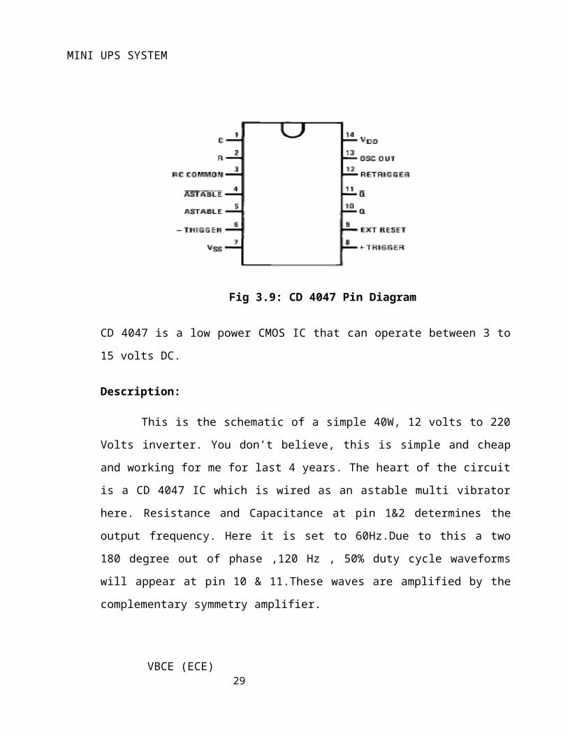
Pin connections of CD4047
Fig 3.9: CD 4047 Pin Diagram
CD 4047 is a low power CMOS IC that can operate between 3 to 15 volts DC.
Description:
This is the schematic of a simple 40W, 12 volts to 220 Volts inverter. You don’t
believe, this is simple and cheap and working for me for last 4 years. The heart of the
circuit is a CD 4047 IC which is wired as an astable multi vibrator here. Resistance and
VBCE (ECE) 19
Page 20
MINI UPS SYSTEM
Capacitance at pin 1&2 determines the output frequency. Here it is set to 60Hz.Due to this
a two 180 degree out of phase ,120 Hz , 50% duty cycle waveforms will appear at pin 10 &
11.These waves are amplified by the complementary symmetry amplifier.
There are three outputs, Q, and OSC out. Q is the normal output, is the inverse of Q
– that is if Q is high, is low – at the same frequency. OSC output provides a signal that is
very close to twice the frequency of Q.
4047 IC Applications
Frequency discriminators
Timing circuits
Time-delay applications
Envelope detection
Frequency multiplication
Frequency division
3.5 LM358 Comparator:
The LM158 (Low Power Dual Operational Amplifiers) series consists of two
independent, high gain; internally frequency compensated operational amplifiers which
were designed specifically to operate from a single power supply over a wide range of
voltages. Operation from split power supplies is also possible and the low power supply
current drain is independent of the magnitude of the power supply voltage.
Application areas include transducer amplifiers, dc gain blocks and all the
conventional op amp circuits which now can be more easily implemented in single power
supply systems.
For example, the LM158 series can be directly operated off of the standard +5V
power supply voltage which is used in digital systems and will easily provide the required
interface electronics without requiring the additional ±15V power supplies.
VBCE (ECE) 20
Page 21
MINI UPS SYSTEM
Connection Diagram
Fig 3.10 Unique Characteristics
In the linear mode the input common-mode voltage range includes ground and the output
voltage can also swing to ground, even though operated from only a single power supply
voltage. The unity gain cross frequency is temperature compensated.
The input bias current is also temperature compensated.
Features:
Internally frequency compensated for unity gain
Large dc voltage gain: 100 dB
Wide bandwidth (unity gain): 1 MHz
(temperature compensated)
Wide power supply range:
Single supply: 3V to 32V
or dual supplies: ±1.5V to ±16V
Very low supply current drain (500 μA)—essentially
independent of supply voltage
Low input offset voltage: 2 mV
VBCE (ECE) 21
Page 22
MINI UPS SYSTEM
Input common-mode voltage range includes ground
Differential input voltage range equal to the power supply voltage
Large output voltage swing: 0V to V+− 1.5V
The LM158 series are op amps which operate with only a single power supply voltage,
have true-differential inputs, and remain in the linear mode with an input common-mode
voltage of 0 VDC. These amplifiers operate over a wide range of power supply voltage
with little change in performance characteristics. At 25°C amplifier operation is possible
down to a minimum supply voltage of 2.3 VDC.
Advantages:
Two internally compensated op amps in single packages.
Eliminates need for dual supplies
Allows directly sensing near GND and VOUT also goes to GND
Compatible with all forms of logic
Power drain suitable for battery operation
Pin-out same as LM1558/LM1458 dual operational amplifier
3.6 Relay
A relay is an electrically operated switch. Many relays use an electromagnet to
operate a switching mechanism, but other operating principles are also used. Relays find
applications where it is necessary to control a circuit by a low-power signal, or where
several circuits must be controlled by one signal. The first relays were used in long distance
telegraph circuits, repeating the signal coming in from one circuit and re-transmitting it to
another. Relays found extensive use in telephone exchanges and early computers to
perform logical operations. Relays with calibrated operating characteristics and sometimes
multiple operating coils are used to protect electrical circuits from overload or faults; in
modern electric power systems these functions are performed by digital instruments still
called "protection relays".
Advantages of relays:
VBCE (ECE) 22
Page 23
MINI UPS SYSTEM
Relays can switch AC and DC, transistors can only switch DC.
Relays can switch high voltages, transistors cannot.
Relays are a better choice for switching large currents (> 5A).
Relays can switch many contacts at once.
Disadvantages of relays:
Relays are bulkier than transistors for switching small currents.
Relays cannot switch rapidly (except reed relays), transistors can switch many times
per second.
Relays use more power due to the current flowing through their coil.
Relays require more current than many ICs can provide, so a low power transistor
may be needed to switch the current for the relay's coil.
Relay Driver:
The current needed to operate the relay coil is more than can be supplied by most
chips (op. amps etc), so a transistor is usually needed, as shown in the diagram below.
Use BC109C or similar. A resistor of about 4k7 will probably be alright. The diode
is needed to short circuit the high voltage “back emf” induced when current flowing
through the coil is suddenly switched off.
VBCE (ECE) 23
Page 24
MINI UPS SYSTEM
Fig. 3.11 Relay Driver
CHAPTER 4: PROJECT DESCRIPTION
In this chapter, schematic diagram and interfacing of components to IC 1CD4047,
comparator IC, battery, bulbs are considered.
VBCE (ECE) 24
Page 25
MINI UPS SYSTEM
Fig 4.1: Schematic diagram of Mini UPS
Inverter Working Procedure:
Inverter circuit using CD 4047:
CD 4047 is used for generating the 100 Hz pulses and four 2N3055 transistors for driving
the load. The IC1 Cd4047 wired astable multi vibrator produces two 180 degree out of
phase 100 Hz pulse trains. These pulse trains are pre amplified by the two TIP122
transistors. The out puts of the TIP 122 transistors are amplified by four 2N3055 transistors
(two transistors for each half cycle) to drive the inverter transformer. The 220V AC will be
available at the secondary of the transformer.
VBCE (ECE) 25
Page 26
MINI UPS SYSTEM
4.1 Description:
A 12 V car battery can be used as the 12V source.
Use the POT R1 to set the output frequency to50Hz.
For the transformer get a 12-0-12 V, 10A step down transformer. But here the 12-
0-12 V winding will be the primary and 220V winding will be the secondary.
For 10A rated transformer, we get a 5A output. But the allowed out put power will be
reduced to 60W. Use a 10 A fuse in series with the battery.
Mount the IC on a IC holder.
CHAPTER 5: ADVANTAGES AND DISADVANTAGES
VBCE (ECE) 26
Page 27
MINI UPS SYSTEM
5.1 Advantages:
1. This system helps in providing uninterrupted power supply.
2. Usage of rechargeable battery.
3. Inverter circuit design
4. Efficient and low cost design.
5. Easy to operate.
5.2 Disadvantages:
1. This system requires periodic monitoring and maintenance.
2. This system fails to work if the load is heavy.
3. Status of operated devices is not known.
5.3 Applications:
This system can be practically implemented in real time in Industrial applications, batteries,
vehicles, mining.
Houses etc.,
CHAPTER 6: RESULTS
VBCE (ECE) 27
Page 28
MINI UPS SYSTEM
6.1 Result:
The project “Mini UPS System” was to design a mini UPS system
with inverter design.
6.2 Conclusion:
Integrating features of all the hardware components used have been
developed in it. Presence of every module has been reasoned out and placed carefully, thus
contributing to the best working of the unit. Secondly, using highly advanced IC’s with the
help of growing technology, the project has been successfully implemented. Thus the
project has been successfully designed and tested.
6.3 Future Scope:
Our project “Mini UPS System” is mainly intended to design a mini UPS
system. This project uses comparator IC to detect the over load, an inverter for DC to AC
conversion, charging on and battery low conditions. CFL loads are suggested for this
project, as they consume low power and produce high intensity of lighting.
These inverters play vital role especially in rural areas. A rechargeable 12V battery
is used to store the energy during power availability. The back up time depends on the
battery ampere – hour rating. This inverter can show the battery low condition and over
conditions by 5mm LED indicator circuit.
The battery is connected to the inverter. This inverter is used to convert the 12volt
DC to the 230 Volt AC. This 230 volt AC voltage is used to activate the loads. Here we are
also using conventional battery charger unit to recharge the battery. In this project we are
using regulated 5v, 750mA power supply for microcontroller unit. 7805 three terminal
voltage regulator is used for voltage regulation. Bridge type full wave rectifier is used to
rectify the AC output of secondary of 230/12v step down transformer.
VBCE (ECE) 28
Page 29
MINI UPS SYSTEM
The main draw back of this system is it can draw only limited energy this can be
eliminated by maximum power generation. The hydel power plant requires water flow
continuously.
The maximum allowed output power of an inverter depends on two factors.
1. The maximum current rating of the transformer primary and the current rating of the
driving transistors.
2. For example ,to get a 100 Watt output using 12 V car battery the primary current will be
~8A ,(100/12) because P=VxI. So the primary of transformer must be rated above 8A.
3. Also here, each final driver transistors must be rated above 4A. Here two will be
conducting parallel in each half cycle, so I=8/2 = 4A.
VBCE (ECE) 29
Page 30
MINI UPS SYSTEM
REFERENCES
The sites which were used while doing this project:
1. www.wikipedia.com
2. www.electronicforu.com
3. www.allaboutcircuits.com
Books referred:
1. Electronics for You- Garrett - OKM - Minelab Authorised
2. Basic Skills: Electronics by Tom Duncan
3. Electronics-A First Course by Owen Bishop
VBCE (ECE) 30