Keywords: Boiler water level; Cascade control; Generalized predictive control; PID control
ri-ve
n-dlthepin-of-
rere
nseater
e-he
e--n-ingn-
riesed-nnc-
1. Introduction
In boiler plants, there are several process vaables, such as main steam temperature, drum leand stack gas oxygen content@1#. Among them,the drum level is an important variable to be cotrolled such that it is within the pre-specifiesafety limits. In practice, this is a difficult controtask due to the existence of constraints onamount of feedwater flow dictated by the pumrating, parameter uncertainties, and modelingaccuracies@2,3#. Cascade control schemes areten adopted to overcome these difficulties@4–6#:
• Disturbances arising in the inner loop acorrected by the same loop controller befothey influence system output variable.
• The speed and accuracy of system respois much improved if the inner loop exhibitsfaster dynamic response than that of ouloop.
• The inner feedback control loop can also rduce the effect of parameter variations in tinner loop.
Conventionally, the cascade proportional intgral differential~PID! approach is usually implemented for drum level control. However, this cotrol scheme may be unsatisfactory when dealwith processes with large time delay and costraints.
Today, model predictive control~MPC! has re-ceived wide acceptance in the process industbecause of its time domain, optimization-basformulation, and natural ability to handle constraints@7#. The advantage of MPC is that it casolve simultaneously control and optimizatioproblems. As an optimizer, it maximizes a produ
mentation, Systems, and Automation Society.
400 Min Xu, Shaoyuan Li, Wenjian Cai / ISA Transactions 44 (2005) 399–411
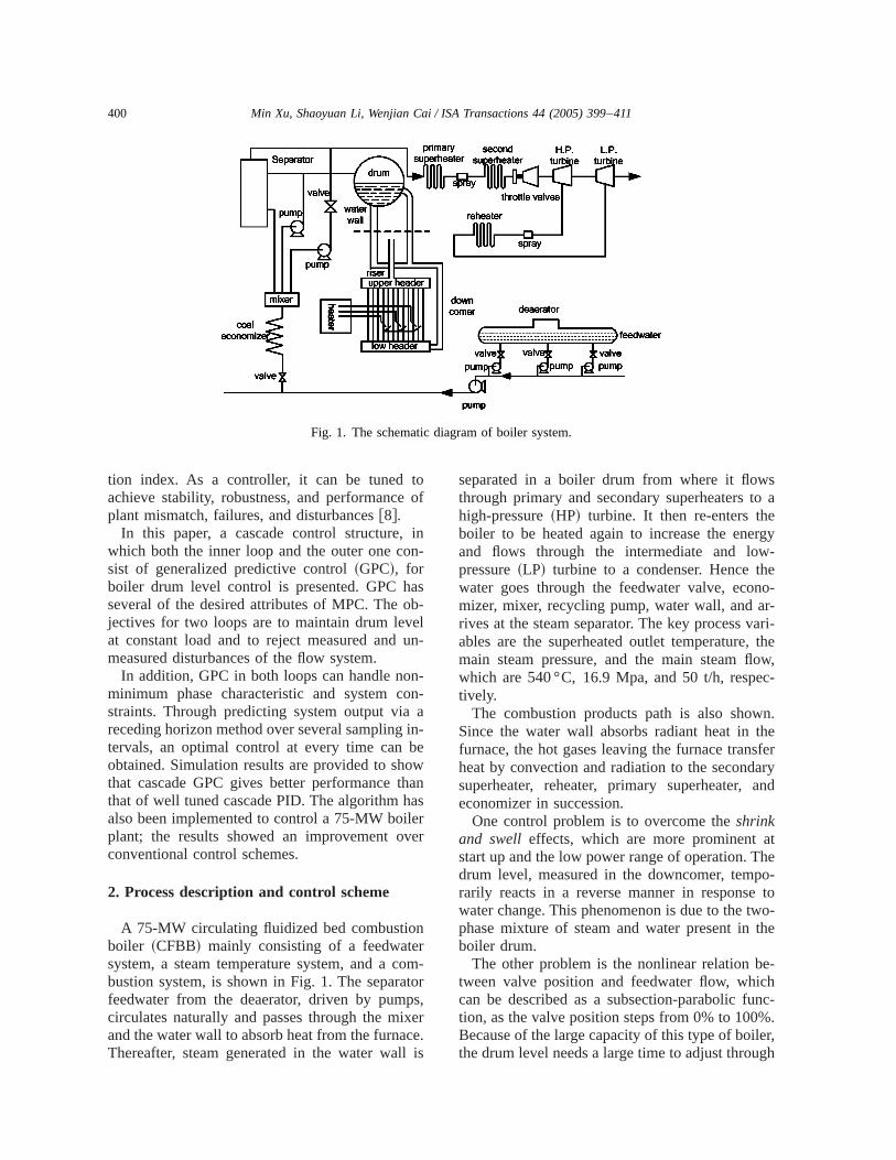
Fig. 1. The schematic diagram of boiler system.
toof
inn-
asb-elun
n-on-
ain-beowhanaserer
nromtorps,xerce.l is
so aergy-e
no-r-ari-the
ow,-
n.hesferaryand
theo-too-
the
e-hnc-
%.er,gh
tion index. As a controller, it can be tunedachieve stability, robustness, and performanceplant mismatch, failures, and disturbances@8#.
In this paper, a cascade control structure,which both the inner loop and the outer one cosist of generalized predictive control~GPC!, forboiler drum level control is presented. GPC hseveral of the desired attributes of MPC. The ojectives for two loops are to maintain drum levat constant load and to reject measured andmeasured disturbances of the flow system.
In addition, GPC in both loops can handle nominimum phase characteristic and system cstraints. Through predicting system output viareceding horizon method over several samplingtervals, an optimal control at every time canobtained. Simulation results are provided to shthat cascade GPC gives better performance tthat of well tuned cascade PID. The algorithm halso been implemented to control a 75-MW boilplant; the results showed an improvement ovconventional control schemes.
2. Process description and control scheme
A 75-MW circulating fluidized bed combustioboiler ~CFBB! mainly consisting of a feedwatesystem, a steam temperature system, and a cbustion system, is shown in Fig. 1. The separafeedwater from the deaerator, driven by pumcirculates naturally and passes through the miand the water wall to absorb heat from the furnaThereafter, steam generated in the water wal
-
-
separated in a boiler drum from where it flowthrough primary and secondary superheaters thigh-pressure~HP! turbine. It then re-enters thboiler to be heated again to increase the eneand flows through the intermediate and lowpressure~LP! turbine to a condenser. Hence thwater goes through the feedwater valve, ecomizer, mixer, recycling pump, water wall, and arives at the steam separator. The key process vables are the superheated outlet temperature,main steam pressure, and the main steam flwhich are540 °C, 16.9 Mpa, and 50 t/h, respectively.
The combustion products path is also showSince the water wall absorbs radiant heat in tfurnace, the hot gases leaving the furnace tranheat by convection and radiation to the secondsuperheater, reheater, primary superheater,economizer in succession.
One control problem is to overcome theshrinkand swell effects, which are more prominent astart up and the low power range of operation. Tdrum level, measured in the downcomer, temprarily reacts in a reverse manner in responsewater change. This phenomenon is due to the twphase mixture of steam and water present inboiler drum.
The other problem is the nonlinear relation btween valve position and feedwater flow, whiccan be described as a subsection-parabolic fution, as the valve position steps from 0% to 100Because of the large capacity of this type of boilthe drum level needs a large time to adjust throu
401Min Xu, Shaoyuan Li, Wenjian Cai / ISA Transactions 44 (2005) 399–411
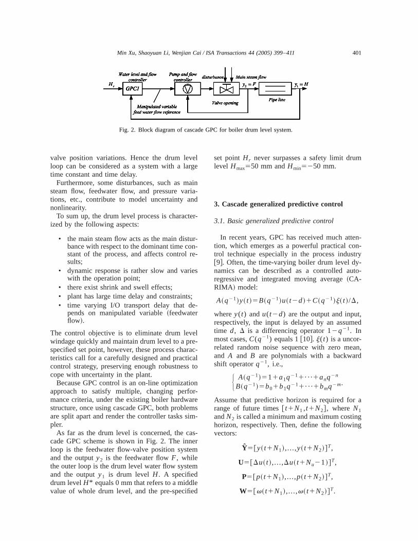
Fig. 2. Block diagram of cascade GPC for boiler drum level system.
elrge
ainia-nd
er-
ur-n-re-
ies
;-
ele-racalto
onr-rem
im-
as-erm
m
leed
m
en-n-try-to-
,ed
an,
a
gg
valve position variations. Hence the drum levloop can be considered as a system with a latime constant and time delay.
Furthermore, some disturbances, such as msteam flow, feedwater flow, and pressure vartions, etc., contribute to model uncertainty anonlinearity.
To sum up, the drum level process is charactized by the following aspects:
• the main steam flow acts as the main distbance with respect to the dominant time costant of the process, and affects controlsults;
• dynamic response is rather slow and varwith the operation point;
• there exist shrink and swell effects;• plant has large time delay and constraints• time varying I/O transport delay that de
pends on manipulated variable~feedwaterflow!.
The control objective is to eliminate drum levwindage quickly and maintain drum level to a prspecified set point, however, these process chateristics call for a carefully designed and practiccontrol strategy, preserving enough robustnesscope with uncertainty in the plant.
Because GPC control is an on-line optimizatiapproach to satisfy multiple, changing perfomance criteria, under the existing boiler hardwastructure, once using cascade GPC, both probleare split apart and render the controller tasks spler.
As far as the drum level is concerned, the ccade GPC scheme is shown in Fig. 2. The innloop is the feedwater flow-valve position systeand the outputy2 is the feedwater flowF, whilethe outer loop is the drum level water flow systeand the outputy1 is drum levelH. A specifieddrum levelH* equals 0 mm that refers to a middvalue of whole drum level, and the pre-specifi
-
s
set pointHr never surpasses a safety limit drulevel Hmax550 mmandHmin5250 mm.
3. Cascade generalized predictive control
3.1. Basic generalized predictive control
In recent years, GPC has received much atttion, which emerges as a powerful practical cotrol technique especially in the process indus@9#. Often, the time-varying boiler drum level dynamics can be described as a controlled auregressive and integrated moving average~CA-RIMA ! model:
A~q21!y~ t !5B~q21!u~ t2d!1C~q21!j~ t !/D,
wherey(t) andu(t2d) are the output and inputrespectively, the input is delayed by an assumtime d, D is a differencing operator12q21. Inmost cases,C(q21) equals 1@10#. j(t) is a uncor-related random noise sequence with zero meand A and B are polynomials with a backwardshift operatorq21, i.e.,
H A~q21!511a1q211¯1anq2n
B~q21!5b01b1q211¯1bmq2m.
Assume that predictive horizon is required forrange of future times@ t1N1 ,t1N2#, where N1andN2 is called a minimum and maximum costinhorizon, respectively. Then, define the followinvectors:
Y5@y~ t1N1!,...,y~ t1N2!#T,
U5@Du~ t !,...,Du~ t1Nu21!#T,
P5@p~ t1N1!,...,p~ t1N2!#T,
W5@v~ t1N1!,...,v~ t1N2!#T.
p-
curoer,
e
,
m.e-
g
on-
pt
402 Min Xu, Shaoyuan Li, Wenjian Cai / ISA Transactions 44 (2005) 399–411
Therefore system predictive output can be reresented by the following equation:
Y5GU1P,
where
G5F gN1gN121 ¯ 0 0
gN111 gN1gN121 ¯ 0
A A A A AgN221 gN222 ¯ ¯ gN22Nu
gN2gN221 gN222 ¯ gN22Nu11
G .
The elementsgi of a matrixG, being points onthe plant’s step response, can be computed resively from the CARIMA model assuming a zernoise and a constant unit control input. Moreova free responseP(t1 j ) can be simply calculatedfor all j by iterating plant model, and a futurcontrol equals the previous control variableu(t21).
Considering a multistage cost function
JGPC5 (j 5N1
N2
@y~ t1 j !2v~ t1 j !#2
1 (j 51
Nu
lDu2~ t1 j 21!,
where v(t1 j ) is a future reference trajectorywhich is a pre-specified set pointyr(t), andl is aweighting upon future control increments,
H v~ t !5y~ t ! j 51,...,Nv~ t1 j !5av~ t1 j 21!1~12a!yr~ t !. ~1!
For simplicity, let N5N22N1 , a is a softenfactor aP@0,1#.
Hence the cost function can be written
JGPC5~GU1P2W!T~GU1P2W!1lUTU.
The solution minimizingJGPC gives an optimalsuggested control increment sequenceUopt :
Uopt5~GTG1lIN!21GT1~W2P!.
The first output ofUopt is Du(t), and the actualcontrol to be applied isu(t)5u(t21)1Du(t).
-
3.2. Cascade generalized predictive control
Two loops are included in cascade GPC systeTherefore the cost function of each loop is dfined:
JG1~N11,N21,Nu1!
5 (j 5N11
N21
@ y1~ t1 j !2v1~ t1 j !#2
1 (j 51
Nu1
l1~ j !@Du1~ t1 j 21!#2, ~2!
JG2~N12,N22,Nu2!
5 (j 5N12
N22
@ y2~ t1 j !2v2~ t1 j !#2
1 (j 51
Nu2
l2~ j !@Du2~ t1 j 21!#2. ~3!
Assume thatDu1(t1 j )50 for j >Nu1 andDu2(t1 j )50 for j >Nu2 . In order to get an op-timal control sequence$u1% betweenN11 andN21,we should minimize the cost functionJG1 . More-over, from N12 to N22, the optimal control se-quence$u2% is to be achieved through minimizinthe criterionJG2 . It is true that the timeN21 islarger thanN22.
Even as the standard generalized predictive ctrol, Eqs. ~2! and ~3! can be written with matrixform:
H Y15G1U11P1
Y25G2U21P2, ~4!
where
Y15@y1~ t1N11!,...,y1~ t1N111N2121!#T,
Y25@y2~ t1N12!,...,y2~ t1N121N2221!#T,
U15@Du1~ t !,...,Du1~ t1Nu121!#T,
U25@Du2~ t !,...,Du2~ t1Nu221!#T,
P15@p1~ t1N11!,...,p1~ t1N21!#T,
P25@p2~ t1N12!,...,p2~ t1N22!#T.
As seen in Fig. 2, we know that the outer loocontrol variableU2 equals the inner loop set poin
403Min Xu, Shaoyuan Li, Wenjian Cai / ISA Transactions 44 (2005) 399–411
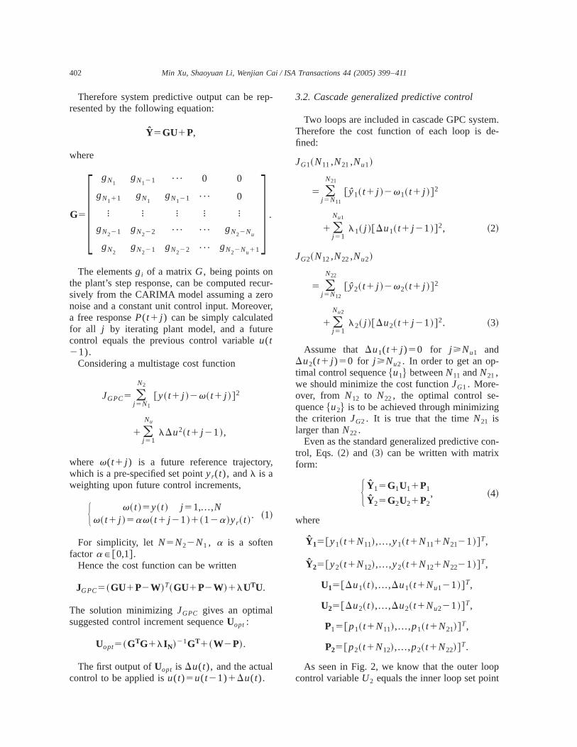
Fig. 3. Simulation module diagram.
ix.
s
b-
en
-
le
e
tt
ter
v2 , and the outer loop oneY1 should track setpoint v1 . G1 andG2 are the step response matrof the external and internal system respectively
The future reference trajectoryv1 and v2 ,which is similar to Eq.~1!, is
H v15@v1~ t1N11!,...,v1~ t1N21!#T
v25@v2~ t1N12!,...,v2~ t1N22!#T.
Substituting Eq.~4! into Eqs.~2! and ~3!,
JG15~G1U11P12v1!T~G1U11P12v1!
1l1U1TU1 ,
JG25~G2U21P22v2!T~G2U21P22v2!
1l2U2TU2 .
Finally, through computing the equation]JG1 /]U150 and ]JG2 /]U250, the generalizedsystem optimal control variables are to be otained:
H Uopt15~G1TG11l1IN11
!21G1T~v12P1!
Uopt25~G2TG21l2IN22
!21G2T~v22P2!
. ~5!
The proposed cascade GPC algorithm is givas follows:Step 1:Set a sample time of two loopsT1 andT2 .Step 2: Set a maximum, minimum predictive horizon and control horizon for two loops.Step 3:Estimate CARIMA model to yieldG1 ,G2andP1 ,P2 .Step 4: Compute matrix G1 ,G2 and (G1
TG1
1l1IN11)21,(G2
TG21l2IN22)21.
Step 5: Determine control variableUopt1 ,Uopt2based on Eq.~5!.Step 6: Setk5k11, go back step 3.
As a matter of fact, there is no particular ruthat enables an optimal choice ofN11,N21,N12,N22; Nu1 ,Nu2 ; and l1 ,l2 . Moreover, it ispossible to note following three points:
• It is better to chooseN11,N12, so that atleast one element of the first row ofG1 ,G2is nonzero.N11,N12 should be greater thanthe maximum expected time delay of thprocess.
• Very often Nui( i 51,2) is chosen so thaNui!N2i ( i 51,2) and we stressed the facNui51( i 51,2) is very interesting.
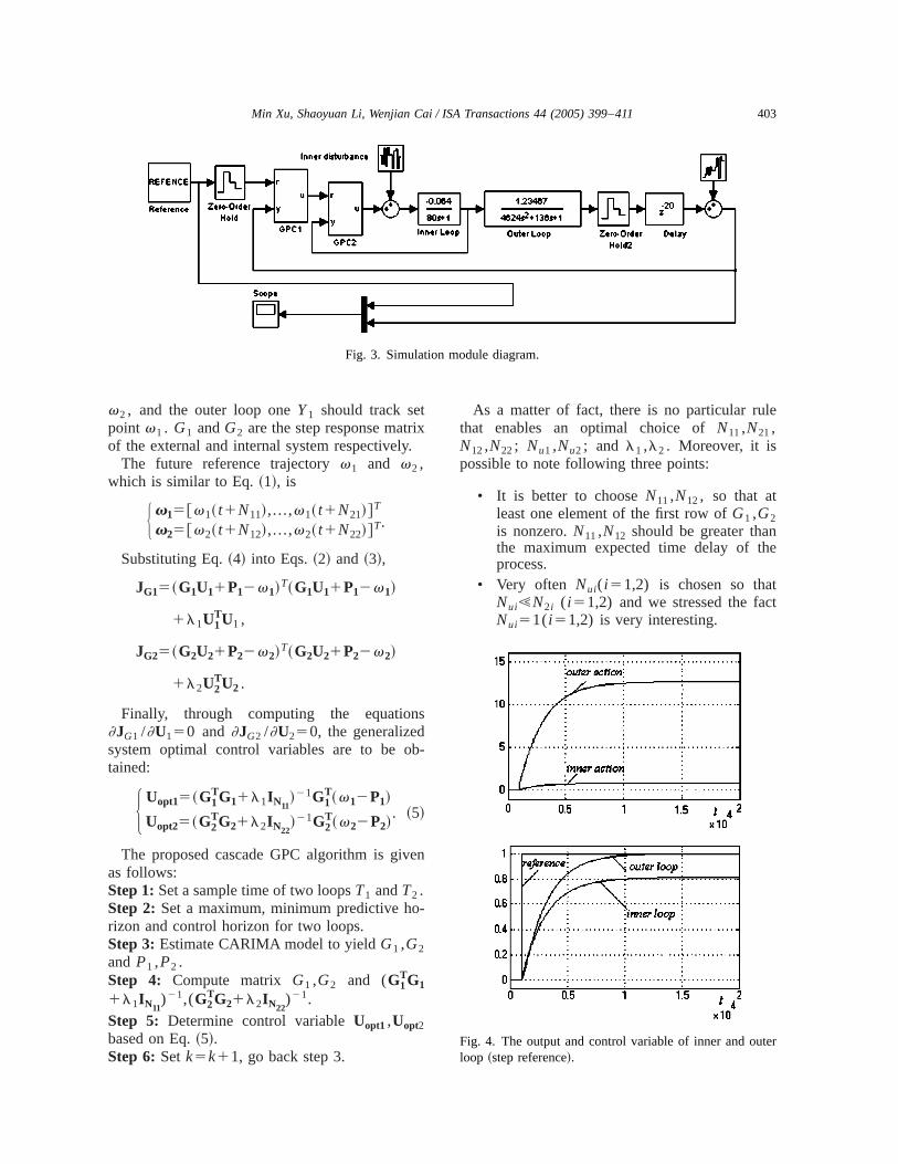
Fig. 4. The output and control variable of inner and ouloop ~step reference!.
If
ix
re-sfelegero-vels,
-rem:
t
eheef
-
rened
de
e-
nd p
404 Min Xu, Shaoyuan Li, Wenjian Cai / ISA Transactions 44 (2005) 399–411
• l1 and l2 are often hard to determine.matrix G1
TG1 andG2TG2 are itself invertible,
evenl15l250 can give a solution. But inmost cases, it seems better to choosel1 ,l2very small but nonzero, so that the matr(G1
TG11l1IN11)21 and (G2
TG21l2IN22)21
become invertible.
4. Simulation example
In many processes, the plant can often begarded as a cascade system, in which the tranfunction in the inner loop has no or a negligibtime delay, while the outer loop one has a lartime delay. To show the effectiveness of the pposed method, we use a reduction drum lemodel for inner and outer loop transfer functiongiven as follows@11#:
Gp2520.064
1180sand Gp15
1.23467
~1168s!2e220s .
The SIMULINK module in the mathematic software MATLAB is shown in Fig. 3. Parameters asettled for configuring the cascade GPC algorith
Fig. 5. The output and control action of inner loop aouter loop~square wave reference!.
r
• The time constant of the inner loop isTs580 s,while that of the outer loop is almosTs5136 s.
• In order to show interaction effects, multiplrates sample time should be considered. Trule of thumb is that outer loop sample timT1 is five times to ten times than that oinner loop T2 . Hence letT158 s and T251 s.
• Weighting on control variable isl150.7andl250.5, respectively, and a soften factor for both loops isa50.6. If choosing ahigher value ofl1 ,l2 coefficient, the con-trol system becomes more robust. Therefoa tradeoff value between control actioweights and soften factors can be designto obtain a satisfactory performance.
• In the inner loop,N1151 andN2156, whilein the outer loop, parameters areN1253 andN22510.
• Suppose that noise variance is 0.01.
Figs. 4–10 show different responses of cascaGPC based on different types of set points.
First, we let the set point equal the step squence~shown in Fig. 4!. In order to examine the
Fig. 6. The output of inner loop and outer loop with ramincrease reference.
ned
eotlts
lizei-
n-theltslyty.
oml PIngf
est
mes aut-0%ich
isad-toed
nonem-trol
-esal-
-
r
p
ter
405Min Xu, Shaoyuan Li, Wenjian Cai / ISA Transactions 44 (2005) 399–411
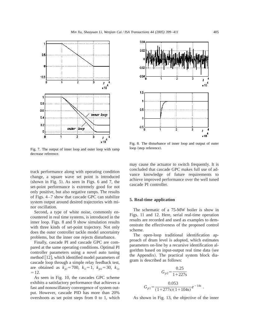
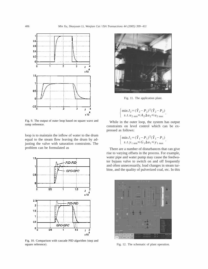
track performance along with operating conditiochange, a square wave set point is introduc~shown in Fig. 5!. As seen in Figs. 6 and 7, thset-point performance is extremely good for nonly positive, but also negative ramps. The resuof Figs. 4–7 show that cascade GPC can stabisystem output around desired trajectories with mnor oscillation.
Second, a type of white noise, commonly ecountered in real time systems, is introduced ininner loop. Figs. 8 and 9 show simulation resuwith three kinds of set-point trajectory. Not ondoes the outer controller tackle model uncertainproblems, but the inner one rejects disturbance
Finally, cascade PI and cascade GPC are cpared at the same operating conditions. Optimacontroller parameters using a novel auto tunimethod@12#, which identified model parameters ocascade loop through a simple relay feedback tare obtained askpi5700, kii 51, kpo530, kio
512.As seen in Fig. 10, the cascades GPC sche
exhibits a satisfactory performance that achievefast and nonoscillatory convergence of system oput. However, cascade PID has more than 2overshoots as set point steps from 0 to 1, wh
Fig. 7. The output of inner loop and outer loop with ramdecrease reference.
-
,
may cause the actuator to switch frequently. Itconcluded that cascade GPC makes full use ofvance knowledge of future requirementsachieve improved performance over the well tuncascade PI controller.
5. Real-time application
The schematic of a 75-MW boiler is show iFigs. 11 and 12. Here, serial real-time operatiresults are recorded and used as examples to donstrate the effectiveness of the proposed conscheme.
The open-loop traditional identification approach of drum level is adopted, which estimatparameters on-line by a recursive identificationgorithm based on input-output real time data~seethe Appendix!. The practical system block diagram is described as follows:
Gp250.25
11227s
Gp150.053
~11277s!~11104s!e214s .
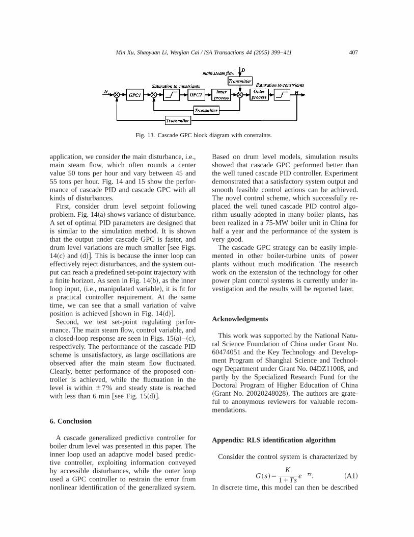
As shown in Fig. 13, the objective of the inne
Fig. 8. The disturbance of inner loop and output of ouloop ~step reference!.
d-he
utx-
ivele,wa-tlytur-is
and
406 Min Xu, Shaoyuan Li, Wenjian Cai / ISA Transactions 44 (2005) 399–411
loop is to maintain the inflow of water to the drumequal to the steam flow leaving the drum by ajusting the valve with saturation constraints. Tproblem can be formulated as
Fig. 9. The output of outer loop based on square waveramp reference.
Fig. 10. Comparison with cascade PID algorithm~step andsquare reference!.
H minJ25~Y22P2!T~Y22P2!s.t.u2 min<A2Du2<u2 max
.
While in the outer loop, the system has outpconstraints on level control which can be epressed as follows:
H minJ15~Y12P1!T~Y12P1!s.t.y1 min<G1Du1<y1 max
.
There are a number of disturbances that can grise to varying offsets in the process. For exampwater pipe and water pump may cause the feedter bypass valve to switch on and off frequenand often unnecessarily, load changes in steambine, and the quality of pulverized coal, etc. In th
Fig. 11. The application plant.
Fig. 12. The schematic of plant operation.
407Min Xu, Shaoyuan Li, Wenjian Cai / ISA Transactions 44 (2005) 399–411
Fig. 13. Cascade GPC block diagram with constraints.
.e.,ternd
or-al
ge.hatnand
nut-ith
eve
r-nd
IDared.n-
ed
orheic-
dopmm.
ltshannt
anded.re-o-
asris
le-r
chern-r.
u-o.p-ol-ndhea--
by
ed
application, we consider the main disturbance, imain steam flow, which often rounds a cenvalue 50 tons per hour and vary between 45 a55 tons per hour. Fig. 14 and 15 show the perfmance of cascade PID and cascade GPC withkinds of disturbances.
First, consider drum level setpoint followinproblem. Fig. 14~a! shows variance of disturbancA set of optimal PID parameters are designed tis similar to the simulation method. It is showthat the output under cascade GPC is faster,drum level variations are much smaller@see Figs.14~c! and ~d!#. This is because the inner loop caeffectively reject disturbances, and the system oput can reach a predefined set-point trajectory wa finite horizon. As seen in Fig. 14~b!, as the innerloop input,~i.e., manipulated variable!, it is fit fora practical controller requirement. At the samtime, we can see that a small variation of valposition is achieved@shown in Fig. 14~d!#.
Second, we test set-point regulating perfomance. The main steam flow, control variable, aa closed-loop response are seen in Figs. 15~a!–~c!,respectively. The performance of the cascade Pscheme is unsatisfactory, as large oscillationsobserved after the main steam flow fluctuateClearly, better performance of the proposed cotroller is achieved, while the fluctuation in thlevel is within 67% and steady state is reachewith less than 6 min@see Fig. 15~d!#.
6. Conclusion
A cascade generalized predictive controller fboiler drum level was presented in this paper. Tinner loop used an adaptive model based predtive controller, exploiting information conveyeby accessible disturbances, while the outer loused a GPC controller to restrain the error frononlinear identification of the generalized syste
l
Based on drum level models, simulation resushowed that cascade GPC performed better tthe well tuned cascade PID controller. Experimedemonstrated that a satisfactory system outputsmooth feasible control actions can be achievThe novel control scheme, which successfullyplaced the well tuned cascade PID control algrithm usually adopted in many boiler plants, hbeen realized in a 75-MW boiler unit in China fohalf a year and the performance of the systemvery good.
The cascade GPC strategy can be easily impmented in other boiler-turbine units of poweplants without much modification. The researwork on the extension of the technology for othpower plant control systems is currently under ivestigation and the results will be reported late
Acknowledgments
This work was supported by the National Natral Science Foundation of China under Grant N60474051 and the Key Technology and Develoment Program of Shanghai Science and Technogy Department under Grant No. 04DZ11008, apartly by the Specialized Research Fund for tDoctoral Program of Higher Education of Chin~Grant No. 20020248028!. The authors are grateful to anonymous reviewers for valuable recommendations.
Appendix: RLS identification algorithm
Consider the control system is characterized
G~s!5K
11Tse2ts. ~A1!
In discrete time, this model can then be describ
408 Min Xu, Shaoyuan Li, Wenjian Cai / ISA Transactions 44 (2005) 399–411
Fig. 14. ~a!–~e! water level with following under varying main steam flow disturbance.
409Min Xu, Shaoyuan Li, Wenjian Cai / ISA Transactions 44 (2005) 399–411
Fig. 15. ~a!–~e! water level with regulating under varying main steam flow disturbance.
utissti-are
h-
r is
b-
r2th
a-
ens.
g
aler-p.
as-
re-
-
l-,
ica
al-
0.r-
410 Min Xu, Shaoyuan Li, Wenjian Cai / ISA Transactions 44 (2005) 399–411
y~kh!5ay~kh2h!1b1u~kh2h!
1b2u~kh22h!, ~A2!
whereh is the sampling period, and
H a5e2h/T
b15K~12e2(h2t)/T!b25Ke2h/T~et/T21!
. ~A3!
For arbitrary time delayt, the model becomes
y~kh!5ay~kh2h!1b1u@~k2n!h#
1b2u@~k2n21!h#, ~A4!
wheren5mod(t/h).This form can be extended to higher order:
y~kh!1a1y~kh2h!1¯1any~kh2nh!
5b1u~kh2h!1¯1bnu~kh2nh!. ~A5!
This equation can be written compactly as
A~q!y~kh!5B~q!u~kh!, ~A6!
where
H A~q!5qn1a1qn211¯1an
B~q!5b1qn211b2qn221¯1bn. ~A7!
In the identification experiment, the input/outppair is normally obtained in each sampling, itthen convenient to compute the parameter emates recursively, and all the parametersgrouped in the vector
u5~a1 ,a2 ,...,an ,b1 ,...,bn!T,
and introduce the regression vector defined by
wk215 S 2y~kh2h!,...,2y~kh2nh!,u~kh2h!,...,u~kh2nh! D T
.
The estimate can be calculated recursively by
5ek5y~kh!2wk21
T uk21
Pk5Pk212Pk21wk21wk21
T Pk21
11wk21T Pk21wk21
uk5uk211Pkwk21ek
. ~A8!
The RLS algorithm can be extend to the higorder system whose model is given as follows:
Therefore the identify parameters can be otained by Eq.~A6! through substituting Eq.~A10!into Eq. ~A7!.
References
@1# Astrom, K. J. and Bell, R. D., A nonlinear model fosteam generation process. Proceedings of the 1World Congress of IFAC, 1993, pp. 395–398.
@2# Flynn, M. E. and O’Malley, M. J., A drum boilermodel for long term power system dynamic simultion. IEEE Trans. Power Appar. Syst.14~1!, 209–217~1999!.
@3# Mayuresh, V. K. and Bernard, M., Level control in thsteam generator of a nuclear power plant. IEEE TraControl Syst. Technol.8~1!, 55–69~2000!.
@4# Song, S. H., Cai, W. J., and Wang, Y. G., Auto-tuninof cascade control systems. ISA Trans.42~3!, 63–72~2003!.
@5# Wang, F. S., Juang, W. S., and Chan, C. T., Optimtuning of cascade PID control systems. IEEE Confence on Control Applications, 13–16 Sept. 1993, p825–828.
@6# Byung, S. K. and ThomasEdgar, F., Performancesessment of cascade control loops. AIChE J.46~5!,281–291~2000!.
@7# Richalet, J., Industrial application of model based pdictive control. Automatica29~5!, 1251–1274~1993!.
@8# Maciejowski, J. M., Predictive Control with Constraints. Prentice-Hall, Englewood Cliffs, NJ, 2001.
@9# Clarke, D. W., Mohtadi, C., and Tuffs, P. S., Generaized predictive control, Part 1: The basic algorithmand Part 2: Extensions and interpretations. Automat23~2!, 137–160~1987!.
@10# Clarke, D. W. and Mohtadi, C., Properties of generized predictive control. Automatica25~1!, 859–875~1989!.
@11# Tan, K. K., Wang, Q. G., and Hang, C. C.,et al. Ad-vances in PID Control. Springer-Verlag, Berlin, 200
@12# Maffezzoni, C., Boiler-turbine dynamics in poweplant control. Control Eng. Pract.5~3!, 301–312~1997!.
s
.ns
d
e
ri
f
-l.
e
d
-
-sh-
411Min Xu, Shaoyuan Li, Wenjian Cai / ISA Transactions 44 (2005) 399–411
Min Xu was born in 1977.She received her M.S. degreefrom Hebei University ofTechnology in 2002 and nowshe is a doctor candidate inShanghai Jiao Tong UniversityHer research interests are ithe areas of chemical procescontrol, predictive control, andfuzzy systems.
Shaoyuan Li was born in1965. He received his B.S. anM.S. degrees from Hebei Uni-versity of Technology in 1987and 1992, respectively, and hreceived his Ph.D. degree fromthe Department of Computeand System Science of NankaUniversity in 1997. Now he isa professor of the Institute oAutomation, Shanghai JiaoTong University. His researchinterests include fuzzy systems, nonlinear system contro
Wenjian Cai was born in1957. He received his B.S. andM.S. degrees from Harbin In-stitute of Technology in 1980and 1983, respectively, and hreceived his Ph.D. degree inSystems Engineering, OaklanUniversity, CA, USA in 1992.Now he is an associate professor of the School of Electrical& Electrical Engineering, Nan-yang Technological University,Singapore. His research interest includes advanced proces
control, fuzzy logic control, and robust control and estimation tecniques.