17
1 100T Electric Shop Press Operation Manual

1
100T Electric Shop Press
Operation Manual
2
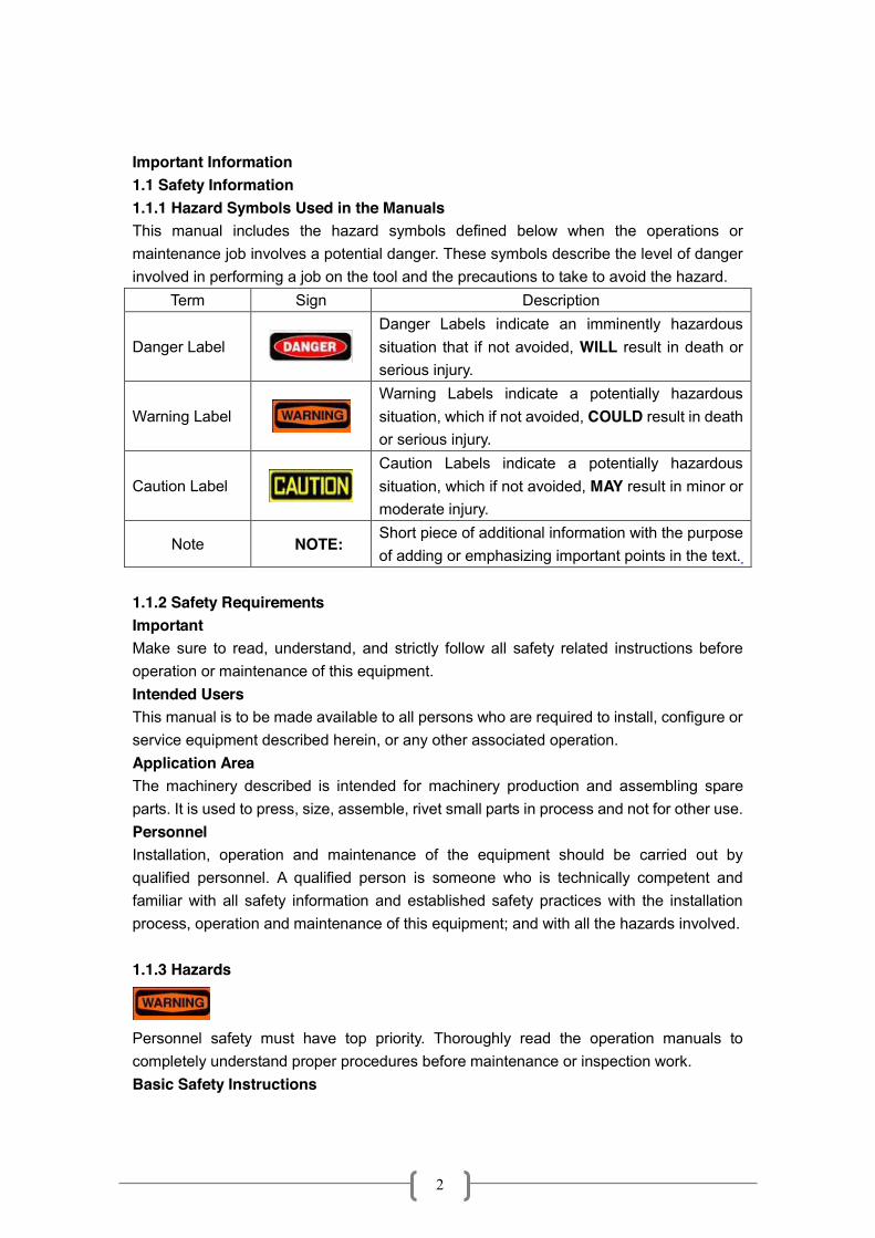
Important Information 1.1 Safety Information 1.1.1 Hazard Symbols Used in the Manuals This manual includes the hazard symbols defined below when the operations or maintenance job involves a potential danger. These symbols describe the level of danger involved in performing a job on the tool and the precautions to take to avoid the hazard.
Term Sign Description
Danger Label
Danger Labels indicate an imminently hazardous situation that if not avoided, WILL result in death or serious injury.
Warning Label
Warning Labels indicate a potentially hazardous situation, which if not avoided, COULD result in death or serious injury.
Caution Label
Caution Labels indicate a potentially hazardous situation, which if not avoided, MAY result in minor or moderate injury.
Note NOTE: Short piece of additional information with the purpose of adding or emphasizing important points in the text.
1.1.2 Safety Requirements Important Make sure to read, understand, and strictly follow all safety related instructions before operation or maintenance of this equipment. Intended Users This manual is to be made available to all persons who are required to install, configure or service equipment described herein, or any other associated operation. Application Area The machinery described is intended for machinery production and assembling spare parts. It is used to press, size, assemble, rivet small parts in process and not for other use. Personnel Installation, operation and maintenance of the equipment should be carried out by qualified personnel. A qualified person is someone who is technically competent and familiar with all safety information and established safety practices with the installation process, operation and maintenance of this equipment; and with all the hazards involved. 1.1.3 Hazards
Personnel safety must have top priority. Thoroughly read the operation manuals to completely understand proper procedures before maintenance or inspection work. Basic Safety Instructions

3
Failure to comply with the following could result in serious injury or death. 1. Periodic inspections or maintenance work must be carried out by two or more persons. 2. Read and understand the safety manual. 3. Read and understand all the attached manuals. 4. Attach visible signs on the equipment so that anyone recognizes and understands that maintenance or inspection is on going. 5. Post a list with emergency phone numbers nearby the working area. 6. Should be aware of what to do in case of an emergency (refer to the Procedures for Emergency Situations); know the location of the first-aid-kit, and the location of the fire extinguisher. Also learn how to use a fire extinguisher. 7. Alert anyone around the Tool whenever planning to operate it during maintenance or inspection work. 8. Always use proper hand tools and jigs during maintenance or inspections. Before operating the machine, check for any hand tools or jigs left inside it. For your own safety, NEVER try to remove them with the machine under operation. Consider SAFETY FIRST. 9.Please make sure that the operator must wear protective cloth, gloves, safety helmet, and shoes during operating. 10. To prevent back injury, heavy parts (or units), must be moved by two persons or more. 11. Before powering the machine, alert the persons around it. 12. Be careful not to be pinched by motion parts. 13. Use ONLY CARRIER specified for the tool, and set it in a correct position. 14. To avoid accidents, always be aware of any on-going work on the machine. Also, always stay focused on the job to be done. / 1.1.4 Safety Instruction
1. Before maintenance pressured parts in the machine, you MUST release the pressure in the pressured system. At the same time, DO NOT stand in the direction facing the charger, the operator should on the opposite side and remember DO NOT strike, press or transfer until it is discharged. 2. When it is necessary to exchange die after running, operators should wear glove or use tools to operate avoid being hurt. NOTE: Immediately stop operating the equipment if not working properly. Contact a certified technical support engineers for repair. The equipment must not be operated without approval from the certified technical support engineer.
Be careful when you are near the caution signs. Safety for material used in the machine The MSDS (Material Safety Data Sheet) information document of lubricant oils offered by supplier should be placed at the convenient place.

4
1.1.5 Prohibited Dangerous Actions
This section describes examples of dangerous actions not only during equipment operation, but also during maintenance and inspections. To avoid accidents, thoroughly read and understand the instructions below regarding dangers related to each mechanism prior to any maintenance or inspection work. 1.1.6Environmental Pollution If the substances you use come under the ordinances concerning environmental pollution, follow the ordinances to discharge and dispose of such substances. If you commission industrial waste companies, you should confirm the way of final processing.
Check for the security of people working around the Tool, before powering it back. 1.2 Warning Label Below drawing show warning labels attached on the machine.
1
Hand crush force from above
2
Read operator’s manual
3
Consult technical manual for proper service procedures
4
Must wear protective clothes
5
Must wear protective gloves

5
6
Must wear safety helmet
7
Must wear protective shoes
9
Caution, stumbling
10
Warning
11
Electrical power, danger!
12
High Temperature
13
No touching
2 Compliance with standards
European Community Directive
Manufacturer’s Assurance Harmonized Standards
2006/42/EC Machinery Directive EN60204-1:2006 Electrical Equipment of Industrial machines
6
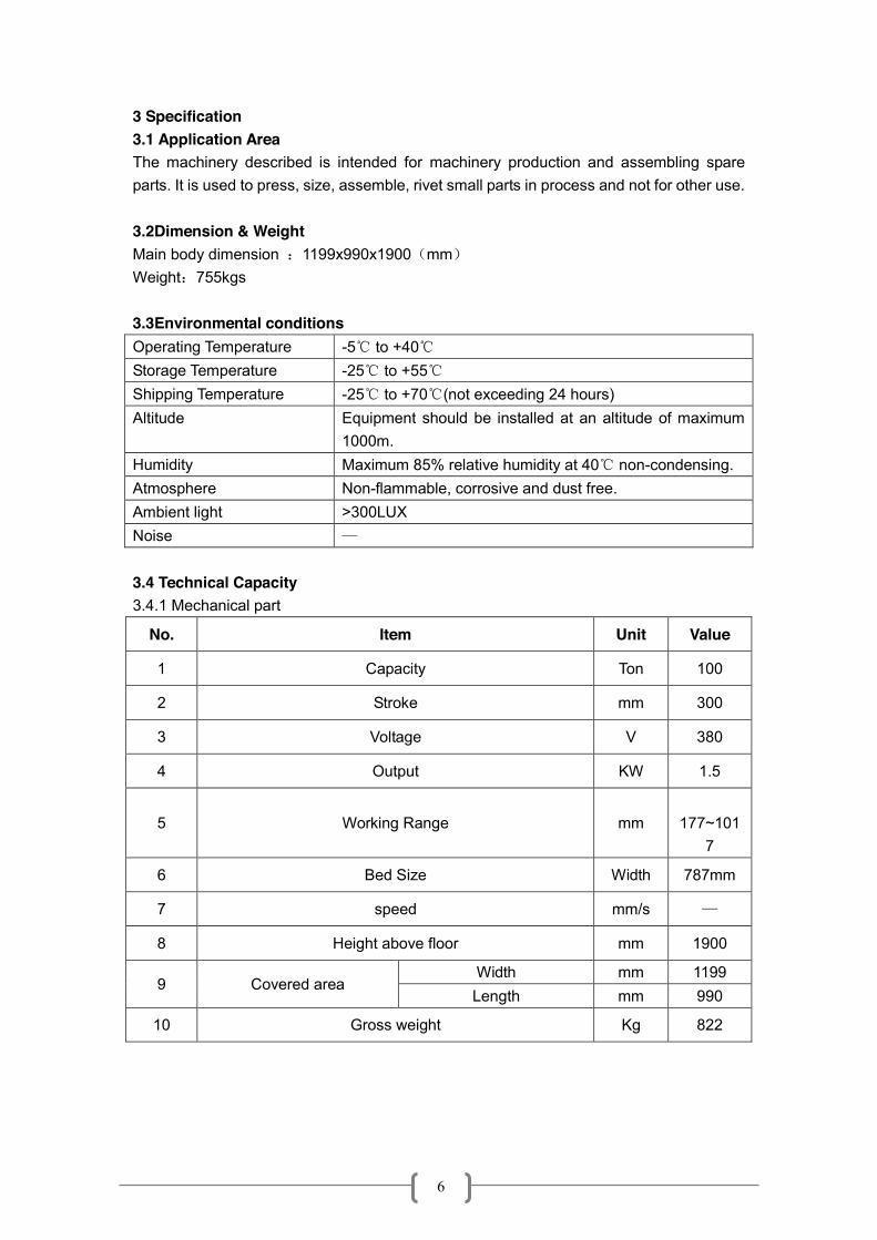
3 Specification 3.1 Application Area The machinery described is intended for machinery production and assembling spare parts. It is used to press, size, assemble, rivet small parts in process and not for other use.
3.2Dimension & Weight Main body dimension :1199x990x1900(mm) Weight:755kgs 3.3Environmental conditions Operating Temperature -5℃ to +40℃ Storage Temperature -25℃ to +55℃ Shipping Temperature -25℃ to +70℃(not exceeding 24 hours) Altitude Equipment should be installed at an altitude of maximum
1000m. Humidity Maximum 85% relative humidity at 40℃ non-condensing. Atmosphere Non-flammable, corrosive and dust free. Ambient light >300LUX Noise — 3.4 Technical Capacity 3.4.1 Mechanical part
No. Item Unit Value
1 Capacity Ton 100
2 Stroke mm 300
3 Voltage V 380
4 Output KW 1.5
5 Working Range mm
177~1017
6 Bed Size Width 787mm
7 speed mm/s —
8 Height above floor mm 1900
9 Covered area Width mm 1199 Length mm 990
10 Gross weight Kg 822

7
3.5Mechanical construction
4. Motor Instruction For Operation 4.1 Power Supply
Voltage:380V AC Frequency:50HZ Input power:3----3.5KVA output power:In 5A Ambient temperature:≤40℃ Height above sea level:≤1000M
4.2 Mounting and Operating
8
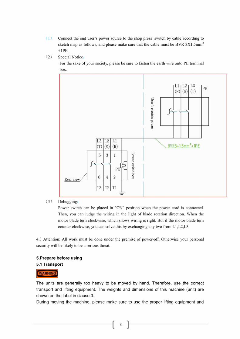
(1) Connect the end user’s power source to the shop press’ switch by cable according to
sketch map as follows, and please make sure that the cable must be BVR 3X1.5mm2
+1PE. (2) Special Notice:
For the sake of your society, please be sure to fasten the earth wire onto PE terminal box.
(3) Debugging:
Power switch can be placed in "ON" position when the power cord is connected. Then, you can judge the wiring in the light of blade rotation direction. When the motor blade turn clockwise, which shows wiring is right. But if the motor blade turn counter-clockwise, you can solve this by exchanging any two from L1,L2,L3.
4.3 Attention: All work must be done under the premise of power-off. Otherwise your personal security will be likely to be a serious threat. 5.Prepare before using 5.1 Transport
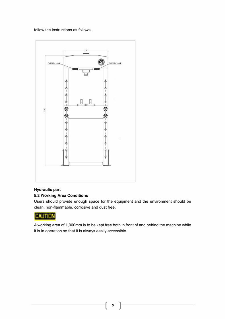
The units are generally too heavy to be moved by hand. Therefore, use the correct transport and lifting equipment. The weights and dimensions of this machine (unit) are shown on the label in clause 3. During moving the machine, please make sure to use the proper lifting equipment and
9
follow the instructions as follows.
Hydraulic part 5.2 Working Area Conditions Users should provide enough space for the equipment and the environment should be clean, non-flammable, corrosive and dust free.
A working area of 1,000mm is to be kept free both in front of and behind the machine while it is in operation so that it is always easily accessible.

10
5.3 Unpacking & Check
When open the packing, please make sure to use the proper tools, wear protective cloth, gloves, safety helmet Make sure that the product and parts in box should be complete and identical with the part list. If not, please contact with the manufacturer in time. 5.4 Disposal of the packaging The packaging of these machines consists of PVC film and carton box. The proper disposal of the packaging is the responsibility of the customer. 5.5 Installation
The machine must only be installed and commissioned by qualified personnel! All relevant safety regulations must be strictly adhered to! ¾ Electrical wire connection
Notice: 1) The voltage must be 380V, and three-phase alternating current 2) The section area of electrical wire should be no less than 2 square mm 3) The electrical wire connection should meet EN60204-1 standard 4) Before connect the electrical wire, please read the operating manual carefully 5) The electrical wire must be connected by certified technical people 6) Please connect the electrical wire according to following drawings

11
Electrical Pump Assembling Put the electrical pump on the plate of the body frame of shop press (please refer to bellowing drawing) 1) Take off the filling plug and connect the oil hose to the electrical pump as
following drawing: 2) Assemble the wire box to the shop press’ frame by bolt 3)Connect the wire to the electrical power
Before the first use, please fix the machine to the floor by anchor bole. It must be ensured that the standing surface of the machine site is firm and horizontal, and that sufficient lighting is provided for. 5.6 Commissioning the machine
Before the commissioning z Clean the machine thoroughly z Check all parts and conditions, if there is any part broken, stop using it and contact
your supplier immediately. z Open the breath valve on the oil tank and operate the machine for one minute to
exhausting the air in the system, then close the breath valve.
6 Operation z Place the heel block on press bed frame, then insert workpiece onto the heel block.。
z Turn on the switch
z Turn the operation lever to “A” position, the piston rod will come down quickly.
12
z Align workpiece and ram to ensure center-loading.
When work is done, stop pumping the handle, slowly and carefully remove load from workpiece by turning the lever to “B” position, the piston rod will go back quickly.
z Once ram has fully retracted, remove workpiece from bed frame.
7.Maintenance Maintenance should be acted before daily working everyday. Clean the outside of the press with dry, clean and soft cloth and periodically lubricate the joints and all moving parts with a light oil as needed. When not in use, store the press in a dry location with ram and piston fully retracted. Check the hydraulic oil: remove the oil filler nut on the top of the reservoir, if the oil is not adequate, fill with 22#(ISO6743) hydraulic jack oil as necessary, then replace the oil filler nut, purge away air from the hydraulic system as described in 4.2. The equipment must not be repaired or changed spare parts by whom without approval from the certified technical support engineer。
13
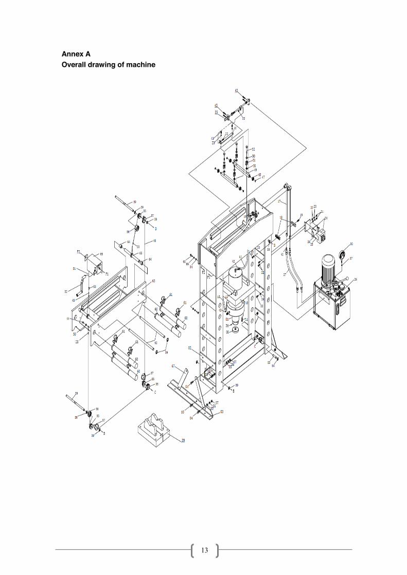
Annex A Overall drawing of machine

14
Part List Part No. Description Qty Part No. Description Qty
01 Ram Assy 1 36 Screw 1
02 Frame 1 37 Nylon Washer 1
03 Foot Base 2 38 Nut 1
04 Bolt 8 39 Circlip 12
05 Washer 12 40 Beam 1
06 Lock Washer 12 41 Bolt 2
07 Nut 12 42 O-ring 4
08 Serrated Saddle 1 43 Screw 4
09 Steel Block 1 44 Bolt 1
10 Bolt 4 45 Connector 3
11 Screw 4 46 Cable 1
12 Screw 4 47 Circlip 4
13 Ram Plate 1 48 Bearing 4
14 Oil Hose 1 49 Rod 2
15 Oil Hose 1 50 Spring Cap 9
16 Nut 2 51 Spring 4
17 Seamless tube 2 52 Bolt 4
18 Pipe Clamp 2 53 Roller Pin 1
19 Screw 1 54 Circlip 2
20 Washer 3 55 Roller 1
21 Nut 3 56 Roller Cover1 3
22 Bolt 3 57 Roller Cover2 3
23 Lock Washer 4 58 Roller 2
24 Switch Box 1 59 Roller Pin 2
25 Screw 4 60 Pin 4
26 Washer 4 61 Circlip 8
27 Short Oil Hose 2 62 Raising Rod 2
28 Cable Sheath 3 63 Working Frame 1
29 Electric Hydraulic Pump
1 64 Drivepipe 4
30 Pressure Gauge 1 65 Drivepipe Assy2 2
31 Cable 1 66 Underbeam Moving Assy
1
32 Handle 1 67 Support 4
33 Bolt 3 68 Bolt 4
34 Washer 7 69 Lock Washer 4
35 Ram Moving Assy 1 70

15
Annex B Electric Motor Pump
16
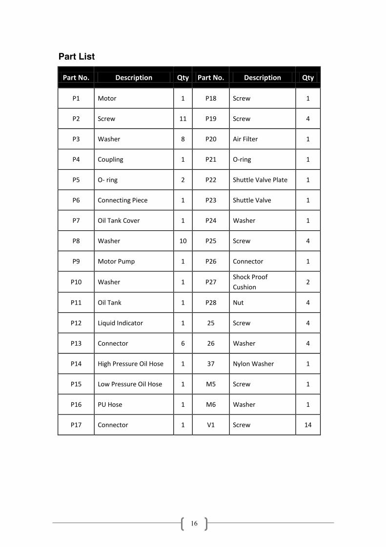
Part List
Part No. Description Qty Part No. Description Qty
P1 Motor 1 P18 Screw 1
P2 Screw 11 P19 Screw 4
P3 Washer 8 P20 Air Filter 1
P4 Coupling 1 P21 O-ring 1
P5 O- ring 2 P22 Shuttle Valve Plate 1
P6 Connecting Piece 1 P23 Shuttle Valve 1
P7 Oil Tank Cover 1 P24 Washer 1
P8 Washer 10 P25 Screw 4
P9 Motor Pump 1 P26 Connector 1
P10 Washer 1 P27 Shock Proof Cushion
2
P11 Oil Tank 1 P28 Nut 4
P12 Liquid Indicator 1 25 Screw 4
P13 Connector 6 26 Washer 4
P14 High Pressure Oil Hose 1 37 Nylon Washer 1
P15 Low Pressure Oil Hose 1 M5 Screw 1
P16 PU Hose 1 M6 Washer 1
P17 Connector 1 V1 Screw 14
17
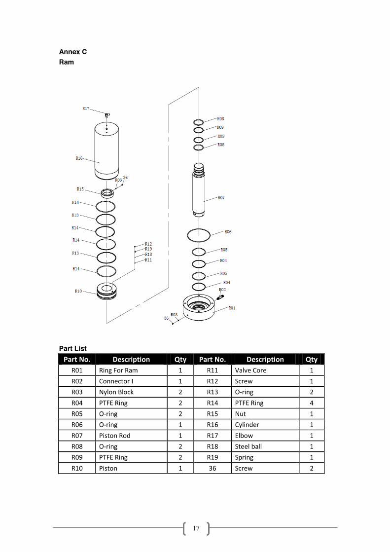
Annex C Ram
Part List
Part No. Description Qty Part No. Description Qty
R01 Ring For Ram 1 R11 Valve Core 1
R02 Connector I 1 R12 Screw 1
R03 Nylon Block 2 R13 O-ring 2
R04 PTFE Ring 2 R14 PTFE Ring 4
R05 O-ring 2 R15 Nut 1
R06 O-ring 1 R16 Cylinder 1
R07 Piston Rod 1 R17 Elbow 1
R08 O-ring 2 R18 Steel ball 1
R09 PTFE Ring 2 R19 Spring 1
R10 Piston 1 36 Screw 2


