22
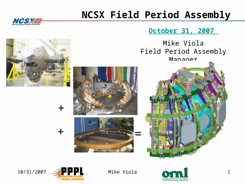
10/31/2007 Mike Viola 1 NCSX Field Period Assembly + + = October 31, 2007 Mike Viola Field Period Assembly Manager
| Date post: | 13-Dec-2015 |
| Category: |
Documents |
| Upload: | elfreda-jordan |
| View: | 215 times |
| Download: | 0 times |
10/31/2007 Mike Viola 1
NCSX Field Period Assembly
+
+ =
October 31, 2007
Mike ViolaField Period Assembly Manager

10/31/2007 Mike Viola 2
FPA is Accomplished in Four Stages
Station 1 – Vacuum Vessel (VV)
Prep
Station 2 – Modular Coil Half Period
(MCHP) Assembly
Station 3 - MCHP installation over VV Period
Station 5 - Final Assembly in NCSX Test Cell
Station 6 – Final Machine Assembly – Erik Perry

10/31/2007 Mike Viola 3
FPA Process Definitions
• FPA Manufacturing, Inspection, Test, Quality Assurance Plan (MIT/QA) Complete– Input (Station specific):
• Dimensional Control Plan (Art Brooks)• FPA Assembly Sequence Plan (Tom Brown)• FPA Specification and Assembly Drawings (Mike Cole)
– MIT/QA Plan provides basis for individual procedures to perform tasks then revised to include developed improvements.
• FPA Procedures– FPA station 1 procedure is complete and active– FPA station 2 trials are providing input to procedure
development
10/31/2007 Mike Viola 4
Design Philosophy
• We carefully assure that our designs are adequate.– Utilize outside reviewers to participate in design reviews– Complete designs early to minimize configuration changes
• not rely on concurrent engineering as much during assembly phase
• We schedule time to test the designs in advance.– Added trials to discover problems BEFORE the critical path.
• E.g. Added stud tension, bushing, and nose weld trials
– Measure all modular coils in advance of assembly• developed new alignment techniques
• We allow time to reinforce tooling or make adjustments as needed.

10/31/2007 Mike Viola 5
NCSX Vacuum Vessel Station 1 97% Complete
• VV #1 and VV #2 98% Complete• VV #3 95% Complete• Cooling tube testing and final scans
remain
VVSA with ports welded
VV #1
VV #2VV #3 complete

10/31/2007 Mike Viola 6
Station 2 Trials are Successful
• Station 2 FPA trials were enhanced and are well in progress:Gross fit individual mating coils
found a few minor interferences
• Joint design trials for Station 2 (useful for Station 3 also):Install and torque bolts – assess
accessibility SUCCESSFULDevelop shim technique
SUCCESSFULPillow shims SUCCESSFULNew welded design for inboard
interface (nose) SUCCESSFUL– Install Alumina coated metal shims
• Shims on order

10/31/2007 Mike Viola 7
Station 2 Assembly Sequence
Preparation Steps/ Major Activities
• MC Fit-up Check Verify will come together
(Gross Fit-ups)
• Pre-Measurement of MHCP Type A/B/C Coil Flanges & Interfacing Type A Coil Flange
Individual coils have been racked into proper shape. (within +/- .005”)
• Alumina Shim Sizing & Preparation
– Measure shim thicknesses to arrive at a satisfactory shim set for MCHP assembly.
Potential Issues and Mitigation Plans
• Tooling not rigid enough – RETIRED– wedges determined to be adequate
• Coils still too flexible – RETIRED– physically racked (twisted) coils to re-
establish their coordinate system• Alignment not within tolerances bars-
RETIRED– successfully met requirements
•Nose

10/31/2007 Mike Viola 8
Station 2 Assembly Sequence
A-B Modular Coil Assembly Steps/Major Activities
• Rack A coil & measure fiducials. • lower B coil into place onto outboard shims• Measure shim puck height with bore gauge• Install nose shear plates & lightly tack weld • Lift B & flip to ready for nose welding.• Establish A & B coil fiducials – weld flex shims to
plasma side both coils, recheck fiducials. Back Office assess part for compliance.
• Place B coil back on A coil and align• Install alumina shims and bushings• Weld A/B nose region solenoid side & re-measure.
REPEAT FOR C TO A-B ASSEMBLY
10/31/2007 Mike Viola 9
Station 2 Assembly Sequence
A-B Modular Coil Assembly
Potential Issues and Mitigation Plans
• Alignment not within tolerances - RETIRED– Able to achieve +/- .005” lock-in
• Weld distortion excessive– Install wing chairs to offset distortions– If required, coil welds can be ground out & coil separated

10/31/2007 Mike Viola 10
Station 2 Assembly Sequence
Final Assembly Steps/Major Activities
• Inflate All Shim Bags• Complete Local Services & Interface Details
– Install sealant to fill all shim spaces to trap VV/MC insulation.
• Final Measurements and transfer to MCHP holding area.

10/31/2007 Mike Viola 11
Station 3 Assembly Sequence
Potential Issues and Mitigation Plans
• Tooling not rigid enough– Reinforce/redesign tooling if
necessary• Left or Right MCHP changes
shape– Back Office review changes
& provides new left to right MCHP orientation
Pre-Assembly Steps/Major Activities
• Pre-Installation Set-Up – Install monuments, floor
mounted tracks & Vacuum Vessel base support, measure MCHP CG
– Anchor tooling (floor mounted tracks, support carts, adjuster bar, temporary scaffolding, etc.
• Pre-Assembly of Left MCHP – Establish global coordinate
system and install laser screens.
– Measure MCHP in vertical orientation, including A-A flange
– Perform Metrology and align
MCHP support cart assemblyMCHP
Left side
Vacuum Vessel Support
10/31/2007 Mike Viola 12
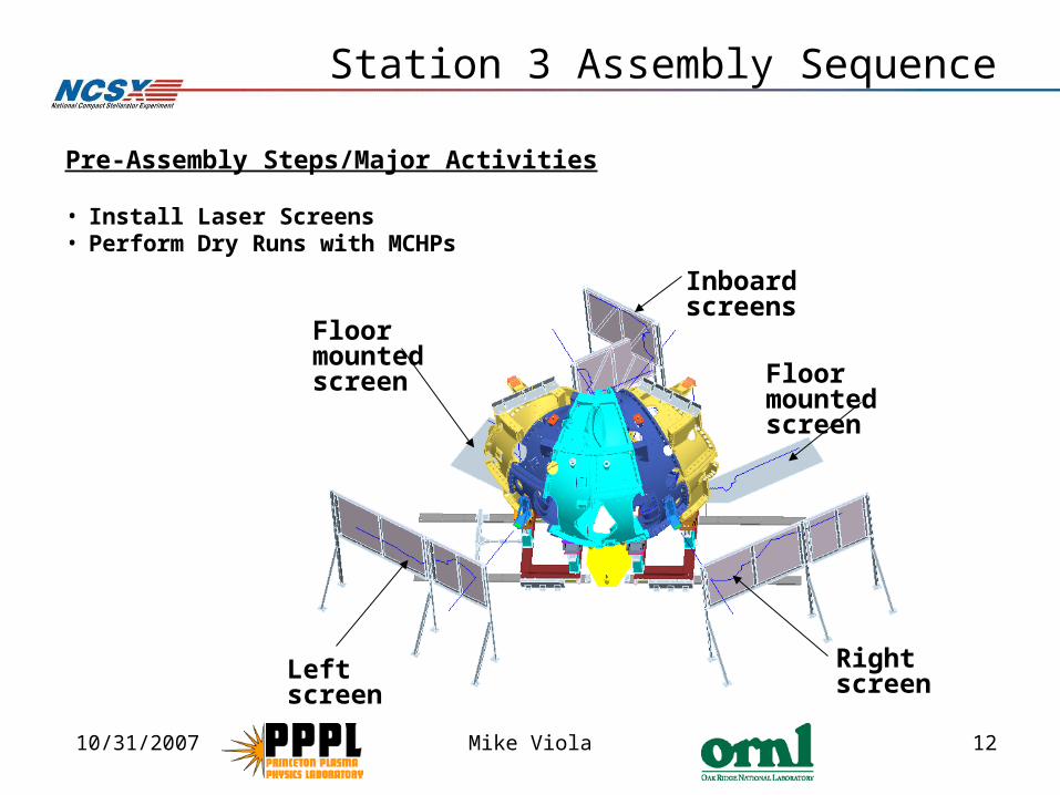
Station 3 Assembly Sequence
Pre-Assembly Steps/Major Activities
• Install Laser Screens• Perform Dry Runs with MCHPs
Inboard screens
Right screen
Floor mounted screen
Left screen
Floor mounted screen

10/31/2007 Mike Viola 13
Station 3 Assembly Sequence
Assembly Steps/Major Activities
• Install VV NBI support stand & install VVSA to base support structure.
• Using metrology, take tooling ball readings to properly position VVSA to global coordinate system.
MCHP support cart assembly
MCHP fixed support assembly
VV lateral support NBI Port
VV base support

10/31/2007 Mike Viola 14
Station 3 Assembly Sequence
Potential Issues and Mitigation Plans
• Components damaged during assembly (highly unlikely due to very slow motion).– remove MCHP from vessel & repair
damaged component with existing spare component e.g. cooling tube or clamp.
• Weld distortion excessive– Install wing chairs to offset
distortions– If required, coil welds can be ground
out & coil separated
Assembly Steps/Major Activities
• Install Left then Right MCHP over VVSA
• Weld Inboard Shims and re-measure alignment
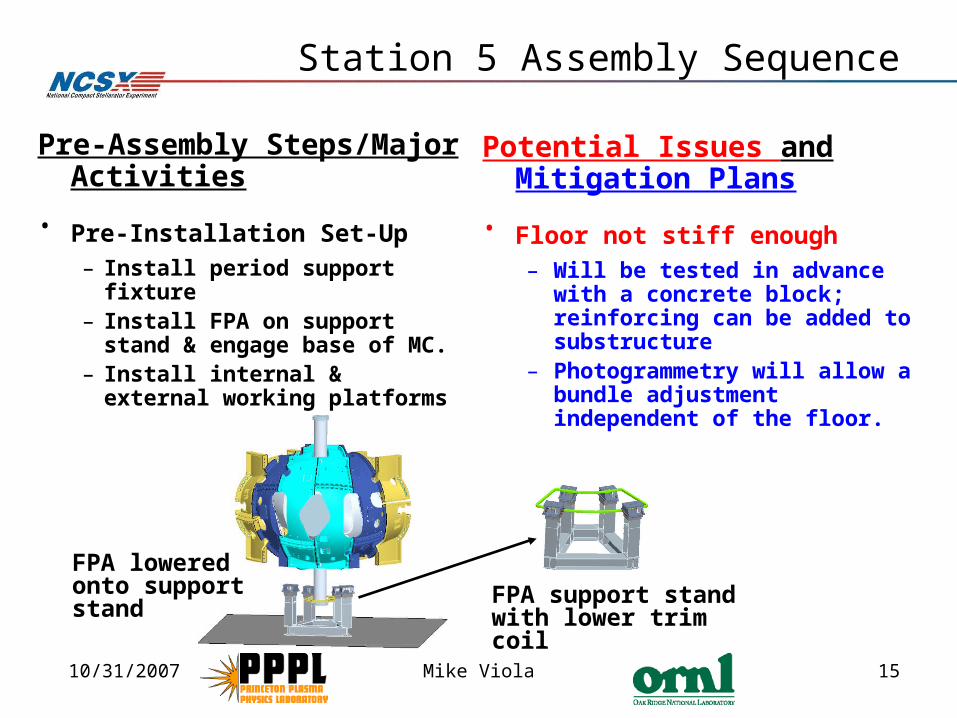
10/31/2007 Mike Viola 15
Station 5 Assembly Sequence
Potential Issues and Mitigation Plans
• Floor not stiff enough – Will be tested in advance with a
concrete block; reinforcing can be added to substructure
– Photogrammetry will allow a bundle adjustment independent of the floor.
Pre-Assembly Steps/Major Activities
• Pre-Installation Set-Up – Install period support fixture– Install FPA on support stand
& engage base of MC. – Install internal & external
working platforms
FPA lowered onto support stand
FPA support stand with lower trim coil

10/31/2007 Mike Viola 16
Station 5 Assembly Sequence
Potential Issues and Mitigation Plans
• Difficulty of welders working inside VV in contorted positions may pose ergonomic & confined space hazards– Ergonomic / confined space
hazards – prior Job Hazard Analysis (JHA) will consider all hazards
• Leak check fails on one or more ports– Identify leak point (s), repair weld
and re-test
Assembly Steps/Major Activities
• VV Port Installation – Install circular ports. – Install domes, inserting the
long port through the MC hole opening & weld dome shell to VV.
– Leak check all port welds.
1” – 2” clearance around all ports

10/31/2007 Mike Viola 17
Station 5 Assembly Sequence
Assembly Steps/Major Activities
• Trim Coil Installation
– Install trim coils - mounted to the MC shells using local field fit support brackets
There are four different trim coil sizes.
10/31/2007 Mike Viola 18
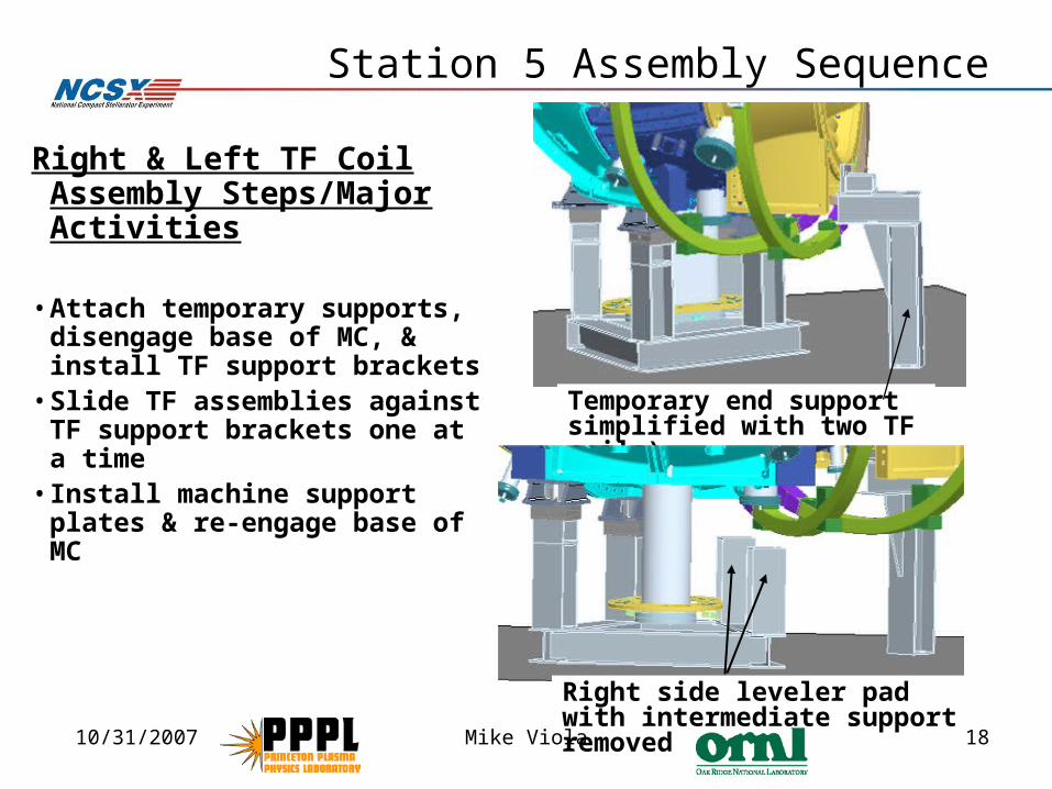
Station 5 Assembly Sequence
Right & Left TF Coil Assembly Steps/Major Activities
• Attach temporary supports, disengage base of MC, & install TF support brackets
• Slide TF assemblies against TF support brackets one at a time
• Install machine support plates & re-engage base of MC
Temporary end support simplified with two TF coils)
Right side leveler pad with intermediate support removed

10/31/2007 Mike Viola 19
Station 5 Assembly Sequence
Assembly Steps/Major Activities
•Advanced TF Fit-Up Checks
Install TF support brackets on the sides of the coils, both on the top of the MC and on the bottom.
10/31/2007 Mike Viola 20
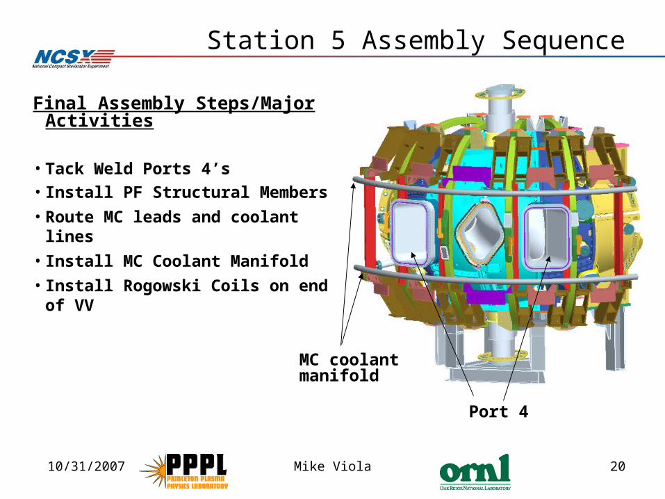
Station 5 Assembly Sequence
Final Assembly Steps/Major Activities
• Tack Weld Ports 4’s
• Install PF Structural Members
• Route MC leads and coolant lines
• Install MC Coolant Manifold
• Install Rogowski Coils on end of VV
Port 4
MC coolant manifold
10/31/2007 Mike Viola 21
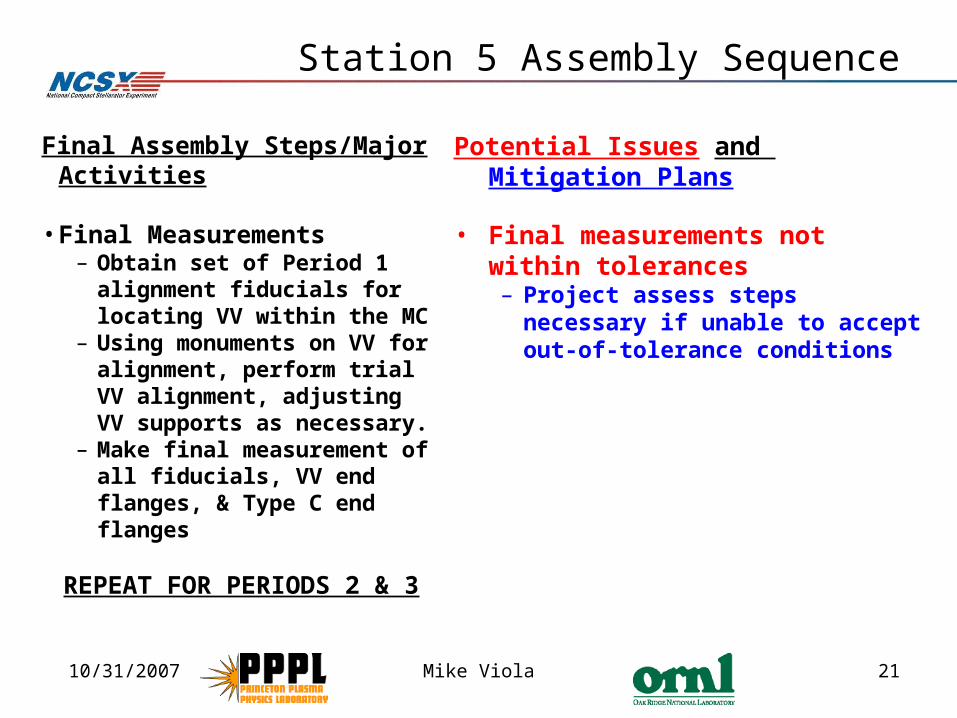
Station 5 Assembly Sequence
Potential Issues and Mitigation Plans
• Final measurements not within tolerances – Project assess steps necessary if
unable to accept out-of-tolerance conditions
Final Assembly Steps/Major Activities
• Final Measurements– Obtain set of Period 1
alignment fiducials for locating VV within the MC
– Using monuments on VV for alignment, perform trial VV alignment, adjusting VV supports as necessary.
– Make final measurement of all fiducials, VV end flanges, & Type C end flanges
REPEAT FOR PERIODS 2 & 3

10/31/2007 Mike Viola 22
Summary
• Station 1 vacuum vessel segments are nearly complete. • Station 2 modular coil assembly trials are well underway,
most risks are retired, and assembly steps are well defined.
• Station 3 installing the modular coil half period assembly over the vacuum vessel and Station 5 final field period assembly sequence plans have been developed in detail and include the necessary metrology and trial elements.
• We have a credible plan to assemble the field periods to the accuracy required.
• I have confidence in successfully performing the Field Period Assembly activities.


