312 NEL Unit D Optics The effects of reflection and refraction are used to design a variety of optical devices. Mirrors and lenses change our view of the world. In the photograph, you can see a soccer ball as it would normally appear to your eyes, and as its reflection would appear in different mirrors. What happens when light hits a mirror? How do mirrors work? In this chapter, you will investigate the behaviour of light as it reflects off or passes through different materials. Understanding how light behaves has led to the development of technologies that allow us to see better and farther, and to see objects that are too small to be seen with the unaided eye. Mirrors and Lenses Light reflects off surfaces in a predictable way. Optical devices produce images that can have different characteristics. Mirrors produce images by reflecting light. When light passes through a transparent material, it may change direction. Lenses produce images by refracting light. KEY IDEAS 11 CHAPTER LEARNING TIP Read the Key Ideas. This will you give you the specific information that you need to pay attention to as you read the chapter. As you read the Key Ideas, ask yourself, “What do I already know about this topic?”
Transcript
312 NELUnit D Optics
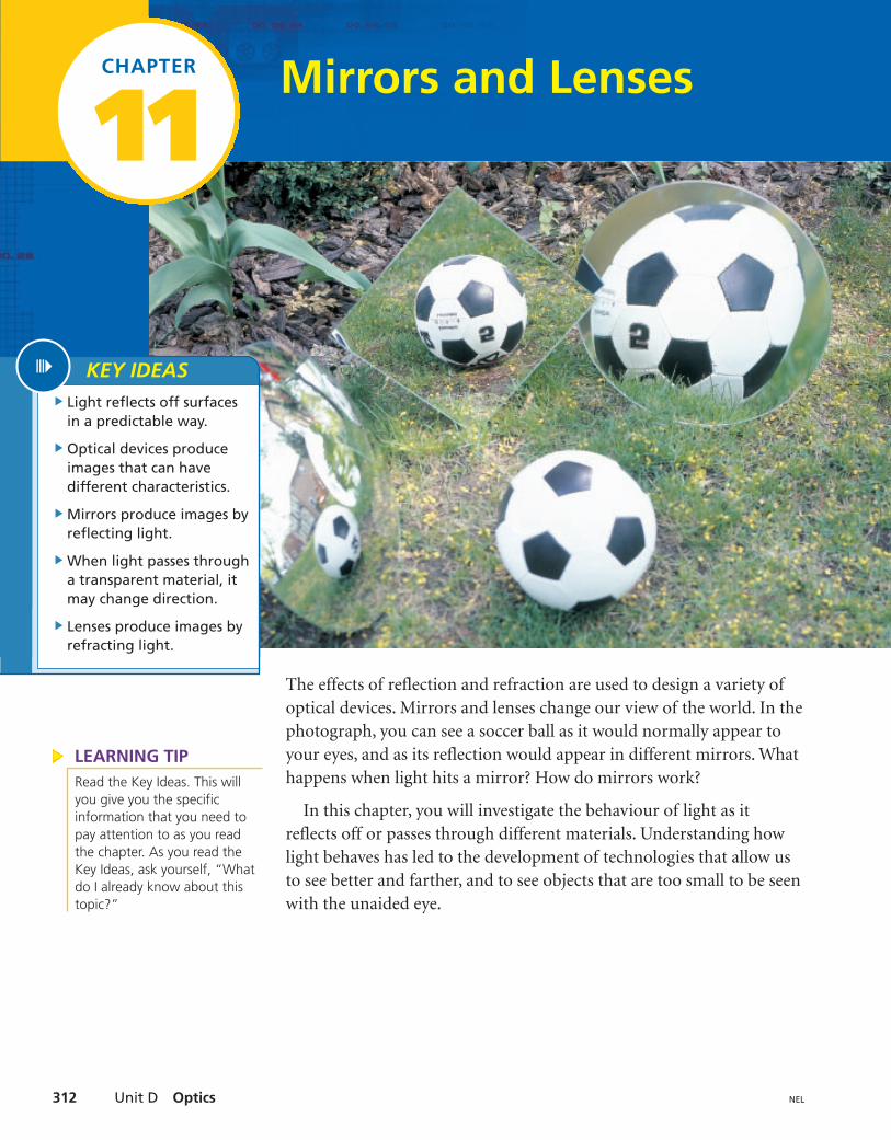
The effects of reflection and refraction are used to design a variety ofoptical devices. Mirrors and lenses change our view of the world. In thephotograph, you can see a soccer ball as it would normally appear toyour eyes, and as its reflection would appear in different mirrors. Whathappens when light hits a mirror? How do mirrors work?
In this chapter, you will investigate the behaviour of light as itreflects off or passes through different materials. Understanding howlight behaves has led to the development of technologies that allow usto see better and farther, and to see objects that are too small to be seenwith the unaided eye.
Mirrors and Lenses
Light reflects off surfacesin a predictable way.
Optical devices produceimages that can havedifferent characteristics.
Mirrors produce images byreflecting light.
When light passes througha transparent material, itmay change direction.
Lenses produce images byrefracting light.
KEY IDEAS
11CHAPTER
LEARNING TIPRead the Key Ideas. This willyou give you the specificinformation that you need topay attention to as you readthe chapter. As you read theKey Ideas, ask yourself, “Whatdo I already know about thistopic?”
11.1 Inquiry Investigation 313NEL
Reflecting Light off a Plane MirrorMirrors—dentists use them to examine your teeth, drivers use them tomonitor traffic, decorators use them to make rooms seem larger, andyou use them to check that you don’t have the remains of your lunch onyour nose. Regular, flat mirrors are called (Here, theword plane means “a flat, two-dimensional surface,” just as it does inmathematics.) In this Investigation, you will study how light reflects offa plane mirror.
You will use a protractor to measure angles in this Investigation.Whenever you measure an angle, always estimate its value first. Then,you can check that the result of your measurement makes sense.
Question(a) Write a question that will be answered in this Investigation.
Prediction(b) Look at Figure 1. Make a prediction about the relationship
between the angle of incidence and the angle of reflection.
plane mirrors.
INQUIRY SKILLS
Questioning Hypothesizing
Predicting Planning
Conducting Recording
Analyzing Evaluating
Communicating
Inquiry Investigation 11.1
reflecting surface
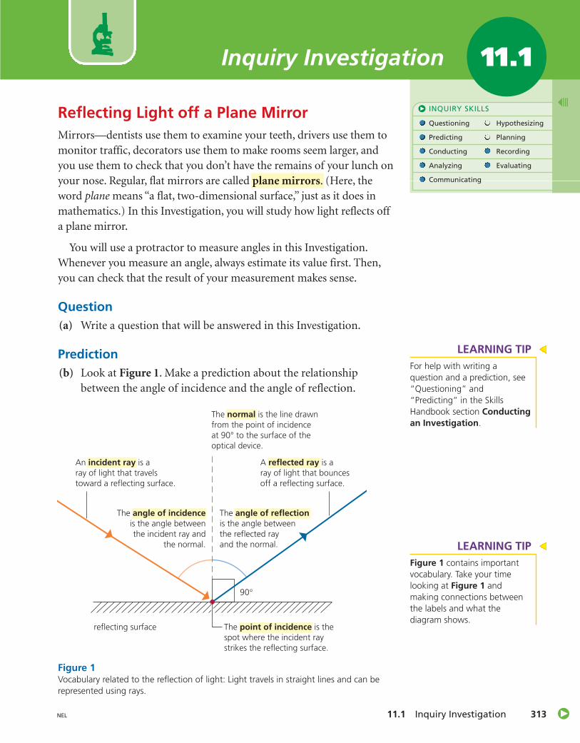
An incident ray is aray of light that travelstoward a reflecting surface.
The point of incidence is thespot where the incident raystrikes the reflecting surface.
The angle of incidenceis the angle betweenthe incident ray and
the normal.
The angle of reflectionis the angle betweenthe reflected rayand the normal.
A reflected ray is aray of light that bouncesoff a reflecting surface.
The normal is the line drawnfrom the point of incidenceat 90° to the surface of theoptical device.
Figure 1Vocabulary related to the reflection of light: Light travels in straight lines and can berepresented using rays.
LEARNING TIPFor help with writing aquestion and a prediction, see“Questioning” and“Predicting” in the SkillsHandbook section Conductingan Investigation.
LEARNING TIPFigure 1 contains importantvocabulary. Take your timelooking at Figure 1 andmaking connections betweenthe labels and what thediagram shows.
Unit D Optics314 NEL
Experimental DesignYou will trace the path of a ray from a ray box as the ray reflects off aplane mirror.Do not touch the
light bulb in the raybox or look directlyinto the light. Handlemirrors carefully toavoid breakage.
Materials• ray box with single-slit window• plane mirror that can stand by
itself• ruler
• sharp pencil• plain paper• protractor
Procedure
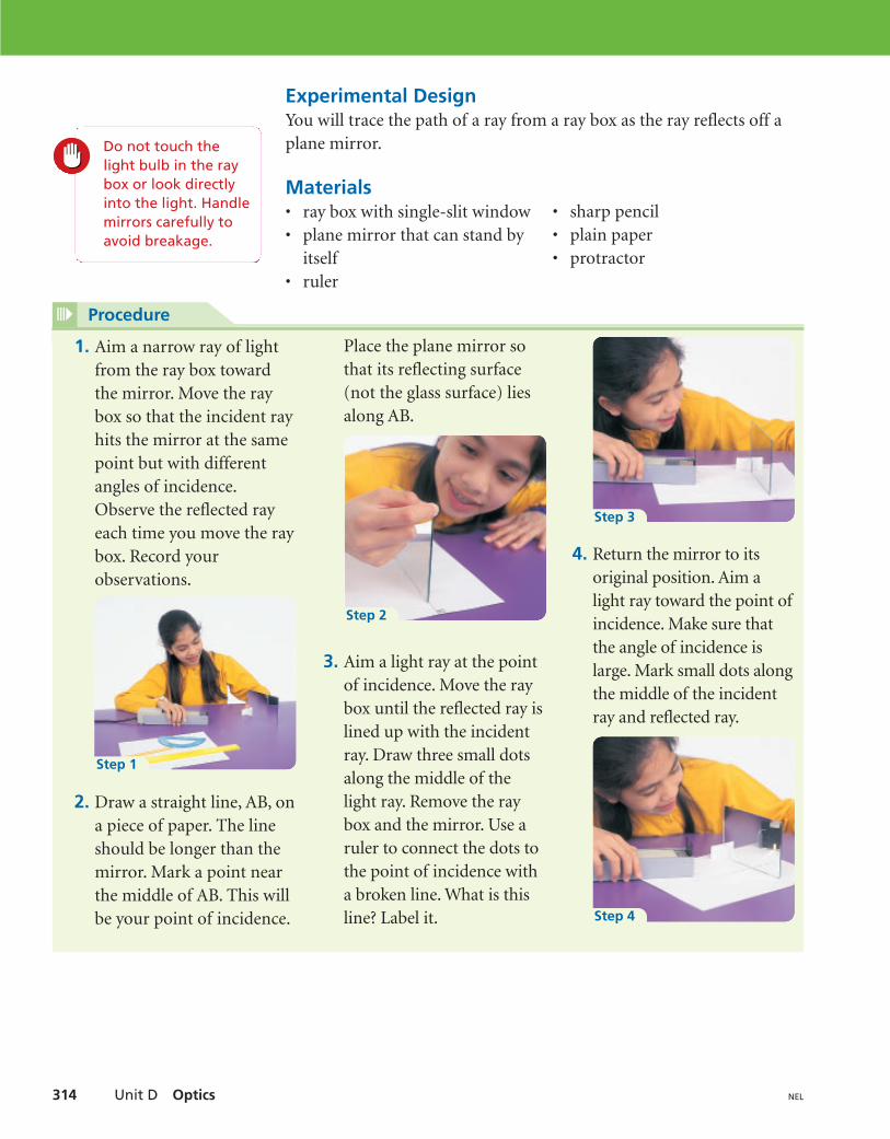
1. Aim a narrow ray of lightfrom the ray box towardthe mirror. Move the raybox so that the incident rayhits the mirror at the samepoint but with differentangles of incidence.Observe the reflected rayeach time you move the raybox. Record yourobservations.
2. Draw a straight line, AB, ona piece of paper. The lineshould be longer than themirror. Mark a point nearthe middle of AB. This willbe your point of incidence.
Place the plane mirror sothat its reflecting surface(not the glass surface) liesalong AB.
3. Aim a light ray at the pointof incidence. Move the raybox until the reflected ray islined up with the incidentray. Draw three small dotsalong the middle of thelight ray. Remove the raybox and the mirror. Use aruler to connect the dots tothe point of incidence witha broken line. What is thisline? Label it.
4. Return the mirror to itsoriginal position. Aim alight ray toward the point ofincidence. Make sure thatthe angle of incidence islarge. Mark small dots alongthe middle of the incidentray and reflected ray.
Step 1
Step 2
Step 4
Step 3
11.1 Inquiry Investigation 315NEL
Analysis(c) Summarize your results in a table.
(d) Where is the reflected ray when the incident ray travels along thenormal to a plane mirror?
(e) What are the angles of incidence and reflection in thisInvestigation?
(f) Scientists use two laws to describe how light reflects from a planemirror. The first law of reflection compares the angle of incidencewith the angle of reflection for light rays hitting a mirror. Basedon your observations, write your version of the first law ofreflection.
Evaluation(g) Did your evidence support your prediction? Explain.
(h) Did your observations provide evidence that allowed you toanswer the question you wrote at the beginning of thisInvestigation? If so, write the answer. If not, revise the question.
(i) Where might errors occur in this Investigation? How would theseerrors affect your conclusion?
(j) When conducting this Investigation, did you and your partnershare the recording and physical work equally? How might youwork differently with a partner or a group in upcomingInvestigations?
Procedure (continued)
5. Remove the mirror and theray box. Use a ruler to jointhe dots for each ray to thepoint of incidence. Labelthe rays, and show theirdirections with arrows. Use
your protractor to measurethe angle of incidence andthe angle of reflection inyour diagram. Record thesizes of the angles in yourdiagram.
6. Repeat steps 4 and 5 on anew piece of paper forseveral different angles ofincidence.
Knowing the laws of reflectionmeans that mathematics can beused in the design of opticaldevices. Are there features of yourchosen optical device that can bedescribed mathematically?
PERFORMANCE TASK
Unit D Optics316 NEL
Reflecting Light off Surfaces11.2
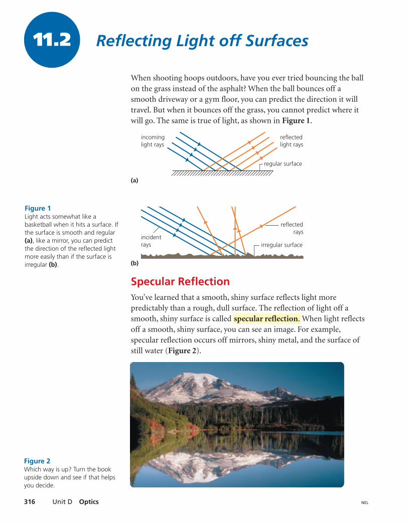
When shooting hoops outdoors, have you ever tried bouncing the ballon the grass instead of the asphalt? When the ball bounces off asmooth driveway or a gym floor, you can predict the direction it willtravel. But when it bounces off the grass, you cannot predict where itwill go. The same is true of light, as shown in Figure 1.
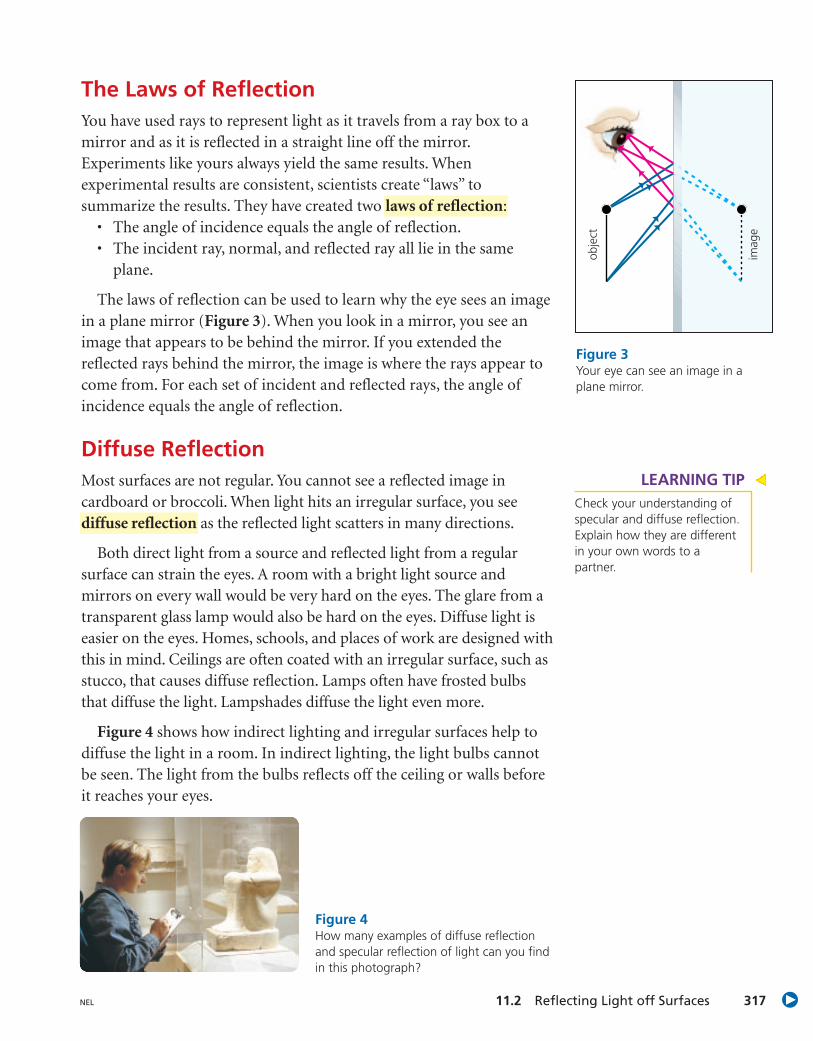
Specular ReflectionYou’ve learned that a smooth, shiny surface reflects light morepredictably than a rough, dull surface. The reflection of light off asmooth, shiny surface is called When light reflectsoff a smooth, shiny surface, you can see an image. For example,specular reflection occurs off mirrors, shiny metal, and the surface ofstill water (Figure 2).
specular reflection.
(a)
(b)
incominglight rays
reflectedlight rays
regular surface
reflectedrays
irregular surface incidentrays
Figure 1Light acts somewhat like abasketball when it hits a surface. Ifthe surface is smooth and regular(a), like a mirror, you can predictthe direction of the reflected lightmore easily than if the surface isirregular (b).
Figure 2Which way is up? Turn the bookupside down and see if that helpsyou decide.
11.2 Reflecting Light off Surfaces 317NEL
The Laws of ReflectionYou have used rays to represent light as it travels from a ray box to amirror and as it is reflected in a straight line off the mirror.Experiments like yours always yield the same results. Whenexperimental results are consistent, scientists create “laws” tosummarize the results. They have created two laws of reflection:
• The angle of incidence equals the angle of reflection.• The incident ray, normal, and reflected ray all lie in the same
plane.
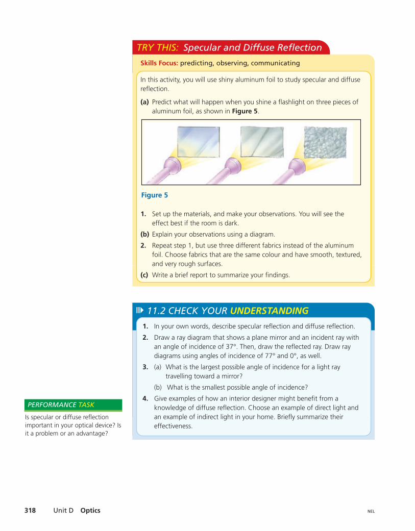
The laws of reflection can be used to learn why the eye sees an imagein a plane mirror (Figure 3). When you look in a mirror, you see animage that appears to be behind the mirror. If you extended thereflected rays behind the mirror, the image is where the rays appear tocome from. For each set of incident and reflected rays, the angle ofincidence equals the angle of reflection.
Diffuse ReflectionMost surfaces are not regular. You cannot see a reflected image incardboard or broccoli. When light hits an irregular surface, you seediffuse reflection as the reflected light scatters in many directions.
Both direct light from a source and reflected light from a regularsurface can strain the eyes. A room with a bright light source andmirrors on every wall would be very hard on the eyes. The glare from atransparent glass lamp would also be hard on the eyes. Diffuse light iseasier on the eyes. Homes, schools, and places of work are designed withthis in mind. Ceilings are often coated with an irregular surface, such asstucco, that causes diffuse reflection. Lamps often have frosted bulbsthat diffuse the light. Lampshades diffuse the light even more.
Figure 4 shows how indirect lighting and irregular surfaces help todiffuse the light in a room. In indirect lighting, the light bulbs cannotbe seen. The light from the bulbs reflects off the ceiling or walls beforeit reaches your eyes.
imag
e
obje
ct
Figure 3Your eye can see an image in aplane mirror.
Figure 4How many examples of diffuse reflectionand specular reflection of light can you findin this photograph?
LEARNING TIPCheck your understanding ofspecular and diffuse reflection.Explain how they are differentin your own words to apartner.
Unit D Optics318 NEL
TRY THIS: Specular and Diffuse Reflection
In this activity, you will use shiny aluminum foil to study specular and diffusereflection.
(a) Predict what will happen when you shine a flashlight on three pieces ofaluminum foil, as shown in Figure 5.
1. Set up the materials, and make your observations. You will see theeffect best if the room is dark.
(b) Explain your observations using a diagram.
2. Repeat step 1, but use three different fabrics instead of the aluminumfoil. Choose fabrics that are the same colour and have smooth, textured,and very rough surfaces.
(c) Write a brief report to summarize your findings.
1. In your own words, describe specular reflection and diffuse reflection.
2. Draw a ray diagram that shows a plane mirror and an incident ray withan angle of incidence of 37°. Then, draw the reflected ray. Draw raydiagrams using angles of incidence of 77° and 0°, as well.
3. (a) What is the largest possible angle of incidence for a light raytravelling toward a mirror?
(b) What is the smallest possible angle of incidence?
4. Give examples of how an interior designer might benefit from aknowledge of diffuse reflection. Choose an example of direct light andan example of indirect light in your home. Briefly summarize theireffectiveness.
11.2 CHECK YOUR UNDERSTANDING
Is specular or diffuse reflectionimportant in your optical device? Isit a problem or an advantage?
PERFORMANCE TASK
11.3 Describing Images 319NEL
Describing Images
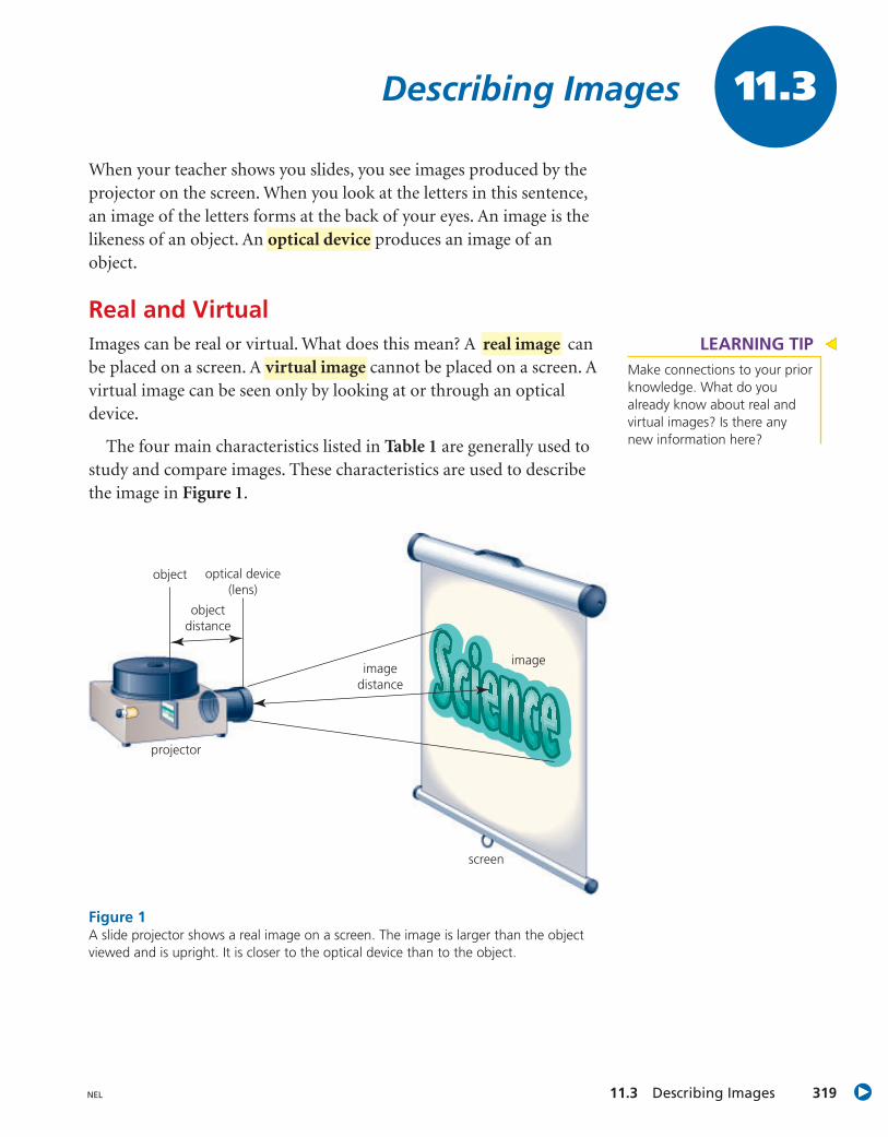
When your teacher shows you slides, you see images produced by theprojector on the screen. When you look at the letters in this sentence,an image of the letters forms at the back of your eyes. An image is thelikeness of an object. An produces an image of anobject.
Real and VirtualImages can be real or virtual. What does this mean? A canbe placed on a screen. A virtual image cannot be placed on a screen. Avirtual image can be seen only by looking at or through an opticaldevice.
The four main characteristics listed in Table 1 are generally used tostudy and compare images. These characteristics are used to describethe image in Figure 1.
real image
optical device
11.3
object optical device(lens)
objectdistance
imagedistance
image
screen
projector
Figure 1A slide projector shows a real image on a screen. The image is larger than the objectviewed and is upright. It is closer to the optical device than to the object.
LEARNING TIPMake connections to your priorknowledge. What do youalready know about real andvirtual images? Is there anynew information here?
Unit D Optics320 NEL
Table 1 Characteristics of Images
Characteristic Possible descriptions
size • smaller than the object viewed
• larger than the object viewed
• same size as the object viewed
attitude • upright (right-side up)
• inverted (upside down)
location • several choices
• examples: on the side of the lens opposite the object;closer to the optical device than to the object
type • real image (can be placed on a screen)
• virtual image (can be seen only by looking at orthrough an optical device)
TRY THIS: Images in a Pinhole Camera
You can use a homemade pinhole camera to investigate images. A pinholecamera is a box with a tiny hole at one end and a viewing screen at theother end. It can be as small as a shoebox or as large as a box for packing anew refrigerator. You can even stand inside a large pinhole camera to viewthe images! Figure 2 shows how to make a small pinhole camera.
1. Aim the pinhole toward the object you want to see and look at thescreen.
(a) What are the characteristics of the image of an object that is a fewmetres away from the camera?
(b) What happens to the image as the camera gets closer to the object?
(c) What happens if a second pinhole is made about 1 cm below the firstpinhole?
(d) Draw a diagram to show how an image is formed in a pinhole camera.
(e) Is the image that is seen in a pinhole camera real or virtual? Why?
Skills Focus: creating models, observing
Do not look at theSun or any otherbright source of lightwith a pinhole camera. The lightcould damage youreyes.
camera
translucent viewingscreen (taped onpermanently)
opaque paper (replacedfor each experiment)
Figure 2This type of pinhole camera is easyto make. Aim the pinhole towardthe object you want to see, andlook at the screen. 1. Describe the characteristics of the image you see when your teacher
uses an overhead projector.
2. The screen in a pinhole camera must be translucent rather thantransparent or opaque. Why?
11.3 CHECK YOUR UNDERSTANDING
LEARNING TIPRefer to Table 1 when youcomplete the Try This activityon this page.
11.4 Inquiry Investigation 321NEL
Viewing Images in a Plane MirrorEveryone uses mirrors. When you look in a plane mirror, you see animage of the object, not the object itself. As you learned inSection 11.3, an image can be described using four characteristics: size,attitude, location, and type.
QuestionWhat are the characteristics of an image seen in a plane mirror?
Prediction(a) Predict what you will discover in this Investigation.
Hypothesis(b) From your experience with mirrors, write a hypothesis that
explains the image seen in a plane mirror.
Experimental DesignYou will view images in mirrors and draw diagrams to help youdescribe these images.
Materials• safety goggles• large plane mirror• plain paper• flat cardboard• ruler• small plane mirror (or MIRA)• four pins
INQUIRY SKILLS
Questioning Hypothesizing
Predicting Planning
Conducting Recording
Analyzing Evaluating
Communicating
Inquiry Investigation 11.4
Handle mirrors carefully to avoidbreakage.To avoid injury, handle pins withcare.
LEARNING TIPFor help with writing aprediction and a hypothesis,see “Predicting” and“Hypothesizing” in the SkillsHandbook section Conductingan Investigation.
Unit D Optics322 NEL
Analysis(b) State the four characteristics of the image in this Investigation.
(c) In step 5, how did the distance from the image to the mirrorcompare with the distance from the object to the mirror?
Evaluation(d) Did your observations support your prediction? Explain.
(e) Describe any possible sources of error in this Investigation.
Procedure
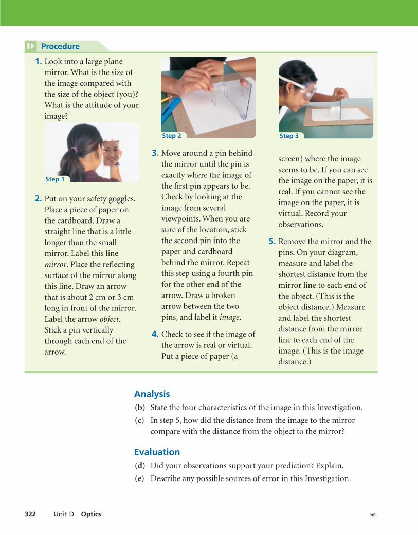
1. Look into a large planemirror. What is the size ofthe image compared withthe size of the object (you)?What is the attitude of yourimage?
2. Put on your safety goggles.Place a piece of paper onthe cardboard. Draw astraight line that is a littlelonger than the smallmirror. Label this linemirror. Place the reflectingsurface of the mirror alongthis line. Draw an arrowthat is about 2 cm or 3 cmlong in front of the mirror.Label the arrow object.Stick a pin verticallythrough each end of thearrow.
3. Move around a pin behindthe mirror until the pin isexactly where the image ofthe first pin appears to be.Check by looking at theimage from severalviewpoints. When you aresure of the location, stickthe second pin into thepaper and cardboardbehind the mirror. Repeatthis step using a fourth pinfor the other end of thearrow. Draw a brokenarrow between the twopins, and label it image.
4. Check to see if the image ofthe arrow is real or virtual.Put a piece of paper (a
screen) where the imageseems to be. If you can seethe image on the paper, it isreal. If you cannot see theimage on the paper, it isvirtual. Record yourobservations.
5. Remove the mirror and thepins. On your diagram,measure and label theshortest distance from themirror line to each end ofthe object. (This is theobject distance.) Measureand label the shortestdistance from the mirrorline to each end of theimage. (This is the imagedistance.)
Step 1
Step 2 Step 3
11.5 Inquiry Investigation 323NEL
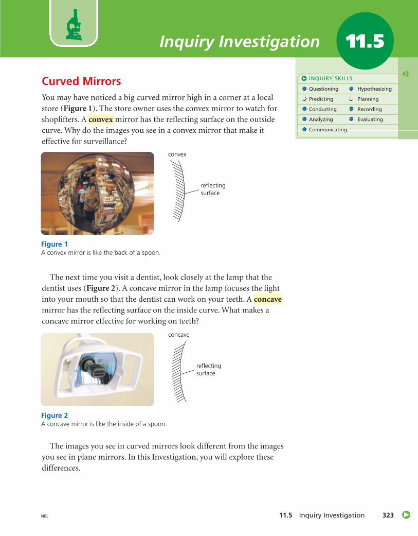
Curved MirrorsYou may have noticed a big curved mirror high in a corner at a localstore (Figure 1). The store owner uses the convex mirror to watch forshoplifters. A mirror has the reflecting surface on the outsidecurve. Why do the images you see in a convex mirror that make iteffective for surveillance?
The next time you visit a dentist, look closely at the lamp that thedentist uses (Figure 2). A concave mirror in the lamp focuses the lightinto your mouth so that the dentist can work on your teeth. Amirror has the reflecting surface on the inside curve. What makes aconcave mirror effective for working on teeth?
The images you see in curved mirrors look different from the imagesyou see in plane mirrors. In this Investigation, you will explore thesedifferences.
concave
convex
INQUIRY SKILLS
Questioning Hypothesizing
Predicting Planning
Conducting Recording
Analyzing Evaluating
Communicating
Inquiry Investigation 11.5
Figure 1A convex mirror is like the back of a spoon.
convex
reflectingsurface
reflectingsurface
concave
Figure 2A concave mirror is like the inside of a spoon.
Unit D Optics324 NEL
Question(a) What question is being investigated?
Hypothesis(b) Create a hypothesis for this Investigation.
Experimental DesignYou will use a ray box to investigate the properties of curved mirrors.
Procedure
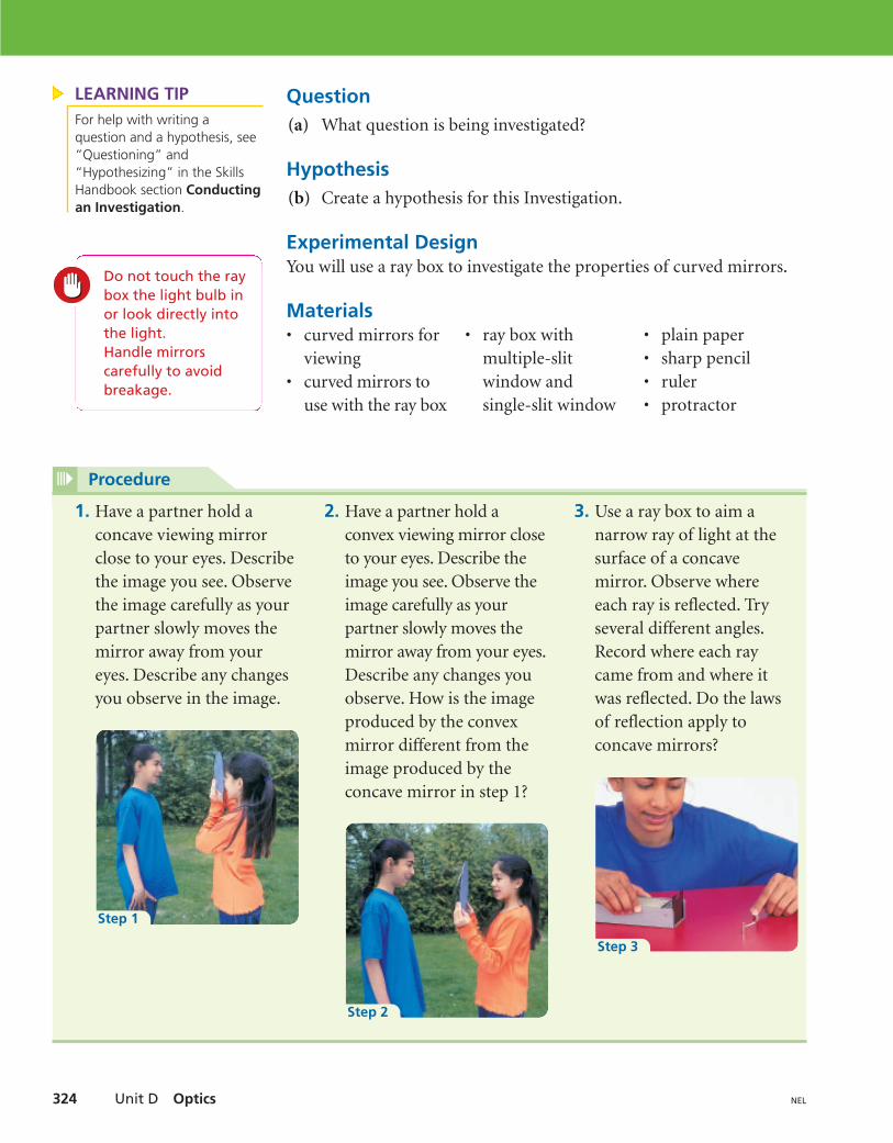
1. Have a partner hold aconcave viewing mirrorclose to your eyes. Describethe image you see. Observethe image carefully as yourpartner slowly moves themirror away from youreyes. Describe any changesyou observe in the image.
2. Have a partner hold aconvex viewing mirror closeto your eyes. Describe theimage you see. Observe theimage carefully as yourpartner slowly moves themirror away from your eyes.Describe any changes youobserve. How is the imageproduced by the convexmirror different from theimage produced by theconcave mirror in step 1?
3. Use a ray box to aim anarrow ray of light at thesurface of a concavemirror. Observe whereeach ray is reflected. Tryseveral different angles.Record where each raycame from and where itwas reflected. Do the lawsof reflection apply toconcave mirrors?
Step 1
Step 2
Step 3
Materials• curved mirrors for
viewing• curved mirrors to
use with the ray box
• ray box withmultiple-slitwindow andsingle-slit window
• plain paper• sharp pencil• ruler• protractor
Do not touch the raybox the light bulb inor look directly intothe light.Handle mirrors carefully to avoidbreakage.
LEARNING TIPFor help with writing aquestion and a hypothesis, see“Questioning” and“Hypothesizing” in the SkillsHandbook section Conductingan Investigation.
11.5 Inquiry Investigation 325NEL
Analysis(c) Use your observations and the characteristics of images to
describe the images seen in each mirror. Is each image real orvirtual?
(i) a concave mirror when the object is close to the mirror
(ii) a concave mirror when the object is far away from the mirror
(iii) a convex mirror when the object is close to the mirror
(iv) a convex mirror when the object is far away from the mirror
(d) In part (c), you had to decide whether the image in each mirror wasreal or virtual. What evidence did you use to support your decision?Describe how you could demonstrate whether or not each mirrorproduced a real image. Draw a diagram of the set-up.
Evaluation(e) Did your observations enable you to answer your question at the
beginning of this Investigation? Why or why not?
(f) Did your observations support your hypothesis? Explain.
Concave mirrors can be used tofocus light. Are concave mirrorsused in your optical device? Areconvex mirrors used?
PERFORMANCE TASK
Procedure (continued)
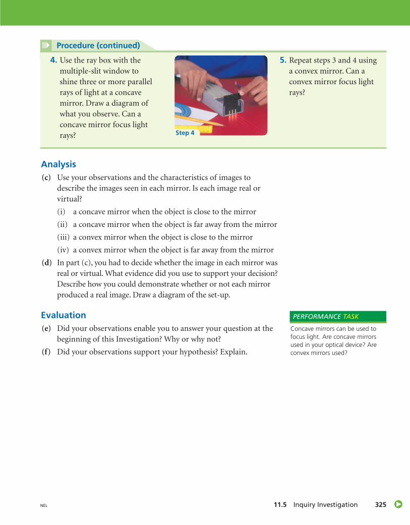
4. Use the ray box with themultiple-slit window toshine three or more parallelrays of light at a concavemirror. Draw a diagram ofwhat you observe. Can aconcave mirror focus lightrays?
5. Repeat steps 3 and 4 usinga convex mirror. Can aconvex mirror focus lightrays?
Step 4
Unit D Optics326 NEL
Using Curved Mirrors11.6
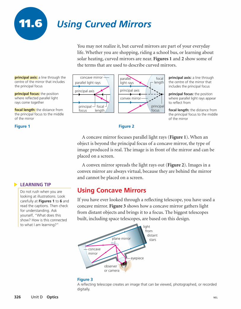
You may not realize it, but curved mirrors are part of your everydaylife. Whether you are shopping, riding a school bus, or learning aboutsolar heating, curved mirrors are near. Figures 1 and 2 show some ofthe terms that are used to describe curved mirrors.
A concave mirror focuses parallel light rays (Figure 1). When anobject is beyond the principal focus of a concave mirror, the type ofimage produced is real. The image is in front of the mirror and can beplaced on a screen.
A convex mirror spreads the light rays out (Figure 2). Images in aconvex mirror are always virtual, because they are behind the mirrorand cannot be placed on a screen.
Using Concave MirrorsIf you have ever looked through a reflecting telescope, you have used aconcave mirror. Figure 3 shows how a concave mirror gathers lightfrom distant objects and brings it to a focus. The biggest telescopesbuilt, including space telescopes, are based on this design.
principal axis: a line through the centre of the mirror that includes the principal focus
principal focus: the position where reflected parallel light rays come together
focal length: the distance from the principal focus to the middle of the mirror
parallel light rays
principal axis
principalfocus
focallength
concave mirror
Figure 1
principal axis: a line through the centre of the mirror that includes the principal focus
principal focus: the position where parallel light rays appear to reflect from
focal length: the distance from the principal focus to the middleof the mirror
light rays focal
length
principalfocus
principal axis
convex mirror
parallel
Figure 2
plane mirror
light from distant stars
eyepiece
observeror camera
concavemirror
Figure 3A reflecting telescope creates an image that can be viewed, photographed, or recordeddigitally.
LEARNING TIPDo not rush when you arelooking at illustrations. Lookcarefully at Figures 1 to 6 andread the captions. Then checkfor understanding. Askyourself, “What does thisshow? How is this connectedto what I am learning?”
11.6 Using Curved Mirrors 327NEL
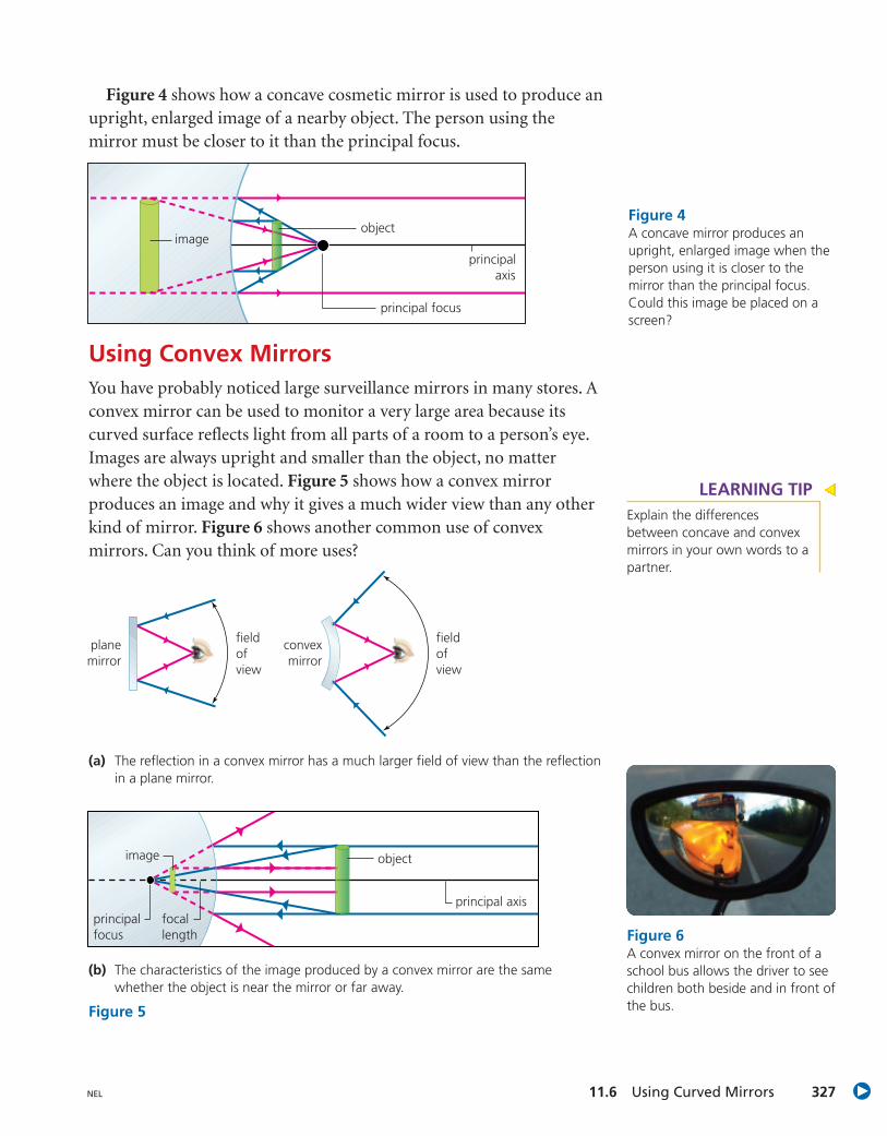
Figure 4 shows how a concave cosmetic mirror is used to produce anupright, enlarged image of a nearby object. The person using themirror must be closer to it than the principal focus.
Using Convex MirrorsYou have probably noticed large surveillance mirrors in many stores. Aconvex mirror can be used to monitor a very large area because itscurved surface reflects light from all parts of a room to a person’s eye.Images are always upright and smaller than the object, no matterwhere the object is located. Figure 5 shows how a convex mirrorproduces an image and why it gives a much wider view than any otherkind of mirror. Figure 6 shows another common use of convexmirrors. Can you think of more uses?
image
principal focus
principalaxis
objectFigure 4A concave mirror produces anupright, enlarged image when theperson using it is closer to themirror than the principal focus.Could this image be placed on ascreen?
objectimage
principalfocus
focallength
principal axis
planemirror
fieldofview
fieldofview
convexmirror
(b) The characteristics of the image produced by a convex mirror are the samewhether the object is near the mirror or far away.
Figure 5
(a) The reflection in a convex mirror has a much larger field of view than the reflectionin a plane mirror.
LEARNING TIPExplain the differencesbetween concave and convexmirrors in your own words to apartner.
Figure 6A convex mirror on the front of aschool bus allows the driver to seechildren both beside and in front ofthe bus.
Unit D Optics328 NEL
1. Briefly describe how the principal focus in a concave mirror is the sameand how it is different from the principal focus in a convex mirror.
2. How do the characteristics of images in a convex mirror compare tothose in a concave mirror
(a) when the object is close to the mirror?
(a) when the object is far from the mirror?
3. For each situation, state whether the image produced is real or virtual.Explain how you know.
(a) A girl is standing close to a cosmetic mirror while applying lipstick.
(b) An astronomer is looking at an image of the Moon through hertelescope, which has a concave mirror.
(c) A clerk in a drugstore is looking at the image of a customer in asurveillance mirror.
4. Rewrite the following false statements to make them true.
(a) The image in a convex mirror is always real and upright.
(b) When an object is inside the principal focus of a concave mirror, itsimage is inverted and real.
(c) Real images are always located behind the mirror.
5. Curved mirrors can be used to gather light from the Sun and focus it forsolar heating. Draw a diagram that shows how this might work.
6. Do you think the focal length of a concave mirror would increase,decrease, or stay the same if the mirror were made flatter? Use adiagram to help illustrate your explanation.
11.6 CHECK YOUR UNDERSTANDING
What is the purpose of theconcave and/or convex mirrors inyour chosen device?
PERFORMANCE TASK
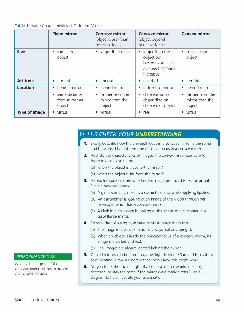
Table 1 Image Characteristics of Different Mirrors
Size
Attitude
Location
Type of image
Plane mirror
• same size asobject
• upright
• behind mirror
• same distancefrom mirror asobject
• virtual
Concave mirror(object closer thanprincipal focus)
• larger than object
• upright
• behind mirror
• farther from themirror than theobject
• virtual
Concave mirror(object beyondprincipal focus)
• larger than theobject butbecomes smalleras object distanceincreases
• inverted
• in front of mirror
• distance variesdepending ondistance of object
• real
Convex mirror
• smaller thanobject
• upright
• behind mirror
• farther from themirror than theobject
• virtual
11.7 Inquiry Investigation 329NEL
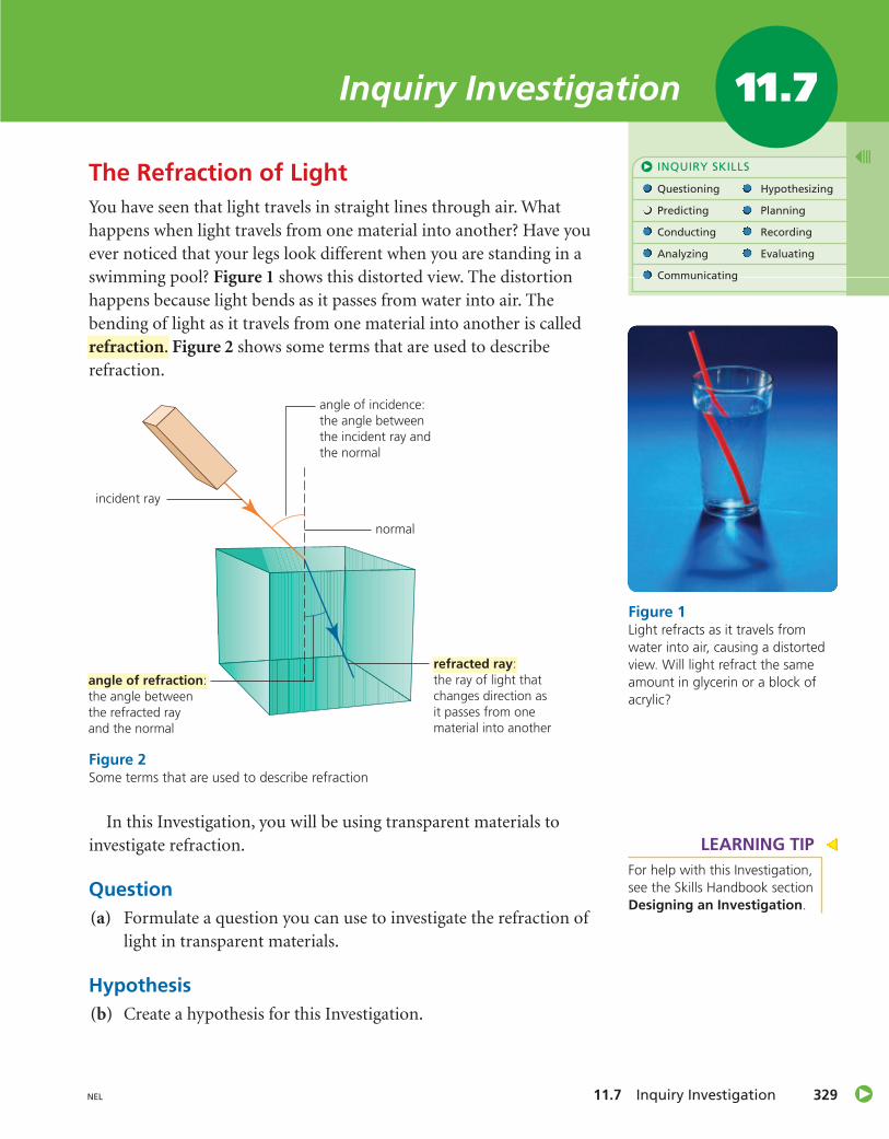
The Refraction of LightYou have seen that light travels in straight lines through air. Whathappens when light travels from one material into another? Have youever noticed that your legs look different when you are standing in aswimming pool? Figure 1 shows this distorted view. The distortionhappens because light bends as it passes from water into air. Thebending of light as it travels from one material into another is calledrefraction. Figure 2 shows some terms that are used to describerefraction.
In this Investigation, you will be using transparent materials toinvestigate refraction.
Question(a) Formulate a question you can use to investigate the refraction of
light in transparent materials.
Hypothesis(b) Create a hypothesis for this Investigation.
INQUIRY SKILLS
Questioning Hypothesizing
Predicting Planning
Conducting Recording
Analyzing Evaluating
Communicating
Inquiry Investigation 11.7
Figure 1Light refracts as it travels fromwater into air, causing a distortedview. Will light refract the sameamount in glycerin or a block ofacrylic?
normal
angle of incidence:the angle betweenthe incident ray andthe normal
angle of refraction:the angle betweenthe refracted rayand the normal
incident ray
refracted ray:the ray of light that changes direction as it passes from one material into another
Figure 2Some terms that are used to describe refraction
LEARNING TIPFor help with this Investigation,see the Skills Handbook sectionDesigning an Investigation.
Unit D Optics330 NEL
Experimental Design(c) Design an investigation to test your hypothesis. You want to
explore refraction as light travels from air into another material,and when light travels from this material back into air. You shouldtest several transparent liquids and at least one solid.
(d) List the materials you will require and the steps you will take,including any safety precautions. Describe how you will recordyour data.
Procedure1. Show your investigation plan to your teacher. With your teacher’s
approval, carry out your investigation. Be sure to wear your apronand safety goggles. Record any changes you make to your plan asyou proceed. Record your observations.
Analysis(e) Light travels in straight lines in air. How does it travel in other
transparent materials?
(f) Compare the angle of refraction as light travels from air into aliquid or solid with the angle of refraction as light travels from a liquid or solid into air.
(g) List the differences between the materials you tested. Speculateabout what property of the materials you tested explains yourresults.
(h) List the materials you tested in order of least refraction to greatestrefraction for light entering from air.
Evaluation(i) In this Investigation, you used a container to hold the liquids. Did
the container affect the results? Support your answer using adiagram.
(j) How could you improve the design of your Investigation?
Clean up any spillsimmediately. Do not touch thelight bulb in the raybox or look directlyinto the light.
• water• glycerin• mineral oil• saltwater solution
• sugar-watersolution
• solid rectangularprism (acrylicblock)
Possible transparent materials:
Is light refracted in your opticaldevice? Why is it necessary torefract the light in this device?
PERFORMANCE TASK
11.8 Refracting Light in Lenses 331NEL
Refracting Light in Lenses
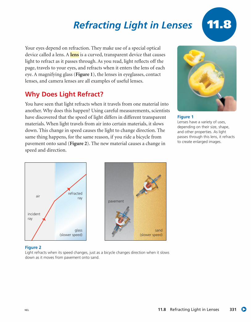
Your eyes depend on refraction. They make use of a special opticaldevice called a lens. A is a curved, transparent device that causeslight to refract as it passes through. As you read, light reflects off thepage, travels to your eyes, and refracts when it enters the lens of eacheye. A magnifying glass (Figure 1), the lenses in eyeglasses, contactlenses, and camera lenses are all examples of useful lenses.
Why Does Light Refract?You have seen that light refracts when it travels from one material intoanother. Why does this happen? Using careful measurements, scientistshave discovered that the speed of light differs in different transparentmaterials. When light travels from air into certain materials, it slowsdown. This change in speed causes the light to change direction. Thesame thing happens, for the same reason, if you ride a bicycle frompavement onto sand (Figure 2). The new material causes a change inspeed and direction.
lens
11.8
Figure 1Lenses have a variety of uses,depending on their size, shape,and other properties. As lightpasses through this lens, it refractsto create enlarged images.
incidentray
glass(slower speed)
airrefracted
raypavement
sand(slower speed)
Figure 2Light refracts when its speed changes, just as a bicycle changes direction when it slowsdown as it moves from pavement onto sand.
Unit D Optics332 NEL
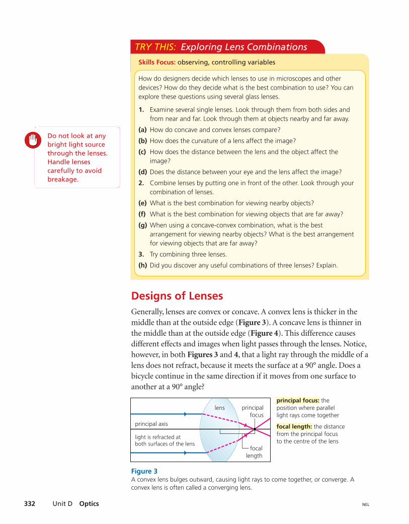
Designs of LensesGenerally, lenses are convex or concave. A convex lens is thicker in themiddle than at the outside edge (Figure 3). A concave lens is thinner inthe middle than at the outside edge (Figure 4). This difference causesdifferent effects and images when light passes through the lenses. Notice,however, in both Figures 3 and 4, that a light ray through the middle of alens does not refract, because it meets the surface at a 90° angle. Does abicycle continue in the same direction if it moves from one surface toanother at a 90° angle?
TRY THIS: Exploring Lens Combinations
How do designers decide which lenses to use in microscopes and otherdevices? How do they decide what is the best combination to use? You canexplore these questions using several glass lenses.
1. Examine several single lenses. Look through them from both sides andfrom near and far. Look through them at objects nearby and far away.
(a) How do concave and convex lenses compare?
(b) How does the curvature of a lens affect the image?
(c) How does the distance between the lens and the object affect theimage?
(d) Does the distance between your eye and the lens affect the image?
2. Combine lenses by putting one in front of the other. Look through yourcombination of lenses.
(e) What is the best combination for viewing nearby objects?
(f) What is the best combination for viewing objects that are far away?
(g) When using a concave-convex combination, what is the bestarrangement for viewing nearby objects? What is the best arrangementfor viewing objects that are far away?
3. Try combining three lenses.
(h) Did you discover any useful combinations of three lenses? Explain.
Skills Focus: observing, controlling variables
Do not look at anybright light sourcethrough the lenses. Handle lenses carefully to avoidbreakage.
principal focus: theposition where parallellight rays come together
focal length: the distancefrom the principal focusto the centre of the lens
principal axis
lens
light is refracted atboth surfaces of the lens
principalfocus
focallength
Figure 3A convex lens bulges outward, causing light rays to come together, or converge. Aconvex lens is often called a converging lens.
11.8 Refracting Light in Lenses 333NEL
The characteristics of convex and concave lenses determine howthey are used in different optical devices. For example, if you want tomake something look bigger, then you should use a convex lens.
Combining LensesSome optical devices, such as microscopes, telescopes, and cameras, usemore than one lens. A microscope, for example, has two lenses—theobjective lens that is close to the object being viewed, and the eyepiecelens that you look through.
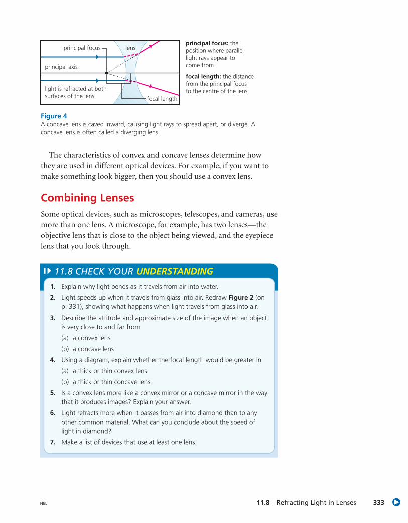
principal focus: theposition where parallellight rays appear tocome from
focal length: the distancefrom the principal focusto the centre of the lens
principal axis
lens
light is refracted at bothsurfaces of the lens
principal focus
focal length
Figure 4A concave lens is caved inward, causing light rays to spread apart, or diverge. Aconcave lens is often called a diverging lens.
1. Explain why light bends as it travels from air into water.
2. Light speeds up when it travels from glass into air. Redraw Figure 2 (onp. 331), showing what happens when light travels from glass into air.
3. Describe the attitude and approximate size of the image when an objectis very close to and far from
(a) a convex lens
(b) a concave lens
4. Using a diagram, explain whether the focal length would be greater in
(a) a thick or thin convex lens
(b) a thick or thin concave lens
5. Is a convex lens more like a convex mirror or a concave mirror in the waythat it produces images? Explain your answer.
6. Light refracts more when it passes from air into diamond than to anyother common material. What can you conclude about the speed oflight in diamond?
7. Make a list of devices that use at least one lens.
11.8 CHECK YOUR UNDERSTANDING
Unit D Optics334 NEL
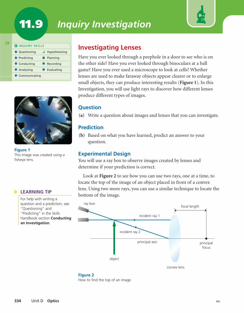
Investigating LensesHave you ever looked through a peephole in a door to see who is onthe other side? Have you ever looked through binoculars at a ballgame? Have you ever used a microscope to look at cells? Whetherlenses are used to make faraway objects appear clearer or to enlargesmall objects, they can produce interesting results (Figure 1). In thisInvestigation, you will use light rays to discover how different lensesproduce different types of images.
Question(a) Write a question about images and lenses that you can investigate.
Prediction(b) Based on what you have learned, predict an answer to your
question.
Experimental DesignYou will use a ray box to observe images created by lenses anddetermine if your prediction is correct.
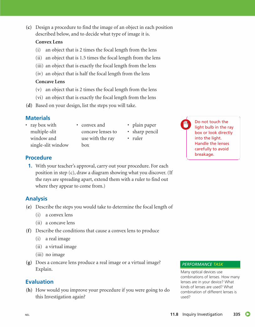
Look at Figure 2 to see how you can use two rays, one at a time, tolocate the top of the image of an object placed in front of a convexlens. Using two more rays, you can use a similar technique to locate thebottom of the image.
INQUIRY SKILLS
Questioning Hypothesizing
Predicting Planning
Conducting Recording
Analyzing Evaluating
Communicating
Inquiry Investigation11.9
Figure 1This image was created using afisheye lens.
ray box
object
incident ray 1
incident ray 2
principal axis
convex lens
focal length
principalfocus
Figure 2How to find the top of an image
LEARNING TIPFor help with writing aquestion and a prediction, see“Questioning” and“Predicting” in the SkillsHandbook section Conductingan Investigation.
11.8 Inquiry Investigation 335NEL
(c) Design a procedure to find the image of an object in each positiondescribed below, and to decide what type of image it is.
Convex Lens
(i) an object that is 2 times the focal length from the lens
(ii) an object that is 1.5 times the focal length from the lens
(iii) an object that is exactly the focal length from the lens
(iv) an object that is half the focal length from the lens
Concave Lens
(v) an object that is 2 times the focal length from the lens
(vi) an object that is exactly the focal length from the lens
(d) Based on your design, list the steps you will take.
Procedure1. With your teacher’s approval, carry out your procedure. For each
position in step (c), draw a diagram showing what you discover. (Ifthe rays are spreading apart, extend them with a ruler to find outwhere they appear to come from.)
Analysis(e) Describe the steps you would take to determine the focal length of
(i) a convex lens
(ii) a concave lens
(f) Describe the conditions that cause a convex lens to produce
(i) a real image
(ii) a virtual image
(iii) no image
(g) Does a concave lens produce a real image or a virtual image?Explain.
Evaluation(h) How would you improve your procedure if you were going to do
this Investigation again?
Do not touch thelight bulb in the raybox or look directlyinto the light.Handle the lenses carefully to avoidbreakage.
Materials• ray box with
multiple-slitwindow andsingle-slit window
• convex andconcave lenses touse with the raybox
• plain paper• sharp pencil• ruler
Many optical devices usecombinations of lenses. How manylenses are in your device? Whatkinds of lenses are used? Whatcombination of different lenses isused?
PERFORMANCE TASK
Unit D Optics336 NEL
CHAPTER
11 Review Mirrors and Lenses
Vocabularyplane mirrors, p. 313
incident ray, p. 313
angle of incidence,p. 313
normal, p. 313
reflected ray, p. 313
angle of reflection,p. 313
point of incidence,p. 313
specular reflection,p. 316
laws of reflection,p. 317
diffuse reflection,p. 317
optical device, p. 319
real image, p. 319
virtual image, p. 319
convex, p. 323
concave, p. 323
principal axis, pp. 326,332
principal focus, pp. 326,332
focal length, p. 326
refraction, p. 329
refracted ray, p. 329
Key Ideas
Light reflects off surfaces in a predictable way.
• Reflection off a smooth surface is called specular reflection.
• The first law of reflection states that the angle of reflection is equal tothe angle of incidence.
• The second law of reflection states that the incident ray, the normal,and the reflected ray all lie in the same plane.
• Reflection off an irregular surface is called diffuse reflection.
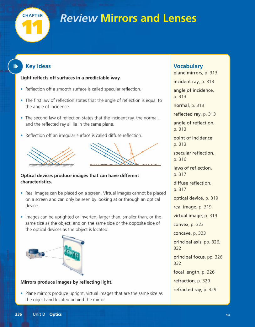
Optical devices produce images that can have differentcharacteristics.
• Real images can be placed on a screen. Virtual images cannot be placedon a screen and can only be seen by looking at or through an opticaldevice.
• Images can be uprighted or inverted; larger than, smaller than, or thesame size as the object; and on the same side or the opposite side ofthe optical devices as the object is located.
Mirrors produce images by reflecting light.
• Plane mirrors produce upright, virtual images that are the same size asthe object and located behind the mirror.
Chapter 11 Review 337NEL
• Concave mirrors produce larger, real images when the object is fartherthan the principal focus. They produce virtual images when the object isnearer than the principal focus.
• Convex mirrors always produce upright, virtual images that are smallerthan the object and located behind the mirror.
When light passes through a transparent material, it may changedirection.
• When light passes from one material to another, its speed may change.This causes the light to refract, or change direction.
• The greater the change in speed, the more light refracts.
Lenses produce images by refracting light.
• Lenses are curved transparent materials that refract light.
• A concave lens causes light rays to spread apart, or diverge.
• A convex lens causes light rays to come together, or converge.
• Microscopes, telescopes, binoculars, and cameras use mirrors or lenses,or a combination of mirrors and lenses, to observe objects.
• Optical devices are used to make distant objects appear closer, to makesmaller objects appear larger, and to capture images of objects.
angle of refraction,p. 329
lens, p. 331
principal axis
lens
light is refracted at bothsurfaces of the lens
principal focus
focal length
principal axis
lens
light is refracted atboth surfaces of the lens
principalfocus
focallength
parallel light rays
principal axis
principalfocus
focallength
concave mirror
light rays focal
length
principalfocus
principal axis
convex mirror
parallel
principal axis
lens
light is refracted at bothsurfaces of the lens
principal focus
focal length
Unit D Optics338 NEL
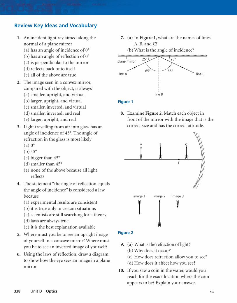
7. (a) In Figure 1, what are the names of linesA, B, and C?
(b) What is the angle of incidence?
8. Examine Figure 2. Match each object infront of the mirror with the image that is thecorrect size and has the correct attitude.
9. (a) What is the refraction of light? (b) Why does it occur?(c) How does refraction allow you to see?(d) How does it affect how you see?
10. If you saw a coin in the water, would youreach for the exact location where the coinappears to be? Explain your answer.
Review Key Ideas and Vocabulary
1. An incident light ray aimed along thenormal of a plane mirror (a) has an angle of incidence of 0°(b) has an angle of reflection of 0°(c) is perpendicular to the mirror(d) reflects back onto itself(e) all of the above are true
2. The image seen in a convex mirror,compared with the object, is always (a) smaller, upright, and virtual (b) larger, upright, and virtual(c) smaller, inverted, and virtual(d) smaller, inverted, and real(e) larger, upright, and real
3. Light travelling from air into glass has anangle of incidence of 45°. The angle ofrefraction in the glass is most likely (a) 0°(b) 45°(c) bigger than 45°(d) smaller than 45°(e) none of the above because all light
reflects
4. The statement “the angle of reflection equalsthe angle of incidence” is considered a lawbecause(a) experimental results are consistent (b) it is true only in certain situations (c) scientists are still searching for a theory(d) laws are always true(e) it is the best explanation available
5. Where must you be to see an upright imageof yourself in a concave mirror? Where mustyou be to see an inverted image of yourself?
6. Using the laws of reflection, draw a diagramto show how the eye sees an image in a planemirror.
plane mirror
line B
line A line C65° 65°
25°25°
Figure 1
F
A B C
image 1 image 2 image 3
Figure 2
Chapter 11 Review 339NEL
Think Critically
18. Why is diffuse reflection more importantthan regular reflection in our everyday lives?Present your evidence in a short paragraph.
19. Name at least two applications of concaveand convex mirrors that are not listed in thetext. Describe why you think they werechosen for this application.
20. Suppose that you want to buy one of thefollowing devices: a telescope, a microscope,a camera, or binoculars. Make a list ofquestions you would ask the salesperson inorder to help you decide.
21. What problems occur when printing orwriting is seen in a mirror? What could youdo to read printing when looking in amirror?
22. What safety problems can occur when usinga convex mirror? List situations in which aconvex mirror should not be used.
23. Write a paragraph that summarizes yourobservations about images produced byconcave and convex lenses.
Reflect on Your Learning
24. How do you think your everyday life wouldbe affected if concave lenses weren’tavailable? Give examples to illustrate youranswer.
25. Write a short paragraph describingexamples of how the reflection of lightmakes the natural world more beautiful andmore enjoyable.
Visit the Quiz Centre at
Use What You’ve Learned
11. Draw a top-view diagram to show how youwould place a mirror in order to see arounda corner.
12. How could you use a curved mirror to starta campfire on a sunny day? Draw a diagramto illustrate your answer.
13. Satellite dishes are used to reflect energyfrom a satellite so that it comes to a focus.What type of reflector is a satellite dish?Using your knowledge of reflection fromcurved surfaces, draw a diagram to showhow this device works.
14. Identify 10 ways that the reflection of light isused in everyday situations.
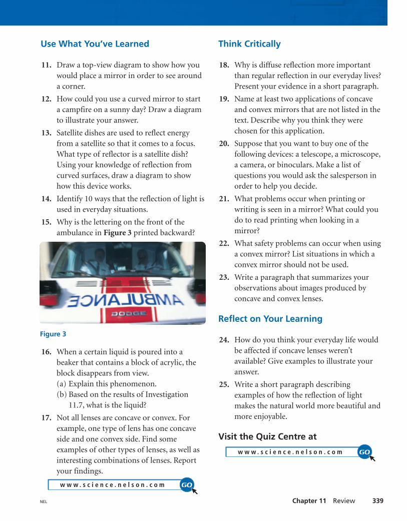
15. Why is the lettering on the front of theambulance in Figure 3 printed backward?
16. When a certain liquid is poured into abeaker that contains a block of acrylic, theblock disappears from view.(a) Explain this phenomenon.(b) Based on the results of Investigation
11.7, what is the liquid?
17. Not all lenses are concave or convex. Forexample, one type of lens has one concaveside and one convex side. Find someexamples of other types of lenses, as well asinteresting combinations of lenses. Reportyour findings.