61

SUDp!Utpei OD!AJOS JOA SZIOISISNVILL Olava W1/WV
001-18 4111•11111111111ft. 1-1 lax-1011m /111111111111111111L
MITINITIMINENOM govnusinsi
ILA 11:411 MEI Mr-11111111111111V
anellat"'\1111/rw
11 4tiii)

The Tele-vue Trouble-Shooter
Instructions for Using
Simply determine the type of Radio you are working on. Either AC-AC/DC-PORTABLE-CAR-or TRANSISTOR. Check index for that type, and locate trouble you have in set. Turn to chart indicated.
AC/DC SECTION
Symptom Chart No.
Hum Howls Squeals Motorboating 2 Distortion on All Stations 3 Distortion on Some Stations 4 Distortion After Set Warms Up 5 Distortion as Volume Increased 6 Weak Sound 7 No Sound 8 & 9 Tubes Do Not Light 10 One Station All Over Dial 11 Reception on One Half of Dial 12 Scraping Sound as Dial Moved 13 Stations at Wrong Point on Dial 14 Intermittent Operation 15 Rattles and Vibrations 16 Noisy Operation 17 Rectifier Keeps Burning Out 18 Some Tubes Do Not Light 19 IF Alignment 20 RF Alignment 21
1
CAR RADIO SECTION
Symptom Chart No.
Hum Howls Squeals Motorboating 2 Di stortion on All Stations 3 Distortion on Some Stations 4 Distortion After Set Warms Up 5 Distortion as Volume Increased 6 Weak Sound 7 No Sound 8 & 9 One Station All Over Dial 11 Reception on One Half of Dial 12 Stations at Wrong Point on Dial 14 Intermittent Operation 15 Rattles and Vibrations 16 Noisy Operation 17 IF Alignment 20 RF Alignment 21 Tubes Do Not Light 24 Radio Keeps Blowing Fuses 25 Sound Fades In and Out 26
1
3 WAY PORTABLE SECTION
Symptom Chart No.
Hum 1 Howls Squeals Motorboating 2 Distortion on All Stations 3 Distortion on Some Stations 4 Distortion After Set Warms Up 5 Distortion as Volume Increased 6 Weak Sound 7 One Station All Over the Dial 11 Reception on One Half of Dial 12 Scraping Sound as Dial Moved 13 Stations at Wrong Point on Dial 14 Intermittent Operation 15 Rattles and Vibrations 16 Noisy Operation 17 IF Alignment 20 RF Alignment 21 No Sound 27 Selenium or Silicon Rectifiers 28 Plays on Battery, Not on AC 29 Plays a Moment, Then Stops 30
AC SECTION
Symptom Chart No.
Hum 1 Howls Squeals Motorboating 2 Distortion on All Stations 3 Distortion on Some Stations 4 Distortion After Set Warms Up 5 Distortion as Volume Increased 6 Weak Sound 7 No Sound 8 & 9 One Station All Over Dial 11 Reception on One Half of Dial 12 Scraping Sound as Dial is Moved 13 Stations at Wrong Point on Dial 14 Intermittent Operation 15 Rattles and Vibrations 16 Noisy Operation 17 Rectifier Keeps Burning Out 18 IF Alignment 20 RF Alignment 21 Tubes Do Not Light 22 Smoking, Overheating Transformer 23
TRANSISTOR SECTION
Symptom Chart No.
No Sound 31 Weak Sound 32 Howls Squeals Motorboating 33 Distortion on All Stations 34 Distortion on Some Stations 35 Intermittent Operation 36 Plays a Moment, Ther Stops 37 Batteries Used Up Too Fast 38 Noisy Operation 39 AI ignment 40
NATIONAL TECHNICAL
RESEARCH LABORATORIES
W UI TTI D r Aiir no w A

Tilt INACTICAL APPROACH TO RADIO THEORY INTRODUCTION
The material contained in the Tele-Vue troubleshooter was obtained under shop conditions. Radios brought in for repair were checked using the same time proved tech-niques as are used in top quality shops all over the nation. From the hundreds and thousands of cases tested it was soon evident that troubleshooting is a case of cer-tain quick checks to determine the defective sections, then voltage and resistance analysis to locate the de-fective component. The same procedures were used over and over again, and always the same answer, use certain quick checks, then voltage and resistance analysis. This system has been captured for you in the Radio Tele-Vue Troubleshooter.
REVIEW OF RADIO
Sound waves produced in the studio, pass across the mi-crophone. The microphone turns these sound waves into electrical impulses that are amplified by an audio ampli-fier. Since audio cannot be transmitted, it is necessary to combine the audio with a high frequency carrier. In the broadcast band, the carrier frequency can range from a low of 550 kc, to a high of 1600 kc. Each radio station is assigned a frequency by the F.C.C. The combined sig-nal, called a MODULATED signal, is passed through the air in the form of electromagnetic waves travelling at the speed of light, refer to Fig. 1.
MICROPHONE
560 KC
TO
1600 KC
E L E C' ROM AGNETIC
WAVES
FIG. I
The modulated signal is picked up by the antenna, and is
either amplified by an RF amplifier, or passed directly
to the MIXER. Also going into the mixer is a signal pro-
duced in the radio itself called the LOCAL OSCILLATOR
signal. The combination of the incoming modulated signal
and the local oscillator signal in the mixer, produces the
Intermediate Frequency commonly called the I.F. A radio
station signal CANNOT pass through the I.F.s unless
it has first mixed with the local oscillator signal. The
I.F. signal is amplified by the I.F. amplifier, and then
passed to the detector. It is the purpose of the detector
to remove the carrier that has brought the audio signal
to the radio receiver, and to pass the audio signal to the
audio amplifying stages. After leaving the detector, the
signal is amplified greatly by the 1st audio amplifier,
then is passed to the audio output circuit.
It is the job of the audio output stage to provide the
power necessary to operate the loudspeaker, that is why
sometimes the audio output stage is called the Power out-
put. Once the signal has left the output stage, it goes to
the last link in the radio chain, namely the Loudspeaker.
Here the signal is turned back into sound waves, just as
they were when they entered the microphone back in the
broadcasting studio, see Fig. 2.
R.F AMP
4144611410
MIXER
4
LOCAL
OSC.
44V1641111 AMP
and, if we have the use of a signal generator, locating the defective stage should hold no problems at all. Let us dwell on the signal generator for a moment. If a radio is not functioning correctly, it would be of great advan-tage to us if we could say for sure that the audio circuits are operating normally, or that the I.F. amplifier is doing its job. This is possible if we use the signal generator because it is a device that is capable of providing a signal for us that can take the place of the signal normally passing through the radio. For example, if a radio has no sound, we can connect the signal generator at the grid of the audio output stage and feed in an audio signal from the generator. If we hear that signal coming out of the loudspeaker WE WILL KNOW THAT THE AUDIO OUTPUT STAGE AND THE SPEAKER ARE WORKING. Now, this fact alone is invaluable to us because we need not waste any time at all in checking these circuits. The same con-ditions are applied to each and every circuit in the radio receiver. We can check to see if the 1st audio stage is working, or the I.F. amplifier, oscillator, or mixer stage. The generator can also be used to find the solution to weak sound, intermittent sound, fading, alignment, etc. When we come to the stage that doesn't pass the signal as it should, then all efforts are concentrated on that
— IP DETECTOR
A. V. C.
FIG. 2
circuit until the defective component is found. This meth-od of troubleshooting eliminates unnecessary checks and provides a SURE FIRE answer to receiver troubles. The Tele-Vue Troubleshooter is based upon these procedures, although it is also possible to approach the troubles with-out the use of the signal generator. This is done for the
TROUBLESHOOTING PROCEDURES
In troubleshooting a radio receiver, it is always a good idea to have in mind the overall radio system as described in the radio review. The reason for this, is that a faster method of isolating the source of trouble is possible if we understand the purpose of each section of the radio,
AUDIO AMP
/1}
POWER SUPPLY
AUDIO OUT.
SOUND
WAVES

benefit of those that do not have a generator available.
The steps found most desirable, and producing the best results, are listed here at this time so that a discussion on the reasons for them can be given to see how they tie in to our overall troubleshooting procedure.
1. Visual inspection 2. Tube substitution 3. Signal injection 4. Voltage and resistance checks 5. Component substitution
Let us discuss them one at a time.
VISUAL INSPECTION
This can be done as we are in the process of removing the set from the cabinet, or even before that, by looking the set over as we listen to the trouble. Often such things as a broken antenna wire, loose tube in its socket, or a corroded electrolytic capacitor, can be easily noticed and corrected without using any of the instruments at all. If the set has to be removed from the cabinet, then such things as broken or burned resistors, poor solder con-nections, a broken wire, a loose component, can be seen and the repair effected without too much difficulty, and certainly with profitable results.
TUBE SUBSTITUTION
For the professional technician, tube substitution is very important. According to national surveys, over 60% of all troubles in radio are caused by tube failure. If this is true, then we are taking a better than average chance that a tube is the cause of the trouble in the radio you are working on. Of course the thought comes to mind, How many tubes must I have on hand in order to be able to substitute them in a radio receiver? Well, in radio the answer is, very few. Most AC/DC receivers use one of the two following tube lists. The older types used 35Z5, 50L6, 12SK7, 12SA7, 12SQ7. Modern types use 35W4, 5005, 12BA6, 12BE6, 12AV6. AC receivers use 5114 or 5Y3 or sometimes 6X5, 6V6, 6SQ6, 6SK7, 6SA7. The 3 way portable often uses 3V4 or 3S4, 11.15, 1114 or 1T4, 1115 or 1L6. As for the car radio it uses the same tubes as the AC type, or in a 12 volt system, it will use the same tubes as the 12 volt AC/DC tubes. The exception to this is the rectifier, in a car radio it is either the OZ4, 6X5, or the 6X4. The output tube in the 12v car system will be the 12V6.
SIGNAL INJECTION
Of course, we have already indicated the importance of using a signal generator, now we find that if we have had a visual inspection, and the tubes have been substituted. we should proceed to try and find the defective stage.
This can be done with the generator, starting at the audio output stage and working back toward the antenna.
VOLTAGE AND RESISTANCE CHECKS
Once the trouble is isolated to a defective stage, voltage readings should be taken. With a little thought, any voltage reading of a defective stage will almost pinpoint the defective component, or at least isolate it to a few parts. Let us take an example. Suppose that a radio had no sound, and after the visual check, tube substitution, and signal injection, we find that the 1st audio amplifier is not passing the signal. If it is an AC/DC receiver, the operating voltages should be as follows: Plate — 55v. Grid — -1v. Cathode — Ov. If the measured values were Plate — Ov, grid — Ov, cathode — Ov, we must suspect either an open plate resistor, or a shorted plate capacitor if one is used. The fact that the grid voltage should be -1v, and is now Ov, should be ignored because if there were no plate voltage, then the -1v will not be present on the grid, since in the 1st audio stage the bias is provided by current flowing through the tube, and with no plate voltage, there will be no current. From the voltage read-ings we determine the path of trouble in the stage, either the cathode, screen, control grid, or plate. Then resist-ance checks are made to find the defective part.
COMPONENT SUBSTITUTION
Once the defective part has been determined, usually by a resistance check, it must now be replaced. However, this may not be as easy as one might think. As far as resistors are concerned, the three things to keep in mind are: 1) Resistance value. 2) Wattage rating. 3) Physical size. The resistance value should be the same as the one in the set. If the resistor is charred beyond recogni-tion, refer to the manufacturers schematic, or contact the local wholesaler and give the model number, and resistor location, such as, plate resistor of the 1st audio amplifier, and they will be able to find the resistor value for you. As far as the wattage goes, it must be the same value or larger, than the one in the receiver, never a smaller wattage. Remember, the wattage rating of a resistor de-tennines its ability to dissipate the heat. If it is too small, it will overheat and burn up. One thing of impor-tance to mention at this time is that if a resistor is burned or charred, you should investigate the reason for this, since a resistor by itself cannot burn up, something (usually a shorted capacitor), has caused this to happen. The final point to discuss is the physical size of the resistor. You should always be sure that the resistor will fit into the space provided for it. In most radios of the AC/DC and AC type, this is not much of a problem, but
in some of the small portable and transistor radios, space is at a premium.
If the defective component is a capacitor, we must check for 1) Capacity value. 2) Working voltage. 3) Physical size. If a capacitor is used for coupling, or to bypass a signal, the same capacity as the one in the circuit or slightly larger will do. For example, if the avc bypass capacitor has to be replaced, and its value is .05 mfd, replacing it with a .1 mfg will be alright, this is double the value, but since it is there to bypass a signal, being a larger value will make it do its job that much better. When the capacitor is in the RF, Mixer, or Local Oscil-lator circuit, then exact values should be used. As for the voltage rating, these values should never be less than that of the one in the circuit. In fact, in almost all instances, it is perfectly alright to use a larger working voltage than the one that was in the circuit. The excep-tion to this is in the case of electrolytics. These must be about the same working voltage as the one they are replacing. The reason for this, is that it has been found that the dielectric (insulator between the plates), will deteriorate if the voltage applied to it is much lower than its normal working voltage. As for size, the same things apply to the capacitor as have been mentioned for the resistor.
Finally, we come to coils and transformers. Here we have the problem of step up or step down ratio, and of imped-ance matching. Great care should always be taken to make sure that the replacement part IS a replacement for the transformer or coil in question. Even in the case of a defective I.F. transformer, you must specify whether it is the input or the output transformer when ordering the new I.F. The input transformer is the one going from the plate of the mixer, to the grid of the I.F. amplifier. As for output transformers they can be replaced in most cases with a universal type, if the exact replacement is not available. A chart comes with the universal type that shows the correct connections for the particular type of circuit you have in the receiver.
The information covered here, together with the introduc-tion to the operation of the Transistor and FM, the trouble-shooting digests on each chart, and the check points in the charts themselves, should enable you to become a competent service technician.
l'AGE 2

Thi rRAciTIGAL APri?Wlett To IKANSISIOk THEOd INTRODUCTION
The purpose of this material, is to acquaint the reader with sufficient information to enable him to troubleshoot transistorized radios in the service field. Today, the transistor is becoming more and more a part of everyday servicing, and it is important that the technician have the ability to understand and work with the transistor re-ceiver.
"N" AND "P" TYPE GERMANIUM
Due to the atomic structure of germanium, it is found in crystal form. This means that groups of atoms are cling-ing together to form a crystal. By itself the germanium crystal is an insulator. A group of scientists working for the Bell telephone company in the late forties, found that by adding small amounts of material to the germanium crystal, they could turn the germanium into a semi-con-ductor that would allow an electron flow, or "hole" flow, through the crystal. A "hole" flow is considered as an electron from one atom, filling the outer orbit of another atom, thus leaving "hole" in one atom that it left. This action is mentioned here, because by germanium havilig "hole" movement, it is quite different than germanium having an electron movement. In order to tell them apart, the germanium with the electron movement is called "N" type, and germanium with hole movement is called "P" type. If a piece of germanium of the "N" type is placed in contact with a piece of "P" type, and a battery is placed across the two, current flow will occur. Refer to FIG. la.
If the battery is reversed as shown in FIG. lb, current flow will stop. The reason for this is that in FIG. la, the negative terminal of the battery is forcing electrons from the "N" section into the "P" section, where they will go from hole to hole and back to the positive terminal of
the battery. In FIG. lb, the electrons from the "N" sec-tion are being pulled away from the "P" section, by the positive terminal of the battery, therefore they cannot
complete the circuit, and current flow will stop.
FORWARD AND REVERSE BIAS
When the battery is connected as in FIG. la, we say that the crystal has FORWARD BIAS. Perhaps a good way to remember this, is to note that the negative terminal of the battery is connected to the "N" section, and the positive terminal is connected to the "P" section. When the bat-tery is reversed, FIG. lb, we say the crystal has RE-VERSE BIAS. Perhaps you have heard of a germanium diode?, well the illustration of FIG. 1 can be applied to the germanium diode. It allows current flow in one direc-tion, but stops current flow in the reverse direction. A diode vacuum tube uses this same principle for its opera-tion, however, the advantage of a germanium diode, is that it does not require a heater nor a vacuum, therefore would tend to be longer lasting with less possibility of breakage. When forward bias is applied, the resistance to current flow is low, somewhere in the hundreds of ohms. If reverse bias is used, the resistance to current flow is high, somewhere in the hundreds of thousands of ohms. As a result, we can check a germanium diode by connecting a meter across the diode one way, and then reversing the leads of the meter, one reading should be high, the other low.
FIG I o
THE TRANSISTOR
The transistor is constructed of three sections of ger-manium. It can be either of the "N" "P" "N" type, or the "P" "N" "P" type. One section of the transistor is forward biased, and the other section is reverse biased. The key to the operation of the transistor is the thinness of the middle section, it is usually no more than one thousanth of an inch thick (.001"). Let us refer to FIG. 2 as we discuss its operation.
PROVIDES
FORWAR D
B IAS
• 001" THICK
FI G 2
CPROVIDES REVERSE
BIAS
You will notice that the first section of the transistor is forward biased, and the last section is reverse biased. The forward bias is forcing the electrons in the first "N" section to go into the "P" section. However, because the "P" section is so thin, almost all of the electrons pass right through into the second "N" section. The second section of the transistor is reverse biased, having a high resistance to current flow, but we have forced electrons into the reverse bias section because the middle "P" section is so thin. The extra electrons in the second "N"
section are removed by the positive terminal of the bat-tery, thus completing the path of current flow. What has
happened here, is that the current started by the low re-
sistance forward bias section. has nascrei thrniloh tb

high resistance reverse bias section, this action gives the transistor its amplifying characteristics. By adding some resistors and feeding in a signal, we will have our transistor amplifier. The names, and the amplifier circuit of the transistor amplifier are shown in FIG. 3a. The same circuit, using the transistor symbol, is shown in FIG. 3b.
BASE
COLLECTOR
11
FI G. 3
THE GROUNDED BASE AND GROUNDED EIAMITTER AMPLIFIER
As the input signal varies, it will add and subtract from the forward bias of the first section of the transistor, this will vary the current flow through the whole transis-tor, and cause the collector voltage to vary as the signal varies. However, the varying collector voltage will be an amplified version of the input signal. This type of a cir-cuit is known as the GROUNDED BASE AMPLIFIER, it requires two batteries, and is seldom used today. By far the most popular of the transistor amplifiers is the GROUNDED EMITTER AMPLIFIER, it can be operated with one battery, and has a larger amplifying ability than the other types. The grounded emitter amplifier is used in almost all transistor amplifiers, and will be the one that we shall discuss and use throughout our trouble-shooting charts. The circuit of this type of an amplifier is shown in FIG. 4.
FIG . 4
Since this is the most likely transistor amplifier that you will come across, let us make sure that we understand how it is forward and reverse biased. In order for the for-ward bias to be on the base emitter, the base must be positive with respect to the emitter. As you can see, the emitter is connected to the ground through R2, this con-nects it to the negative side of the battery that is also grounded. The base is connected to the positive side of
the battery through RI. With the base positive, and the emitter negative, we have forward bias. In order to have reverse bias the collector must be positive with respect to the base, Since it is connected to the positive terminal of the battery through R3, it will be positive. The values
of RI and R3, and the current flow through them will de-termine if the collector is more positive than the base, and of course it_must be in order to overate correctly Cl is the coupling capacitor that couples the signal to the base of the transistor. It is a large value electrolytic capacitor so as to couple as much of the signal as possi-ble to the transistor. Electrolytics are NOT used in radio sets of the vacuum tube type because of the higher volt-ages used, and the more likelyhood of breakdown of the capacitor. In transistor radios, the voltage seldom ex-ceeds 9 volts. R2 is used in the emitter circuit to com-pensate for temperature changes and any differences in transistors should it be necessary to replace the transis-tor for any reason. Without R2, a change in temperature, say from a cool room to the hot sand on the beach, would cause the radio to become distorted, or perhaps weak. C2, across R2, keeps the emitter voltage constant for a con-stant value of forward bias.
As the incoming signal is coupled through Cl to the base of the transistor, it will cause the current through the transistor to vary as it adds and subtracts from the for-ward bias. Collector voltage will vary due to the varying current through the transistor, and this varying voltage will couple through C3 to the next circuit. The battery used for this operation is usually a 4 volt or 9 volt type. In some of the amplifiers, C2 is omitted so that a better frequency response is provided. In the RF and IF circuits of a transistor, different methods are used to couple the signal from one transistor to the next. In most cases it will be done by means of transformers, FIG. 5, shows a typical transistor IF amplifier.
I.E AMP )111455 K C go.
455KC
-/-
A.V.C.
FI G. 5
TO BATTE RY
PAGE 2

In most of the detector circuits of a transistor amplifier a germanium diode is used in place of the conventional diode tube, since we have already discussed the opera-tion of the germanium diode, we can go right to the cir-cuit of the detector as shown in FIG. 6.
110
A.V. C.
GERMANIUM
DIODE
I+
FI G. 6
VOLUME CONTROL
TROUBLESHOOTING THE TRANSISTOR RADIO When working on the transistor radio, you will find that the troubleshooting procedures you have used in radios of the vacuum tube type, can be applied to the transistor radio. For example, suppose that a transistor radio were given to you for repair, and after switching on the radio you found that it had no sound. After making sure that the batteries were okay, you would now go to the input of the last transistor in the radio, the audio output transistor, and feed in an audio signal to the base. If you heard a tone, you would proceed to the volume control with the audio generator, and try to pass an audio signal from that point. If a tone is heard, then feed in a modulated IF signal to the base of the IF transistor, if a tone is heard, move back to the base of the next transistor, and so on.
If at any of the above points a tone is NOT heard, why you would troubleshooe that circuit and find out why the the tone did not go through. The above example can be applied to ALL of the troubles found in transistor radios, you simply apply the same procedures that you have used all along.
At first some difficulty raay be experieacea in loca:.,ng the correct transistors to feed a —pal to, or you may find that because most transistor radios are made with the use of printed circuits, that it will take some time to get used to the printed circuit board.
Another point that I know will be hard to adjust to, is the compactness of the entire radio, for as you know, it is the desire of the manufacturer to make these radios as small as possible. Remember, be patient, for all of the above mentioned conditions can be overcome, and the ability to repair transistor radios will, I can assure you, be very profitable to you.
All of the discussion on transistors has been pertaining to the "N" "P" "N" type. If the "P" "N" "P" type of transistor is used, then the battery connections to the transistor and the direction of the arrow of the emitter will be reversed. The base of the transistor is the middle
lead, and the collector is identified by either being far-ther away from the other two leads, or having a colored dot by its lead.

THE PRACTICAL APPROACH TO FM THEORY INDEX AND INSTRUCTIONS FOR USING THE TELE-
VUE TROUBLESHOOTER FOR FM.
Simply determine the chart that covers the trouble occur-ing in the FM receiver from the index of troubles listed
below. Turn to that chart and place plastic cover over
chart so that information, schematic, and photo show
through window in plastic.
Symptom Chart No.
Drifts off Station 41 Intermittent Operation 42 Noisy Operation 43
Di stortion 44 Weak Sound 45 No Sound 46
47 Aligning the Ratio Detector Aligning the Discriminator Aligning the I.Fs Aligning the R.Fs
48 49
50
INTRODUCTION
Frequency Modulation, or more simply FM, has been in-creasing in popularity ever since its introduction in the field. Today, because of Television and High Fidelity, more and more FM receivers are being sold than ever be-fore. As a result, the serviceman is finding more need for an understanding of FM theory and Troubleshooting tech-niques. It is the purpose or this article and subsequent charts, to provide a clear path to the theory and service of FM receivers.
FREQUENCY MODULATION
The outstanding advantages of FM are its low noise factor, and its ability to provide high fidelity. This is possible because of the limiting action of the detector in the receiver, and the high transmitting frequency that is used, (from 88 mc to 108 mc). The carrier frequency that brings the audio signal through the air, has a constant amplitude as it leaves the transmitter. This differs from the Amplitude Modulated signal that is transmitted for our broadcast band, since, as its name implies, it varies in amplitude. As the FM signal passes through the air, it picks up noise impulses, (these are due to arcing of electric motors, etc.), these impulses attach themselves to the top and bottom of the carrier signal, and are brought into the FM receiver along with the signal. However, due to the operation of the FM detector, the amplitude of the
signal is limited, and any noise riding along with the signal is removed. This action cannot be done in AM, because it is the amplitude variations that represent the the audio intelligence. Refer to Fig. 1.
NOISE
I
CLIPPED
NOISE FREE
RE C.
F. M.
DET.
A.M.
DET. REC.
FIG. I
NOISE
T
High Fidelity is possible with FM because the carrier frequency is so high that it permits a relatively large amount of modulation to occur without interfering with other stations. This is not true in AM, since the stations are only a few kilocycles apart.
THE F.M. ANTENNA AND R.F. STAGE
The FM antenna differs from the AM type, in that it re-quires a twin lead in wire connected to a dipole Hertz antenna. For best results the antenna should be mounted on the roof facing the direction of the transmitting an-tenna. However, since many of the stations transmit from different locations, it would require a rotating antenna to be moved as we select various stations. This is unde-sirable for obvious reasons, therefore, the antenna is set to receive as many stations as possible for best all-around results.
In almost all of the FM receivers sold today, some form of indoor FM antenna is provided. This usually consists of twin lead in wire stapled to the inside of the cabinet and attached to the antenna terminals of the set, or ca-pacity coupling from the ac line cord to the antenna term-inals. The latter consisting of a metal clamp around the
ac line cord and connected to the antenna terminals. Refer to Fig. 2.
FIG.2
From the antenna terminals the signal is applied across the antenna coil. This may be in the cathode circuit of a grounded grid triode amplifier, or in the grid circuit of a pentode amplifier.
The disadvantage of the pentode RF amplifier stage is its high noise factor. Even though FM is relatively noise free, it is still undesirable to have noise in the signal. To overcome the disadvantage of the pentode amplifier, an RF amplifier of the triode type is sometimes used. A triode has less noise than a pentode, and the undesirable effect of high interelectrode capacity is almost elimi-nated by feeding the signal into the cathode circuit, and grounding the grid through a capacitor. Both of the cir-cuits mentioned aboved are shown in Fig. 3.
MIXER AND OSCILLATOR STAGES
Heterodyning is used in FM just as it is used in AM, however, due to the higher frequencies, certain differ-ences do exist. The mixer must receive two signals, one from the RF amplifier, and the other from the Local Oscil-lator. We have already noted that the signal from the an-tenna is amplified by the RF stage using a conventional pentode, or a grounded grid triode. From the RF stage, the signal is coupled to the grid of the Mixer. The Mixer. is usually a triode, using one half of a duo-triode tube as

ANT.
(A)
FIG. 3 (B)
TO MIXER
a Mixer, and the other half as an Oscillator, or a single triode operating as a Converter (combination mixer and oscillator). Some of the models are using a duo-triode with one half as an RF amplifier, and the other half as a Converter. The other signal that is applied to the Mixer stage, comes from the Local Oscillator, and is also ap-plied to the Mixer grid. In the cases where the tube is a converter, the signal from the Local Oscillator section is at the Mixer grid simply because the one rube is perform-ing dual functions, Mixer action AND oscillations. Where a separate Oscillator tube is used, the signal will be ap-plied to the Mixer grid either by capacitive or inductive coupling. Fig. 4 shows the various Mixer Oscillator cir-cuits.
The components that are used in the FM Mixer and Oscil-lator, perform the same functions as those found in the AM radio. The actual difference between them is their electrical values. Since FM is a high frequency, the com-ponents will be much smaller and more critical. Great care must be taken to avoid moving parts or rerouting wires, either action could lead to serious misalignment. With both signals present at the Mixer, heterodyning will
occur and the Intermediate Frequency (IF), of 10.7 mc
will be present for the IF transformer in the plate circuit of the Mixer. Fortunately, the IF in FM is standard at 10.7 mc.
FM IFs
The signal passing through the IFs of an FM receiver, is constantly changing frequency with intelligence present. The amount of frequency change permitted in an FM sys-tem for radio is plus or minus 75 kc. This gives a maximum deviation of 150 kc. Compared to the AM deviation with intelligence of only 10 kc, you can readily see that the IFs in FM must be capable of a broad bandwidth. This also calls for very special alignment with instruments. In AM it is possible to align the IFs by listening to the radio station and adjusting the IF screws for maximum sound. This cannot be done in FM. UNDER NO CIRCUM-
STANCES ATTEMPT ALIGNMENT WITHOUT THE COR-RECT EQUIPMENT. Since the bandwidth of the IFs is broad, it is often necessary to use more than one stage of
IF amplification because you must sacrifice amplifica-tion in order to obtain bandwidth. Another point to men-tion at this time is the use of a combination AM/FM re-ciever. Under these circumstances the IFs can handle
V8
&dia.§ FM RF AMP
L4
V9A ,I/2 12 AT7
FM MIXER
moo aovt
Westinghouse
both AM and FM by using a double IF coil in the plate circuit. One will respond to the AM IF, and the other to FM IF. Fig. 5 shows such a circuit.
THE FM DETECTOR
Perhaps one of the greatest differences between the AM receiver and the FM type, is the detector. In AM the de-tector must detect a change in amplitude. In FM, the amplitude of the signal is constant, therefore, an AM detector could not possibly work for an FM signal. In-stead, a special type of detecting circuit is used, one that will detect changes in frequency. Two basic type of FM detectors are in common use today, one is the Dis-criminator, and the other is the Ratio Detector. The Discriminator requires a Limiter stage prior to the de-tector circuit, for purposes of limiting the amplitude of the FM signal being applied to the detector. A schematic diagram of the Limiter is shown in Fig. 6.
The output of the Limiter stage is a constant amplitude signal ready for the detector. The input to the Limiter may have amplitude variations present due to noise and un-even amplification of the tubes that the signal has passed through. Limiting action is accomplished by using grid
FIG. 4
CP LS —
1.1111.1 MU M 0/ IN 'IR MO
„ Of
19CLBA
FM TUPER UNIT
IS
'N M
MEI MS et, e.•
0
CI. <II
1/2 19CL8A MIXER -OSC
11.
PAGE 2 A dmaral

V3 68A6 68A6
FM IF AMP FM-AM IF AMP L.,.
leak bias provided by R13 and C20, the action is as fol-lows. Signal applied to grid of limiter will cause grid current to flow on positive half cycle, this will charge C20 to peak of signal. As signal goes into negative half cycle, C20 will discharge through R13 and develop a voltage across R13 that will cut limiter tube off. The
entire negative half cycle of input signal will not pass through tube because it is in this state of cut-off. When the Limiter stage conducts on the positive half cycle, the tube is driven into saturation because of low plate voltage due to the large value of R18. Therefore, both
V3 V4 bilAn ISAU6
FM AM IF AMP FMtIMITIR
tf,,torola
F I .6
the top and bottom of the input signal have been clipped, and only a small portion of the entire signal will pass through the Limiter stage, giving us a constant amplitude limited output. All of this action is necessary because the Discriminator WILL detect changes in amplitude if any are present, and the result of this would be noise. Taking this one step further, if a weak signal is applied to the Limiter stage, and it does not limit the signal properly, some amplitude changes will get through and cause noisy reception. Therefore, an FM receiver using a Limiter and Discriminator will only perform well if the signal is strong enough to provide correct Limiting ac-tion. Let us now refer to Fig. 7 to study the operation of the Discriminator.
DISC.
The theory behind the operation of the Discriminator is quite complex and beyond the scope of this material. However, we will be able to have a very good understand-ing of its operation for practical and troubleshooting
purposes. To begin with, we know that the signal applied to the detector transformer from the Limiter is of a con-stant amplitude. The signal is now coupled to the two plates of the Discriminator. If only the IF signal is pres-ent, then both tubes will conduct equally and produce equal voltages across R2 and R3, but due to the direction of current flow through each resistor, the total voltage across both of them will be zero. This is as it should be, since with only the IF present, there is no modulation, and therefore no output. As the frequency varies above and below the IF due to modulation, the signal at the plates of the Discriminator will no longer be equal, this is due to circuit design and operation, and one of the diodes will conduct more than the other. This will pro-duce an unequal voltage across R2 and R3, and their combined value will no longer be zero and there will, be an output. Since the modulation will cause the frequency to vary above and below the IF at an audio rate, the out-put of the Discriminator will be an audio signal. Once detected, the signal is applied to a deemphasis network
that compensates for certain changes in the high audio frequencies that are transmitted. The deemphasis network consists of a resistor and capacitor combination that bypasses some of the high audio frequencies to ground, and provides a uniform output for all frequencies. From the deemphasis network the signal is applied to the vol-ume control. Once at the volume control the circuit be-comes identical with any audio amplifier found in AM.
The second type of detector is the Ratio detector, and is perhaps the more common of the two since it has less circuitry, for example it does not require a Limiter stage before the detector. The Ratio detector is also a double diode, but in this instance the signal is applied to the cathode and plate of the two diodes rather than to the two plates as in the case of the Discriminator. At the far right of the diagram in Fig. 8, you will notice an elec-trolytic capacitor, this capacitor absorbs amplitude varia-tions of the signal. Its value is usually between 4 and 8 mfd and is often called a stabilizing capacitor. The oper-ation of the Ratio detector is somewhat similar to the operation of the Discriminator with the exception of the output points. In the Ratio detector, with only the IF ap-plied, both biodes conduct equally and charge C25 and C26 the same amount. The output is tapped off between these two capacitors, with the other lead at ground. When the modulation is present, the two diodes do not conduct equally, and the charge on C25 and C26 will no longer'be equal. This unbalances the circuit, and an output is noticed. It is the ratio of charge on C25 and C26 that pro-duces the output from the Ratio detector circuit. There are a number of ways of producing an output from the Ratio detector circuit, but one can always recognize that it is a ratio detector by the use of the electrolytic ca-pacitor and the detector transformer connecting to the cathode and plate of the two diodes. The output of the ratio detector is applied to the deemphasis network, just as with the Discriminator, and from there to the volume control. Once again, the audio circuit is identical with the circuit found in any AM receiver.
RAt10 DIP
PAGE 3

TROUBLESHOOTING THE FM RECEIVER
Troubleshooting the FM receiver is in most cases similar to that used in AM. Some of the differences come in the IFs and alignment. As far as the audio section of the FM receiver is concerned, there are no differences at all. In trying to pass a signal through the IFs however, it be-comes necessary to set the generator at 10.7 mc with modulation, and then rock the dial back and forth around that frequency. The reason for this, is that at the IF of 10.7 mc, there should be no output, and only by rocking the dial will an output be possible. As for the alignment, great care must be taken in aligning the detector. This
3005
I.
LI M M OWN IN LINE
POSETION
INC LINE
117V AC
r - • • •
NNE
; 47
Le &eve
FM TUNER
U tirit ER
R13
140V
47
Ti
1M 900 4 W
can be done with the generator and VTVM, or for an even better alignment an oscilloscope can be used. Once again to repeat, do not attempt alignment without the proper instruments.
Since many of the F.M. receivers sold today are of the combination AM/FM type, it will be worth while to dwell upon some troubleshooting features of these receivers so that we may make use of their dual operation. In the com-bination receiver, the audio circuits are common to both AM and FM. If for some reason the FM section is in-operative, and yet the AM is working, we will already have a clue as to the area of trouble. For example, we
- I '1"- 001
totms— — itsM — 12Fag— O M 7
4 3 5 4 4 4 3 C25 •
13
BOTTOM NEVI
1001
NO 4.70
027
1.04
TVI
146 100 7
6Nif s
Ti
2sd. W. AMR
I. writ. A 171A. FRON •Oom TS .4.04C•710 '0 6_, To me: iNCouC 7•NCE AT 1.•■10aut.. 100.. UNE CONTROL AT WIN 'Num, LINE VOLTA-- • T 117 V • C. NO SIGNAL INPUT.
2. ALL C••• Ce TANCE VALUES ARE IN INFD. 111 ALL RESISTANCE VALUE S ARE IN OWNS Ve WAT um.Ess sTAito ormistnst. ruSIIILE •E NSTOR, AAAAA CC ONLT •114 b(51 AC.OuSE APPRovE0 IAVT
14 Av.
SON DOT
MOTION NEW
T•
_
its IN
VOL . CONT. TAPPED
AT •OOK
Re 120 •
330
68
will know that the audio circuit is working, and that the power supply is okay, now, with a few other checks, we can determine the actual area that is defective. Another example of troubleshooting can be seen if we consider an AM/FM combination that is completely inoperative. This should lead us to the conclusion that the trouble is common to both sections, and continuing the thought, this must be either the audio section or the power supply. The troubleshooting charts indicate the checks that should be made for a combination AM/FM receiver, or for an FM type.
v 3
1 03 •.7 NWF
25
57 IN
Net./W
Aulahlapo
Courtesy of Westinghouse Tech-Lit Service.
T5
Re 47
NATIONAL TECHNICAL RESEARCH LABORATORIES =---- W HITTIER. CALIFORNIA. (nnvrinht mrmi VT

1 First determine if the hum is still present with the volume control all the way off.
2
If hum still present, trouble most likely due to an open filter capacitor.
3
Place a good elec-trolytic of the ap-proximate size as the one in the cir-cuit, across the input filter.
4
If hum stops, and set operates nor-milly, remove old capacitor and re-place with new one.
5
If hum still present, bridge output filter capacitor.
6
If hum stops, and set plays normally, remove old capaci-tor and replace with new one.
7
If, as each one was bridged the hum was reduced but did not clear, replace both capacitors.
DIGEST k A) MOST OF THE TROU-BLES THAT CAN CAUSE HUM IN A RA-DIO ARE DUE TO THE A.C. POWER THAT IS APPLIED TO THE RA-DIO. ONE OF THESE SOURCES IS THE POW-ER SUPPLY ITSELF. AS THE A.C. IS AP-PLIED TO THE RE-CEIVER, IT IS TURNED INTO A FAIRLY PURE D.C. BY MEANS OF THE RECTIFIER TUBE AND FILTER NET-WORK. IF THE FILTER-ING IS POOR, THEN THE A.C. WILL PASS INTO THE RADIO CIRCUITS THROUGH THE POWER SUPPLY. THE INPUT AND OUT-PUT FILTER CAPACI-TORS ARE THE MAIN CAUSE OF THIS.
NTRL WHITTIER, CALIF U S A
V
HUM
RECTIFIER
LI 0 ST LIKELY - CAUSE OF HUM LIMMN IMID CIRCUIT
• SYMPT O M •
TROUBLE
N PUT FILTER
DIGEST (B) 8
ANOTHER WAY THAT THE A.C. POWER CAN ENTER THE RADIO CIRCUITS, IS THROUGH THE FILAMENTS OF THE TUBES. ONE OF THE TUBES WILL HAVE A SHORT OR LEAKAGE FROM THE HEATERS TO THE CATHODE. THIS WILL ALLOW THE 60 CPS OF THE HEATER LINE TO VARY THE CATHODE EMISSION, AND THE RESULT WILL BE HUM. IF THE HUM IS PRESENT WHEN THE VOLUME CONTROL IS TURNED DOWN, THEN THE AUDIO OUTPUT TUBE IS THE CULPRIT. IF THE HUM APPEARS ONLY AS THE VOLUME CONTROL IS TURNED UP, THEN ANY OF THE TUBES BEFORE THE VOLUME CONTROL CAN BE AT FAULT.
8 + TouTpu FILTER
0
DIAGRAM 1,11111111111.11•11.)
With hum still pres-. . ent after bridging both capacitors, replace audio out-put tube.
9
If audio output tube didn't help, replace 1st audio amplifier.
10
In the case of a push pull circuit, replace BOTH audio output tubes.
11
Only other possible cause of hum is an ungrounded shield wire in 1st audio grid circuit.
12
If hum only present with volume control turned up, suspect defective tube.
13
Replace the R.F. amp, mixer, local osc, I.F. amp, and detector.
14
Check antenna loop for an open, or avc line for an open.
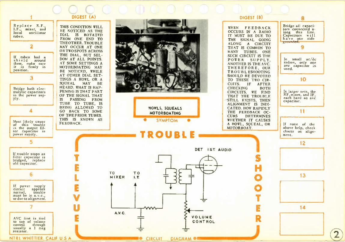
Replace R.F., I.F., mixer, and local oscillator tubes.
2
If tubes had a shield around them, make sure it is firmly in position.
3
Bridge both elec-trolytic capacitors in the power sup-ply.
4
Most likely cause of this trouble is the output fil-ter capacitor in power supply.
5
If trouble stops as filter capacitor is bridged, replace old capacitor.
6
If power supply circuit appears normal, trouble must be in a.v.c., or due to alignment.
7
AVC line is tied to top of volume control through usually a 1 meg resistor.
DIGEST 1A)
THIS CONDITION WILL BE NOTICED AS THE DIAL IS ROTATED FROM ONE END TO THE OTHER. TROUBLE MAY OCCUR AT ONE OR TWO SPOTS ACROSS THE DIAL, BUT SEL-DOM AT ALL POINTS. AT SOME SETTINGS A MOTORBOATING MAY BE NOTICED, WHILE AT OTHER DIAL SET-TINGS A HOWL OR A SQUEAL MAY BE HEARD. WHAT IS HAP-PENING IS THAT PART OF THE SIGNAL THAT IS PASSING FROM TUBE TO TUBE, IS BEING ALLOWED TO GO BACK TO SOME OF THE PRIOR TUBES THIS IS KNOWN AS FEEDBACK.
TO MIXER
V
HOWLS, SQUEALS
MOTOR BOATING
TO I F
A
A.V. C
• SYMPTOM •
DIGEST (B)
WHEN FEEDBACK OCCURS IN A RADIO IT MUST BE DUE TO THE SIGNAL GOING ALONG A CIRCUIT THAT IS COMMON TO MANY TUBES. ONE SUCH CIRCUIT IS THE POWER SUPPLY, ANOTHER IS THE AVC. THEREFORE, OUR TROUBLESHOOTING SHOULD BE DEVOTED TO THESE TWO CIR-CUITS. IF AFTER CHECKING BOTH CIRCUITS, WE FIND THAT THE TROUBLE
----STILL EXISTS, THEN ALIGNMENT IS INDI-CATED. HOW RAPIDLY THE FEEDBACK OC-CURS DETERMINES WHETHER IT CAUSES A HOWL, SQUEAL, OR MOTORBOAT.
TROUBLE
DET 1ST AUDIO
— F/VVVV- -
/4 V 0 LUN E CONTROL
0
8
Bridge all capaci-tors connected a-long this line. Capacitors will have one side
9
In small ac/dc radios, only one avc capacitor is used.
10
In larger sets, the RF, mixer, and IF, each have an avc capacitor.
11
If none of the above help, check charts on align-ment.
12
13
14
NTRL WHITTIER, CALIF U S A • CIRCUIT DIAGRAM •

1
Replace all tubes one at a time.
2
Check to see if speaker is causing the distortion by GENTLY applying pressure to cone.
3
If distortion clears as pressure is ap-plied, try substi-tute speaker.
4
If speaker appears normal, connect a signal generator with an audio tone, to grid of output tube.
5
If tone appears distorted (two tones are heard) then trouble is in output stage.
6
Check cathode re-sistor for a change in value, or cou-pling capacitor for being leaky at grid.
7
If cathode capacitor is used, check it for a short.
GEse, c IN ALMOST ALL CASES, DISTORTION IS CAUSED BY A CHANGE IN BIAS ON ONE OF THE TUBES. THIS MAY BE DUE TO A LEAKY COUPLING CAPACI-TOR, OR PERHAPS A SHORTED TUBE, HOW-EVER, IT WILL STILL UPSET THE BIAS ON THAT CIRCUIT. WITH THE WRONG BIAS, THE GRID WILL NOT CON-TROL THE ELECTRON FLOW TO THE PLATE CORRECTLY, AND DIS-TORTION WILL RE-SULT. THE PROBLEM IS TO FIND THE CIR-CUIT THAT IS CAUSING THE TROUBLE.
V
DISTORTION ON ALL STATIONS
I ST AUDIO
SYMPT OM •
TROUBLE
NTRL W HITTIER, CALIF U S A • CIRCuii IL IMII M MI MIIIIIIII III
=.
AUDIO OUTPUT
B +-
DIAGRAM •111 M MII MMII MIN .1111 M110 )
DIGtof (B)
ONE OF THE THINGS TO DO WITH DIS-TORTION, IS TO TRY AND ISOLATE THE TROUBLE TO THE DEFECTIVE STAGE AS QUICKLY AS POSSIBLE, AND THE SIGNAL GEN-ERATOR CAN BE A GREAT HELP IN DOING THIS. HOWEVER, IF YOU DO NOT PLAN ON USING A GENERATOR THEN FOLLOW THE STEPS BELOW CHECK-ING THE PARTS AS INDICATED. IF THIS DOES NOT CLEAR THE DISTORTION, THEN MOVE ON TO THE NEXT STEP. KEEP IN MIND THAT WE ARE LOOK-ING FOR A TROUBLE THAT IS UPSETTING THE BIAS.
0
If tone is normal at output grid, move generator to grid of 1st audio. Feed in an audio signal.
9
If tone is distorted, check value of grid resistor and plate resistor.Also check for leaky coupling capacitor.
10
The above circuits are the most common causes of distortion, however, complete loss of avc can also cause rhi c
11
Measure voltage on avc line. ShoWd be -2v to -5v. If zero, then avc line is shorted.
12
If trouble is in avc, then disconnect each avc capacitor, if dis-tortion clears, replace that capacitor.
13
If avc line normal, then check bias on each of the following. RF, IF, mixer.

1 Replace all of the tubes one at a time.
2
Connect meter on avc line. Should be negative volts.
3
Vary dial from one station to the next. Reading should vary.
4
With this trouble, reading will prob-ably vary a small amount, or not at all.
5
If voltage zero, suspect a shorted avc capacitor. Disconnect it to check.
6
If voltage low, about I volt, sus-pect a short or leak in one of the avc capacitors.
7
Take resistance check along avc line, looking for low resistance or short to ground.
DIGEST (A)
DISTORTION ON SOME STATIONS, AND NOR-MAL OPERATION OF OTHERS, IS AN INDICA-TION THAT THE TROU-BLE MUST BE IN THE AVC SYSTEM. SINCE THE AVC CONTROLS THE STRENGTH OF THE SIGNAL PASSING TO THE DETECTOR, THEN IT MUST NOT BE DOING ITS JOB IF IT ALLOWS SOME OF THE STATIONS TO DISTORT. THE FACT THAT SOME STATIONS ARE COMING IN NOR-MALLY, WOULD TELL US THAT THE AUDIO SYSTEM IS IN WORKING CONDITION, SINCE IF IT WERE BAD, ALL STATIONS WOULD DIS-TORT.
V
DISTORTION ON S°M iE STATIONS
• SYMPT OM •
TROUBLE
MI XER IF A tIM M 11 . 71
DI GEST (B)
DISTORTION IS DUE TO A CHANGE IN BIAS OF AN AMPLIFIER, AND INSTEAD OF OPERATING AT THE CORRECT POINT ON THE Eglp CURVE, IT IS OPERATING TOO FAR UP OR DOWN. THE AVC CONTROLS THE BIAS ON THE IF AMP, MIXER, AND RF AMP. IF THERE IS NO AVC, THESE TUBES WILL AMPLIFY STRONG SIGNALS TOO MUCH, WITH THE RE-SULT OF DISTORTION DUE TO THE LARGE SIGNAL BEING AP-PLIED TO ONE OR MORE OF THE TUBES.
A.V.C. LI NE AF
0
LIMBI NIBINMINI MNIMI U S A MEMENIMIIIM MINI IIII ) • CIRCUIT DIAGRAM •
8 Trouble may be due to leakage from primary to secondary of IF transformer.
9
To check this unsolder all lead; from secondary of IF transformer.
10
Now with set switched on, meas-ure voltage from disconnected leads to ground.
11
If a voltage is present, say 50v, then transformer is defective.
12
When replacing IF transformer, be sure to get correct one. I st IF or 2nd.
13
If trouble still present check for change in cathode resistor in IF or RF amps.
14
NT R L W HITTIER, CALIF

Replace all tubes. In particular the audio output tube.
2
If trouble still present, connect meter on low volts scale to grid of output tube.
3
With set operating normally, the grid should have zero volts.
4
If grid has some positive voltage, and the tube has been replaced, sus-pect grid capacitor.
5
Remove old capa-citor and place new one in circuit, this should cure trou-ble.
6
If bias on output is normal, check bias on 1st audio amp.
7
This tube should have about -1v on the the cgartihdo, dez.e ro on
WHENEVER TIME IS INVOLVED IN A TROU-BLE, IT USUALLY ME ANSTUBE FAILURE UNDER HEAT VARIA-TIONS. IT IS POSSIBLE TO HAVE COMPONENT PARTS CHANGE WITH TIME, BUT THIS IS DUE TO HEAT FROM NEARBY PARTS SUCH AS VACUUM TUBES OR A WIRE WOUND DROP-PING RESISTOR. IN THIS CHART WE ARE REFERING TO A SET THAT PLAYS WELL FOR A FEW MINUTES, THEN SLOWLY, BEGINS TO DISTORT.
V
DISTORTION WHEN
SET WARMS UP
• SYMPT O M •
TROUBLE
NTRL W HITTIER, CALIF U S A L 1111=11111IIMMINII• CIRCUIT
Oft •••
*IP
B
HEAT, CAUSING MET-ALS TO EXPAND, CAN MAKE A TUBE HAVE LEAKAGE OR EVEN SHORT. MOST LIKELY CULPRIT IS THE AUDIO OUTPUT TUBE BECAUSE THIS TUBE USUALLY HAS THE MOST CUR RENT FLOW, GREATEST POWER OUTPUT, AND HIGH-EST OPERATING VOLTAGES. WHAT HAPPENS INTERNAL-LY, IS THAT THE CONTROL GRID HAS LEAKAGE TO THE CATHODE, OR SCREEN GRID. IF THE TUBES DO NOT CURE THIS TROUBLE, THEN CHECKS ON THE BIAS OF EACH TUBE MUST BE MADE.
0
DIAGRAM •IIIMMINNI IIIIIIIII J
If grid voltage n incorrect, check grid resistor and coupling capacitor.
9
With normal bias on 1st audio, check avc line voltage.
10
Avc should vary between —2v to —5v depending on the station.
11
If avc bias is low, or zero after set warms up, suspect defective avc capacitor.
12
Disconnect one capacitor at a time in the avc line until voltage jumps to normal.
13
14

1 Replace all audio tubes.
2
Check amount of bias on audio out-put tube.
3
For an AC set 10v to 15v. This will be measured on cathode.
4
For AC/DC set 5v to 8v. Also meas-ured on the cath-ode to common negative.
5
For a 3 way porta-ble, about 6v. This is measured be-tween grid, and filament of output tube.
6
If bias on audio output seems nor-mal check bias on 1st audio.
7
In all types of receivers, this bias is the same, about -1v.
DIGEST (A)
THIS TYPE OF A TROUBLE IS LIMITED TO THE AUDIO CIR-CUITS. THE REASON FOR THIS, IS THAT IF THE TROUBLE WERE CAUSED BY ANY CIR-CUIT IN THE IF RF STAGES, IT WOULD CAUSE THE DISTOR-TION TO APPEAR REGARDLESS OF THE SETTING OF THE VOLUME CONTROL. THIS MUST MEAN THAT THE TROUBLE IS EITHER IN THE 1ST AUDIO CIRCUIT, OR THE AUDIO OUTPUT STAGE. A VOLTAGE CHECK SHOULD SHOW UP THE TROUBLE.
V
IL I MMINI MIN IIIIIIII11111•111
—
NTRL WHITTIER, CALIF U S A CIRCUIT
DISTORTION AS VOLUME
CONTROL INCREASED
• SYMPTOM •
moor ilmor TROUBLE
NOP
DIAGRAM •
DIGEST (B)
WHAT IS HAPPENING IN THIS TROUBLE, IS THAT THE BIAS OF ONE OF THE AUDIO TUBES MUST BE OFF A LITTLE. THIS WOULD ACCOUNT FOR NORMAL OPERATION AT LOW VOLUME SET-TINGS, AND DISTOR-TION AS THE VOLUME CONTROL IS TURNED UP, AND THE INPUT SIGNAL TO THE AUDIO AMPS GETS LARGER. IF IT IS NOTICED THAT AT HIGH VOL-UME CONTROL SET-TINGS THE SET STOPS PLAYING, WE CAN SUSPECT THE COU-PLING CAPACITOR FROM THE VOLUME CONTROL TO GRID OF 1ST AUDIO.
V
B +
0
8
Vary volume con-trol to see if it changes the bias.
9
If it does, then suspect the cou-pling capacitor from volume con-trol to 1st audio grid.
10
If volume control has no effect on 1st audio bias, but bias is wrong val-ue,, check grid resistor.
11
If bias seems con-stant, and of the right value, check prate load resistor.
12
If plate load in-creases, it will drop plate voltage too far, and will distort on large signal.
13
14

Replace all tubes.
2
Measure B plus voltage. AC= 250v. AC/DC= 90v.
3
If B plus low, bridge filter capacitors in power supply.
4
With normal B plus, connect audio gen to grid of audio output tube.
5
With maximum out-put, tone should be loud. If weak, sub-stitute speaker, bridge cathode capacitor.
6 at grt,
move gen to 1st audio grid. Should hear VERY loud tone.
7
If weak tone, check plate resistor for decrease, bridge coupling capacitor to audio output grid.
GES C)
THE VOLUME CON-TROL IN MOST RADIOS WILL INCREASE THE VOLUME OF SOUND TO A POINT WHERE IT IS JUST TOO LOUD TO LISTEN TO. IF THE VOLUME CONTROL IS TURNED ALL OF THE WAY UP, AND THE SOUND IS STILL BE-LOW NORMAL LISTEN-ING LEVEL, THEN THE RADIO HAS A CONDI-TION OF WEAK SOUND. THIS TYPE OF A TROUBLE CAN BE CAUSED BY ALMOST ANY PART OF THE RADIO, AND SHOULD BE LOCALIZED TO A CERTAIN STAGE AS SOON AS POSSIBLE.
NTR I W HITTIER. CALIF U S A
WEAK SOUND
• SYMPT O M •
TROUBLE
V
1.4 I XER
TUBES AND LOW POW-ER SUPPLY VOLTAGE ARE THE MOST COM-MON CAUSES OF THIS TROUBLE. HOWEVER, SUCH THINGS AS AN OPEN CATHODE CA-PACITOR ACROSS THE AUDIO OUTPUT TUBE CATHODE, AND A DE-CREASE IN VALUE OF A COUPLING CAPACI-TOR, MAY ALSO CAUSE THIS CONDITION. BY FEEDING IN A SIGNAL FROM A GENERATOR, WE CAN USUALLY DE-TERMINE THE STAGE THAT IS AT FAULT. ONCE THE STAGE HAS BEEN FOUND, THEN A FEW VOLTAGE CHECKS AND COMPON-ENT SUBSTITUTIONS WILL LOCATE THE TROUBLE.
AUDIO
OUTPUT
0
INII II MMIIIMI 111 ) CIRCUIT DIAGRAM •
8 Connect gen to tap of volume contra, control fully on. Should hear VERY loud tone.
9
If weak, bridge coupling capacitor from volume con-trol to 1st audio grid.
10
If ok at volume control, feed in mod IF signal to IF amp grid. Should hear loud tone.
11
If weak, check cathode resistor, and detector re-sistance. Include volume control.
12
If tone still weak, try adjusting IF transformer, then replace trans-former.
13
Use same pro-cedure on mixer grid, if weak at this point, try IF align-ment.
14
If normal tone at mixer, then trouble must be in RF amp (if used), or antenna.

1 ep ace all tubes one at a time. If rectifier is bad, and new one also burns out, refer to chart on that trouble.
2 I It tubes do not help, I remove and reinsert audio output tube quickly, a double click should be heard.
Do on
not use step #2 3 way portable
receivers. You may damage filaments.
4
If there is no click, measure voltage of power supply and audio output.
5
If there is no voltage from power supply, then troubleshoot that circuit.
6
With no plate voltage, suspect an open tin ns former or shorted tone capacitor.
7
If cathode voltage measures high, sus-pect an open cathode resistor.
DIGEST •(A)
MOST COMMON TROU-BLE IN A RADIO, AND AN ATTEMPT SHOULD BE MADE TO ISOLATE THE CAUSE OF THE TROUBLE TO EITHER THE AUDIO CIRCUITS, OR THE IF RF CIR-CUITS. ONCE ISOLAT-ED, THE DEFECTIVE CIRCUIT CAN BE FOUND BY MEANS OF A GENERATOR, AND FINALLY A VOLTAGE CHECK WILL INDICATE THE DEFECTIVE COM-PONENT. IF A GEN-ERATOR IS NOT GOING TO BE USED FOR THIS, THEN ONCE THE TROUBLE IS ISOLATED TO EITHER THE AUDIO OR IF RF, VOLTAGE CHECKS SHOULD BE MADE AS INDICATED. IN THIS CHART WE AS-SUME TROUBLE TO BE IN THE AUDIO STAGES.
NO SOUND
V
VOLUME CONTRO L
• SYMPTOM •
TROUBLE
AUDIO OUTPUT
B
DIGEST (B) 8 THERE ARE CERTAIN CHECKS THAT CAN BE MADE ON A RADIO, THAT WILL TELL IF SECTIONS ARE, OR ARE NOT, WORKING. FOR EXAMPLE, BY SIMPLY REMOVING AND REINSERTING QUICKLY, THE AUDIO OUTPUT TUBE, WE SHOULD HEAR A DOU-BLE CLICK IN THE SPEAKER. THIS WILL TELL US THAT THE POWER SUPPLY, SPEAKER, AND OUT-PUTCIRCUIT ARE ALL WORKING. ONE THING TO KEEP IN MIND HOWEVER, IS THAT THIS STEP MUST NOT BE USED ON 3 WAY PORTABLES, AS WE MAY DAMAGE ONE OR MORE OF THE TUBE HEATERS BY REMOV-ING ONE OF THE TUBEc.
If voltages are nor-' mal try a substitute speaker. Also check I output transformer secondary for an open.
0
B +
II IIIII MI I )DIAGRAM • _
9
If a click is heard as output tube is re-moved, then turn vol-ume full on and touch center tap of control.
10
A buzz should be I heard in the speaker ' as control is touched with finger.
11
If there is no buzz, then touch grid of 1st ' audio amp. If buzz now, check capacitor at center tap of con-
12
' If no buzz as grid is touched, then take voltage check of 1st audio.
13
1 If, as you touch cen-i ter of volume control i a buzz is heard, then J entire audio is okay.
14
Check volume control for an open. If okay, then use next chart on No Sound.
NTRL WHITTIER, CALIF U S A • CIRCUIT

Be sure that all tubes have been changed first.
2
Connect a signal generator to the grid of the IF amp. If tone heard, IF and detector O.K.
3
If no tone, take voltage check of IF amp. If normal take resistance check of detector.
4
If all appear nor-mal, adjust IF transformer. If this doesn't help, re-place transformer.
5
If tone is heard at IF, move gen back to grid ol mixer. Be sure you are at mixer grid.
6
Feed in an IF sisnal at mixer grid. Should hear a tone in speaker.
7
If no tone, take voltage checks of mixer tube. If voltage normal, take resistance check.
IN THIS CHART, WE ARE ASSUMING THAT THE PRELIMINARY CHECKS HAVE BEEN MADE, AND THAT THE CENTER TAP OF THE VOLUME CONTROL HAS BEEN TOUCHED, AND A BUZZ IS PRES-ENT. IF THERE WERE NO BUZZ, THEN RE-FER TO THE PRE-VIOUS CHART ON NO SOUND. SINCE WE NOW KNOW THAT THE TROUBLE IS IN THE RF IF CIRCUITS, IT WILL BE AN ADVAN-TAGE TO FIND OUT WHICH CIRCUIT IS AT FAULT. A SIGNAL GENERATOR SHOULD NOW BE USED.
NO SOUND
r.111.1. MI MI M MI.MOD I.F
OR R.F.
V
V
TO OSC
• SYMPT O M •
TROUBLE
MIXER
B
NTR I w HiTTIER, CALIF U S A • CIRCUIT
I.F. A MP
B
A.V.C.
(B)
IF THE IF AMPLIFIER AND THE DETECTOR CIRCUITS ARE WORK-ING, THEN A TONE SHOULD BE HEARD IF WE FEED IN A MODULATED (VARIED WITH AUDIO) CARRIER SIGNAL AT THE IF OF THE SET. IN ALMOST ALL SETS, THIS IS AT 455KC. IF WE DO NOT HEAR THE TONE, THEN WE WOULD KNOW THAT EITHER THE IF, OR THE DETECTOR IS AT FAULT. BY US-ING THE SAME PRIN-CIPLES, BUT DIFFER-ENT FREQUENCIES, WE CAN DETERMINE IF THE OSCILLATOR OR THE RF AMPLIFIER (IF USED)IS AT FAULT.
0
DIAGRAM ••• =11111 =I M MIIIIIIIM MI )
If a tone is heard, then mixer is okay but oscillator may be defective.
9
oc cc osc, ee in a tone at 1000kc. Set radio dial to same frequency (1000kc).
10
If a tone is heard, then oscillator is working. You may have to move gen dial back and forth a few kc.
11
If no tone, check osc coil for an open, if ok, check grid resistor. Replace grid capacitor.
12
If osc is working, check loop antenna for a break, or if an RF amp is used, check below.
13
Go to grid of RF amp feed in a 1000kc modulated signal. Set radio dial to 1000kc.
14
If no tone, take voltage and resist-ance checks of RF amp. If tone heard, check antenna to set.

Make sure that tubes are in their right sockets.
2
Check each tube for an open fila-ment.
3
If rectifier fila-ment is open,check for a short in B plus line before replacing tube.
4
If tubes okay check on/of? switch to see if it makes and breaks contact.
5
If switch is bad, it may be neces-sary to replace volume control as well.
6
With switch okay, check line cord for break.
7
Most common point for line cord to break is at ac plug, or where line enters set.
DIGEST (A)
IF NONE OF THE TUBES LIGHT IN AN AC/DC RECEIVER, THE TROUBLE MUST BE DUE TO EITHER A DEFECTIVE TUBE, A BREAK IN THE LINE CORD, OR A BAD ON OFF SWITCH. ALL OF THESE CAN BE CHECKED WITH AN OHMMETER. ANOTHER COMMON METHOD OF CHECKING FOR A BREAK IN THE AC LINE, IS TO PLACE A METER, ON AC VOLTS, ACROSS EACH ONE OF THE TUBES AND ON/OFF SWITCH. WHERE THE BREAK IS, YOU WILL MEASURE FULL AC LINE VOLT-AGE.
V
TUBES DO NOT LIGHT
• SYMPT OM •
TROUBL
128E6
35 W4 5005 I2BA6 12AV6
4
Lii m mi m muno
DIGEST (B)
IN SOME CASES, ALL TUBES ARE GOOD, BUT SOMEONE HAS PUT THEM IN THE WRONG SOCKETS. THIS WILL BREAK THE CONTINUITY OF THE LINE, AND NONE OF TUBES WILL LIGHT BECAUSE IN AC/DC RECEIVERS THE TUBES ARE IN SERIES. THERE IS THE RARE POSSIBILITY THAT A BREAK HAS OCCURED IN THE WIRING OF THE FILAMENTS, BUT THIS IS NOT COMMON. IN SOME OF THE NEW SETS, WITH PRINTED CIRCUIT BOARD, POOR SOLDERING COULD OCCUR TO BREAK THE FILAMENT LINE.
0
DIAGRAM ••_ 1 1_1• 11.111 1 )
8 If receiver is a clock radio, make sure that clock control is in the on position.
9
Be sure that clock plug is in socket on radio chassis. If out, it will break filament line.
10
If all appear nor-mal, take ohmmeter and follow line from plug through switch to filaments.
11
Trouble must be in filament line.
12
13
14
NTRL W HITTIER, CALIF U S A CIRCUIT

Replace the con-verter tube.
2
Make sure that the dial shaft is ro-tating the tuning capacitors.
3
Check tuning capacitors for a broken lead. 1
4
Check for a short in tuning capaci-tors. This can be done visually, or as follows:
5 Unsolder all leads from tuning capaci-tor. Ground casing, and applya voltage to terminal not grounded.
6 Fully open tuning capacitor, then slowly mesh plates. If plates arc, then they are shorted.
7
If tuning capacitor appears okay, then trouble must be in oscillator circuit.
GES C
WHEN THE DIAL IS ROTATED FROM ONE END TO THE OTHER, AND ONLY ONE STA-TION IS PRESENT ALL OVER THE DIAL, IT INDICATES THAT THE OSCILLATOR CIRCUIT IS DEFECTIVE. THIS MUST BE SO SINCE THE OSCILLATOR IS SUPPOSED TO CHANGE FREQUENCY AS THE DIAL IS VARIED, SO THAT IT CAN PRO-DUCE THE IF AS DIF-FERENT STATIONS ARE DESIRED. WHEN THE OSCILLATOR STOPS, THE CIRCUIT MAY START TO OSCIL-LATE AT ONE FRE-QUENCY REGARDLESS OF POSITION OF RA-DIO DIAL, AND ONLY ONE STATION WILL PASS.
ONLY ONE STATION
ON DIAL
NTRL W HITTIER, CALIF U S
V
LO OP
ANTENNA
111
• SYMPT O M •
ANOTHER CAUSE OF ONLY ONE STATION ALL OVER THE DIAL, IS TIRE TUNING CA-PACITOR, IF FOR SMIF. REASON IT BE-C A' I E DISCONNECTED, OR THE DIAL SHAFT DID NOT ROTATE THE MAIN TUNING ASSEM-BLY, THEN ONLY ONE STATION WOULD BE PRESENT. IN MOST CASES HOWEVER, THE TROUBLE IS IN THE OSCILLATOR CIRCUIT.
TROUBLE
)1(1)1(
A GAN GED
• CIRCUIT DIAGRAM •I•1111 1111 M1
0
8 Take resistance check of osc coil and grid resistor. Bridge all capaci-tors.
9
Check wiring of circuit. Sometimes someone has re-wired circuit.
10 If circuit uses a padder adjustment, it may be shorted. Disconnect and check.
11
Replace oscillator coil.
12
13
14

1 Replace the con-verter tube. If a separate osc tube is used, replace it.
2
Check for normal B plus.
3
AC = 250v. AC/DC = 90v. 3 Way = 90v. Auto radio = 200v.
4
Readings should be within 10% ex-cept 3 Way radio. If low replace rectifier.
5
Check tuning capacitor plates for excessive dirt or shorted plates.
6
If very dirty, use air compressor at gas station to blow out dirt.
7
If still dirty, re-move tuning capa-citor and soak in carbon tetrachlo-ride for an hour or more.
DIGEST (A)
WHEN A RECEIVER OPERATES ACROSS ONLY PART OF THE TUNING BAND, IT IS DUE TO EITHER A CRITICAL OSCILLA-TOR CIRCUIT, OR TO DIRT AND DUST IN THE MAIN TUNING CA-PACITOR, PERHAPS ONE OF THE PLATES IS TOUCHING ANOTH-ER AT SOME POINT ON THE TUNING RANGE. HOWEVER, THE TROUBLE IS LIMITED TO THE OSCILLATOR, MIXER, RF CIRCUITS, SINCE THE FACT THAT ONE SIGNAL IS PASSING THROUGH THE IF, DET, AND AUDIO STAGES MEANS THAT THEY ARE WORKING OKAY.
NTRL WHITTIER, CALIF U S A
T E L E V U E
LOOP
ANTENNA
I SET PLAYS ON HALF OF DIAL I
/ A.V. C. i
/ tommi m G A NGE 0
• CIRCUIT
/
-1--t-• i
• SYMPTOM •
DIGEST (B)
ALL OSCILLATOR CIR-CUITS ARE FAIRLY CRITICAL. THAT IS, THEY OPERATE BET-TER AT HIGHER FREQUENCIES THAN AT LOWER FREQUEN-CIES UP TO A POINT. WE FIND THAT THE AMOUNT OF BIAS THE OSCILLATOR HAS, INCREASES AS THE FREQUENCY INCREAS-ES, AND THIS MAKES THE CIRCUIT MORE EFFICIENT. FAILURE OF THE OSCILLATOR MAY BE DUE TO SLIGHTLY LOWERED B PLUS, ESPECIALLY IF IT IS A 3 WAY PORTABLE.
TROUBLE A 0-7 ----)
CON V ERTER
i
I T
•
1 B +
I S H 0 0 T E R
11 111•11111 =1 •11111M MI ) DIAGRAM •
8 If tuning cap ok, check value of oscillator grid resistor.
9
Replace grid capacitor. U s e same value as one in the set.
10
Oscillator may be out of alignment. Check chart on RF alignment.
11
If set will not align at one end of dial replace oscillator coil.
12
13
14

See if any of the tuning plates are touching. Outside ones are the likely ones.
2
Sometimes it helps if a piece of white paper is placed under the plates.
3
If plates appear dirty, try to clean with rag or paint brush.
4
May have to remove capacitor and take to gas station tc use air compressor.
5
Do not use air compressor while capacitor in set, it may damage parts due to force.
6
If blowing out dirt doesn't help, soak overnight in car-bon tetrachloride.
7
Do not use tetra-chloride in a closed room, fumes are dangerous.
""'"'
C
WHEN A SCRAPING SOUND IS NOTICED AS THE DIAL IS ROTATED, IT IS USUALLY DUE TO DUST AND DIRT IN THE TUNING CA-PACITOR, OR TO PLATES THAT ARE TOUCHING AS THE TUNING CAPACITOR IS VARIED. ONCE IN A WHILE IT WAS FOUND THAT THE TROUBLE WAS DUE TO A DIRTY TUNING SHAFT EITHER DIRECTLY CONNECT-ED TO THE TUNING CAPACITOR, OR TO A DIAL STRING ARRANG-MENT.
NTRL W HITTIER, CALIF U 5 A
V
Fr SCRAPING SOUND
AS DIAL MOVES
• SYMPT O M •
TROUBLE
- - - - - - AN D
•
CONVERTER
CIRCUIT DIAGRAM •
SOME OF THE OLDER RADIO RECEIVERS HAD TUNING CAPACI-TORS THAT USED PLATES VERY CLOSE TOGETHER. THESE ARE VERY LIKELY TO CAUSE THIS TROUBLE BECAUSE OF DIRT BUILDUP OVER THE YEARS. IF THE TROU-BLE IS FOUND IN A FAIRLY MODERN RE-CEIVER, THEN THE CHANCES ARE THAT IT IS DUE TO PLATES TOUCHING EACH OTH-ER. VARIOUS METHODS ARE DISCUSSED HERE AS TO REMOVING THESE TROUBLES.
B-4--
S0
8 - If short is not apparent, unsolder tuning capacitor, and remove from set.
9
Connect about 50v ac or dc across one section. From one lug to chassis of cap.
10
Rotate plates and observe closely where arcing is occuring.
11
Use thin bladed screwdriver to straighten plates.
12
If arcing in many areas, may be better to replace capacitor.
13
If tuning cap ap-pears ok, place a few drops of thin oil on all shafts.
14
Great care must be taken to avoid getting oil on dial string, if used.

1 See if all stations are off by the same amount.
2
If they are, trou-ble may be dial pointer out of position.
3
Move dial from one end to the other, if pointer won't go all the way, adjust it.
4
If pointer set okay, but stations still off, try oscillator adjustment as fol-lows.
5
Set dial to a known station at high end of dial around 1 200kc.
6
Adjust oscillator trimmer until known station is present. This may do it.
i 7
If stations still at wrong point along dial, refer to R.F. alignment chart.
DIGEST (A) •
WHEN THE STATIONS DO NOT COME IN AT THE RIGHT POINTS ON THE DIAL, IT MAY BE DUE TO ALIGN-MENT, INCORRECT DIAL POINTER SET-TING, OR INCORRECT-LY SPACED TUNING PLATES. AS FOR ALIGNMENT, YOU WILL PROBABLY NOTICE THAT THE LOWER FREQUENCY STA-TIONS COME IN CLOS-ER TO THEIR COR-RECT POINT THAN THE UPPER FREQUEN-CY STATIONS. THIS IS DUE TO THE MORE CRITICAL ADJUST-MENTS THAT MUST BE MADE AT THE HIGH FREQUENCY END OF THE DIAL.
NTRI W HITTIER, CALIF U S A
T E L E V U E
I STATIONS AT WRONG POINT ON DIAL I
/ i GANGED
/
• SYMPT OM •
DIGEST (B)
IF THE DIAL POINTER IS OFF OF ADJUST-MENT, THEN ALL STATIONS WILL BE OFF BY THE SAME AMOUNT. THE THING TO LOOK FOR, IS IF THE POINTER TRAV-ELS ALL THE WAY FROM ONE END TO THE OTHER. THIS WOULD BE A CLUE AS TO THE POSSIBILITY OF THE POINTER BE-ING SET WRONG. SOME-TIMES THE PLATES OF THE TUNING CA-PACITOR ARE MOVED APART, AND AL-THOUGH TRACKING AT ONE END OF THE DIALMAY BE NORMAL, IT WILL BE OFF AT THE OTHER END.
TROUBLE
S H 0 0 T
THIS TRIMMER
MAY NE ED
ADJU STIN G
E R
0 CIRCUIT DIAGRAM •• 111.11. ...11111.0111 M J
8 If aligning does not help, then tuning plates may be set wrong.
9 Check plates care-fully to see if they are out of line, or bent.
10
Use ruler to re-adjust plates. Get them evenly spaced.
11
After adjusting plate spacing, realign radio.
12
13
14

Replace all tubes one at a time. Allow time for trouble to develop.
2
When set stops, apply pressure to speaker. Cone may stick.
3
Check B plus. If off more than 10%, try bridging filter capacitors.
4
In the 3 way porta-ble, B plus must be almost perfect, 90 volts.
5
Take visual check, while applying slight pressure to components.
6
If set goes on and off as pressure applied, check parts close by.
7
If set plays nor-mally for a long time, throw blan-ket over set, or place in box.
--c•AGES C)
AN INTERMITTENT RADIO CAN KEEP THE SERVICEMAN BUSY FOR A LONG TIME UNLESS A DEFINITE PROCEDURE IS USED. ONE MUST KEEP IN MIND THAT ANY PART OF THE RADIO CAN CAUSE THIS KIND OF A TROUBLE, THAT IS WHY IT MUST BE LOCALIZED AS SOON AS POSSIBLE. BEFORE USING ANY EQUIP-MENT HOWEVER, A CHECK SHOULD BE MADE ON THE TUBES, SPEAKER, AND IF COILS. ALSO A VISUAL INSPECTION INCLUD-ING PRESSURE AP-PLIED TO COMPON-ENTS UNDERNEATH CHASSIS.
NTRL W HITTIER, CALIF U S A
V
• SYMPT OM •
TROUBLE
SPEAKER CONE
MAY BE STICKING
DIGEST (B)
USING A SIGNAL GENERATOR WILL PINPOINT THE TROU-BLE TO ONE OF THE STAGES, AND THEN COMPONENT SUBSTI-TUTION, AND RESOLD-ERING, ESPECIALLY ON A PRINTED BOARD, WILL CURE THE TROUBLE. SOME SETS WILL PLAY FOR DAYS WITHOUT STOP-PING, AND THEN MAY QUIT FOR A FEW MINUTES, AND BEFORE YOU HAVE TIME TO CHECK, THE SET PLAYS AGAIN. SUCH TROUBLES ARE BEST HANDLED BY THROW-ING A BLANKET OVER SET, AND GETTING IT TO HEAT UP FAST, THUS BRINGING TROU-BLE TO A HEAD.
0
LII II M MI MI. • CIRCUIT DIAGRAM • MI MI MI MINIU M MININ )
3
Sometimes taking a hot iron, and holding under parts, will bring on trouble.
9
If trouble per-sists, feed in audio signal to grid of output tube.
10
If there is no tone, troubleshoot out-put circuit. If tone, go to 1st audio grid.
11
If tone passes here, then move to grid of IF amp, feed in Mod IF signal.
12
Continue this method of checking each stage until bad stage found.
13
To check osc, go to grid of mixer, feed in 1000kc, and set radio dial to 1000kc.
14
If tone present, then osc ok. If no tone, then check osc circuit.
• 11,
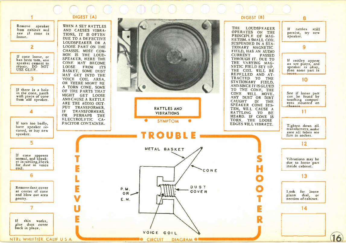
Remove speaker from cabinet and see if cone is loose.
2
If cone loose, or has been torn, use speaker cement to repair._ DO NOT USE GLUE.
3
If there is a hole in the cone, patch with piece of cone from old speaker.
4
If torn too badly, have speaker re-coned, or buy new speaker.
5
If cone appears normal, and speak-er is rattling,check for dust in voice coil.
6
Remove dust cover at center of cone and blow out area gently.
7
If this works, glue dust cover back in place.
DIGEST (A)
WHEN A SET RATTLES AND CAUSES VIBRA-TIONS, IT IS OFTEN DUE TO A DEFECTIVE LOUDSPEAKER OR A LOOSE PART ON THE CHASSIS. MOST COM-MON IS THE LOUD-SPEAKER, HERE THE CONE MAY BECOME LOOSE FROM ITS BASKET, SOME DUST MAY GET INTO THE VOICE COIL AREA, OR THERE MIGHT BE A TORN CONE. SOME OF THE PARTS THAT MIGHT GET LOOSE AND CAUSE A RATTLE ARE THE AUDIO OUT-PUT TRANSFORMER, IF TRANSFORMERS, OR PERHAPS THE ELECTROLYTIC CA-PACITOR CONTAINER.
NTRL WHITTIER, CALIF U S A
V
RATTLES AND VIBRATIONS
P. M.
OR
E. M.
• SYMPTOM •
TROUBLE METAL BASKET
CO N E
DU S T
COVE R
VOIC E COI L
DIGEST (B)
THE LOUDSPEAKER OPERATES ON THE PRINCIPLE OF MAG-NETISM. A SMALL COIL SUSPENDED IN A STA-TIONARY MAGNETIC FIELD, HAS AN AUDIO CURRENT PASSED THROUGH IT. DUE TO THE VARYING MAG-NETIC FIELD SET UP, THE COIL WILL BE REPELLED AND AT-TRACTED TO THE STATIONARY FIELD, AND SINCE IT IS GLUED TO THE CONE, THE CONE WILL MOVE. ANY DUST OR DIRT CAUGHT IN THE SPEAKER CONE SYS-TEM, WILL CAUSE A RATTLING TO BE HEARD. IF CONE IS TORN, THE LOOSE EDGES WILL VIBRATE.
0
• CIRCUIT DIAGRAM •I MIII IIIMIIIIIII MI N )
8
If rattles still persist, try new speaker.
9
If rattles appear as set plays, and speaker is okay, then some part is
10
See if loose part can be found by touching compon-ents mounted on
11
Tighten down all transformers, make sure all tubes are firm in socket.
12
Vibrations may be due to loose part inside cabinet.
13
Look for loose glass dial, or section of cabinet.
14

I
Fireplace tubes one at a time. Wait to see if trouble oc-curs before re-placing next tube.
2
Take visual check of set. Look for loose part, or poor soldering.
3
Turn down volume control. If noise continues, trouble must be in audio circuits.
4
If noise stops as volume control turned down, trou-ble is in IFs or RF circuit.
5
If trouble in audio, short grid of out-put tube to com-mon negative.
6
If noise continues, then trouble in out-put circuit. Check parts. Replace out-put transformer:
7
If trouble in IF or RF, measure avc voltage, if zero or positive, suspect IF transformer.
NOISY OPERATION OF A RADIO IS OFTEN DUE TO A BREAKDOWN INSIDE ONE OF THE IF CANS. THIS IS USUALLY AN INTER-MITTENT CONDITION, WHERE SEVERE CRACKLING OCCURS FOR A PERIOD OF TIME, THEN NORMAL OPERATION. DURING THE NOISE PERIOD, THE RADIO STATION MAY NOT BE HEARD. IF THE VOLUME CON-TROL IS TURNED DOWN, AND THE NOISE FADES AWAY, IT ONCE AGAIN POINTS TO A DEFECT IN THE IFS.
V
NOISY OPERATION
• SYMPT OM •
TROUBLE
I. F. AMP
UNSOLDER
HERE
(6)
IF THERE IS AN INTER-MITTENT SHORT BE-TWEEN PRIMARY AND SECONDARY OF THE IF TRANSFORMER, IT WILL PLACE A POSI-TIVE VOLTAGE ON THE AVC LINE, THIS WILL PRODUCE A CRACKLE IN THE RECEIVER.OF COURSE OTHER COMPONENTS CAN CAUSE NOISY OPERATION, SUCH AS TUBES, POOR CON-TACT, CAPACITOR BREAKING DOWN, AND A DEFECTIVE RE-SISTOR. HOWEVER, AFTER A FEW QUICK CHECKS, THE POS-SIBILITY OF A BAD IF SHOULD BE LOOKED INTO BEFORE OTHER TROUBLES ARE CHECKED.
0
ILIO MII IIIII IIIMII INII I MIN =1111 111 ) NTRL W HITTIER, CALIF U S A - • CIRCUIT DIAGRAM •
3 Unsolder all con-nections from IF secondary of last IF.
9
Switch set on and measure voltage on disconnected secondary leads.
10
Voltage should be zero. If positive, then IF transformer is bad- Replace.
11
If IF transformer okay, repeat on 1st IF trans. Re-place if necessary.
12
If IFs appear okay, and avc is normal, place jumper from IF grid-to common neg.
13
If set still crack-les then trouble in IF amp circuit or detector.
14
Short out each grid in turn work-ing back to RF, until had stage isolated.

1 Remove rectifier and measure re-sistance from cathode pin to common neg.
2
Needle should indicate low resistance rising rapidly above 20,000 (Alms.
3
If zero, or low resistance (few hundred ohms) present, unsolder electrolytics.
4
Measure resist-ance again to see if short still pres-ent.
5
If short gone, then one of the elec-trolytics must be defective.
6
If short present, leave meter con-nected to cathode pin of rectifier.
7
Remove each tube one at a time. If short clears, then tube removed is bad.
DIGEST (A)
THE RECTIFIER CIR-CUIT OF A RADIO, SUPPLIES THE OPERA-TING VOLTAGES TO THE VARIOUS TUBES THAT ARE USED IN THE RECEIVER. IF THIS TUBE IS DEFEC-TIVE, AND ANOTHER ONE IS INSERTED, AND IT BURNS OUT, THEN SOME TROUBLE MUST EXIST EITHER IN THE RECTIFIER CIRCUIT ITSELF, OR IN THE CIRCUITS THAT IT FEEDS. USUALLY, A CHECK WITH THE OHMMETER WILL SHOW THE DE-FECTIVE SECTION.
RECTIFIER
KEEPS BURNING OUT
SYMPT OM •
r imimmlmomm TROUBL
V
RECTIFIER FILTER
CHOKE COIL
MAY BE
SHORTED
DI GEST (S)
TO AVOID POSSIBLE DAMAGE TO A NEW RECTIFIER TUBE, IT IS SUGGESTED THAT A RESISTANCE CHECK BE MADE FROM THE CATHODE PIN OF THE RECTIFIER, TO COM-MON NEGATIVE, WHEN-EVER A BAD RECTI-FIER TUBE IS FOUND IN ANY RADIO. IF A SHORT IS INDICATED ON OHMMETER, THEN A NEW TUBE HAS BEEN SAVED. NORMAL RESISTANCE FROM CATHODE TO COMMON NEGATIVE IS INDI-CATED WHEN METER NEEDLE JUMPS TO LOW RESISTANCE, THEN RISES RAPIDLY ABOVE 20,000 OHMS.
B + 0
8 If tubes are ok, unsolder any cir-cuit connected to B plus.
9
Start with lead going to plate of output tube.
10
Leave meter con-nected to rectifier cathode.. If short clears, check that circuit.
11
Continue to dis-connect each line on the B plus until short clears.
12
Common causes are: Output trans-former, IF trans-former. decoupling capacitors.
13
If normal reading in step #2, check filament line for a short.
14
Remember, it may have been a bad new tube, if all appear normal try another tube.
NTRL W HITTIER, CALIF U S A CIRCUIT DIAGRAM ONI MENIII

Switch off set and check for short internally with ohmmeter.
2
Look for short between heater and cathode.
3
Short most likely to be in 1st audio amp, or converter.
4
1st audio is usu-ally 12SQ7, or 12AV6.
5
Converter is usu-ally 12SA7, or 12BE6.
If all tubes appear okay, make sure they are in their right socket.
7
TFollow filament wiring, make sure they are wired correctly.
.GES, ,
WHEN SOME TUBES LIGHT AND OTHERS DO NOT IN AN AC/DC RECEIVER, THE TROU-BLE MUST BE DUE TO SOME SHORT IN THE FILAMENT LINE. MOST COMMON IN THIS TYPE OF TROUBLE, IS A HEATER TO CATHODE SHORT IN-SIDE ONE OF THE TUBES. THIS SHORTS OUT PART OF THE FILAMENT LINE, SINCE THE TUBES ARE ALL IN SERIES, AND SOME OF THE TUBES WILL NOT LIGHT. THE REMAIN-ING TUBES IN THE SET WILL BE OVER-HEATING DUE TO THE EXTRA VOLTAGE ON THEIR FILAMENTS.
NTRL W HITTIER, CALIF U S
SOME TUBES
DO NOT LIGHT
• SYMPT OM •
is TROUBLE
A L .
SHORTED
DIGt,“ (B)
IF THE TUBES USED ARE OF THE GLASS BULB TYPE, YOU WILL BE ABLE TO ACTUALLY SEE THAT SOME TUBES ARE NOT LIGHTING WHILE OTHERS ARE VERY BRIGHT. IN THE CASE OF ALL METAL BULB TUBES, A QUICK CHECK SHOULD AL-WAYS BE MADE BY TOUCHING THE TUBES TO SEE IF THEY ARE WARM. WITH A TROU-BLE OF THIS TYPE, SOME WILL BE COOL, WHILE OTHERS WILL BE VERY HOT.
0
MII II =IIIMENIIIII I CIRCUIT DIAGRAM •
8 Look for exces-sive solder on filament line wir-ing.
9
In a printed cir-cuit board look closely at printed wiring.
10
A long lead of a component on board may be cause of short.
11
Final possibility is a defective tube socket.
12
Check for this by removing tubes and checking socket for short.
13
14

1 Disable the local osc by placing jumper across osc tuning capacitor.
2
Connect signal generator to grid of IF amp. Feed in a mod IF signal.
3
Connect voltmeter from avc line to common neg on minus volt range.
4
Turn volume con-trol to convenient level.
5
Adjust output of generator so that meter reads about —2v.
6
Now adjust screws in last IF can for a maximum read-ing on meter.
7
At this point a turn of the screw left or right, will cause reading to decrease.
DIGEST (A)
CORRECT ALIGNMENT OF THE IF STAGES OF A RADIO RECEIVER CAN IMPROVE THE OVERALL OPERATION OF THE RADIO BY INCREASING THE SELECTIVITY AND SENSITIVITY OF THE RECEIVER. IMPROV-ING THE SELECTIVITY MEANS, TO BE ABLE TO REJECT ALL OF THE UNDESIRED SIG-NALS. INCREASING THE SENSITIVITY, IS TO HAVE MORE AMPLIFICATION, THUS ABLE TO HEAR WEAK-ER STATIONS BETTER.
V
• SYMPT OM •
TROUBLE
N,TRL W HITTIER, CALIF U S A .0. CIRCUIT
DIGEST (B)
WHEN ALIGNING THE IFS OF A RADIO, WE ARE SIMPLY ADJUST-ING THE IF TRANS-FORMERS SO THAT THEY WILL PASS THE CORRECT FREQUENCY WITH AS MUCH AMPLI-FICATION AS POSSI-BLE. ALIGNMENT CAN BE DONE BY EAR, OR BY EQUIPMENT, WHICH IS THE MORE ACCUR-ATE METHOD. DURING THE ALIGNMENT, THE LOCAL OSCILLATOR SHOULD BE DISABLED, SO THAT IT DOES NOT INTERFERE WITH THE READINGS. THIS IS BEST DONE BY PLACING A JUMPER ACROSS THE OSC TUN-ING CAPACITOR, FROM THE MOVING PLATES TO THE STATIONARY PLATES.
8
Move $en back to the grid of mixer.
9
Keep gen at mod IF, and adjust output so reading is about —2 v on meter.
10
Now adjust 1st IF screws for maximum on meter.
11
This should complete the IF alignment.
12
Remove jumper from osc tuning capacitor, and a lcontinuen m e tt R iFf
necessary.
13
If, after aligning IFs, set has a whistle or squeal check below.
14
Readjust all IF screws about one eighth turn each either way.

1 Connect signal gen to mixer grid. Feed in 1400kc mod signal.
2
Set radio dial to 1400kc. This must be set accurately.
3
Turn volume con-trol to a conven-ient level.
4
If a tone is not present, turn gen dial above and below 1400kc.
5
A loud tone should be present close to 1400kc.
6
Reset gen dial to 1400kc, and adjust osc trimmer on tuning cap until tone heard,
7
Be sure to adjust for loudest tone. Other weak tones may exist close by.
3ES )
ALIGNMENT OF THE RF CIRCUITS IN A RADIO RECEIVER, PROVIDES BETTER RECEPTION, AND MAKES POSSIBLE DESIRED STATION RECEPTION AT THE CORRECT POINT ON THE DIAL. THIS IS SOMETHING THAT YOU SHOULD CHECK BE-FORE A SET LEAVES THE SHOP. IT WILL MAKE THE CUSTOMER FEEL CONFIDENT IN YOU IF THE SET IS IN TIP TOP SHAPE, AND YOU WILL FEEL SATIS-FACTION IN A JOB WELL DONE.
V
tauNTRL WHITTIER, CALIF U S A • CIRCUIT DIAGRAM •
RF ALIGNMENT
• SYMPTOM •
Oil TROUBLE
00 KC
GL- ( B)
IN ORDER FOR A SET TO BE OPERATING CORRECTLY, THE LOCAL OSCILLATOR MUST BE OPERATING AT EXACTLY THE IF ABOVE THE INCOM-ING SIGNAL. THIS SHOULD HAPPEN WHEN THE DIAL IS SET TO THE DESIRED STATION. FOR THIS ALIGNMENT, WE WILL BE ADJUSTING THE TRIMMERS MOUNTED ON THE TUNING CA-PACITORS. SOME OF THE OLDER SETS AL-SO HAD A PADDER ADJUSTMENT FOR THE LOCAL OSCILLATOR. THIS WILL BE ADJUST-ED AT 600KC.
0
8
If set uses loop antenna, wrap 2 turns of wire a-round loop.
9
Connect gen to ends of wire, and feed in 1500kc mod signal. Set dial to 1500kc.
10
Adjust mixer trim-mer and RF trim-mer, if used, until maximum tone heard.
1 1
These trimmers are mounted on tuning capacitors.
12
If set has antenna terminal instead of loop, connect gen to antenna and ground.
13
If old set, may have osc padder. Feed in mod signal at 600kc to mixer grid.
14
Set dial to 600kc and adjust padder for maximum tone.

1 If set has fuse, check this first.
2
If fuse open, try another. If this blows, check chart #23.
3
If fuse ok, or no fuse used, check to see if rectifier lighting.
4
If it is, but all other tubes not lighting, suspect an open transform-er secondary.
5
Disconnect second-ary that feeds tube heaters. Check for open.
6
If rectifier doesn't light either, remove plug from wall socket.
7
Place ohmmeter a-cross on/off switch. See if it makes and breaks contact.
DIGEST (A) •
SINCE THE TUBES IN AN AC RECEIVER ARE CONNECTED IN PAR-ALLEL, THE FACT THAT NONE OF THEM LIGHT, WOULD JUST ABOUT ELIMINATE THE POSSIBILITY OF TUBE TROUBLE, SINCE IT IS MOST UN-LIKELY THAT ALL OF THE TUBES WENT BAD AT ONCE. WITH THIS THOUGHT IN MIND, OUR ATTENTION POINTS TO THE LINE CORD, ON/OFF SWITCH, OR POWER TRANSFORMER.
r mimmommimmi TROUBL
00-
V
} TO RECTIFIER FILAMENTS TO RECTIFIER PLATES TO OTHER TUBE HEATERS
DIGEST (B) THE AC RECEIVER TAKES THE 117 VOLT INPUT, AND APPLIES IT TO A POWER TRANSFORMER. THE TRANSFORMER STEPS THIS VOLTAGE UP AND DOWN. UP FOR THE POWER SUPPLY RECTIFIER, AND DOWN FOR THE HEATERS OF THE TUBES. IN SOME OF THE MORE EXPEN-SIVE RADIOS, THE TRANSFORMER IS FUSED, SO THIS SHOULD ALSO BE CHECKED. ONE OTHER THING TO POINT OUT IS THAT IN SOME SETS, A SEPARATE WINDING IS PROVIDED FOR THE RECTIFIER HEATER, SO IT IS POSSIBLE THAT IT MAY STILL LIGHT.
0
LIMIIIMMIEMMIMI MMIMIIIMIII III) • CIRCUIT DIAGRAM •I
8
If switch ok, check line cord for an open.
9
Break in line cord usually occurs at plug or where line enters radio.
10
If line cord ok, check primary of transformer for an open.
11
Make sure voltage is present at wall socket.
12
In some combina-tion sets, AM FM PHONO TV, switch may. be in TV position
13
This will break heater line, if set in shop may have to use jumper.
14
Refer to set sche-matic to .see posi-tion of jumper to to play radio.

n,r (B) 8 Switch set off and remove recti-fier tube.
2
Switch set on and see if smoking continues.
3
If smoking has stopped, rectifier circuit is defec-tive.
4
Tube itself may be internally shorted, or filter network defective.
5
Measure resistance from common neg to cathode pin of rectifier socket.
6
Should get a low reading rising rapidly to above 20,000 ohms.
7
If normal, replace rectifier tube. If low or zero, check filter network.
A SMOKING OR OVER--1 HEATING TRANSFORM-ER IS AN INDICATION THAT THERE IS A SHORT IN THE POWER SUPPLY. THIS MIGHT BE THE POWER TRANSFORMER IT-SELF, OR IN THE RECTIFIER CIRCUIT. IN ORDER TO CHECK TO SEE WHICH CIR-CUIT THE TROUBLE IS IN, A FEW SIMPLE CHECKS CAN BE MADE. IN SOME RECEIVERS, THE POWER TRANS-FORMER HAS A FUSE IN ITS PRIMARY, IF THIS KEEPS ON BLOW-ING, A SIMILAR TROU-BLESHOOTING PRO-CEDURE CAN BE AP-PLIED AS THE ONE GIVEN HERE FOR A SMOKING TRANSFORM-ER.
V
LIIIII MMI II =IMINIIII NTRL W HITTIER, CALIF U S A • CIRCUIT
I OVERHEATING AND SMOKING
POWER TRANSFORMER
• SYMPT OM •
TROUBLE
A TRANSFORMER WILL START TO OVERHEAT IF THERE IS A HEAVY CURRENT DRAIN IN ANY OF ITS SECOND-ARIES. WHAT IS HAP-PENING, IS THAT THE HEAVY CURRENT RE-QUIREMENT, DUE TO A SHORT IN THE SET OR THE TRANSFORM-ER, IS CAUSING THE WIRE TO OVERHEAT. THIS IN TURN IS OVER-HEATING THE INSULA-TION AROUND THE WIRE, AND CAUSING THE SMOKE. IF THE TROUBLE IS NOT IN THE TRANSFORMER ITSELF, THE OVER-HEATING MAY DAMAGE THE TRANSFORMER AND REQUIRE IT TO BE REPLACED.
B+ 0
DIAGRAM •111111111.1.1.1.111J
f transformer still smokes with recti-fier tube out, un-solder any second-ary.
9
If smoking stops ] check where sec-ondary connected.
10
Look for frayed wire, shorted ter-minal, too much solder.
11
If smoking con-tinues, unsolder another secondary.
12
If smokin.g stops, check as indicated in 9 and 10 above.
13
Continue to dis-connect one ssec-ondary at a time as above.
14
If, with all sec-ondaries discon-nected, it still smokes, replace transformer.

1 If tubes do not light in car, check fuse.
2
If fuse okay, set must be removed.
3
Trouble must be in switch or heater lead line.
4
Use meter to check for open switch.
5
If meter not avail-able, place jumper across switch contacts.
6
If , switch okay, check for a break in battery lead going to switch.
7
In series with bat-tery lead, is RF choke made of a few turns of heavy wire.
DIGEST (A) WHEN THE TUBES DO NOT LIGHT IN A CAR RADIO, IT USUALLY MEANS THAT THE FUSE IS OUT, THE ON/OFF SWITCH IS DEFECTIVE, OR THERE IS A BREAK IN THE LINE TO THE HEATERS OF THE TUBES. IF THIS TROU-BLE IS ENCOUNTERED IN THE SHOP, AFTER THE RADIO HAS BEEN REMOVED FROM THE CAR, THEN IT PROB-ABLY MEANS THAT THE 6 OR 12 VOLT LINE TO THE RADIO IS NOT CONNECTED CORRECTLY.
V
LIIMIMII III NTRL WHITTIER, CALIF U S A • CIRCUIT DIAGRAM •
TUBES DO NOT LIGHT IN A CAR RADIO
ft 0 44 . :70 14 1111
,tto
rt ri
• SYMPTOM 0 TROUBLE
TUBE HEATERS
FUSE R.F.CH OKE
ON/OFF
SWITCH 1
DIGEST (B) SINCE THE TUBE HEATERS OF A CAR RADIO ARE CONNECT-ED IN PARALLEL, IT IS MOST UNLIKELY THAT ALL OF THE TUBE HEATERS BURNED OUT, UNLESS TOO MUCH VOLTAGE WERE APPLIED BY ACCIDENT. THERE-FORE, IT WOULD MEAN THAT SOMETHING COMMON TO THE HEATER LINE IS DE-FECTIVE, SUCH AS FUSE, SWITCH, ETC. WHEN CONNECTING THE BATTERY ELIMI-NATOR TO THE RADIO IN THE SHOP, BE SURE THAT ONE SIDE IS GROUNDED, AND THE OTHER GOES TO THE ON/OFF SWITCH.
0
8 This may have broken, or come unsoldered.
9
If tubes do not light in shop, but did light in car, check connections.
10
One lead of battery eliminator must be grounded to radio chassis.
11
Other lead goes to fuse line of radio.
12
May have connect-ed eliminator to pilot light line instead.
13
Make sure elimi-nator is working correctly by meas-uring output volt-age.
14

1 If fuse blown, set should be removed to find cause.
2
In shop use am-meter on battery eliminator to check current drain.
3
6v radio uses about 5 to 8 amps. 12v uses 3 to 5 amps.
4
If ammeter shows excessive current pull out vibrator.
5
If high current present, check ca-pacitors in battery line and vibrator circuit.
6
If short clear with vibrator out, pull out rectifier and put vibrator back.
7
If short still pres— ent, replace vibra-tor. Check for shorted buffer.
(- 143.ES C.)
A BLOWN FUSE IN A CAR RADIO IS AN IN-DICATION OF EITHER A DEFECTIVE VIBRA-TOR, OR A SHORT SOMEWHERE IN THE POWER SUPPLY. SOME-TIMES REPLACING A BLOWN FUSE WILL RE-STORE OPERATION TO WHAT APPEARS TO BE NORMAL. HOWEVER, AFTER A SHORT PER-IOD OF TIME THAT MAY BE HOURS, OR DAYS, THE FUSE BLOWS AGAIN, AND THE CUSTOMER MAY OR MAY NOT BRING THE SET BACK TO YOU. IF A FUSE IS BLOWN, SOMETHING IS WRONG.
V
LIIIIMIII=M1111=1===111=1 NTRL WHITTIER, CALIF U S A •
CAR RADIO BLOWS FUSES
• SYMPT OM •
TROUBLE
BUFFER 0-e-i rr̀n-
CIRCUIT
ow 10 TUBE HE ATERS DIAGRAM
(B)
AS VOLTAGE IS AP-PLIED TO THE VIBRA-TOR, IT ACTS LIKE A SWITCH GOING ON AND OFF, MAKING AND BREAKING THE CIR-CUIT, THIS TENDS TO TURN THE DC INTO A PULSATING DC THAT CAN BE STEPPED UP BY A TRANSFORMER. A RECTIFIER IS NOW USED TO TURN THIS VOLTAGE INTO RECTI-FIED DC, AND THEN THE FILTER TURNS IT INTO A DC FOR RADIO OPERATION. ANY DEFECT IN THIS SYSTEM, AND THE FUSE BLOWS. THE BUFFER CAPACITOR, ACROSS RECTIFIER PLATES, MUST BE CHANGED IF VIBRAT-OR IS CHANGED.
B + -1-
0
8 If these are nor-mal, suspect power transformer of a short
9
If short has cleared with old vibrator in and rectifier out, check below.
10
Put new rectifier in set. If short present now ,then filter network bad.
11
Unsolder filter ca-pacitors and check for short.
12
If filter capacitors ok refer to chart #113.
13
If vibrator has to be replaced, be sure to replace buffer capacitor.
14
Must get same value as one in set. Usually has 1600 working volts.

1 Replace all tubes, especially the rec. tifierif its an OZ4.
2
Replace vibrator.
3
If new vibrator not available, but you want to check it, do as follows.
4
Place meter on high ac range, across plates of rectifier tube.
5
Remove rectifier tube. If voltage is rising and falling vibrator is bad.
6
If fading continues, and vibrator an d tubes have been checked, trouble in set.
7
Use .generator to feed in audio sig-nal to audio stages.
DIGEST (A)
A COMMON TROUBLE IN A CAR RADIO IS THIS FADING IN AND OUT OF THE SIGNAL. SET WILL PLAY FOR A MOMENT, THEN IT WILL FADE OUT, BUT COME IN AGAIN. THE RAPIDITY OF THIS FADING VARIES FROM MANY TIMES A SECONE1 TO ONCE IN SEVERAL SECONDS. ALSO, IT MAY BE FOUND THAT THE SPEED MAY VARY RATHER THAN BE CONSTANT. MOST COM-MON CAUSE OF THIS TROUBLE IS THE VI-BRATOR OR RECTI-FIER.
V 0
ISOUND FADES IN AND OUT
•
FUSE
SYMPT OM •
TROUBLE 0z 4
T
DI GEST (8)
ONE OF THE COMMON TUBES USED AS A RECTIFIER, IS THE OZ4. THIS IS A GAS FILLED TUBE THAT IONIZES AS THE VOLT-AGE IS APPLIED. THE GAS GIVES OFF A PURPLE GLOW WHEN IONIZED, AND SHOULD NOT BE CONFUSED WITH A DEFECTIVE TUBE. SOMETIMES THIS TUBE CANNOT CONTINUE TO BE IONIZED, WITH THE RESULT OF FADING. ANOTHER CAUSE OF FADING, IS THE VI-BRATOR. THIS OFTEN BECOMES INTERMIT-TENT.
B
TO TUBE
HEATE RS
0
8
If audio tone fades, then trouble in audio system.
9
If audio tone con-stant, feed in mod IF to IF amp.
10
If tone fades in and out, check IFs and Detector.
11
If tone constant at IFs, feed in mod IF to mixer.
12
If tone fades at this point, then check mixer cir-cuit.
13
Continue this meth-od of checking for fading, in osc and RF circuits.
14
NTRL W HITTIER CALIF U S A • CIRCUIT DIAGRAM

,.•••••••h
1 Switch set off, dis-charge all elec-trolytics, remove tubes.
2
Check filaments for an open. Do not use the Rxl range of meter.
3
If a tube has an open filament, re-place with new one, and reinsert all tubes.
4
Switch set on. If set doesn't play, repeat steps I and 2.
5
If another filament is open, check value of filament dropping resistor.
6
If all tube fila-ments are okay, try tube substitu-tion.
7
Measure voltage at output of selen-ium or silicon rectifier.
.GESC) WHEN A THREE WAY PORTABLE HAS NO SOUND, GREAT CARE MUS1 BE TAKEN IN WORKING ON THE SET AS THE TUBES ARE SO FRAGILE AS FAR AS THE FILAMENT IS CONCERNED. EVEN CHECKING FOR CON-TINUITY, MAY BURN OUT THE FILAMENTS IF PRECAUTIONS ARE NOT TAKEN. ONE OF THE THINGS TO DO IS TO MAKE SURE THAT YOU NEVER USE THE Rx1 RANGE TO CHECK THE FILAMENTS. IN SOME METERS THE BATTERY USED TO OPERATE THE OHMS SCALE IS OVER 1.5 VOLTS, AND WILL DAMAGE FILAMENTS ON Rx1 SETTING.
V
LIMINIIIIIIIMINIMI NTRL WHITTIER CALIF U S A • CIRCUIT DIAGRAM •
NO SOUND IN A 3 WAY PORTABLE • • SYMPT OM
TROUBLE
SUR GE RESISTOR
UNDER NO CIRCUM-STANCES SHOULD A TUBE BE REMOVED AND PUT BACK IN THE SOCKET WHILE THE SET IS ON. THIS CAN CHARGE ONE OF THE ELECTROLYTICS IN-SIDE THE SET, AND IT WILL DISCHARGE THROUGH THE FILA-MENT CIRCUIT, BURN-ING OUT ONE OR MORE OF THE FILAMENTS AS IT DOES SO. ANY-TIME A TUBE HAS TO BE REMOVED, BE SURE THAT THE ELEC. TROLYTICS ARE DIS-CHARGED BY TAKING A JUMPER, AND PLAC-ING IT ACROSS THE CAPACITOR TERMI-NALS.
-f-
0
6
If low, or none at all, refer to chart #28. Should be 120 volts.
9
Trouble must be localized to de-fective circuit by use of gen.
10
Feed in audio sig-nal to top of vol-ume control, con-trol full on.
11
If no tone, trouble-shoot audio. If tone, feed in mod IF to IF amp.
12
If no tone, check IF amp and detect-or. If tone, move to mixer grid.
13
If IF tone passes, feed in 1000kc mod. Set radio dial to 1000kc.
14
If no tone, trouble-shoot osc circuit. If tone, go to RF or antenna.

1 Measure output voltage at termi-nals of rectifier. Should be 120v.
2
Since the 3 way portable is SO critical, voltage should be within 5%.
3
If off more than 5%, try bridging input and output filter capacitors.
4
If capacitors ap-pear normal, try substitute selen-ium or silicon.
5
Be sure that you place new one in circuit with cor-rect polarity.
6
The arrow side should go toward the AC, and the bar to the input filter.
7
If backward, it will damage input filter capacitor and selenium.
DIGEST (A)
MOST 3 WAY PORTA-BLE RADIOS USE A SELENIUM RECTIFIER AS A MEANS OF TURN-ING THE AC INTO PUL-SATING DC. THE SELENIUM RECTIFIER CONSISTS OF A SERIES OF ALUMINUM PLATES COATED WITH SELEN-IUM. THIS HAS THE PROPERTY OF ALLOW-ING CURRENT FLOW FROM SELENIUM TO ALUMINUM, BUT AL-MOST NO CURRENT FROM ALUMINUM TO SELENIUM. THUS IT HAS RECTIFYING PROPERTIES. THE SYMBOL OF THE SELENIUM RECTIFIER IS A BAR AND ARROW. THE BAR REPRESENTS THE SELENIUM.
NTR I W HITTIER CALIF U S
V
SELENIUM OR SILICON
RECTIFIERS
• SYMPT OM •
TROUBLE
RECTIFIER TO FILTER
CIRCUIT
DI GEST (B)
RECENTLY, SINCE THE DEVELOPMENT OF SEMI-CONDUCTORS, THE MARKET HAS BEEN USING THE SILI-CON RECTIFIER TO REPLACE THE FAMIL-IAR SELENIUM TYPE. NOW THE SILICON RECTIFIER IS SMALL-ER AND PLUGS INTO A HOLDER THAT LOOKS LIKE A FUSE HOLDER, THUS MAK-ING IT EASY TO RE-PLACE. WHETHER IT IS A SELENIUM OR SILICON RECTIFIER THAT IS USED, THE OUTPUT SHOULD BE 120 VOLTS DC AT THE TERMINAL.
I
TO FILAMENT
CIRCUIT
0
IL IIII IIIIINI MNIIM IM IIMINNI MIII MINEMI ) A • CIRCUIT DIAGRAM •O II
8 If there is no voltage at recti-fier, check surge resistor.
9
This resistor is in series with rectifier. Often on AC side.
10
Value of resistor is low, around 50 to 100 ohms.
11
If burned open, check chart #18 before replacing resistor.
12
If selenium has to be replaced, be sure it has same current rating.
13
3 way portables use about 65 to 75 ma current rectifiers.

1 Switch to AC operation and see if AC is getting to rectifier.
2
This can be check-ed by measuring voltage from com-mon neg to recti-fier.
3
If there is no volt-age, check from AC input through Battery AC switch.
4
• Switch is usually operated by AC plug being plugged into it.
5
If AC present at rectifier, check for DC dutput.
6
Output at.rectifier terminals should be 120 v. If zero, check surge resis-tor.
7
Surge resistor is in series with rectifier. If open, refer to chart #18.
— 3ESI C)
IF A THREE WAY POR-- TABLE PLAYS ON BAT-TERIES, BUT NOT ON THE AC LINE, THEN THE TROUBLE IS IN THE POWER SUPPLY CIRCUIT, OR THE SWITCH THAT CHANGES THE OPERA-TION FROM BATTERY TO LINE. SINCE THE SET IS WORKING ON BATTERIES, IT MEANS THAT THE RF, OSC, IF, AND AUDIO ARE WORKING, AND No TIME NEED BE SPENT ON THEM. THERE IS ALSO THE POSSIBILI-TY THAT THE FILA-MENT LINE CIRCUIT ON AC OPERATION, IS DEFECTIVE.
NTRI. W HITTIER, CALI: U S A
V
PLAYS ON BATTERIES
BUT NOT ON AC
• SYMPT OM •
TROUBLE
LIIIIM1111111•1111=111• CIRCUIT
DIGL-,1 (3)
ACTIVATED BY A.C.
PLUG PUSHED INTO
SPECIAL RECEPTACLE
••
DIAGRAM •
B-I-
WHEN THE 3 WAY POR-TABLE OPERATES ON AC, THE 117 V INPUT IS RECTIFIED BY THE SELENIUM OR SILICON, AND FILTERED BY THE FILTER NET-WORK. FROM HERE IT FEEDS THE B PLUS CIRCUITS, AND ALSO GOES TO A DROPPING RESISTOR SO THAT THE HIGH DC, AROUND 120V, IS REDUCED TO THE CORRECT A-MOUNT TO OPERATE THE FILAMENTS THAT ARE IN SERIES. THEY REQUIRE USUALLY 7.5 VOLTS DC.
0
8 If voltage high, around 160v, sus-pect an open in filament line.
9
Check filament dropping resistor in series with filaments.
10
This resistor is usually around 2200 ohms.
11
If voltage at recti-fier fairly normal, check B plus line.
12
Voltage at B plus should be around 90 volts.
13
If B plus low or zero, check filter resistor between filter capacitors.
14

1 Replace tubes to see if they restore operation.
2
Remember, always switch off set and discharge elec-trolytics.
3
If set plays or not after tube replace-ment, check power •supply voltage.
4
Voltage at recti-fier terminals should be 120v DC.
5
If 115 v or less, measure filament voltage of each tube.
6
The 1.5 volt tubes such as IRS, 1115, should be at least 1.3 volts.
7
If power supply voltage low, and filament voltage less than 1.3v, check as follows.
DIGEST (A) WHEN A 3 WAY POR-TABLE PLAYS FOR A FEW MINUTES, THEN STOPS, THE TROUBLE IS USUALLY TUBES, OR THE RECTIFIER. THIS TYPE OF A TROUBLE IS QUITE COMMON AND VERY OFTEN WILL PLAY WELL IN THE SHOP, BUT STOPS IN THE CUSTOMERS HOME. THING TO DO IS TO MAKE SURE THAT THE TROUBLE HAS BEEN CURED, AND NOT JUST COMPENSATED FOR. A CLOSE CHECK OF
• THE FILAMENT LINE IS ADVISED FOR THIS TROUBLE.
V
I PLAYS FOR A FEW MINUTES
THEN STOPS
• SYMPTOM •
TROUBLE
120 V
LIIIIIIIIIMMIIIIIIIIMIIIIII S A •
7.5 V
B+
DIGEST (B) ONE OF THE MOST CRITICAL CIRCUITS IN A 3 WAY PORTABLE, IS THE OSCILLATOR. IF THE FILAMENT VOLTAGE TO THE OSC TUBE HAS DROPPED SLIGHTLY, CIRCUIT MAY STOP AFTER A FEW MINUTES. THE DANGER HERE IS THAT REPLACING THE OSC TUBE WITH A NEW ONE MAY SEEM TO CLEAR THE TROUBLE, BUT AFTER A FEW DAYS, IT WILL RECUR. REA-SON FOR THIS, IS THAT A NEW TUBE HAS MOR E CURRENT THAN AN OLDER ONE, AND THIS WILL KEEP OSC OPER-ATING FOR A SHORT TIME.
0
CIR_CUIT DIAGRAM •IMINEM11111111)
8 Bridge input and output filter ca-pacitors.
9
See if voltage out-put of rectifier has increased.
10
If no increase noticed, replace rectifier.
11
With new rectifier in circuit, remeas-ure filament volt-age.
12
Voltage on fila-ment line should be 1.5 volts for most tubes.
13
Usually a 3V4 or 3S4 is used, and this will require about 3v.
14
If still low, check filament dropping resistor for an increase. NTR I. WHITTIER, CA I" U
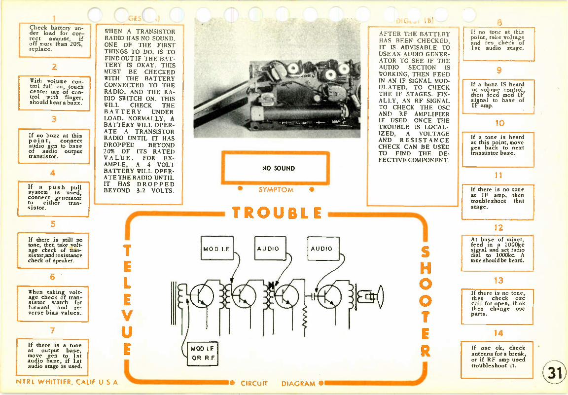
Check battery un-der load for cor-rect amount, if off more than 20%, replace.
2
With volume con-trol full on, touch center tap of con-trol with finger, should hear a buzz.
3
If no buzz at this point, connect audio gen to base of audio output transistor.
4
If a push pull system is used, connect generator to either tran-sistor.
5
If there is still no tone, then take volt-age check of tran-sistor,and resistance check of speaker.
6
When taking volt-age check of tran-sistor watch for forward and re-verse bias values.
7
If there is a tone at output base, move gen to 1st audio base, if 1st audio stage is used.
r' GES C,)
WHEN A TRANSISTOR RADIO HAS NO SOUND. ONE OF THE FIRST THINGS TO DO, IS TO FINDOUTIF THE BAT-TERY IS OKAY. THIS MUST BE CHECKED WITH THE BATTERY CONNECTED TO THE RADIO, AND THE RA-DIO SWITCH ON. THIS WILL CHECK THE BATTERY UNDER LOAD. NORMALLY, A BATTERY WILL OPER-ATE A TRANSISTOR RADIO UNTIL IT HAS DROPPED BEYOND 20% OF ITS RATED VALUE. FOR EX-AMPLE, A 4 VOLT BATTERY WILL OPER-ATE THE RADIO UNTIL IT HAS DROPPED BEYOND 3.2 VOLTS.
NTRL W HITTIER, CALIF U S
NO SOUND
MOD I F
OR R F
SYMPT OM •
TROUBLE
:E. CIRCUIT
Otut.,1 i13) 8
AFTER THE BATTERY If no tone at this point, take voltage
HAS BEEN CHECKED, and res check of IT IS ADVISABLE TO 1st audio stage. USE AN AUDIO GENER-ATOR TO SEE IF THE AUDIO SECTION IS WORKING, THEN FEED IN AN IF SIGNAL MOD-ULATED, TO CHECK THE IF STAGES. FIN-ALLY, AN RF SIGNAL TO CHECK THE ()SC AND RF AMPLIFIER IF USED. ONCE THE TROUBLE IS LOCAL-IZED, A VOLTAGE AND RESISTANCE CHECK CAN BE USED TO FIND THE DE-FECTIVE COMPONENT.
0
DIAGRAM • =11 11 MINI MMIN E J
9
If a buzz IS heard at volume control, then feed mod IF signal to base of IF amp.
10
If a tone is heard at this point, move gen back to next transistor base.
11
If there is no tone at IF amp, then troubleshoot that stage.
12 At base of mixer, feed in a 1000kc signal and set radio dial to 1000kc. A tone should be heard.
13
If there is no tone, then check osc coil for open, if ok then change osc parts.
14
If osc ok, check antenna for a break, or if RF amp used troubleshoot it.

1 Check battery voltage by leaving connected to set with set on.
2
If battery voltage is below 20% of rated value, re-place.
3
Locate all elec-trolytic capacitors and bridge them with another capacitor.
4
Leave set on while bridging. If sound increases as one is bridged, replace that capacitor.
5
If all capacitors have been checked, connect audio gen to base of output transistor.
6
If push pull cir-cuit, go to base of either transistor. Tone should be the same at each base.
7
It is normal for a weak tone to be present at this point. If very weak take voltage check.
DIGEST (A)
THE CAUSE OF WEAK SOUND COULD BE A BATTERY THAT IS LOW IN VALUE, OR A CIRCUIT THAT IS NOT AMPLIFYING AS MUCH AS IT SHOULD. MOST TRANSISTORS ARE NOT OF THE PLUG IN TYPE, AND THIS MEANS THAT WE CANNOT REPLACE THE TRAN-SISTORS FIRST, AS WE MAY TEND TO RE-LACE THE TUBES FIRST IN A RADIO USING VACUUM TUBES. UNDER THESE CIR-CUMSTANCES, IT IS ADVISABLE TO LO-CATE THE TROUBLE TO A DEFECTIVE CIR-CUIT BY MEANS OF A SIGNAL GENERATOR.
NTRI W HITTIER, CA.1: U S A
V
WEAK SOUND
• SYMPT O M •
TROUBLE
DIGEST (B)
THERE IS A VERY COMMON CAUSE OF WEAK SOUND IN A TRANSISTOR SET, AND THAT IS AN OPEN CAPACITOR. IN MOST CASES THIS WAS FOUND TO BE AN ELECTROLYTIC, AND UNDER THESE CON-DITIONS IT WILL BE SUGGESTED THAT ALL ELECTROLYTIC CA-PACITORS BE BRIDGED ONE AT A TIME AFTER THE BATTERY HAS BEEN CHECKED. IF THIS DOES NOT HELP, THEN THE GENERA-TOR CAN BE USED TO LOCALIZE TO ONE STAGE.
0
EN I MNI M M •11111111 11 ) • CIRCUIT DIAGRAM •
8 Measure resistance values carefully. Substitute speaker. If still weak, re-place transistor.
9
If tone ok at output base, move gen to center tap of vol-ume control, with control full on.
10
If a 1st audio transistor is used in set, then a loud tone should be heard at this point.
11
If volume control goes directly to output transistor, then tone will be weak.
12
If normal at volume control, feed in Mod IF at IF amp base. If weak check voltage
13
Continue moving gen back one stage at a time listening for a decrease in amplification.
14
If all stages ap-pear fairly normal, check chart on alignment.

1 Replace all bat-teries.
2
Check for a poor battery contact due to corrosion.
3
Make sure that batteries have cor-rect polarity.
4
Locate electrolytic capacitor on bat-tery line to ground.
5
This capacitor is the most likely cause of feedback.
6
Bridge this ca-pacitor with good one, replace if it cures trouble.
7
Bridge all capaci-tors on battery line to ground.
ST
A VERY COMMON1 TROUBLE THAT OC-CURS IN A TRANSISTOR RADIO IS THIS HOWL, SQUEAL, AND MOTOR-BOATING. IT IS CAUSED BY SIGNAL FEEDBACK, WHERE AT SOME POINT IN THE RADIO THE SIGNAL IS GOING FROM TRANSISTOR TO TRAN-SISTOR. ONE OF THE CAUSES OF THIS FEED-BACK IS A BAD BAT-TERY. THEREFORE, IT IS DESIRABLE TO CHANGE THE BAT-ERY FIRST. THIS IS MUCH BETTER THAN CHECKING ITS OPER-ATING VOLTAGE, BE-CAUSE IT WAS FOUND THAT THIS CONDITION OF FEEDBACK WOULD OCCUR EVEN WHEN THE BATTERY AP-
I PEARED NORMAL.
NTRI. W HITTIER, CALI'
I HOWLS, SQUEALS, MOTOR BOATING
I
r illi Milli. 11111111 I. F. Amp. Def.
• SYMPT O M •
V
TROUBLE
—r Filter
—47 Capec dor
U S A • CIRCUIT DIAGRAM •
.8) 8
MANY OF THE TRAN-SISTOR RADIOS USE. A SERIES OF BATTERIES THAT MAKE UP THE TOTAL VOLTAGE. IF ONE OF THESE IS DEFECTIVE, OR IS MAKING A POOR CON-TACT DUE TO COR-ROSION, THEN IT CAN BE THE CAUSE OF FEEDBACK. AFTER THE BATTERIES HAVE BEEN CAREFULLY CHECKED, AN OPEN CAPACITOR MAY BE SUSPECTED OR PER-HAPS POOR ALIGN-MENT.
0
Bridge capacitor connected from avc line to ground.
9
AVC line is tied to top of volume control through a resistor.
10
Some transistor radios use a spe-cial network in the IFs to prevent feedback.
1 1
This network may be defective.Check for resistor ca-pacitor circuit in IFs.
12
This circuit will go from base to base of the two IF stages.
13
If all appear normal , realign radio.
14

Check the battery voltage with bat-tery connected and set on.
2
If more than 20% below rated value replace.
3
Some transistor radios require al-most full rated volt-age to operate correctly.
4
If in doubt, replace battery anyway.
5
Substitute speaker, be sure to discon-nect speaker in set first.
6
If speaker is ok, connect audio sig-nal to base of out-put transistor.
7
If distortion pres-ent, two tones in-stead of one, take forward bias check. Check resistors.
DIGEST (A)
WHEN A TRANSISTOR RADIO HAS DISTOR-TION, IT CAN MEAN THAT THE BATTERY IS LOW ON OUTPUT, OR THAT ONE OF THE TRANSISTOR CIRCUITS HAS INCORRECT FOR-WARD BIAS. OF COURSE ONE OF THE FIRST THINGS TO DO, IS TO CHECK THE BATTERY. IF THIS APPEARS NORMAL, THEN THE TROUBLE SHOULD BE LOCAL-IZED TO ONE OF THE TRANSISTOR CIRCUITS BY MEANS OF A SIG-NAL GENERATOR IF POSSIBLE. IF A GEN-ERATOR IS NOT USED, THEN A CLOSE VOLT-AGE CHECK MUST BE MADE FOR CORRECT FORWARD BIASING.
NTRL W HITTIER, CALIF U S A
V
DISTORTION
ON ALL STATIONS
• SYMPT O M •
TROUBL
DI GEST (B)
THE AMOUNT OF FOR-WARD BIAS THAT A TRANSISTOR CIRCUIT USES, DEPENDS UPON THE AMOUNT OF SIG-NAL THAT IT MUST HANDLE. FOR EX-AMPLE, THE MIXER STAGE WILL BE HAND-LING A VERY SMALL AMOUNT OF SIGNAL, PERHAPS DIRECT FROM THE ANTENNA STAGE, WHEREAS THE AUDIO OUTPUT TRAN-SISTOR WOULD HAVE A FAIRLY LARGE IN-PUT SIGNAL SINCE IT HAS BEEN AMPLIFIED ALL OF THE WAY THROUGH THE RADIO. HOWEVER, THE AMOUNT OF FORWARD BIAS ON ANY TRAN-SISTOR WILL SELDOM BE LARGER THAN .3 VOLTS.
0
UNI NI MI•1.1•1 = .1110) • _CIRCUIT DIAGRAM •
8 In push pull out-put, tone should sound same at base of both tran-sistors.
9
If one is different, run a voltage and resistance check on both transis-tors.
10
In push pull, all components in each stage should be the same.
11
If output stage appears normal, move gen back to I st audio base.
12
If sound is dis-torted here, take voltage and resist-ance check of circuit.
13
If distortion is on all stations it is likely to be in the audio circuits.
14
Check the coupling capacitors for a short or leakage. Replace transis-tors.

1
IReplace batteries.
2
Connect meter across volume control with a distorted station tuned in.
3
Should have a small negative voltage present.
4
Now switch to a good station, amount of negative voltage should have decreased.
5
Move meter to avc line going to the base oi one of the transistors.
6
Vary station se-lector, amount of base voltage should change as stations change.
7
With this trouble, base voltage will probably remain constant as dial is varied.
-. GEST ,A)
WHEN A RADIO, ANY RADIO, DISTORTS ON SOME STATIONS, BUT APPEARS NORMAL ON OTHER STATIONS, IT IS A GOOD INDICATION THAT THERE IS SOME TROUBLE IN THE AVC LINE. THE REASON FOR THIS, IS THAT IF THERE IS NOT ENOUGH BIAS ON THE IFS, THEN A WEAK STATION MAY PASS WITHOUT BEING TOO LARGE TO OVER-DRIVE THE TRANSIS-TOR, BUT IF A STRONG STATION COMES A-LONG IT WILL OVER-DRIVE THE TRANSIS-TOR, CLIPPING THE SIGNAL, WITH ITS RESULTANT DISTOR-TION.
V
1
DISTORTION
ON SOME STATIONS
TROUBLE
DIGEST (B)
SINCE IT IS THE PUR-POSE OF THE AVC LINE, TO CONTROL THE STRENGTH OF THE SIGNAL, THE FACT THAT SOME STATIONS ARE OPER-ATING NORMALLY, WOULD INDICATE THAT THE AUDIO STAGES ARE OKAY, AND THAT THE TROU-BLE MUST BE BACK OF THE DETECTOR. ONCE AGAIN, SINCE THE STATIONS ARE PASSING THROUGH THE MIXER, OSC, AND IFS, WE MUST CON-CLUDE THAT THE TROUBLE IS DUE TO INCORRECT BIAS, AND THE BIAS IS CONTROL-LED BY THE AVC. SOME TRANSISTOR RA-DIOS USE GERMANIUM CRYSTALS FOR THE AVC.
A.V CL.. A.VC
T Capaclithr
0 0
If base voltage does vary as dial is moved, then suspect bad transistor.
9
If base remains constant, check for shorted avc capacitor.
10
A VC capacitor will be connected from the avc line to ground.
11
This capacitor is usually an electrolytic type.
12
If avc capacitor is good, check for an open resistor on avc line.
13
If set uses crystal diode in the avc line, then try re-placing crystal.
14
When soldering crystal, be sure not to apply too much heat, as it will damage it.
NTRI. W HITTIER, CALI; U S A • CIRCUIT DIAGRAM •

1 Check battery for good connections to leads or metal contact.
2
U s e fine sand-paper to clean off any corrosion of battery contacts.
3
Take visual check of radio, apply slight pressure to parts mounted on chassis.
4
If set goes off and on as pres-sure to a part is applied, resolder part in circuit.
5
If set uses printed circuit board, ap-ply pressure to board at various points.
6
If a particular area appears to make set go off and on, resolder around that area.
7
If pressure at many points ap-pear to affect set, resolder entire board.
DIGEST (A)
ONE OF THE MOST DIFFICULT TROUBLES WITH TRANSISTOR RA-DIOS IS THEIR INTER-MITTENT OPERATION. MOST COMMON CAUSE OF THIS IS A POOR CONTACT WITH THE PRINTED CIRCUIT BOARD. VISUAL IN-SPECTION IS NOT TOO REWARDING, BECAUSE MOST OF THESE TROU-BLES ARE UNDER. NEATH THE SOLDER WHERE THEY CANNOT BE SEEN EVEN WITH A MAGNIFYING GLASS. BEST THING TO DO, ONCE A FEW QUICK CHECKS HAVE BEEN MADE, IS TO RESOLDER ALL TERMINALS ON THE PRINTED BOARD.
NTRL W HITTIER, CALIF U S A
INTERMITTENT OPERATION
• SYMPT OM •
TROUBLE Bad connection /./1
iransforrnar, oltee Ca use of 'neer-mi./lent operation
LE Amp
DIGEST (B)
INTERMITTENT OPER-ATION CAN BE THE RESULT OF POOR BATTERY CONTACTS, A BROKEN WIRE MAK-ING AND BREAKING CONTACT, OR A COM-PONENT PART BREAK-ING DOWN FOR A PERIOD OF TIME. ONCE THE NORMAL CHECKS HAVE BEEN MADE, IT MAY BE NECESSARY TO USE A SIGNAL GENERATOR SO THAT THE DEFECTIVE STAGE CAN BE ISO LA TED. APPLYING SLIGHT PRESSURE TO THE PRINTED BOARD SOMETIMES HELPS, ALTHOUGH IT MAY ALSO TEND TO BE CONFUSING BECAUSE PRESSURE AT ONE POINTON THE BOARD, MAY AFFECT A SEC-TION FAR AWAY.
0
9 CIRCUIT DIAGRAM •IM MMIN II MINE M J
8
Use small wattage iron to avoid damage to printed board.
9
If trouble persists use gen and fed in audio signal at top of volume control.
10
If intermittent at this point, con-centrate on audio circuit for poor contact.
11
If sound remains constant at volume control, feed in signal at IF, mod, to mixer base.
12
If intermittent here, then con-centrate trouble shooting to mixer, IF, and det.
13
If constant tone at mixer base, feed in 1000kc mod and set dial at 1000kc.
14
If intermittent, then trouble in osc. If constant, check antenna or RF.

Replace battery.
2
If battery not avail-able, check volt-age output under load. 1
3
Connect meter across battery then switch set on. If voltage drops slowly to low value, bat-tery is bad.
4
If battery appears normal, then trou-ble is in receiver.
5
Connect gen to audio output base after set has stopped operating.
6
If a tone is heard, audio output is okay.
7
If there is no tone, then check speaker, and oper-ating. svtoorlt. ages of transt
A DEFECTIVE BAT-TERY CAN BE THE CAUSE OF THIS CON-DITION. WHAT TAKES PLACE IS THAT WHEN THE SET IS SWITCHED OFF, BATTERY HAS MAXIMUM OUTPUT, AS RADIO IS SWITCHED ON, CURRENT STARTS TO FLOW, AND A DRAIN IS PLACED ON THE BATTERY, IF BATTERY IS OLD IT WILL SUPPLY THE AMOUNT OF CURRENT FOR A FEW MINUTES ONLY, THEN ITS OUT-PUT DROPS TO A VALUE TOO LOW TO OPERATE RECEIVER.
V
SET PLAYS THEN STOPS
Moil FT and R. f:
• SYMPT O M •
TROUBLE
Check for Ione de these /ooines
Antenna
NTRL W HITTIER, CALIF U S A • CIRCUIT LIIIMIIIMIIIMIMMIIII
DIk;1.!):
THERE IS ALWAYS A POSSIBILITY THAT SOME COMPONENT PART IS BREAKING DOWN UNDER OPERA-TION, A RESISTOR MAY BE OPENING UP, OR A CAPACITOR SHORTS. IF THIS IS THE CASE, THEN THE BEST APPROACH IS TO LET THE SET STOP PLAYING, THEN USE A GENERATOR TO FEED IN A SIGNAL STARTING AT THE AUDIO OUTPUT STAGE AND WORK BACK TO-WARD THE ANTENNA. AT THE POINT WHERE THE SIGNAL WILL NOT PASS, YOU WILL FIND YOUR DEFECTIVE COMPONENT.
0
111.111•11 = =111•111 111111 •111 ) DIAGRAM •
a If tone is at out-put transistor, move gen back to 1st audio tran-sistor base.
9
If tone at this point, then check operating voltages of 1st audio tran-sistor.
10
With tone at 1st audio, move gen back to base of IF transistor.
11
Feed in a mod IF signal and listen for tone.
12
If no tone, then check voltages of IF transistor and resistance check of det.
13
If tone passes IFs, use same procedure on mixer base.
14
Feed in 1000kc mod to mixer base, set dial to 1000kc. If no tone check osc circuit.

Disconnect bat-tery., and measure resistance across terminals with switch OFF.
2
Should have an infinite reading. If some reading present, trouble due to leakage.
3
Make sure that switch turns set off.
4
Check leads from battery to chassis for possible short to some part.
5
If switch reading infinite, then trouble is occuring when set is on.
6
Leave battery off, and unsolder any capacitor con-nected from bat-tery line to ground.
7
Check each one of these capacitors for leakage.
DIGEST (A)
ONE OF THE BIG ADVANTAGES OF A TRANSISTOR RADIO IS THAT THE CURRENT DRAIN ON THE BAT-TERY IS SO LITTLE. MAIN REASON FOR THIS IS THE FACT THAT THE TRANSIS-TOR HAS NO HEATER, AND THEREFORE THE ONLY CURRENT DRAIN ON THE BATTERY IS THE TRANSISTOR CUR-RENT THAT IS VERY SMALL. UNDER NOR-MAL OPERATION, THE BATTERY OF A TRAN-SISTOR RADIO SHOULD LAST AT LEAST 3 MONTHS.
V
BATTERIES ARE USED
UP TOO FAST
SYMPT OM •
TROUBLE
May have LeaIrape
Resi.stanee
E I
-I- May be
Leaky
Leeke9e ,17d y he ,,, one of fhese ,oatiAs
A
DIGEST (B)
IF A TRANSISTOR RADIO BATTERY RE-QUIRES CHANGING EVERY MONTH, OR PERHAPS SOONER, THEN SOME SHORT SHOULD BE SUSPECT-ED IN THE BATTERY LINE. BEST METHOD TO USE WITH THIS KIND OF A TROUBLE IS TO TAKE RESIST-ANCE CHECKS ALONG THE BATTERY CIR-CUIT. WHEN DOING THIS, IT WILL BE FOUND NECESSARY TO DISCONNECT CER— TAIN SECTIONS OF THE RECEIVER IN ORDER TO DETERMINE IF THE SHORT EXISTS IN THAT PATH.
0
CIRCUIT DIAGRAM •• 1 =.11 =111 = J
8
, Bear in mind that ' electrolytics will have a high leak-
. age resistance.
9
If all of these ca-pacitors are okay, take resistance checks of each transist r c
10
Look for a de-crease in the nor-mal resistance to common negative.
11
Keep in mind that transistors have a low resistance between base and emitter.
12
It may be neces-sary to unsolder each transistor in order to eliminate a parallel path.
13
In some cases, the speaker will cause a partial short due to its metal frame.
14
NITR L W HITTIER, CALIF U S A

Check for a poor battery contact. If necessary bend metal clips.
2
Apply slight pres-sure to parts mounted on chas-sis.
3
If noise varies as pressure is ap-plied, check con-nections at that int.
4
May have to re-solder circuit if a printed board is used.
5
If trouble persists, try to isolate to one stage by using signal generator.
6
Connect audio gen to base of output transistor,unsolder coupling capacitor to base.
7
..AGEST ,A)
NOISY OPERATION CAN OCCUR IN A TRAN-SISTOR RECEIVER FOR THE SAME REASONS AS IN A VACUUM TUBE TYPE OF RECEIVER. POOR CONTACTS, CA-PACITOR BREAKING DOWN, IF TRANSFORM-ER SHORTING FROM PRIMARY TO SECOND-ARY, ETC. THE SAME TYPE OF TROUBLE-SHOOTING PROCE-DURE CAN BE APPLIED IN THE TRANSISTOR RECEIVER, AS IN ANY OTHER TYPE. OF COURSE, THE TROU-BLE COULD BE CAUSED BY A DEFEC-TIVE, TRANSISTOR, BUT SINCE THEY ARE US-ALLY OF THE TYPE THAT IS SOLDERED IN POSITION, THEY ARE NOT RFPI AC M) FIRST
V
NOISY OPERATION
A 'Ile nna May be 1003.0
• SYMPT OM •
TROUBLE
NTRL W HITTIER, CALIF U S A L NIIIMIIIIIII• CIRCUIT
If tone is noisy, then trouble is in output transistor stage.
Th•ans fo rme may be defective
r Trans fomer
A.V.C.
D (B)
ONE THING TO CHECK, IS FOR LOOSE CON-NECTIONS. COMMON AMONGST THESE ARE THE ANTENNA AND BATTERY LEADS. IN MANY CASES THE METAL CLIPS, CON-NECTING THE BAT-TERY TO THE RADIO, WERE LOOSE OR COR-RODED. IF SOME COM-PONENT IS AT FAULT, THEN THE TROUBLE MUST BE LOCALIZED TO THE DEFECTIVE CIRCUIT BY MEANS OF THE SIGNAL GEN-ERATOR.
Contact or Lead I may be
DIAGRAM .
0
8
if tone is clear, then reconnect coupling capacitor and put gen at base of 1st audio.
9
Unsolder coupling capacitor to 1st audio. If tone is noisy, trouble is in 1st audio.
10
With clear tone at 1st audio, recon-nect capacitor and connect gen to IF base.
11
Feed in a mod IF, if a noisy tone present move gen to collector.
12
If noisy at col-lector suspect a defective IF trans-former. Replace.
13
Continue this method of injecting a signal until noisy stage isolated.
14

Wrap two turns of wire around loop antenna and con-nect to signal gen.
2
Place meter across volume control, dc volts range 3v.
3
Output may be negative or positive, be sure meter has correct polarity.
4
Feed in a mod IF signal. Meter should indicate, and a tone should be heard.
5
Adjust all IF trans-formers while ob-serving meter. Ob-tain maximum read-ing.
6
Tone will also increase or de-crease with ad-justments.
7
DI GEST (A)
ALIGNMENT OF A TRANSISTOR RECEIV-ER CAN IMPROVE THE AMOUNT OF VOLUME, DECREASE THE NOISE IN THE BACKGROUND, AND IN GENERAL IM-PROVE THE OVERALL RECEPTION OF THE RECEIVER. TECHNI-CALLY THIS IS REFER-RED TO AS INCREAS-ING THE SENSITIVITY AND SELECTIVITY, AND REDUCING THE NOISE LEVEL. MOST TRANSISTOR RECEIV-ERS ARE EASY TO ALIGN, AND SIMPLY REQUIRE A MEANS OF COUPLING THE SIGNAL TO THE ANTENNA OF THE RECEIVER FROM A FEW TURNS OF WIRE CONNECTED TO THE SIGNAL GENERATOR.
V
ALIGNING TRANSISTOR
RADIOS
Gcnervito, Feed/ne rn /41,o' I. F. then Med fr?Fi
• SYMPT O M •
TROUBLE
NTRL W HITTIER, CALIF p S_A L .. IIIIIII IIIMINIIIINII MII CIRCUIT
Most transistor IFs have only one adjustment screw.
DI GEST (B)
ONCE THE SIGNAL FROM GENERATOR IS COUPLED TO THE RE-CEIVER, THE IF SIG-NAL IS FED IN, AND THE IF TRANSFORM-ERS ARE ADJUSTED TO GIVE A MAXIMUM READING ON THE METER SCALE. MANY TIMES IT IS NOT NE-CESSARY TO USE A METER, FOR THE IFS AND RF CIRCUITS CAN BE ADJUSTED BY SIMPLY LISTENING FOR THE LOUDEST TONE. USING THE METER IS A MORE ACCURATE METHOD OF ALIGNMENT.
0
Volume Cont.-o/
111 1111 •111111111011111 ) DIAGRA M •
8
Now feed in a 1400kc signal and set radio dial to the 1400kc point.
9
Locate osc trim-mer screw mounted on side of tuning cap.
10
Osc section of tuning cap has the small plates.
11
Adjust osc trimmer until maximum reading, or tone, is present.
12
Now feed in 1500kc signal, and set radio dial to 1500kc point.
13
Adjust mixer trim-mer on tuning cap for max. reading, or tone.
14
Alignment is now complete.

Replace Oscillator,
R.F. amplifier, and
Mixer tubes.
2
If set still drifts,
check to see if
AFC is used.
3
If set uses AFC, a line from detector to oscillator will be present.
4
In schematic this line comes from det., through C26, R27, to X3 afc diode
5
If there is no AFC used, trouble must be in Oscillator circuit.
6
Replace all ca-pacitors associated with oscillator.
7
In most cases these will be spec-ial temperature compensated types.
-AGES I kA)
WHEN A RECEIVER DRIFTS ON FM OPER-ATION, IT INDICATES THAT THE LOCAL OS-CILLATOR IS CHANG-ING FREQUENCY SLIGHTLY CAUSING THE STATION TO FADE OUT. MANY OF THE FM SETS INCOR-PORATE AN AUTO-MATIC FREQUENCY CONTROL SYSTEM (AFC) TO PREVENT SUCH A DRIFT FROM OCCURING. HOWEVER, IF THE SYSTEM IS DE-FECTIVE, THEN THE DRIFTING SYMPTOM WILL BE NOTICED.
V
T 3
I r- flI PIC 1
11 .4 I 1 C' TC14
Mt
TROUBL
C15 - 001
Westinghouse
DRIFTS OFF STATION
1 I •
C22 4111110
SYMPT OM
V919 loov,
1/2 12 AT 7
FM OSC
1 CII
17 101 R
T 4 7 110 1,470
C20 t774.1011 1
NTRL W HITTIER, CALIF U S A • CIRCUIT LIMMIIIMMIIIMINIIIIM=I
•
C 26 isoo I NNF
Dli;ES1 (B) • - •
AFC SYSTEMS ARE SIMILAR TO AVC FOUND IN AM. ONE OF THE MAIN DIFFER-ENCES IS THAT THE CORRECTION VOLT-AGE IS FED TO THE OSCILLATOR CIRCUIT IN FM, WHEREAS IT IS FED TO THE IF AND RF CIRCUITS IN AM. IN THE AFC CIRCUIT, THE OSCILLATOR FREQUENCY IS MAIN-TAINED BY VARYING THE AMOUNT OF GRID VOLTAGE. IF THE OS-CILLATOR TENDS TO DRIFT, THEN A COR-RECTION VOLTAGE IS FED TO GRID BRING-ING OSCILLATOR BACK ON FREQUENCY.
134 217
VP
0
1=1 =1 =11 1 MINNIM MI )IllA r,PAAA •
8
1Be sure to replace with exact same type.
9
If set uses AFC circuit, check or replace all com-ponents in circuit.
10
In a weak signal area, AFC may not operate well.
11
Try an outside an-tenna, or check one that set is using.
12
If indoor type, may be broken or not connected.
13
If strong stations are normal, but weak ones drift, then signal is too weak.
14
(4-0

1 On AM/FM com-binations check operation of AM section.
2
If AM normal, trou-ble must be in FM det. circuit or IF RF stages.
3
If AM also inter-mittent, Trouble is in power supply or audio stages.
4
On FM receiver on-ly, check for audio operation by plac-ing finger at top of volume cont.
5
If buzz constant, then audio section okay. If buzz inter-mittent, then trou-ble in audio.
6
If trouble isolated to audio, use audio gen. at grids of tubes to find bad stage.
7
Be sure to replace tubes first with this condition.
1
DIGEST (A) WITH INTERMITTENT
OPERATION OF FM ON
AN AM/FM COMBINA-
TION RECEIVER,
CHECK TO SEE IF
THIS CONDITION EX-
ISTS ON THE AM SET-
TING. IF IT DOES,
THEN THE TROUBLE
IS EITHER IN THE
POWER SUPPLY, OR
THE AUDIO SECTION
OF THE RECEIVER.
ON AM FM SET ONLY,
THEN THE TROUBLE
CAN BE ATANY POINT
IN THE RECEIVER. USE OF A GENERATOR
WILL HELP IN DETER-MINING THE SECTION
AT FAULT.
Motorola
V3 I 2BA6
AM & 2ND FM IF AMP
iINTERMITTENT OPERATION • SYMPT O M •
TROUBLE
VA 11AU6
FM LIMITER A AM DO
05 IZAL5
FM RATIO DE7 12
DIGEST (B) IF THE AM SECTION OPERATES NORMAL-
LY, BUT THE FM IS IN-
TERMITTENT, THEN
THE TROUBLE IS ISO-
LATED TO THE FM
DETECTOR, FM I.FS,
OR THE FM R.FS.
SINCE ANY SECTION
OF THE RECEIVER
CAN CAUSE THIS CON-
DITION, IT IS ADVISA-
BLE TO ISOLATE IT
TO THE DEFECTIVE
STAGE AS QUICKLY
AS POSSIBLE. THE
PURPOSE OF THIS
CHART IS TO PROVIDE
A PROCEDURE TO
ISOLATE THE TROU-
BLE TO A DEFECTIVE
STAGE.
0 0
LIIIIIIIIIM=M1 IIINIMINIIIIM=M11111•1111111) NTRL WHITTIER, CALIF U S A • CIRCUIT DIAGRAM •
8 If trouble is in FM detector or IF, RF stages, follow pro-cedure indicated below.
9
Connect sig. gen. to grid of last I.F. Feed in 10.7 mc unmodulated.
10
Connect meter as indicated in steps 3and 4 of FM R.F. alignment chart.
11
low volts DC range and note if reading is constant, if not, trouble in last I.F. or det.
12
If meter shows con-stant reading move gen. back to each I.F. grid until mix-er.
13
Look for fluctuating reading. If all nor-mal, set radio dial and gen. to 98mc.
14
If meter varies now, osc. circuit de-fective. If normal then trouble in R.F. stage.

Replace all tubes.
2
If a combination
AM/FM set, check
operation on AM.
3
If normal on AM, then trouble is in FM detector or FM circuit before de-rector-
4
If noisy on AM, trouble in audio circuit or common IFs.
5
Troubleshoot for noisy AM operation, use chart #17 of radio Tele-Vue.
6
If FM only is noisy,
check detector cir-
cuit.
7
If a ratio detector
is used, change
stabilizing capa-
,A)
NOISY OPERATION ON AN FM RECEIVER, MAY BE DUE TO DE-FECTIVE COMPO-NENTS IN THE SET, POOR ALIGNMENT OF THE DETECTOR, OR TOO WEAK A SIGNAL
INPUT. THE LIMITING ACTION OF THE DE-
TECTOR CIRCUIT IS ONE OF THE MAIN
REASONS THAT FM IS SO NOISE FREE. IN
THE DISCRIMINATOR, LIMITING IS DONE BY A SPECIAL CIRCUIT CALLED THE LIMITER. WHEREAS, IN THE RA-TIO DETECTOR, THE LIMITING IS DONE BY THE ELECTROLYTIC STABILIZING CAPACI-TOR ACROSS DETEC-TOR TUBE.
V
rNOISY OPERATION
LIMITrR 6AU6
• SYMPT O M •
TROUBLE
citor.
NTRL WHITTIER, CALIF U S A • CIRCUIT L 11111 =111 1111 . DIAGRAM Westinghouse •
(B)
IF A RECEIVER USES A DISCRIMINATOR,
THE STRENGTH OF THE INPUT SIGNAL IS
VERY IMPORTANT BE-CAUSE TOO WEAK AN
INPUT WILL PREVENT THE LIMITER FROM OPERATING COR-RECTLY, AND AS A
RESULT SOME OF THE AMPLITUDE VARIA-TIONS WILL PASS TO
THE DETECTOR STAGE AND CAUSE NOISY OPERATION.
INCORRECT ALIGN-MENT WILL ALSO RE-DUCE THE SIGNAL TO THE LIMITER, WITH THE SAME RESULTS.
0
8
If a Discriminator
is used, check limiter components.
9
Connect generator to last IF grid, feed in a 10.7 mc modulated signal.
10
Move off station and rock gen dial around IF. Listen for tone.
11
If tonenoisy, check IF components and detector parts.
12
If parts appear okay, try aligning detector. If still noisy, replace de-tector transformer.
13
If tone at last IF is normal, move gen back to 1st IF. If noisy, check parts.
14
Continue checking Mixer and RF as above. If normal, try aligning IF & RF

1 If set is a combina-tion AM/FM, check operation on AM.
2
With distortion on AM and FM, trouble is in audio stages. Check tubes.
3
If distorted on FM only, change de-tector, IF, and RF tubes.
4
If set is FM only, change all tubes and troubleshoot audio stages.
1 5
Use sameprocedure as for distortion on an AM set.
6
If trouble appears to be other than in audio, check de-tector first.
7
Take resistance checks of all re-sistors around de-
•
DIGEST (A) DISTORTION CAN OC-CUR IN AN FM RE-CEIVER DUE TO TROU-BLE IN THE AUDIO
SECTION AS WELL AS TROUBLE IN THE DE-TECTOR AND POOR
ALIGNMENT OF THE IFS. TROUBLESHOOT-ING THE AUDIO
STAGES OF AN FM SET
SHOULD HOLD NO
PARTICULAR TROU-BLES SINCE THEY ARE THE SAME AS FOUND IN AM. THE DETECTOR CAN
CAUSE DISTORTION BECAUSE ITS OUTPUT DEPENDS ON THE CORRECT OPERATION OF ITS TWO SECTIONS.
V
0 0 73
013 1000
1 4
DIGEST (B)
19.1 1111111111111111 11 111 1 111 1 6 -•
'1111/
1
DISTORTION F I • SYMPTOM •
uZROUBL E9 2ND IF v3 DETECTOR-AF AMP
V4
T4
IC31 1-4111110
Admiral
032 .005
014 2.1k
C 33 2204110 I 10% tector.
NTRL WHITTIER, CALIF U S A • CIRCUIT LI111111111111
Nii 1120 - NI -C41 1311 0.-, 4 T.001 f I 50V
- C30 r -
022 I 021 MEC 1 1 1I1 VOLUME
FM DETECTORS OPERATE ON A CHANGE IN FREQUEN-CY RATHER THAN A CHANGE IN AMPLI-TUDE AS FOUND IN AM RECEIVERS. IF THE DETECTOR IS NOT ALIGNED OR BAL-ANCED CORRECTLY, THEN IT WILL NOT PRODUCE THE SINE WAVE OUTPUT THAT IT SHOULD. THE RE-SULT OF THIS WILL BE DISTORTION. SEPA-RATE CHARTS ON THE ALIGNMENT OF THE DISCRIMINATOR AND RATIO DETECTOR ARE INCLUDED IN THIS PACKAGE. RATIO DE-TECTOR HAS A PLATE AND A CATHODE OF TUBE TIED TO DE-TECTOR TRANSFOR-MER.
023 101111
C43 .01 0 If -
C3/ LC42 .022 .005
0 0
8 Look for leaky or shorted capacitors around detector.
9
In ratio detector, replace electrolytic across output of circuit. (Usually 4 - 8 MED.)
10
In discriminator, check stage before detector. This is called the limiter.
11 Limiter load res-may have changed value, or open plate decoupling capacitor.
12
If all of the above appears to be nor-mal, check align-ment of detector & IFs.
13
14

If receiver is AM/ FM comb, check operation of AM.
2
If AM weak, then trouble is in power supply or audio.
3
If AM normal, trou-ble in FM IF or RE stages.
4
If receiver is FM only, check opera-tion of audio sec-tion.
5
In any case, re-
place tubes first.
6
If audio weak, con-centrate on power supply and audio stages.
7
VIA 1/2 HCCIIS FM If NAP
If audio normal, connect gen to grid of last IF. Feed in 10.7 mc modulated.
WEAK SOUND IN AN F.M. RECEIVER MAY BE DUE TO A DEFEC-TIVE AMPLIFIER IN THE AUDIO, IF, OR RF STAGES, OR POS-SII3LY POOR ALIGN-MENT. HOWEVER, TUBES SHOULD BE CHECKED FIRST, THEN A GENERATOR CAN BE USED TO CHECK EACH OF THE STAGES. ALIGNMENT SHOULD BE THE LAST THING TO THINK OF AS THE CAUSE. UN-DER NO CIRCUM-STANCES SHOULD YOU ATTEMPT AN ALIGN-MENT BY EAR.
V
WEAK SOUND
• SYMPT OM •
TROUBLE FM TUNER UNIT
— C1 =1—
El DETAIL
d( ait • a rt,*
iz r
ad _ 6 220
TAIT AC cc
5 6 3 LINE CORD
— ANTENNA „ 100T
Z2K
ANT TERM —;20 (CIP CA M PIT
M CI)
00•lIl ACT PO2 1ST AN? con
CT AIR IS M = 2 • C TO ••
2112C1 MACS M I MI
NTRL W HITTIER, CALIF U SA • CIRCUIT
a
Motorola
V111 112HCC85 CONV
SIMILAR METHODS OF TROUBLESHOOTING CAN BE APPLIED TO AN F.M. SET WITH WEAK SOUND, AS ONE WOULD USE ON AN A.M. SET WITH WEAK SOUND. HOWEVER, BF.-CAUSE OF THE TYPE OF DETECTOR AND FREQUENCIES USED, THE IF AND RF STAGES REQUIRE SPECIAL ATTENTION. THE AUDIO CIRCUITS CAN BE CHECKED IN THE SAME MANNER. IF THE RECEIVER IS OF THE A.M./E.M. TYPE, THEN THE TROUBLE CAN BE LOCALIZED I3Y CHECKING OPERA-TION OF THE A.M. SECTION.
1/7 12806
I ST FM F MAP
so,
SI SHOWN IN AFC-IN POSITION (SACS OP Inns
AS VI OLA MOO TOO)
to minin
DIAGRAM •
VS1
0
Rock gen. dial back and forth around 10.7 mc. Should hear clear tone.
9
If tone weak at last IF, take Volt-
, age and resistance checks.
10
With normal tone at last IF, move gen to next IF and repeat steps.
11
Repeat above steps at mixer grid. If tone normal here, move to RF grid.
12
Feed in 100 mc at RF grid, and set radio dial to 100mc
13
If tone weak at this point, then troubleshoot RF stage.
14
If all appear nor-mal, check align-ment charts De-tector first, then

1 I If an AM/FM com-bination, check to e if the AM is
L seorking.
2
If set is completely dead, check all tubes, power sup-ply, and audio stages.
3
If AM still working, trouble is either in FM detector or IF, RF stages.
4 fr set Is 1•111ronIy, check all tubes, power supply, and audio stages for operation.
5
To check operation of detector connect generator to grid of last IF at 10.7 mc.
6
Modulate signal and move generator dial back and forth around 10.7 mc.
7
If a tone is heard, then detector is okay. Be sure audio stages are working when you do this.
DIGEST (A)
WHEN AN FM SET STOPS PLAYING, IT MAY BE DUE TO TROU-BLE IN ANY SECTION OF THE SET. IF IT IS AN A.M./F.M. COM-BINATION, FIRST DE-TERMINE IF THE A.M. IS STILL WORKING. IF SO, THEN THE POWER SUPPLY AND AUDIO SECTIONS ARE OKAY. IF THE SET IS OF THE F.M. TYPE ONLY, THEN IT BE-COMES A CASE OF ISOLATING THE TROU-BLE TO EITHER THE AUDIO OR IF RF CIR-CUITS.
NO SOUND
T E' 4' L
LIIIIMII MINII IIIIIMIIN NTRL WHITTIER, CALIF U S A • CIRCUIT
1/2 19EA8 1ST IF
V24
CIS Sotv
OF 0
_[44 'NEC
044
4.24E0
411
• SYMPTOM
TROUBLE
1/2 19EA8 211D If
V2I1
.011.' 1110 2
CC'
12BN6 DETECTOR
.1•11•1
IMPIM
COO .00 ,
COO
024 411141 10%
10%
14
01:1110
COO 005
V%
45,
DIGEST (B)
TROUBLESHOOTING THE AUDIO SECTION OF AN F.M. SET SHOULD HAVE NO PROBLEMS SINCE THE SAME PROCEDURES CAN BE APPLIED AS IN THE CASE OF NO SOUND FOR AN A.M. RADIO. HOWEVER, THE DIFFERENCES COME IN WHEN THE TROUBLE IS IN THE IF OR RF STAGES, AS HIGHER FREQUENCIES AND DIFFERENT DE-TECTORS ARE FOUND. GREAT CARE MUST BE TAKEN WHEN PROB-ING AROUND THE RF STAGES IN CASE THE ALIGNMENT IS DIS-TURBED.
COO 121104
/..f -1r
.0°209,
IIQ
0-400
Admiral
.00I
0
8
If there is no tone, move gen. to last IF plate and repeat step #6.
9
If still no tone, then detector is defective. Take resistance check of circuit.
10
If tone is heard at last IF plate, but not at grid, then IF is bad. Take E and R checks.
11
If signal passes at IF grid, move gen back to next IF and repeat steps.
12
Use same proce-dure at mixer grid, if tone heard feed in 100 mc and set _radio dial ar 1 (Maw
13
Rock dial of gen around 100 mc, if no tone, osc not working take E and R checks.
14
If Mixer and Osc appear okay, then trouble in RF amp. Take E and R checks of RF.
DIAGRAM •

1.
Move to an off station or disable Local Osc to pre-vent interference.
2
Place VTVM a-cross electrolytic stabilizing capaci-tor on low DC volts. (Pni t C itt rivulet)
3
Conn ect signal generator to grid of last IF amp.
4
Feed in a 10.7 mc unmodulated sig-nal. Maximum out-
, put.
5
Adjust primary of detector transform-er while observing VTVM reading.
6
Adjust for a maxi-mum reading on meter.
7
Remove VTVM and set needle at zero center position
-IGES CA)
IN FM CIRCUITS, ALIGNMENT IS VERY IMPORTANT. GOOD ALIGNMENT INSURES NOISE FREE, UNDIS-TORTED OPERATION WITH HIGH FIDELITY. POOR ALIGNMENT CAN RESULT IN DIS-TORTION, NOISY RE-CEPTION, AND WEAK SOUND. HOWEVER, CERTAIN IMPORTANT STEPS MUST BE TAK-EN BEFORE ATTEMPT-ING ALIGNMENT. COR-RECT USE OF THE PROPER EQUIPMENT, AND THE KNOWLEDGE OF WHERE TO PLACE THE EQUIPMENT, ARE ALL PART OF THE PRELIMINARY WORK.
NTR1 WHII TIER, CALIF U S A L IIIIMIMIIIIIIIMIN• EIRCUIT
ALIGNING THE RATIO DETECTOR WITH VTVM • SYMPT OM •
TROUBLE
T44,
1c)
T4B
T c 8 0000
V 4B
22K
R17 100K
Westinghouse
DIAGRAM •
R18 100K
DiGE;,1 (B)
THERE ARE BASIC-ALLY TWO TYPES OF DETECTORS USED. ONE OF THESE IS THE RA TIO DETECTOR, AND THE OTHER IS THE DISCRIMINATOR. IN THIS CHART WE SHALL DISCUSS THE ALIGNMENT OF THE RATIO DETECTOR. THE ALIGNMENT CAN BE DONE WITH A GEN-ERATOR AND VTVM, THIS WILL USUALLY SUFFICE. FOR A MORE ACCURATE ALIGN-MENT, THE SCOPE CAN BE USED IN PLACE OF THE VTVM.
0
8 Connect VTVM be-tween junction of resistors and audio take off. (Points A
9
May be necessary to add two 100k resistors as shown in diagram.
10
Some receivers have resistors in circuit already.
11
Audio take off leads to deem-phasis network and volume control.
12
Use low DC volts scale. Adjust sec-ondary of det trans-former for zero re•nri.r re•ading
13
Be sure that needle rests on zero cent-er position, after aligning.
14
Slight movement of secondary adjust-ment screw should swing needle right o I

1 Disconnect the an-tenna and ground the grid pin of osc. if possible.
2
Connect gen. to grid of tube before detector. (this should be limiter stage.)
Connect meter at junction of cathode resistors of de-tector and ground. (Point A.)
4
Set gen at 10.7 mc unmodulated, with maximum output. Put meter on low D.C. volts.
5
Detune secondary of Det. transformer by turning adjust-ment screw several tu rns.
6
Adjust primary for a maximum reading on meter.
7
Remove meter and adjust needle for zero center setting.
DIGEST (A)
THE DISCRIMINATOR USED IN FM PROVIDES A GREATER OUTPUT THAN THE RATIO DE-TECTOR, BUT IT RE-QUIRES THE USE OF A LIMITER STAGE PRIOR TO THE DETECTOR. SINCE THIS MEANS AN ADDITIONAL CIR-CUIT, AND THERE-FORE A GREATER COST FOR THE RADIO, MOST RECEIVERS USE THE RATIO DETECT-OR. THE DISCRIMINA-TOR CIRCUIT CAN BE RECOGNIZED BY THE DETECTOR TRANS-FORMER SECONDARY THAT CONNECTS TO THE PLATES OF THE DETECTOR DIODE.
ALIGNING THE DISCRIMINATOR WITH
THE VTVM
LIMITER
V
• SYMPT OM •
TROUBL
DISC.
DIGEST (B)
THE ALIGNMENT PRO-CEDURES FOR THE DISCRIMINATOR ARE VERY SIMILAR TO THOSE USED FOR THE RATIO DETECTOR. THE POSITION OF THE METER DURING ALIGN-MENT IS PERHAPS THE GREATEST DIF-FERENCE BETWEEN THE PROCEDURES. IT IS VERY IMPORTANT THAT THE GENER-ATOR USED FOR THE ALIGNMENT BE AS AC-CURATE AS POSSIBLE, AND CHECKED FRE-QUENTLY FOR CALI-BRATION.
0
NTRl W HITTIER CALIF US A IL I MIII I MININ I MMEM MI111 111 •111 ) 9. CIRCUIT DIAGRAM •
8 Connect meter a-cross both cathode resistors of detect-or. (Points B & C)
9
With gen. still con-nected, meter will show reading above or below center
10
Adjust secondary of det. transformer for a zero center reading on meter.
11
With correct align-ment, needle will move above and below zero as screw is rocked.
12
Do not use a metal screwdriver for this alignment. It will cause detuning due to metal.
13
14

1 For Ratio detect-ors, connect meter across stabilizing capacitor at de-
2
For Discriminators, connect meter a-cross grid resistor of limiter tube.
3
Connect Signal gen-erator to grid of stage before last IF.
4
Feed in a 10.7 inc unmodulated signal. Set meter to low voltage setting.
5
Meter may have to be set on negative volts range.
6
Increase output of gen. to give notice-able reading on meter.
7
Adjust Transformer in plate circuit of stage gen. con-nected to, for max. reading on meter.
GUS. A)
ALIGNING THE I.F.S IN AN FM RECEIVER CANNOT BE DONE WITHOUT THE USE OF ALIGNMENT EQUIP-MENT IF THE RESULTS ARE TO BE CORRECT. THE GENERATOR USED SHOULD BE WELL CALIBRATED AND CHECKED A-GAINST A CRYSTAL FOR ACCURACY. IT IS POSSIBLE TO ALIGN WITH ANY TYPE OF SIGNAL GENERATOR, BUT THE MORE AC-CURATE THEY ARE, THE BETTER THE RE-SUL TS.
NTRL W HITTIER, CALIF U S A
V
F.M. I.F. ALIGNMENT
• SYMPT O M •
TROUBLE v,. VII [ST IF 2ND IF 6BA6 6BA6 LIMITER
6AU6
OS
sw2
75 IRO CALIF 407 ME
TI LIMITER
C 21 .0022
C 30 D047 -r
531 221
I IC3I4I:1 0I s
CVT 4-TO M *to mi°44° :!,. _
T 7 RATIO DET 107 MC
1
14 y 47011
ft 31 735
4.51
2▪ 20 It
VR I
CIRCUIT
Westinghouse
DIAGRAM •
C 32 047 I
of, t (Fs)
THE DIFFERENCE BE-TWEEN ALIGNING THE I.F.S OF A RECEIVER USING A RATIO DE-TECTOR, OR A DIS-CRIMINATOR, ARE ON-LY IN THE POINTS OF CONNECTION FOR THE METER. SINCE THE ALIGNMENT OF A RECEIVER SO GREATLY IMPROVES THE OPERATION AND QUALITY OF SOUND, IT IS RECOMMENDED THAT ALIGNMENT BE CHECKED ON ALL FM RECEIVERS BROUGHT IN FOR REPAIR.
VI3 FM GET
6AL5
IS
MM, MMT
0
8
Move generator back to next _pre-vious stage. This may be mixer grid.
9
Feed in same fre-quency of 10.7 mc and adjust plate transformer for maximum on meter.
10
Continue moving gen. back until Mixer plate trans. has been adjusted.
11
This should com-plete I.F. align-ment.
12
Do not attempt to readjust each IF transformer while gen. at mixer grid.
13
This may tend to peak the I.F., and narrow the band-width.
14

1
Disconnect antenna.
2 connect signal gen. to antenna termi-nals. Insert 270 ohm res. in series with hot lead.
3
' in Discriminator type det., place meter across grid res. of limiter.
4
In Ratio type det., place meter across electrolytic stabi-lizing cap.
5
Make sure that dial pointer sets at end of dial when tuned to end.
6
If it doesn't, ad-just it to correct position manually.
7
Now set dial to 98 mc, and gen frequency also, unmotdou 9la8t emdc.
•16
IF THE FM STATIONS DO NOT COME IN AT THE CORRECT POINTS ON THE DIAL, AND RECEPTION APPEARS WEAK OR NOISY, IT MAY BE AN INDICA-TION OF POOR FRONT END ALIGNMENT. FRONT END ALIGN-MENT INCLUDES AD-JUSTMENT OF THE LOCAL OSC. MIXER INPUT CIRCUIT, AND THE RF STAGE. EQUIP-MENT USED FOR THIS ALIGNMENT SHOULD BE WELL CHECKED FOR ACCURACY.
V M O M INN ONUS N UN W N W / A$ N M N
IALIGNING THE R.F. STAGES • SYMPTOM •
TROUBLE HCC85 /17EW8 RF AMP
VIA FM TUNER 53D3-2 Pail if (T M M CI
0
NTRL WHITTIER, CALIF U S A • CIRCUIT LIIMIIIIIM=IIIIIIMINIM CIO
IC
-
DIAGRAM •
DIGEST (B)
1/2HCC85/17EW8 OSCILLATOR-MIXER
via
A dmiral
THE PROCESS OF ALIGNING THE FRONT END OF AN FM RE-CEIVE R, INSURES THAT THE INCOMING SIGNAL WILL MIX WITH THE LOCAL OSCIL-LATOR AND PRODUCE THE I.F. OF 10.7 MC. IF THE OSCILLATOR IS SET AT THE WRONG FREQUENCY, THE MIXING ACTION WILL OCCUR AT THE WRONG POINT, AND THE RADIO DIAL WILL NOT INDICATE THE COR-RECT FREQUENCY.
12A
1I0 311
0
8 If set uses afc, or has afc switch, short afc to ground, or switch off.
9
Adjust gen output to keep meter read-ing below 6 volts. (usually this is neg)
10
Adjust Local Osc-illator alignment screw for max. reading on meter.
11
Set radio dial and gen. frequency to 108 mc.
12
[Adjust Mixer input circuit for max. reading on meter. (some sets do not have adj.)
13
Set Radio dial and gen frequency to 88 mc.
14
Adjust RF stage circuits for max. on meter. Recheck osc. adj. at this frequency also.


