115
119536-P1 Rev A, 4/97 MKS Type 1153A Low Vapor Pressure Source Mass Flow Controller

119536-P1Rev A, 4/97
MKS Type 1153ALow Vapor Pressure Source
Mass Flow Controller

Copyright © 1997 by MKS Instruments, Inc.
All rights reserved. No part of this work may be reproduced or transmitted in any form or byany means, electronic or mechanical, including photocopying and recording, or by anyinformation storage or retrieval system, except as may be expressly permitted in writing by MKSInstruments, Inc.
Baratron® is a registered trademark of MKS Instruments, Inc., Andover, MA
Cajon®, VCR®, and VCO® are registered trademarks of Cajon Company, Macedonia, OH
Kalrez® and Viton® are registered trademarks of E. I. DuPont de Nemours and Co. Inc.,Wilmington, DE
Swagelok® is a registered trademark of Crawford Fitting Company, Solon, OH
NUPRO® is a registered trademark of NUPRO Company, Willoughby, OH
Inconel® is a registered trademark of Inco Alloys International, Huntington, WV

Table of Contents
iii
Table of Contents
Safety Information ...................................................................................................................... 1
Symbols Used in This Instruction Manual..................................................................... 1
Symbols Found on the Unit............................................................................................ 2
Safety Procedures and Precautions ................................................................................ 3
Chapter One: General Information............................................................................................. 5
Introduction.................................................................................................................... 5
How This Manual is Organized ..................................................................................... 6
Customer Support .......................................................................................................... 7
Chapter Two: Installation........................................................................................................... 9
How To Unpack the Type 1153 Unit............................................................................. 9
Unpacking Checklist ......................................................................................... 9
Product Location and Requirements .............................................................................. 10
Setup............................................................................................................................... 11
Dimensions........................................................................................................ 11
Power Requirements ......................................................................................... 13
Operating Temperature ..................................................................................... 13
Gas Source ........................................................................................................ 13
Mounting Instructions ....................................................................................... 16
Connectors ..................................................................................................................... 18
RS-232 Serial Interface Connector ................................................................... 19
Interface Connector........................................................................................... 20
DC Power Connector ........................................................................................ 21
AC Power Connector ........................................................................................ 22
Start Up .......................................................................................................................... 23
Default Operating Mode ................................................................................... 24
Warm Up Time ................................................................................................. 24
Status LED ........................................................................................................ 25
Chapter Three: Overview........................................................................................................... 27
Functional Description................................................................................................... 27

Table of Contents
iv
Mass Flow Measurement Theory................................................................................... 27
Proportional - Integral (PI) Control Theory ................................................................... 29
Valve Orifice Size.......................................................................................................... 32
Flow Control Range ....................................................................................................... 32
Calibration...................................................................................................................... 33
Calibration Data Sheet ...................................................................................... 34
Calibration Parameters...................................................................................... 35
Labels ............................................................................................................................. 38
Warning Label................................................................................................... 38
Serial Number Label ......................................................................................... 38
Chapter Four: Analog Operation................................................................................................ 39
General Information ....................................................................................................... 39
How To Set the Temperature Set Point ......................................................................... 39
How To Set the Flow Set Point...................................................................................... 40
How To Control the Operation of the Valve ................................................................. 40
How To Open the Valve ................................................................................... 40
How To Close the Valve................................................................................... 40
How To Set the Valve to Control to the Flow Set Point................................... 40
Chapter Five: RS-232 Operation................................................................................................ 41
General Information ....................................................................................................... 41
RS-232 Communication Parameters ................................................................. 42
RS-232 Protocol ............................................................................................................. 43
Message Syntax................................................................................................. 43
Commands and Requests .................................................................................. 44
Responses.......................................................................................................... 47
Required Data Format ....................................................................................... 49
Setup Messages .............................................................................................................. 50
How To Change the Baud Rate......................................................................... 52
How To Set the Comm State Flag..................................................................... 52
How To Set the Full Scale Flow Range............................................................ 53
How To Set the Full Scale Temperature Range................................................ 53
How To Set the Maximum Temperature .......................................................... 54

Table of Contents
v
How To Set the “K” Constant Value ................................................................ 55
How To Set the Valve Control Parameters....................................................... 56
How To Set the Valve Conductance Levels ..................................................... 57
How To Set the Valve Current Levels .............................................................. 58
How To Set the Molecular Weight ................................................................... 59
How To Set the Full Range of the Calibration Constant Table ........................ 60
How To Setup the Calibration Constant Table................................................. 61
How To Save Data to the EEPROM................................................................. 62
How To Reset the Factory Settings .................................................................. 62
Control Messages........................................................................................................... 63
How To Set the Flow Set Point......................................................................... 64
How To Set the Temperature Set Point ............................................................ 65
How To Turn the Temperature Controller OFF ............................................... 66
How To Turn the Temperature Controller ON................................................. 66
How To Control the Operation of the Valve .................................................... 67
Informational Messages ................................................................................................. 68
How To Report the System Status .................................................................... 70
How To Clear the Reset Bit .............................................................................. 71
How To Report the Software Version .............................................................. 71
How To Report the Gas Flow ........................................................................... 72
How To Report the Temperature ...................................................................... 72
How To Report the Pressure ............................................................................. 73
How To Report the Type of Valve Operation .................................................. 74
How To Report the Power Required by the Heaters......................................... 74
How To Report the Discharge Coefficient ....................................................... 75
How To Report the System Reference Voltage ................................................ 75
Chapter Six: Maintenance and Troubleshooting........................................................................ 77
General Information ....................................................................................................... 77
Maintenance ................................................................................................................... 77
System Checks .................................................................................................. 78
How To Adjust the Transducer Zero ................................................................ 79
Troubleshooting ............................................................................................................. 80
Electrostatic Discharge ..................................................................................... 80

Table of Contents
vi
Troubleshooting Chart ...................................................................................... 80
Appendix A: Product Specifications.......................................................................................... 83
Appendix B: Model Code Explanation...................................................................................... 85
Product Type .................................................................................................................. 85
Configuration ................................................................................................................. 85
Appendix C: Application Specific Parameters .......................................................................... 87
RS-232 Application Specific Messages......................................................................... 87
How To Change the Address ............................................................................ 88
How To Set the Baratron Full Scale Ranges .................................................... 89
How To Set the Baratron Gain and Offset Parameters ..................................... 90
How To Set the Nozzle Diameter ..................................................................... 92
How To Set the Valve Current.......................................................................... 92
How To Report the Temperature Control Parameters ...................................... 93
How To Set the Overall Calibration Constant .................................................. 94
Appendix D: RS-232 Command Summary................................................................................ 95
Appendix E: ASCII Value Chart................................................................................................ 101
Index............................................................................................................................................ 103

List of Figures
vii
List of Figures
Figure 1: Front Panel Dimensions ............................................................................................. 11
Figure 2: Side Panel Dimensions ............................................................................................... 12
Figure 3: Baseplate Dimensions ................................................................................................ 12
Figure 4: Typical Source Feed Line Setup................................................................................. 14
Figure 5: Typical System Configuration.................................................................................... 17
Figure 6: Rear Panel of the 1153 Unit ....................................................................................... 18
Figure 7: Flow Rate Versus Valve Current................................................................................ 30
Figure 8: Typical Effects of Downstream Pressure (P2) on the Control Range........................ 32
Figure 9: Example Calibration Data Sheet ................................................................................ 34
Figure 10: Example Calibration Parameter Data Sheet - User Gas ........................................... 36
Figure 11: Example Calibration Parameter Data Sheet - Calibration Gas................................. 37
Figure 12: Warning Label .......................................................................................................... 38
Figure 13: Serial Number Label................................................................................................. 38
Figure 14: Example Command Message ................................................................................... 44
Figure 15: ASCII Characters in a Command Message Used to Calculate the Checksum......... 45
Figure 16: Example Response Message..................................................................................... 47

List of Figures
viii

List of Tables
ix
List of Tables
Table 1: Definition of Symbols Found on the Unit ........................................................................2
Table 2: RS-232 Serial Interface Connector Pinout......................................................................19
Table 3: Interface Connector Pinout .............................................................................................20
Table 4: DC Power Connector Pinout...........................................................................................21
Table 5: AC Power Connector Pinout...........................................................................................22
Table 6: System Status LED Indicator..........................................................................................25
Table 7: RS-232 Communication Parameters...............................................................................42
Table 8: RS-232 Error Codes........................................................................................................48
Table 9: RS-232 Setup Messages..................................................................................................50
Table 10: RS-232 Control Messages ............................................................................................63
Table 11: RS-232 Informational Messages...................................................................................68
Table 12: System Status Byte .......................................................................................................70
Table 13: Highest Base Pressures for Zero Adjustment ...............................................................79
Table 14: Troubleshooting Chart ..................................................................................................80
Table 15: RS-232 Application Specific Messages........................................................................87
Table 16: RS-232 Command Summary ........................................................................................95
Table 17: ASCII Value Chart......................................................................................................101

List of Tables
x

Safety Information Symbols Used in This Instruction Manual
1
Safety Information
Symbols Used in This Instruction Manual
Definitions of WARNING, CAUTION, and NOTE messages used throughout the manual.
Warning The WARNING sign denotes a hazard. It calls attention to aprocedure, practice, condition, or the like, which, if notcorrectly performed or adhered to, could result in injury topersonnel.
Caution The CAUTION sign denotes a hazard. It calls attention to anoperating procedure, practice, or the like, which, if not correctlyperformed or adhered to, could result in damage to or destruction ofall or part of the product.
Note The NOTE sign denotes important information. It calls attention to aprocedure, practice, condition, or the like, which is essential to highlight.

Symbols Found on the Unit Safety Information
2
Symbols Found on the Unit
The following table describes symbols that may be found on the unit.
Definition of Symbols Found on the Unit
|
On (Supply) IEC 417, No.5007
Off (Supply) IEC 417, No.5008
Earth (ground) IEC 417, No.5017
Protective earth (ground)
IEC 417, No.5019
Frame or chassis IEC 417, No.5020
Equipotentiality IEC 417, No.5021
Direct current IEC 417, No.5031
Alternating Current IEC 417, No. 5032
Both direct and alternating Current IEC 417, No.5033-a
Class ll equipment IEC 417, No.5172-a
Three phase alternating Current
IEC 617-2 No. 020206
Caution, refer to accompanying
documents ISO 3864, No. B.3.1
Caution, risk of electric shock
ISO 3864, No. B.3.6Caution, hot surface IEC 417, No. 5041
Table 1: Definition of Symbols Found on the Unit

Safety Information Safety Procedures and Precautions
3
Safety Procedures and Precautions
The following general safety precautions must be observed during all phases of operation of thisinstrument. Failure to comply with these precautions or with specific warnings elsewhere inthis manual violates safety standards of intended use of the instrument and may impair theprotection provided by the equipment. MKS Instruments, Inc. assumes no liability for thecustomer’s failure to comply with these requirements.
DO NOT SUBSTITUTE PARTS OR MODIFY INSTRUMENT
Do not install substitute parts or perform any unauthorized modification to the instrument.Return the instrument to an MKS Calibration and Service Center for service and repair to ensurethat all safety features are maintained.
SERVICE BY QUALIFIED PERSONNEL ONLY
Operating personnel must not remove instrument covers. Component replacement and internaladjustments must be made by qualified service personnel only.
USE CAUTION WHEN OPERATING WITH HAZARDOUS MATERIALS
If hazardous materials are used, users must take responsibility to observe the proper safetyprecautions, completely purge the instrument when necessary, and ensure that the material usedis compatible with sealing materials.
PURGE THE INSTRUMENT
After installing the unit, or before its removal from a system, be sure to purge the unit completelywith a clean, dry, inert gas to eliminate all traces of the previously used flow material.
USE PROPER PROCEDURES WHEN PURGING
This instrument must be purged under a ventilation hood, and gloves must be worn to protectpersonnel.
DO NOT OPERATE IN EXPLOSIVE ATMOSPHERES
To avoid explosion, do not operate this product in an explosive atmosphere unless it has beenspecifically certified for such operation.
USE PROPER FITTINGS AND TIGHTENING PROCEDURES
All instrument fittings must be consistent with instrument specifications, and compatible with theintended use of the instrument. Assemble and tighten fittings according to manufacturer'sdirections.

Safety Procedures and Precautions Safety Information
4
CHECK FOR LEAK-TIGHT FITTINGS
Before proceeding to instrument setup, carefully check all plumbing connections to theinstrument to ensure leak-tight installation.
OPERATE AT SAFE INLET PRESSURES
This unit should never be operated at pressures higher than the rated maximum pressure (refer tothe product specifications for the maximum allowable pressure).
INSTALL A SUITABLE BURST DISC
When operating from a pressurized gas source, a suitable burst disc should be installed in thevacuum system to prevent system explosion should the system pressure rise.
KEEP THE UNIT FREE OF CONTAMINANTS
Do not allow contaminants of any kind to enter the unit before or during use. Contaminationsuch as dust, dirt, lint, glass chips, and metal chips may permanently damage the unit.
ALLOW THE UNIT TO WARM UP
If the unit is used to control dangerous gases, they should not be applied before the unit hascompletely warmed up. A positive shutoff valve can be employed to ensure that no erroneousflow can occur during warm up.

Chapter One: General Information Introduction
5
Chapter One: General Information
Introduction
The Type 1153A Low Vapor Pressure Source Mass-Flo® Controller (MFC) is a pressure-basedmeasurement and control system designed to meter and control vapor from low vapor pressureliquid and solid sources directly, without the need for a carrier gas.
The system consists of two Baratron® absolute pressure transducers, a flow nozzle, a hightemperature solenoid valve, and a heater block system capable of maintaining temperatures from30° to 200° C. All-metal seals eliminate the contamination typically found with the permeationof elastomeric sealing materials. The 1153 unit, equipped with Cajon® 8-VCR® male fittings,offers options for the full scale (FS) range from 1 standard cubic centimeters per minute (sccm)to 50 standard liters per minute (slm) over a wide pressure range.
The control valve is a normally closed proportional control valve. It is not a positive shutoffvalve; therefore, some leakage across the valve may occur. Refer to Appendix A: ProductSpecifications, page 83, for the leak integrity specifications.
Caution If your system cannot tolerate some leakage across the control valve,install a separate positive shutoff valve.
A CPU and embedded software enable the unit to function as a Proportional-Integral (PI)controller. The controller compares the flow reading to the set point, and positions the valve tomaintain, or achieve, the set point flow. An on-board CPU, used for flow and temperaturecontrol, allows the 1153 unit to be operated through either analog (0 to 5 V) or digital (RS-232)communications.
The 1153 system requires one ±15 VDC ±5% power supply @ 1 Amp to provide power to thepressure transducers and valve control circuitry, and one 24 VAC power supply @ 8 Amps toprovide power to the heater.
The 1153 unit is optimized at the factory for the application parameters specified when the unitwas ordered. The unit is shipped with a Calibration Data Sheet (refer to Figure 9, page 34),which lists the design parameters stored in the unit for both the calibration and user gases. Ifyour application parameters change, contact the MKS Applications Department for newcalibration data.

How This Manual is Organized Chapter One: General Information
6
How This Manual is Organized
This manual is designed to provide instructions on how to set up and install a 1153 unit.
Before installing your 1153 unit in a system and/or operating it, carefully read andfamiliarize yourself with all precautionary notes in the Safety Messages and Proceduressection at the front of this manual. In addition, observe and obey all WARNING andCAUTION notes provided throughout the manual.
Chapter One: General Information, (this chapter) introduces the product and describes theorganization of the manual.
Chapter Two: Installation, explains the environmental requirements and describes how to mountthe instrument in your system.
Chapter Three: Overview, gives a brief description of the instrument and its functionality.
Chapter Four: Analog Operation, describes how to control the system through the Interfaceconnector on the side panel.
Chapter Five: RS-232 Operation, describes the protocol and messages used to operate the unitthrough digital RS-232 communications.
Chapter Six: Maintenance and Troubleshooting, describes basic maintenance procedures andprovides a checklist for reference should the instrument malfunction.
Appendix A: Product Specifications, lists the specifications of the instrument.
Appendix B: Model Code Explanation, describes the instrument’s ordering code.
Appendix C: Application Specific Parameters, describes the RS-232 commands for the factoryset application parameters.
Appendix D: RS-232 Command Summary, lists all of the RS-232 commands.
Appendix E: ASCII Value Chart, lists a standard ASCII value chart.

Chapter One: General Information Customer Support
7
Customer Support
Standard maintenance and repair services are available at all of our regional MKS Calibrationand Service Centers, listed on the back cover. In addition, MKS accepts the instruments of othermanufacturers for recalibration using the Primary and Transfer Standard calibration equipmentlocated at all of our regional service centers. Should any difficulties arise in the use of your 1153instrument, or to obtain information about companion products MKS offers, contact anyauthorized MKS Calibration and Service Center. If it is necessary to return the instrument toMKS, please obtain an ERA Number (Equipment Return Authorization Number) from the MKSCalibration and Service Center before shipping. The ERA Number expedites handling andensures proper servicing of your instrument.
Please refer to the inside of the back cover of this manual for a list of MKS Calibration andService Centers.
Warning All returns to MKS Instruments must be free of harmful,corrosive, radioactive, or toxic materials.

Customer Support Chapter One: General Information
8
This page intentionally left blank.

Chapter Two: Installation How To Unpack the Type 1153 Unit
9
Chapter Two: Installation
How To Unpack the Type 1153 Unit
MKS has carefully packed the 1153 unit so that it will reach you in perfect operating order.Upon receiving the unit, however, you should check for defects, cracks, broken connectors, andthe like, to be certain that damage has not occurred during shipment.
Note Do not discard any packing materials until you have completed yourinspection and are sure the unit arrived safely.
If you find any damage, notify your carrier and MKS immediately. If it is necessary to return theunit to MKS, obtain an ERA Number (Equipment Return Authorization Number) from the MKSService Center before shipping. Please refer to the inside of the back cover of this manual for alist of MKS Calibration and Service Centers.
Caution Only qualified individuals should perform the installation and anyuser adjustments. They must comply with all the necessary ESD andhandling precautions while installing and adjusting the instrument.Proper handling is essential when working with all highly sensitiveprecision electronic instruments.
Unpacking Checklist
Standard Equipment
• Type 1153 Mass Flow Controller
• Type 1153 Instruction Manual (this book)
Required Equipment (customer supplied)
• RS-232 Serial Communications Cable
• Analog Input Cable
• Power Cables

Product Location and Requirements Chapter Two: Installation
10
Product Location and Requirements
• Ambient Temperature Range: 15° to 45° C (59° to 113° F)
• Power requirements: ±15 VDC ±5% @ 1 Amp and 24 VAC @ 8 Amps
• Ventilation requirements include sufficient air circulation
• Ensure that the 1153 controller is not mounted in an upside down position sinceparticulates may accumulate on the transducer sensing diaphragms and alter the pressurereadings. Refer to Mounting Instructions, page 16, for more information.
• Install a separate positive shutoff valve if your system cannot tolerate some leakageacross the control valve. The normally closed, proportional control valve in the 1153system is not a positive shutoff valve; therefore, some leakage across the valve mayoccur.
Warning Follow your corporate policy for handling toxic or hazardousgases. Your corporate policy on handling these gasessupersedes the instructions in this manual. MKS assumes noliability for the safe handling of such materials.
• Take care not to expose the transducer to pressures above its full scale range. Pressuresexceeding 35 psia, or 120% of the FS sensor range, whichever is greater, may damagethe transducer.
• Keep the 1153 unit bagged prior to installation. The unit is bag packaged in a cleanroom environment. It is important to protect the unit’s Cajon 8-VCR male fittings sincedamaged seal surfaces may leak.

Chapter Two: Installation Setup
11
Setup
Dimensions
Note All dimensions are listed in inches with millimeters referenced inparentheses.
Inlet Outlet
8.51(216.2)
9.96(253.0)
1.69(42.9)
Figure 1: Front Panel Dimensions

Setup Chapter Two: Installation
12
1.69(42.9)
2.50 (63.5)
DC Power Analog I/O RS232
Heater AC Power15-PinAC PowerConnector
Inlet
Serial Number Label
1153A-2XXX
Serial #:
Model #:
123456789
MKS Instruments, Inc. Made in the USA
6.44(163.6)
7.20(182.9)
9-Pin RS-232Serial Interface Connector
15-Pin Interface Connector
9-PinDC PowerConnector
Figure 2: Side Panel Dimensions
5.00(127)
(4x)0.25 (6.4) W x 0.40 (10.2) L
11.47(291.3)
4.50(114.3)
10.71(272.0)
12.44(315.9)
Figure 3: Baseplate Dimensions

Chapter Two: Installation Setup
13
Power RequirementsThe 1153 system requires one ±15 VDC ±5% power supply @ 1 Amp to provide power to thepressure transducers and valve control circuitry, and one 24 VAC power supply @ 8 Amps toprovide power to the heater.
Operating TemperatureThe system operating temperature must be high enough to prevent condensation of the vaporizedsource and lower than its decomposition temperature. The operating temperature ranges from30° to 200° C and is factory set through either an analog or digital (RS-232) set point.
The factory set operating temperature for your application is listed on the Warning Label, locatedon the rear panel of the 1153 unit (refer to Figure 6, page 18).
Caution To prevent condensation of the vaporized source, provide a positivetemperature gradient to the process. The temperature of all sourcelines should be less than or equal to the 1153 unit’s operatingtemperature.
Gas Source
Maximum Inlet Pressure
Applications with a large differential pressure between the inlet and outlet, or a large inletpressure, may require special precautions:
• Ensure that the valve will never be fully opened to the transducer if the inlet pressure isgreater than 35 psia, or 120% of the FS sensor range, whichever is greater.
Caution Take care not to expose the transducer to pressures above its fullscale range. Pressures exceeding 35 psia or 120% of the full scalesensor range, whichever is greater, may damage the transducer.
• Ensure that the force resulting from the pressure differential across the valve does notinhibit valve movement. For example, a closed valve may be unable to open.
The maximum allowable pressure differential across the valve is a function of the orificesize in the valve; higher differential pressures are allowed for smaller orifices.
Consult the factory for more information regarding applications with large differential pressures.

Setup Chapter Two: Installation
14
Source Feed Line Temperature
It is critically important for consistent system operation that the source feed lines be adequatelyheated and insulated, as shown in Figure 4. Remember, the coolest point in the system must bethe source. As integral parts of the feed lines, the up- and downstream shutoff valves must alsobe heated and insulated.
While MKS Instruments has very accurately temperature controlled the entire 1153 unit, failureto provide heat to all parts of the system may cause condensation which is detrimental to propersystem operation.
Warning Operating at temperatures above the flash point of the vapormay cause combustion to occur if a leak to atmosphere ispresent. Refer to the instrument’s Warning Label, shown inFigure 12, page 38, for the factory set temperature for yourapplication.
Caution 1. The system temperature must not exceed the decompositiontemperature of the vapor source material.
2. Failure to heat all parts of the system may cause condensation,insufficient flow, or oscillation.
Customer Tubing
HeatTape
Insulation
Figure 4: Typical Source Feed Line Setup

Chapter Two: Installation Setup
15
Source Feed Line Conductance
To minimize vapor condensation and to ensure that the 1153 unit will operate at full rated flow,use the largest possible I.D. piping. The unit is equipped with Cajon 8-VCR male fittings to beused with ½ inch tubing. This diameter is adequate (ID ≥ 0.40”) for most installations. If ½ inchtubing is being used, shutoff valves should be of the highest available conductance. Examplesare ball valves or barstock type valves such as the NUPRO® SS8BK.
Ensure that the downstream conductance matches the conductance stated at the time of order.Decreasing downstream conductance may reduce the performance of the instrument.
Caution Ensure that the operating conditions closely match the configurationspecified at the time the 1153 unit was ordered. If there are anydeviations in the configuration, contact the factory before operatingthe unit.

Setup Chapter Two: Installation
16
Mounting Instructions
Warning Read and follow all messages in Safety Procedures andPrecautions, page 3, BEFORE attempting to install the 1153unit. Failure to adhere to these messages could result ininjury to personnel.
Caution Ensure that the 1153 controller is not mounted in an upside downposition since particulates may accumulate on the transducer sensingdiaphragms and alter the pressure readings.
Refer to Figure 5, page 17, for a typical system configuration.
To mount the 1153 unit:
1. Ensure that all valves between the unit and the vapor source are closed.
2. Ensure that you connect the input fitting to the vapor source, and the output fitting to thedownstream side.
Refer to Figure 1, page 11, for the location of the inlet and the outlet fittings.
3. Allow clearance for access to the connectors.
Straight, shielded connectors require approximately 3” (76.2 mm) height. Right angleconnectors require approximately 2” (50.8 mm) height.
4. Place the 1153 unit into position in the gas stream such that the flow will be in thedirection of the arrow on the side of the controller.
The 1153 unit is calibrated while in a vertical position (refer to Figure 1, page 11).Placement of the flow components in an orientation other than that in which they werecalibrated (such as horizontal) may cause a small zero shift in the pressure readings.Refer to How To Adjust the Transducer Zero, page 79, for information on adjusting thetransducer zero.
5. Secure the 1153 unit in place.
The baseplate of the unit has ¼” slots to accommodate the mounting screws. Refer toFigure 3, page 12.

Chapter Two: Installation Setup
17
UpstreamBaratron(P1)
DownstreamBaratron(P2)
NozzleHeatedDelivery
Tube
P processP1 P2
CPUPositive ShutoffValve
P vaporUser Gas
Control Valve
Type 1153 MFC
Figure 5: Typical System Configuration
Caution Install a separate positive shutoff valve if your system cannot toleratesome leakage across the control valve. The normally closed,proportional control valve in the 1153 system is not a positive shutoffvalve; therefore, some leakage across the valve may occur.

Connectors Chapter Two: Installation
18
Connectors
The RS-232 digital communications connector and the Type “D” Interface, DC Power, and ACPower connectors are located on the side of the unit (refer to Figure 2, page 12). Pinouts forthese connectors are listed on the rear panel of the instrument, as shown in Figure 6. The pinoutsfor these connectors are also listed in Tables 2 through 5, pages 19 through 22.
Note The “Reserved” and “No Connection” pin assignments for the connectorsare defined as follows:
1. The “Reserved” pin assignment refers to a pin which has an internalconnection and may be assigned a function in the future.
2. The “No Connection” pin assignment refers to a pin with no internalconnection.
Caution To prevent damage from electrostatic discharge (ESD) to thesensitive connector pins, they must be covered with an ESDprotective cover when not in use.
Connector Pinouts
Analog I/O:
1 Controller Sensing Pin2 Flow Out3 Valve Open / Close4 Set Point / Valve Control5 Digital Signal Common678 Flow Set Point9 Temp Out Temp Set Point Analog Signal Common Analog Signal Common P1 Out P2 Out Chassis
101112131415
DC Power:
1 +15V2 Gnd3 -15V4 Gnd56789 Chassis
101112131415 Chassis
Heater AC Power:
1 24V2 24V Rtn3 24V4 24V Rtn5 24V6 24V Rtn7 24V8 24V Rtn9
P2 Zero P1 Zero
Zero Pot forDownstream
Baratron® (P2)
Zero Pot forUpstream
Baratron® (P1)
WarningLabel
Outlet Inlet
VentHoles
ConnectorPinouts
Figure 6: Rear Panel of the 1153 Unit

Chapter Two: Installation Connectors
19
RS-232 Serial Interface ConnectorThe 9-pin digital communications connector provides an interface for RS-232 communications.
RS-232 Serial Interface Cable Pinout
Pin Number Assignment
1 No Connection
2 Transmit data
3 Receive data
4 No Connection
5 Digital ground
6 Reserved
7 Reserved
8 No Connection
9 No Connection
Table 2: RS-232 Serial Interface Connector Pinout

Connectors Chapter Two: Installation
20
Interface ConnectorThe 15-pin male Type “D” Interface (Analog I/O) connector provides the pressure output, setpoint input, and trip point output signals.
Interface Connector Pinout
Pin Number Assignment Function
1 Controller Sensing Pin Identifies whether an analog controller isbeing used; instructs the unit that an analogcable is attached to the unit.Ground this pin to the digital ground (of thecontrol system).
2 Flow Output Signal Analog output signal (0 to 5 V) for the flowrate.
3 Valve Open/Close User supplied digital control signal.If Pin 4 is LOW, this pin controls whethervalve is open (HIGH) or closed (LOW).If Pin 4 is HIGH, this pin is ignored.
4 Set Point/Valve Control User supplied digital control signal.If this pin is LOW, Pin 3 is monitored to openor close the valve.If this pin is HIGH, the unit controls the flowto the set point on Pin 8.
5 Digital Signal Common Connect this pin to the digital ground of thecontrol system.
6 No Connection None
7 No Connection None
8 Flow Set Point Analog input signal (0 to 5 V) for the flowrate set point.If Pin 4 is LOW, this pin is ignored.
9 Temperature Output Signal Analog output signal (0 to 5 V) for the 1153temperature.The scale factor is user-defined;(factory default: 1 V = 100° C).
Table 3: Interface Connector Pinout(Continued on next page)
Chapter Two: Installation Connectors
21
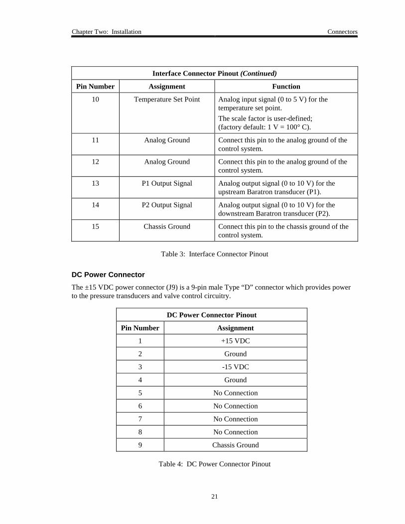
Interface Connector Pinout (Continued)
Pin Number Assignment Function
10 Temperature Set Point Analog input signal (0 to 5 V) for thetemperature set point.The scale factor is user-defined;(factory default: 1 V = 100° C).
11 Analog Ground Connect this pin to the analog ground of thecontrol system.
12 Analog Ground Connect this pin to the analog ground of thecontrol system.
13 P1 Output Signal Analog output signal (0 to 10 V) for theupstream Baratron transducer (P1).
14 P2 Output Signal Analog output signal (0 to 10 V) for thedownstream Baratron transducer (P2).
15 Chassis Ground Connect this pin to the chassis ground of thecontrol system.
Table 3: Interface Connector Pinout
DC Power ConnectorThe ±15 VDC power connector (J9) is a 9-pin male Type “D” connector which provides powerto the pressure transducers and valve control circuitry.
DC Power Connector Pinout
Pin Number Assignment
1 +15 VDC
2 Ground
3 -15 VDC
4 Ground
5 No Connection
6 No Connection
7 No Connection
8 No Connection
9 Chassis Ground
Table 4: DC Power Connector Pinout

Connectors Chapter Two: Installation
22
AC Power ConnectorThe +24 VAC power connector is a 15-pin Type “D” connector which provides power to theheater. The pins are connected internally. All four pins (either pins 1, 3, 5, and 7, or 2, 4, 6, and8) must be used; using fewer than the four assigned pins may cause too high a current on anindividual pin.
AC Power Connector Pinout
Pin Number Assignment
1 +24 VAC
2 +24 V Return
3 +24 VAC
4 +24 V Return
5 +24 VAC
6 +24 V Return
7 +24 VAC
8 +24 V Return
9 No Connection
10 No Connection
11 No Connection
12 No Connection
13 No Connection
14 No Connection
15 Chassis Ground
Table 5: AC Power Connector Pinout

Chapter Two: Installation Start Up
23
Start Up
Warning Read and follow all safety messages listed in SafetyProcedures and Precautions, page 3, BEFORE attempting tooperate the 1153 unit. Failure to adhere to these messagescould result in injury to personnel.
To start up the 1153 MFC:
1. Ensure that all gas and electrical connections are made.
2. Thoroughly evacuate all gas lines to remove water adsorbed on the exposed areas.
3. Leak check the entire system.
4. Connect the cables and allow the system to warm up.
5. Clear the system reset bit (digital operation only).
When the unit is powered up, the reset bit (bit 0) in the system status byte is set to “1”,indicating that the system has been reset. You should clear this status flag by resettingthe value of the bit to “0”, using the RS-232 Status Reset “SR_” command. Resetting thebit to zero allows you to monitor whether the unit loses power or has been reset.
Refer to How To Clear the Reset Bit, page 71, for more information.
Start Up Chapter Two: Installation
24
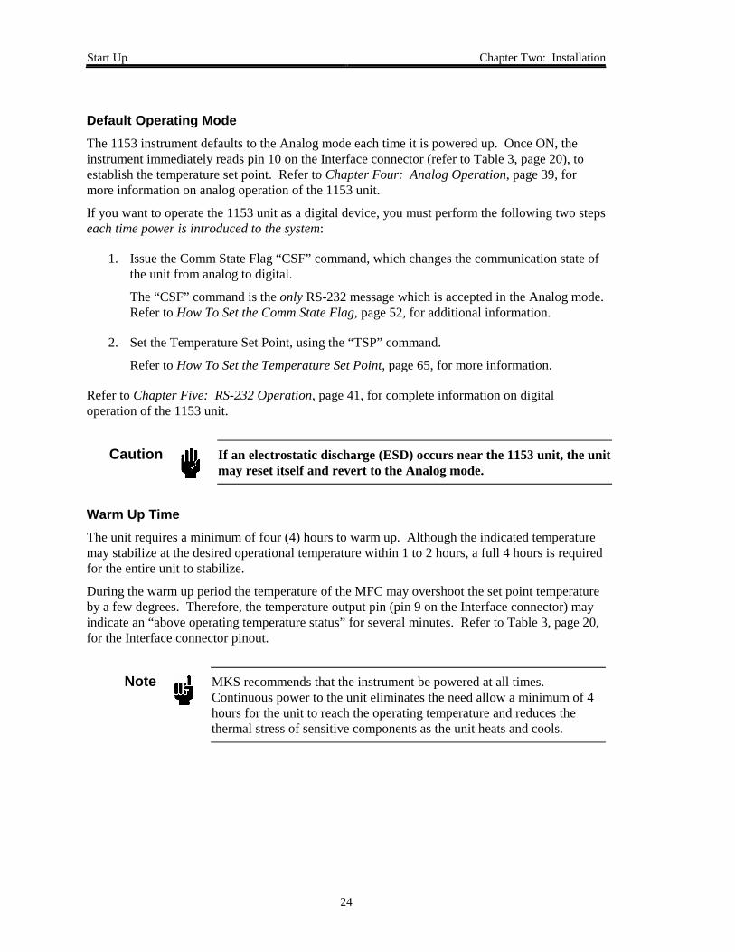
Default Operating ModeThe 1153 instrument defaults to the Analog mode each time it is powered up. Once ON, theinstrument immediately reads pin 10 on the Interface connector (refer to Table 3, page 20), toestablish the temperature set point. Refer to Chapter Four: Analog Operation, page 39, formore information on analog operation of the 1153 unit.
If you want to operate the 1153 unit as a digital device, you must perform the following two stepseach time power is introduced to the system:
1. Issue the Comm State Flag “CSF” command, which changes the communication state ofthe unit from analog to digital.
The “CSF” command is the only RS-232 message which is accepted in the Analog mode.Refer to How To Set the Comm State Flag, page 52, for additional information.
2. Set the Temperature Set Point, using the “TSP” command.
Refer to How To Set the Temperature Set Point, page 65, for more information.
Refer to Chapter Five: RS-232 Operation, page 41, for complete information on digitaloperation of the 1153 unit.
Caution If an electrostatic discharge (ESD) occurs near the 1153 unit, the unitmay reset itself and revert to the Analog mode.
Warm Up TimeThe unit requires a minimum of four (4) hours to warm up. Although the indicated temperaturemay stabilize at the desired operational temperature within 1 to 2 hours, a full 4 hours is requiredfor the entire unit to stabilize.
During the warm up period the temperature of the MFC may overshoot the set point temperatureby a few degrees. Therefore, the temperature output pin (pin 9 on the Interface connector) mayindicate an “above operating temperature status” for several minutes. Refer to Table 3, page 20,for the Interface connector pinout.
Note MKS recommends that the instrument be powered at all times.Continuous power to the unit eliminates the need allow a minimum of 4hours for the unit to reach the operating temperature and reduces thethermal stress of sensitive components as the unit heats and cools.

Chapter Two: Installation Start Up
25
Status LEDTo provide operation status, the 1153 unit is equipped with an internal LED, which is visiblethrough the vent holes on the rear instrument panel (refer to Figure 6, page 18). When the unit isfunctioning properly the LED flashes green, approximately once a second. If the CPU detects anerror (such as an over temperature error), the LED flashes red. If the CPU stops functioning, theLED stops flashing and may remain either on or off.
System Status LED Indicator
LED State Meaning
Flashing Green System functioning normally
Flashing Red Error detected by CPU
Solid Green or Red CPU not functioning
OFF CPU not functioning; system powered down
Table 6: System Status LED Indicator
Note If an error is detected by the CPU causing the LED to flash RED, it willcontinue flashing red even after if the error is corrected. You must cyclepower to the unit off and on to reset the LED to flashing green.

Start Up Chapter Two: Installation
26
This page intentionally left blank.

Chapter Three: Overview Functional Description
27
Chapter Three: Overview
Functional Description
The operation of the 1153 system is based on flow equations for a compressible gas across anorifice. Two pressure transducers of appropriate range measure these pressures; the CPUcalculates the resulting flow rates and generates an output voltage which is appropriately scaledto give a 0 to 5 VDC output equal to 0 to 100% FS flow of the specified material. The outputsignal and the set point signal are compared by the CPU using a Proportional-Integral (PI)control algorithm. An error signal (the difference between the set point signal and the actualsignal) is generated, and after further control calculations, a drive current for the proportioningflow control valve is generated which opens the valve to the correct position for the desired flowrate.
The stability and accuracy of the delivery system depends heavily on the proper integration of the1153 MFC, the power supply, the source heater, and the source feed lines.
Mass Flow Measurement Theory
Sonic, or choked-viscous, flow is obtained when the ratio of the upstream to downstreampressures across an orifice is greater than some critical value. For ideal gases with constantspecific heats, this critical pressure ratio is given by:
PP
kcritical
kk1
2
112
�
��
�
�� = +�
��
���
−
where: P1 = absolute pressure immediately upstream of the orificeP2 = absolute pressure immediately downstream of the orificek = ratio of specific heats for the gas

Mass Flow Measurement Theory Chapter Three: Overview
28
For most gases this critical pressure ratio is approximately equal to 2. Therefore, if the upstreampressure is at least twice the downstream pressure, the flow is sonic. For sonic flow, the massflow rate is independent of the downstream pressure and is directly proportional to the upstreampressure:
q CAPMT
f k= ×11 ( )
where: q = mass flow rate (sccm)C = discharge coefficient (a function of the nozzle geometry and other factors)A = area of the orifice openingM = molecular weight of the gasT = absolute temperature of the gas, K, or R
When the pressure ratio is less than the critical ratio, the flow is non-choked, and the mass flowrate becomes a function of downstream pressure. Specifically:
q CAPMT
f kPP
= �
��
�
��1
1
2
1 ,
The gas properties (M and k) as well as the nozzle diameter (for calculating the area) are enteredusing RS-232 commands and are stored in permanent memory (EEPROM). When the unit iscalibrated before shipping, the values of the experimentally determined discharge coefficient areentered and stored in the EEPROM. During operation, the CPU monitors the temperature andthe upstream and downstream pressures, determines whether the flow is choked or not, and thenuses the appropriate flow equation for calculating the mass flow rate across the orifice.
Note For improved performance near zero flow conditions, the calculated flowrate is set to zero if the pressure ratio (P2/P1) exceeds 0.9975.

Chapter Three: Overview Proportional - Integral (PI) Control Theory
29
Proportional - Integral (PI) Control Theory
The calculated flow rate is compared to the flow set point, and the error between the two isdetermined. The PI control algorithm updates the signal to the valve based on the error asfollows:
1. PROPORTIONAL control gives a valve signal (current) that is proportional to the error.
2. INTEGRAL control gives a valve response that is proportional to the integral of the errorwith respect to time.
The 1153 control algorithm combines the integral and proportional control adjustments into thevalve control parameter G (Gain). An additional multiplier for the proportional adjustment isincluded with the valve control parameter E (Phase Lead). The parameter E allows the controllerto compensate for the lag in the control system. In the case of the 1153 MFC, this lag is causedby restrictions in the gas flow path and the pressurized volume between the valve and floworifice.
The control parameters E and G are set at the factory for optimal system response. The typicalvalues of E are between 0 and 0.2 seconds. The values of G vary more for different applications,but are typically between 0.1 and 10. The response behavior is a relatively weak function of theparameter E in that the optimal value of E does not vary much for different flow conditions.
The response is a stronger function of the gain G. The optimal value of G is a function of the gasbeing used, the inlet pressure, and the temperature. To a first order approximation:
GP
MTinlet
~ 1
Therefore, if switching to a gas with a different molecular weight or changing the inlet pressure,the gain should be modified as appropriate. In general, if the observed flow response becomesunstable and the valve starts to oscillate, try reducing the gain. If the flow response is too slow,try increasing the gain. Refer to How To Set the Valve Control Parameters, page 56, for moreinformation.

Proportional - Integral (PI) Control Theory Chapter Three: Overview
30
To help speed the response of the 1153 unit, information regarding the flow rate versus valvecurrent is supplied to the CPU during calibration. A typical curve of flow rate versus valvecurrent is shown as the solid line in Figure 7.
0 10 20 30 40 50 60 70 80 90 100 110 120 130 140 150
Valve Current, mA
0
1
2
3
4
5
6
7
8
9
10
11
12
13
Flow
Rat
e, s
ccm
(Imin,Cvmin)
(Imax,Cvmax)
Figure 7: Flow Rate Versus Valve Current
As the current is increased from zero, there is a long region where no flow is observed. In thisregion, the valve current is overcoming the preload force tending to keep the valve closed. Oncethe magnetic forces balance this preload, the flow increases as the current is further increased.At some point, the magnetic force becomes so great that the valve snaps open and no furtherincrease in the flow rate occurs.
The dashed line shows how the actual curve is approximated by the CPU. The point where thevalve pops full open is approximated by the point (Imax, Cvmax) where Imax is the current in mAand Cvmax is an estimate of the maximum conductance of the valve in liters/sec (the maximumconductance is a measure of the maximum obtainable flow rate through the valve). The pointwhere the valve first opens is approximated by the point Imin, Cvmin). In this case, Cvmin istypically set to Cvmax/100. When the flow controller determines the valve current required toobtain a given flow set point, it will attempt to use a current between Imin and Imax. This helps tospeed the response of the MFC because currents between 0 and Imin are skipped over.
Chapter Three: Overview Proportional - Integral (PI) Control Theory
31
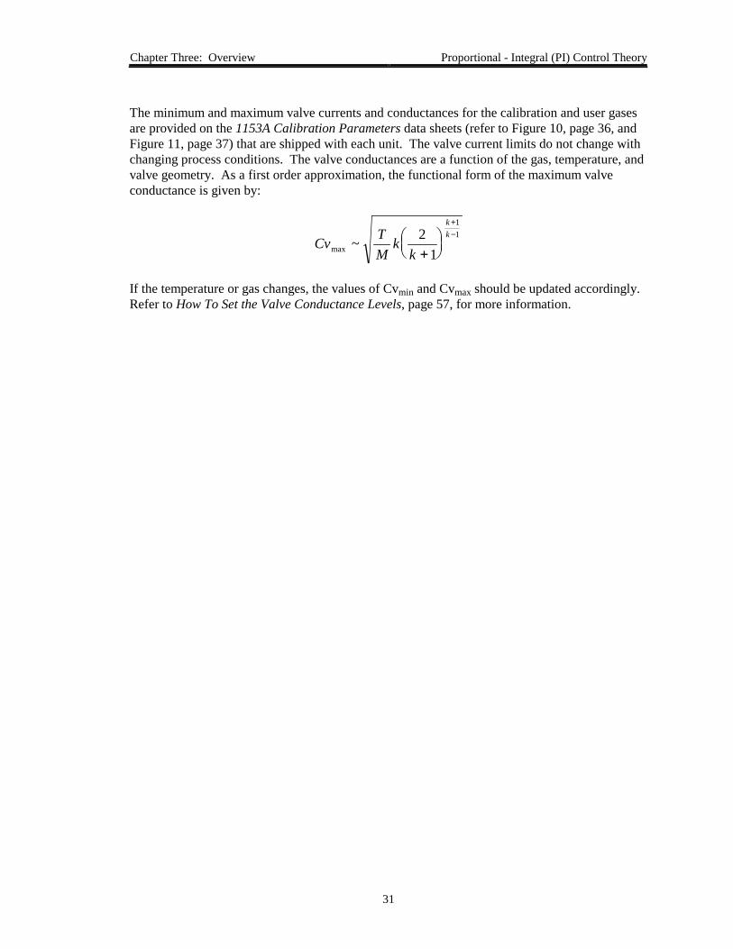
The minimum and maximum valve currents and conductances for the calibration and user gasesare provided on the 1153A Calibration Parameters data sheets (refer to Figure 10, page 36, andFigure 11, page 37) that are shipped with each unit. The valve current limits do not change withchanging process conditions. The valve conductances are a function of the gas, temperature, andvalve geometry. As a first order approximation, the functional form of the maximum valveconductance is given by:
Cv TM
kk
kk
max ~ 21
11
+���
���
+−
If the temperature or gas changes, the values of Cvmin and Cvmax should be updated accordingly.Refer to How To Set the Valve Conductance Levels, page 57, for more information.

Valve Orifice Size Chapter Three: Overview
32
Valve Orifice Size
The 1153 controller is available in nine valve orifice sizes. The valve orifice, combined with thesonic nozzle, establishes the pressure drop across the instrument. The valve orifice and nozzleare sized according to the process parameters provided to MKS when you ordered the 1153 unit.If your process parameters vary from the original parameters, it may be necessary to change thevalve orifice size. Consult the MKS Applications Department for assistance.
Note The orifice is not adjustable and is only replaceable at the factory.
Flow Control Range
The flow control range of the 1153 controller varies, depending upon the upstream pressure (P1)and downstream pressure (P2) of the application. Figure 8, shows the general effect ofdownstream pressure on the control range. When the system has no downstream pressure(P2 = 0), the ideal flow versus upstream pressure is linear over the entire flow range. When thedownstream pressure is greater than 0, the flow decreases to zero when the upstream pressureequals the downstream pressure.
The flow versus upstream pressure becomes steep as P1 approaches P2. Consequently, itbecomes more difficult to accurately control. For typical applications a control range of at least10% to 100% of full scale is achievable. Consult the MKS Applications Department for datarelative to your specific operating conditions.
0.0 0.5 1.0 1.5 2.0 2.5 3.0 3.5 4.0 4.5 5.00
30
60
90
120
150
180
1153 Set Point (P2 = 2 Torr)
Actual Flow (P2 = 2 Torr)
1153 Set Point (P2 = 3 Torr)
Actual Flow (P2 = 3 Torr)
1153 Set Point (P2 = 4 Torr)
Actual Flow (P2 = 4 Torr)
P1 (Torr)
Flo
w R
ate
(scc
m)
Figure 8: Typical Effects of Downstream Pressure (P2) on the Control Range

Chapter Three: Overview Calibration
33
Calibration
Each 1153 unit is calibrated at its normal operating temperature, using the process parametersspecified during the ordering process. The data collected during the calibration is transformedinto calibration constants which are fed back into the 1153 unit, and stored in memory for use bythe CPU. The pressure transducers are checked for linearity and repeatability, and adjusted asnecessary.
Note The 1153 unit is calibrated at the temperature and process pressurespecified at the time it was ordered. If the flow conditions (operatingtemperature, inlet pressure, or process gas) must change, contact theMKS Applications Department for information on updating thecalibration data.
The customer specified process pressure is maintained at the outlet of the instrument. The vaporpressure of the source material is simulated at the inlet port, and the equivalent N2 flow rates foreach of the cardinal set points (10%, 20%, ...100% FS) are put through the unit. Calibrationconstants are generated for each of these set points and stored in memory for use by the CPU.Refer to How To Setup the Calibration Constant Table, page 61, for instructions on how to enterthe calibration point information.

Calibration Chapter Three: Overview
34
Calibration Data SheetEach 1153 system is shipped with a Calibration Data Sheet, shown in Figure 9, which containsimportant information on the specific application for which your unit was designed.
1153A FINAL CALIBRATION DATACUSTOMER:
SERIAL #:
GAS: Mercury (Hg)
CALIBRATION GAS: Nitrogen
DATE: 03/26/97
MODEL: 1153A-2xxx
SP:
OPERATINGTEMPERATURE: 200°C
10
20
MFC STD:
Inlet Pressure: 8 Torr
Outlet Pres.: 2 Torr
Flow Set Point(%)
Cal Gas Set Point
(sccm)P1
(Torr)P2
(Torr)
Actual Flow Rate
(sccm)
30
40
50
60
70
80
90
100
12.5
25.0
37.5
50.0
62.5
75.0
87.5
100.0
112.5
125.0
2.123
2.416
2.831
3.334
3.916
4.528
5.139
5.756
6.360
6.975
12.6
24.8
37.4
50.2
62.5
74.9
87.3
100.1
112.5
125.1
2.008
2.017
2.025
2.033
2.041
2.049
2.057
2.065
2.073
2.081
Std. S/N:
Source Temp.: 180°C
Checked By:
Figure 9: Example Calibration Data Sheet

Chapter Three: Overview Calibration
35
Calibration ParametersThe embedded calibration (control) parameters which define a specific application are listed ontwo 1153A Calibration Parameters data sheets that are shipped with each 1153 unit. These datasheets (shown in Figure 10, page 36, and Figure 11, page 37), list the control parameters for thecalibration gas (typically nitrogen) and the user gas.
For all applications, a computer modeling program developed by MKS is used to help configurethe 1153 unit to best suit the process parameters. In the following example, a fictitious 1153 unitconfiguration will be defined to show how a typical application is developed. In our example,nitrogen (N2) is used as the calibration gas, and the user gas is mercury (Hg).
Our fictitious 1153 unit is designed for flowing 50 sccm mercury (Hg) at a temperature of200° C. The source temperature for the Hg is 180° C, where the vapor pressure is about 8 Torr.For this design, the modeling program selected the largest valve orifice and a 0.064 inch nozzlediameter. The unit was calibrated at the factory with N2 with an equivalent flow rate ofapproximately 125 sccm. The discharge coefficients were measured for N2 at each of thecardinal set points and they were estimated for Hg based on the results for N2 and the differencesbetween N2 and Hg.
Note 1. The data used in the example commands in Chapter Five: RS-232Operation, page 41, and in Appendix C: Application SpecificParameters, page 87, are based on the calibration parameters shownin Figure 10, page 36, and Figure 11, page 37.
2. In the examples, we assume that the user gas (Hg) values arecurrently stored in the 1153 unit and that the user wants to switch tothe calibration gas (N2) values. Therefore, in the example queries theresponse data will be values for Hg and in the example commands thedata sent will be for N2.

Calibration Chapter Three: Overview
36
MKS Instruments1153A Calibration Parameters
Serial Number Sample Configuration Gas used Mercury (Hg)
Gas Properties:Molecular Weight, M (gr/mol) 200.6 Ratio of Specific Heats, K 1.67
Flow Control:Max. Valve Current (mA) 117 Max. Valve Conductance (l/s) 0.42Min. Valve Current (mA) 68 Min. Valve Conductance (l/s) 0.0042
Analog FS Range (sccm/5 V) 50 Valve Control Parameter E 0.13Valve Control Parameter G 1.67
Communication Parameters:Baud Rate 9600 Unit’s Address (ID) 254
Temperature Control:Temperature Set Point (° C) 200 Temp. Control Parameter E 900Analog FS Temp. Range (° C/5 V)) 500 Temp. Control Parameter G 0.01Max. Temperature (° C) 205
1153 Design:Nozzle Diameter (in.) 0.064 Flow Set Point (sccm) 50Upstream Baratron (P1) Downstream Baratron (P2)
Range (Torr) 10 Range (Torr) 10Gain 1 Gain 1Offset 0 Offset 0
Discharge Coefficients versus Flow Rate:100% Flow Rate (sccm) 50
0% 0.585 60% 0.71310% 0.585 70% 0.73020% 0.615 80% 0.74230% 0.643 90% 0.75340% 0.669 100% 0.76150% 0.692
Figure 10: Example Calibration Parameter Data Sheet - User Gas

Chapter Three: Overview Calibration
37
MKS Instruments1153A Calibration Parameters
Serial Number Sample Configuration Gas used Nitrogen
Gas Properties:Molecular Weight, M (gr/mol) 28 Ratio of Specific Heats, K 1.39
Flow Control:Max. Valve Current (mA) 117 Max. Valve Conductance (l/s) 1.05Min. Valve Current (mA) 68 Min. Valve Conductance (l/s) 0.0105
Analog FS Range (sccm/5 V) 125 Valve Control Parameter E 0.01Valve Control Parameter G 0.67
Communication Parameters:Baud Rate 9600 Unit’s Address (ID) 254
Temperature Control:Temperature Set Point (° C) 200 Temp. Control Parameter E 900Analog FS Temp. Range (° C/5 V)) 500 Temp. Control Parameter G 0.01Max. Temperature (° C) 205
1153 Design:Nozzle Diameter (in.) 0.064 Flow Set Point (sccm) 125Upstream Baratron (P1) Downstream Baratron (P2)
Range (Torr) 10 Range (Torr) 10Gain 1 Gain 1Offset 0 Offset 0
Discharge Coefficients versus Flow Rate:100% Flow Rate (sccm) 125
0% 0.524 60% 0.68610% 0.524 70% 0.70520% 0.562 80% 0.72030% 0.597 90% 0.73240% 0.631 100% 0.74250% 0.661
Figure 11: Example Calibration Parameter Data Sheet - Calibration Gas

Labels Chapter Three: Overview
38
Labels
Warning LabelThe warning label, located on the rear panel of the unit (refer to Figure 6, page 18), lists thefactory set operating temperature for your application.
Factory SetOperatingTemperature
Figure 12: Warning Label
Serial Number LabelThe serial number label, located below the connectors on the side panel of the unit (refer toFigure 2, page 12), lists the unit’s serial and model numbers.
1153A-2XXX
Serial #:
Model #:
123456789
MKS Instruments, Inc. Made in the USA
Figure 13: Serial Number Label
The instrument is identified as “1153A-2XXX”, where:
1153A = Product Type
2XXX = Configuration
Refer to Appendix B: Model Code Explanation, page 85, for more information.

Chapter Four: Analog Operation General Information
39
Chapter Four: Analog Operation
General Information
Analog control of the 1153 unit is accomplished through the 15-pin Type “D” Interfaceconnector, located on the side panel of the instrument (refer to Figure 2, page 12). Refer to Table3, page 20, for the Interface connector pinout.
Note The temperature and flow set points, and the type of valve control can beset through the Interface connector. All other control parameters must beset using digital RS-232 commands.
The 1153 instrument defaults to the Analog mode when it is powered up. A full 4 hours isrequired for the entire unit to warm up and stabilize. Refer to Warm Up Time, page 24, foradditional information. Once the unit is ON, the instrument immediately reads pin 10 on theInterface connector to establish the temperature set point. The CPU then compares the currenttemperature to the set point and adjusts the power supplied to the heaters to reach and maintainthe set point.
When you use the MFC as an analog device, the only RS-232 command which is accepted is theComm State Flag “CSF” command, which allows you to change the communication state fromanalog to digital. All other RS-232 commands will return an Invalid Operating Mode errormessage; however, all RS-232 requests will be accepted. Refer to Chapter Five: RS-232Operation, page 41, for more information on digital operation.
How To Set the Temperature Set Point
To set the temperature set point, apply a voltage from 0 to 5V to pin 10 on the Interfaceconnector. The factory set scale factor is 1 V = 100° C.
Refer to How To Set the Temperature Set Point, page 65, for information on changing thetemperature set point with a RS-232 command.

How To Set the Flow Set Point Chapter Four: Analog Operation
40
How To Set the Flow Set Point
To set the flow set point in sccm, apply a voltage from 0 to 5V to pin 8 on the Interfaceconnector. The factory set scale factor is 1 V = 100° C.
Refer to How To Set the Flow Set Point, page 64, for information on changing the flow set pointwith a RS-232 command.
How To Control the Operation of the Valve
Pins 3, 4, and 8 on the Interface connector control the operation of the valve inside of the 1153unit. Pin 4 controls whether the unit will use direct valve control (set with Pin 3) or whether theunit will control the valve based on the flow set point (set with Pin 8). The digital control signalis user supplied.
Refer to How To Control the Operation of the Valve, page 67, for information on changing thevalve control using RS-232 commands.
How To Open the ValveTo open the valve:
1. Set Pin 4 LOW.
Pin 8 is ignored.
2. Set Pin 3 HIGH.
How To Close the ValveTo close the valve:
1. Set Pin 4 LOW.
Pin 8 is ignored.
2. Set Pin 3 LOW.
How To Set the Valve to Control to the Flow Set PointTo control the valve position based on the flow set point:
1. Set Pin 4 HIGH.
Pin 3 is ignored.

Chapter Five: RS-232 Operation General Information
41
Chapter Five: RS-232 Operation
General Information
Digital control of the 1153 unit is accomplished through the 9-pin RS-232 Serial Interfaceconnector, located on the side panel of the instrument (refer to Figure 2, page 12).
The 1153 instrument defaults to the Analog mode each time it is powered up. To use the MFC asa digital device you must ensure that the communication state is set to the Digital mode, and thatthe temperature set point is established, as described in Start Up, page 23.
Warning Read and follow all safety messages listed in SafetyProcedures and Precautions, page 3, BEFORE attempting tooperate the 1153 unit. Failure to adhere to these messagescould result in injury to personnel.
The digital RS-232 communication commands are separated into 3 functional groups: Setup,Control, and Informational. Use the Setup messages to review and adjust the operatingparameters including the system’s full scale flow, system temperature, flow constants, and setupof the calibration constant table. Use the Control messages to set the flow and temperature setpoints, and to control the temperature controller and valve position. Use the Informationalmessages to report the system flow, temperature, and pressure, as well as to query some of thenon-adjustable system features.
An additional group of RS-232 commands, set and optimized by the factory for your specificapplication, are described in Appendix C: Application Specific Parameters, page 87.

General Information Chapter Five: RS-232 Operation
42
RS-232 Communication ParametersThe RS-232 interface supports 1,200; 2,400; 4,800, and 9,600 baud. The RS-232communications parameters listed in Table 7 are factory set and, except for the baud rate, cannotbe adjusted.
RS-232 Communication Parameters
Parameter Value
Start Bit 1
Data Bits 8
Parity No parity
Stop Bit 1
Baud Rate* 1,200; 2,400; 4,800,9,600 (initial)
End-of-Line Delimiter semicolon (;)
* User-adjustable
Table 7: RS-232 Communication Parameters

Chapter Five: RS-232 Operation RS-232 Protocol
43
RS-232 Protocol
All RS-232 messages used by the mass flow controller are composed of variable length ASCIIstrings. Messages sent to the unit from a remote computer are either commands that instruct theinstrument to change an operating parameter, or requests that prompt the instrument to reportinformation. Messages sent by the unit to a remote computer, are responses. Responses eitheracknowledge a command issued by the host computer, or reply to a request sent by the hostcomputer.
Message SyntaxThe RS-232 message syntax uses the following conventions:
Note Spaces and commas are included in the syntax for clarity only. Do notinclude spaces or commas in actual commands, unless specifically noted.
bold Messages that you must enter exactly as shown in the manual. Do not includeany spaces or commas in the message string, unless specifically noted.
italics Placeholder that represents text or numeric values that you must supply.
response Format of message sent from the mass flow controller.
; Represents the end-of-line delimiter or termination character (specified inyour communications software). All messages must use a semicolon (;) as thetermination character.

RS-232 Protocol Chapter Five: RS-232 Operation
44
Commands and RequestsEvery message sent from a remote computer to the mass flow controller must include thefollowing information:
@@@ 254 TOF ! ; 20
Start of Message Characters
(1 minimum)
DeviceAddress
Command or Request
TerminatingSemicolon
Checksum
Figure 14: Example Command Message
Start of MessageCharacter “@”: At least 1 start of message character is required for the unit to recognize
that a message is being sent. Typically, 1 to 3 start of messagecharacters are used.
Device Address: A 3 digit device address (001, 002, and so forth through 253) thatidentifies the individual unit.
Command/Request: A series of three characters that identify the function.
Commands instruct the instrument to change an operating parameter.The command string is followed by an exclamation mark “!” and a datavariable field (if relevant).
Requests prompt the instrument to report information. The commandstring is followed by a question mark “?” and a data variable field (ifrelevant).
TerminatingSemicolon “;”: Represents the end-of-line delimiter or termination character.
Command orRequest Checksum: The sum of the ASCII values of the characters in the message from the
last start of message character, up to and including the terminatingsemicolon, truncated to a hexadecimal integer (two characters). Refer toFigure 15, page 45, for an example of how the checksum is calculated.

Chapter Five: RS-232 Operation RS-232 Protocol
45
How To Calculate the Command or Request Checksum
The checksum in a command or request message is calculated from the sum of the ASCII valuesof the characters in the message from the last start of message character “@”, up to and includingthe terminating semicolon (refer to Figure 15), using a standard ASCII value chart (refer to Table17, page 101).
The checksum is the decimal sum of the ASCII values, converted to a hexadecimal value andtruncated to its last 2 characters.
@@ @ 20
Checksum calculated fromthese characters
254 TOF! ;
Figure 15: ASCII Characters in a Command Message Used to Calculate the Checksum
For example, the checksum value of “20” shown in Figure 15 was calculated as follows:
CHARACTER ASCII CODE (decimal)
@ 642 505 534 52T 84O 79F 70! 33; 59
Sum = 544 (decimal)
= 220 (hexadecimal)
Checksum Value = 20** hexadecimal sum truncated to the last 2 characters
Note 1. You must include a checksum value with every command and requestmessage sent to the mass flow controller. The acceptable checksumvalues range from 00 to FF.
2. You can instruct the software to ignore the checksum by using thechecksum value “FF” in every message.

RS-232 Protocol Chapter Five: RS-232 Operation
46
How To Send a Command
A command message string consists of at least one start of message character “@”, followed bythe device address, a series of three characters “FNC” that identify the function, an exclamationmark “!” to identify the string as a command, a data variable field (if relevant), the terminatingsemicolon “;”, and the checksum.
@@@001FNC!data variable;Checksum
How To Send a Request
A request message string consists of at least one start of message character “@”, followed by thedevice address, a series of three characters “FNC” that identify the function, a question mark “?”to identify the string as a request, a data variable field (if relevant), the terminating semicolon“;”, and the checksum.
@@@001FNC?data variable;Checksum

Chapter Five: RS-232 Operation RS-232 Protocol
47
ResponsesEvery message sent from the mass flow controller to a remote computer includes the followinginformation:
@@@ 000 ACK ; FF
Start of MessageCharacters(always 3)
Response
TerminatingSemicolon
ChecksumDeviceAddress
Figure 16: Example Response Message
Start of MessageCharacter “@”: Three (3) start of message characters are always sent from the controller.
Device Address: The 3 digit address of the master device (always “000”).
Response: A literal “ACK” (acknowledged) or “NAK” (not acknowledged) with adata variable field (if relevant). The response either acknowledges acommand issued by the host computer, or replies to a request sent by thehost computer.
TerminatingSemicolon “;”: Represents the end-of-line delimiter or termination character.
Response Checksum: The 1153 unit does not calculate a checksum for its response strings. Inthe response message, the unit always returns a checksum value of “FF.”

RS-232 Protocol Chapter Five: RS-232 Operation
48
If a command or request is accepted and implemented, the response is the three start of messagecharacters “@@@”, followed by the address of the master device (always “000”), a literal“ACK” with a data variable field (if relevant), the terminating semicolon, and the checksumvalue of “FF.”
@@@000ACKdata variable;FF
If a command or request is either invalid or contained an error, the response is the three start ofmessage characters “@@@”, followed by the address of the master device (always “000”), aliteral “NAK” with an error code, the terminating semicolon, and the checksum value of “FF.”The error codes are listed in Table 8.
@@@000NAKerror code;FF
RS-232 Error Codes
Error Code Description
01 Checksum error
10 Syntax error
11 Data length error
12 Invalid data
13 Invalid operating mode
17 Invalid command
Table 8: RS-232 Error Codes
Chapter Five: RS-232 Operation RS-232 Protocol
49
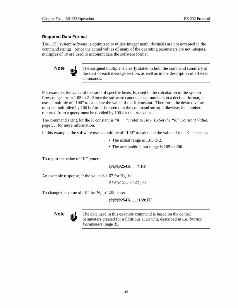
Required Data FormatThe 1153 system software is optimized to utilize integer math; decimals are not accepted in thecommand strings. Since the actual values of many of the operating parameters are not integers,multiples of 10 are used to accommodate the software format.
Note The assigned multiple is clearly stated in both the command summary atthe start of each message section, as well as in the description of affectedcommands.
For example; the value of the ratio of specific heats, K, used in the calculation of the systemflow, ranges from 1.05 to 2. Since the software cannot accept numbers in a decimal format, ituses a multiple of “100” to calculate the value of the K constant. Therefore, the desired valuemust be multiplied by 100 before it is entered in the command string. Likewise, the numberreported from a query must be divided by 100 for the true value.
The command string for the K constant is “K _ _”; refer to How To Set the “K” Constant Value,page 55, for more information.
In this example, the software uses a multiple of “100” to calculate the value of the “K” constant.
• The actual range is 1.05 to 2.• The acceptable input range is 105 to 200.
To report the value of “K”, enter:
@@@254K _ _?;FF
An example response, if the value is 1.67 for Hg, is:@@@000ACK167;FF
To change the value of “K” for N2 to 1.39, enter:
@@@254K _ _!139;FF
Note The data used in this example command is based on the controlparameters created for a fictitious 1153 unit, described in CalibrationParameters, page 35.

Setup Messages Chapter Five: RS-232 Operation
50
Setup Messages
The Setup messages enable you to configure the 1153 unit for operation by allowing you toreview and adjust various operating parameters. These messages can be sent as either commandsor queries, except where noted. Refer to Required Data Format, page 49, for information onusing the proper command string format.
Note 1. A device address of “254” and a checksum value of “FF” are used inthe example messages shown in this section.
2. Commas are included in the syntax for clarity only. Do not includecommas in actual commands, unless specifically noted.
RS-232 Setup Messages
Command Description Multiple Data Variables / Response
CC_ Baud Rate None Enter 1,200; 2,400; 4,800; 9,600.Initial setting is 9,600.
CSF Comm State Flag None Enter ANALOG or DIGITAL.Initial setting is ANALOG.
FSR Full Scale Range -Flow
10 Enter 1 to 4,000,000.Actual range is 0.1 to 400,000 sccm.Initial value is application dependent.
FST Full Scale Range -Temperature
None Enter 100 to 500.Initial value in ° C / 5 V is applicationdependent.
MXT MaximumTemperature
None Enter 0 to 210.Initial setting in ° C is applicationdependent.
K_ _ K Constant 100 Enter 105 to 200.Actual range is 1.05 to 2.Initial value is 1.1.
EV_ Valve ControlParameter E“Phase Lead”
100 Enter -32,000 to 32,000.Actual range is -320 to 320 seconds.Initial value is application dependent.
Table 9: RS-232 Setup Messages(Continued on next page)

Chapter Five: RS-232 Operation Setup Messages
51
RS-232 Setup Messages (Continued)
Command Description Multiple Data Variables / Response
GV_ Valve ControlParameter G“Gain”
100 Enter 1 to 32,000.Actual range is 0.01 to 320.Initial value is application dependent.
CVM Minimum ValveConductance (Cv)
100,000 Enter 1 to 500,000.Actual range is 0.00001 to 5 liter/sec(l/s).Initial value is application dependent.
CVX Maximum ValveConductance (Cv)
100,000 Enter 1 to 500,000.Actual range is 0.00001 to 5 liter/sec(l/s).Initial value is application dependent.
CIM Minimum ValveCurrent
100 Enter 0 to 15,000.Actual range is 0 to 150 mA.Initial setting is application dependent.
CIX Maximum ValveCurrent
100 Enter 0 to 15,000.Actual range is 0 to 150 mA.Initial setting is application dependent.
MM_ Molecular Weight 10 Enter 1 to 10,000.Actual range is 0.1 to 1,000 grams permole (g/mol).Initial value is application dependent.
FTR Full Scale FlowRange of theCalibration ConstantTable
10 Enter 1 to 4,000,000.Actual range is 0.1 to 400,000 sccm.Initial value is application dependent.
FCP Calibration ConstantTable
j = None
Value = 1,000
Enter “j, value”, where:
j = 0 to 10value = 1 to 2,000
Actual range is 0.001 to 2
SUD Save Current Datainto EEPROM
None None
RFD Reset the Variablesfrom the FactoryDefaults
None None
Table 9: RS-232 Setup Messages

Setup Messages Chapter Five: RS-232 Operation
52
How To Change the Baud RateThis command sets the baud rate of the communications protocol. The baud rate changes afterthis command is complete and the response message is sent. The baud rate can be set to 1,200;2,400; 4,800; or 9,600 (initial).
Note You must change the baud rate at both the instrument and the hostcomputer.
To check the baud rate, enter:@@@254CC_?;FF
An example response is:@@@000ACK9600;FF
To change the baud rate to 4,800, enter:
@@@254CC_!4800;FF
How To Set the Comm State FlagThe communication state flag defines the type of control to be used with your unit. The 1153instrument can be operated using analog control (initial) through the 15-pin Interface connector,or digital control through the 9-pin RS-232 Serial Interface connector.
Note 1. The 1153 unit always defaults to analog control, regardless of thestate of the comm state flag, when it is powered up.
2. Analog voltages (0 to 5 V) are always sent to the analog output port.
To query the status of the comm state flag, enter:
@@@254CSF?;FF
An example response is:@@@000ACKANALOG;FF
To change to digital control, enter:
@@@254CSF!DIGITAL;FF

Chapter Five: RS-232 Operation Setup Messages
53
How To Set the Full Scale Flow RangeThis function sets the volume of flow in standard cubic centimeters per minute (sccm) whichcorresponds to the full scale analog signal (5 V).
Note The software uses a multiple of “10” to calculate the value of the fullscale flow range.
• The actual full scale flow range is 0.1 to 400,000 sccm; the initialvalue is application dependent.
• The acceptable input range is 1 to 4,000,000.
To query the full scale flow range, enter:
@@@254FSR?;FF
An example response, if the flow rate for the user gas Hg is 50.0 sccm, is:@@@000ACK500;FF
To change the full scale flow range for the N2 calibration gas to 125 sccm, enter:
@@@254FSR!1250;FF
How To Set the Full Scale Temperature RangeThis function sets the full scale temperature range in degrees Celsius (° C) which corresponds tothe full scale analog signal (5 V). The factory set scale factor is 1 V = 100° C. The acceptabletemperature input range is 100° to 500° C / 5 V; the initial value is set so that 5 V = 500° C.
The initial value is set so that the voltage of the set point and the output give a direct reading oftemperature. Therefore, in the example application described in Calibration Parameters,page 35, 2.00 V = 200° C. The maximum temperature of the unit is 200° C.
To query the full scale temperature range, enter:
@@@254FST?;FF
An example response, if the temperature range is 500° C / 5 V, is:@@@000ACK500;FF
To change the full scale temperature range to 200° C / 5 V, enter:
@@@254FST!200;FF
Setup Messages Chapter Five: RS-232 Operation
54
How To Set the Maximum TemperatureAs a safety feature, the 1153 unit has a “Maximum Temperature” parameter, which sets themaximum temperature, in degrees Celsius (° C) within the 1153 enclosure.
If the temperature within the unit rises above the maximum temperature, the temperaturecontroller immediately turns off the power to the heaters and the internal status LED flashesRED. The LED will continue to flash RED, even after if the error is corrected, until the power tothe unit is cycled off and on. The power to the heaters can be restored by issuing the “TON”command (refer to How To Turn the Temperature Controller ON, page 66).
This feature is useful for vapors known to decompose above some temperature. Because thetemperature controller may have some overshoot when first approaching the temperature setpoint, the maximum temperature parameter should be set at least 5° C above the set point (referto How To Set the Temperature Set Point, page 65).
The acceptable range is 0° to 210° C. The initial setting is application dependent; a typical valueis 205° C.
To report the maximum temperature setting, enter:
@@@254MXT?;FF
An example response is:@@@000ACK205;FF
To change the temperature to 180° C, enter:
@@@254MXT!180;FF

Chapter Five: RS-232 Operation Setup Messages
55
How To Set the “K” Constant ValueThis function sets the value of the “K” constant, used in the flow calculation. This constant isgas dependent and represents the ratio of specific heats of the flowing gas.
Note The software uses a multiple of “100” to calculate the value of the “K”constant.
• The actual range is 1.05 to 2; the initial setting is applicationdependent.
• The acceptable input range is 105 to 200.
To report the value of “K”, enter:
@@@254K _ _?;FF
An example response, if the value is 1.67 for Hg, is:@@@000ACK167;FF
To change the value of “K” for N2 to 1.39, enter:
@@@254K _ _!139;FF

Setup Messages Chapter Five: RS-232 Operation
56
How To Set the Valve Control ParametersThese functions set the value of the valve control parameters E and G, used in the flow controlcalculations. These constants are described in detail in Proportional - Integral (PI) ControlTheory, page 29.
How To Set the Valve Control Parameter E (Phase Lead)
The valve control parameter E or phase lead, is set using the “EV_” command.
Note The software uses a multiple of “100” to calculate the value of “EV_.”• The actual range is -320 to 320 seconds; the initial setting is
optimized at the factory.• The acceptable input range is -32,000 to 32,000.
To report the value of “EV_”, enter:
@@@254EV_?;FF
An example response, if the value is 0.13 for Hg, is:@@@000ACK13;FF
To change the value of the “EV_” constant for N2 to 0.01, enter:
@@@254EV_!1;FF
How To Set the Valve Control Parameter G (Gain)
The valve control parameter G, or gain, is set using the “GV_” command.
Note The software uses a multiple of “100” to calculate the value of “GV_.”• The actual range is 0.01 to 320; the initial setting is optimized at the
factory.• The acceptable input range is 1 to 32,000.
To report the value of “GV_”, enter:@@@254GV_?;FF
An example response, if the value is 1.67 for Hg, is:@@@000ACK167;FF
To change the value of the “GV_” constant for N2 to 0.67, enter:
@@@254GV_!67;FF

Chapter Five: RS-232 Operation Setup Messages
57
How To Set the Valve Conductance LevelsThese functions set the minimum and maximum valve conductance levels, in liters per second(l/s), used in the flow calculation. These constants are described in detail in Proportional -Integral (PI) Control Theory, page 29.
Note The software uses a multiple of 100,000 to calculate the conductancevalues.
• The actual range is 0.00001 to 5 l/s; the initial value is applicationdependent.
• The acceptable input range is 1 to 500,000.
How To Set the Minimum Valve Conductance
To query the minimum valve conductance value, enter:
@@@254CVM?;FF
An example response, if the minimum valve conductance rate is 0.0042 l/s, is:@@@000ACK420;FF
To change the minimum valve conductance rate to 0.0105 l/s, enter:
@@@254CVM!1050;FF
How To Set the Maximum Valve Conductance
To query the maximum valve conductance value, enter:
@@@254CVX?;FF
An example response, if the maximum valve conductance rate is 0.42 l/s, is:@@@000ACK42000;FF
To change the maximum valve conductance rate to 1.05 l/s, enter:
@@@254CVX!105000;FF

Setup Messages Chapter Five: RS-232 Operation
58
How To Set the Valve Current LevelsThese functions set the minimum and maximum valve current values. These constants aredescribed in detail in Proportional - Integral (PI) Control Theory, page 29.
Note The valve current values are optimized at the factory and should not beadjusted without consulting MKS Instruments.
Note The software uses a multiple of “100” to calculate the valve currentvalues.
• The actual range is 0 to 150 milliamperes (mA); the initial value isapplication dependent.
• The acceptable input range is 0 to 15,000.
How To Set the Minimum Valve Current
To query the value of the minimum valve current, enter:
@@@254CIM?;FF
An example response, if the minimum current value is 68 mA, is:@@@000ACK6800;FF
To change the minimum current value to 50 mA, enter:
@@@254CIM!5000;FF
How To Set the Maximum Valve Current
To query the value of the maximum valve current, enter:
@@@254CIX?;FF
An example response, if the maximum current value is 117 mA, is:@@@000ACK11700;FF
To change the current value to 100 mA, enter:
@@@254CIX!10000;FF

Chapter Five: RS-232 Operation Setup Messages
59
How To Set the Molecular WeightThis function identifies the molecular weight of the gas being monitored.
Note The software uses a multiple of “10” to calculate the value of themolecular weight.
• The actual range is 0.1 to 1,000 grams per mole (g/mol); the initialvalue is application dependent.
• The acceptable input range is 1 to 10,000.
To report the molecular weight, enter:
@@@254MM_?;FF
An example response, if the molecular weight for Hg is 200.6 g/mol, is:@@@000ACK2006;FF
To change the molecular weight to 28 for N2, enter:
@@@254MM_!280;FF
Setup Messages Chapter Five: RS-232 Operation
60
How To Set the Full Range of the Calibration Constant TableThis command sets the full scale flow range of the Calibration Constant Table.
This function allows you to change the full scale flow range of the unit (set with the “FSR”command, refer to How To Set the Full Scale Flow Range, page 53) without having to update theentire Calibration Constant Table for the new range.
Note The software uses a multiple of “10” to calculate the value of the fullscale flow of the Calibration Table.
• The actual full scale flow range is 0.1 to 400,000 sccm; the initialvalue is application dependent.
• The acceptable input range is 1 to 4,000,000.
To query the full scale range of the calibration table, enter:
@@@254FTR?;FF
An example response, if the full scale range of the Hg gas calibration table is 50 sccm, is:@@@000ACK500;FF
To change the full scale range of the N2 gas calibration table to 125 sccm, enter:
@@@254FTR!1250;FF

Chapter Five: RS-232 Operation Setup Messages
61
How To Setup the Calibration Constant TableThe “FCP” command allows you to enter the calibration constants for each of the cardinal setpoints (10%, 20%, ..., 100% of full scale flow rate). The “FTR” command, defined in How ToSet the Full Range of the Calibration Constant Table, page 60, is used to enter the full scale flowrate (in sccm) that corresponds to the 100% point in the calibration table.
Note The initial values for the calibration constants in this table are determinedduring flow calibration and are provided on the Calibration Data Sheetsupplied with the 1153 unit (refer to Figure 9, page 34).
The query for this function is formatted as:
@@@254FCP?j;FF
The variable “j” specifies the data point being referred to (for example, j = 0 for the 0% point,j = 1 for the 10% point, j = 10 for the 100% point).
The command for this function is formatted as:
@@@254FCP!j,value;FF
The variable “value” specifies the calibration gas flow for the specified data point “j”, in sccm.A comma is required between the variable “j” and its value.
Note The software does not use a multiple for the value of “j.”A multiple of “1,000” is used to calculate the value of each calibrationpoint.
• The actual and acceptable input range for “j”, is 0 to 10.• The actual range for the value is 0.001 to 2, with an initial value of 1.• The acceptable input range for the value is 1 to 2,000.
To query the value of the calibration point at the 10% FS flow point for Hg, enter:
@@@254FCP?1;FF
An example response, if the value of the 10% FS flow point for Hg is 0.585, is:@@@000ACK1,585;FF
To change the value of the calibration point at the 10% FS flow point for N2 to 0.524, enter:
@@@254FCP!1,524;FF

Setup Messages Chapter Five: RS-232 Operation
62
How To Save Data to the EEPROMWhen parameters are changed using RS-232 commands (such as changing the molecular weightor changing the valve control parameters), they are stored in the 1153 unit’s temporary memory(RAM). If the unit is powered down, the changes are not saved.
The “SUD” command stores the current settings in permanent memory (EEPROM), so that theyare saved upon power down. There is no query associated with this function.
Note The flow and temperature set points must always be reset after theinstrument is powered up. Refer to How To Set the Flow Set Point, page64, and How To Set the Temperature Set Point, page 65, for moreinformation.
To save the current data to the EEPROM, enter:
@@@254SUD!;FF
How To Reset the Factory SettingsThis command resets all of the user-set parameters to the initial, factory settings. There is noquery associated with this function.
To reset the parameters, enter:@@@254RFD!;FF

Chapter Five: RS-232 Operation Control Messages
63
Control Messages
Use the Control messages to set the flow and temperature set points, and to control thetemperature controller and valve position. These messages can be sent as either commands orqueries, except where noted. Refer to Required Data Format, page 49, for information on usingthe proper command string format.
Note 1. A device address of “254” and a checksum value of “FF” are used inthe example messages shown in this section.
2. Commas are included in the syntax for clarity only. Do not includecommas in actual commands, unless specifically noted.
RS-232 Control Messages
Command Description Multiple Data Variables / Response
FSP Flow Set Point 1,000 Enter 0 to 400,000,000.Actual range is 0 to 400,000;no initial setting.
TSP Temperature SetPoint
100 Enter 0 to (Max Temp x 100).Actual range is 0 to Max Temp;no initial setting.
TOF TemperatureController OFF
None None
TON TemperatureController ON
None None
OPV Open Valve None None
CLV Close Valve None None
CTV Control Valve None None
Table 10: RS-232 Control Messages

Control Messages Chapter Five: RS-232 Operation
64
How To Set the Flow Set PointThe “FSP” command sets the flow set point in sccm. Note that when operating in the analogmode, the flow set point is taken from the 0 to 5 V input signal, measured from pin 8 on theInterface connector. Refer to Table 3, page 20, for the Interface connector pinout. For moreinformation on the analog control of the flow set point, refer to How To Set the Flow Set Point,page 40.
Note The software uses a multiple of “1,000” to calculate the value of the flowset point.
• The actual range is 0 to 400,000 sccm.• The acceptable input range is 0 to 400,000,000.
To query the flow set point, enter:
@@@254FSP?;FF
An example response, if the set point is 50 sccm, is:@@@000ACK50000;FF
To change the set point to 25 sccm, enter:
@@@254FSP!25000;FF

Chapter Five: RS-232 Operation Control Messages
65
How To Set the Temperature Set PointThe “TSP” command sets the temperature set point. Note that when operating in the analogmode, the temperature set point is taken from the 0 to 5 V input signal, measured from pin 10 onthe Interface connector. Refer to Table 3, page 20, for the Interface connector pinout. For moreinformation on the analog control of the temperature set point, refer to How To Set theTemperature Set Point, page 39.
Note The software uses a multiple of “100” to calculate the value of thetemperature set point.
• The actual range is 0 to Maximum Temperature (MXT).• The acceptable input range is 0 to (Maximum Temperature x 100).
Refer to How To Set the Maximum Temperature, page 54, for informationon setting the maximum temperature within the 1153 enclosure.
To query the temperature set point, enter:
@@@254TSP?;FF
An example response, if the set point is 200° C, is:@@@000ACK20000;FF
To change the set point to 190° C, enter:
@@@254TSP!19000;FF

Control Messages Chapter Five: RS-232 Operation
66
How To Turn the Temperature Controller OFFBy default, the temperature controller is ON. The CPU compares the actual unit temperature tothe set point and adjusts the power to the heaters as required. The “TOF” command turns thetemperature controller off, and shuts off power to the heater. There is no query associated withthis function.
To turn the controller off, enter:
@@@254TOF!;FF
How To Turn the Temperature Controller ONThe “TON” command turns the temperature controller ON and allows power to return to theheaters, after having been manually turned off with the “TOF” command, or automatically turnedoff because the temperature within the 1153 enclosure rose above the maximum temperature(refer to How To Set the Maximum Temperature, page 54, for more information). There is noquery associated with this function.
To turn the controller on, enter:
@@@254TON!;FF
Note If the power to the heaters was shut off because the temperature roseabove the maximum temperature, the status LED will continue to flashRED, even after if the error is corrected, until the power to the unit iscycled off and on.

Chapter Five: RS-232 Operation Control Messages
67
How To Control the Operation of the ValveThese commands control the operation of the valve inside of the 1153 unit. There are no queriesassociated with these functions. To query the type of valve operation, use the “VSF” command,as described in How To Report the Type of Valve Operation, page 74.
How To Open the Valve
The “OPV” command causes the maximum valve current, set with the “CIX” command (refer toHow To Set the Maximum Valve Current, page 58), to be sent to the valve.
To open the valve, enter:
@@@254OPV!;FF
Note The maximum valve current restriction can be overidden in the valveopen mode by using the “SIV” command (refer to How To Set the ValveCurrent, page 92). This may be useful when purging the system and notattempting to control flow.
How To Close the Valve
The “CLV” command causes zero current to be sent to the valve.
To close the valve, enter:@@@254CLV!;FF
How To Set the Valve to Control to the Flow Set Point
The “CTV” command instructs the CPU to control the valve position based on the flow set point(refer to How To Set the Flow Set Point, page 64).
To set the valve to flow control mode, enter:
@@@254CTV!;FF

Informational Messages Chapter Five: RS-232 Operation
68
Informational Messages
The Informational messages report data on the 1153 system, including system flow, temperature,and pressure. These messages, with the exception of the status reset command, can only be sentas queries. Refer to Required Data Format, page 49, for information on using the propercommand string format.
Note 1. A device address of “254” and a checksum value of “FF” are used inthe example messages shown in this section.
2. Commas are included in the syntax for clarity only. Do not includecommas in actual commands, unless specifically noted.
RS-232 Informational Messages
Command Description Multiple Response
T_ _ System Status None Indicates the state of the system.Refer to Table 12, page 70.
SR_ Status Reset None Clears the reset bit in the systemstatus byte.
VER Software Version None Reports the software version number.
CF_ Flow 1,000 Reports the current gas flow throughthe unit in sccm.Reported and actual flow values areapplication dependent.
CT_ Temperature 100 Reports the current temperature in theunit in degrees Celsius (° C).Reported range is 0 to 20,000.Actual range is 0 to 200° C.
RPA Pressure of UpstreamBaratron (P1)
1,000 Reports the pressure in Torr.Reported and actual pressure rangesare application dependent.
RPB Pressure ofDownstream Baratron(P2)
1,000 Reports the pressure in Torr.Reported and actual pressure rangesare application dependent.
VSF Valve State None Reports the position of the valve asOPEN, CLOSED, or CONTROL.
Table 11: RS-232 Informational Messages(Continued on next page)

Chapter Five: RS-232 Operation Informational Messages
69
RS-232 Informational Messages (Continued)
Command Description Multiple Response
RP_ Required Power 100 Reports the power required for theheater to maintain or reach the setpoint.Reported range is 0 to 20,000.Actual range is 0 to 200 Watts.
FCA DischargeCoefficient
1,000 Reports the value of the dischargecoefficient being used in the currentflow calculations.Reported range is 1 to 2,000.Actual range is 0.001 to 2.
VRF V reference 10,000 Reports the system voltage. Whenthe system is operating properly, thisvalue should be close to 5 Volts.
Table 11: RS-232 Informational Messages

Informational Messages Chapter Five: RS-232 Operation
70
How To Report the System StatusThe System Status command “T _ _” reports the value of the system status byte which containsinformation on the status of the 1153 system. The assignments and values for each bit are listedin Table 12.
The reported value is the sum of the individual status bit values that are set. Each bit is initiallyset low (value = 0), meaning the error condition does not exist. When an error condition isdetected, the appropriate bit is set high (to the bit value listed in Table 12).
System Status Byte
Bit Assignment Description Bit Value
0 Reset Indicates whether system has been reset. 1
1 Analog I/OCable Connect
Bit is set high if the cable is not connected. 2
2 Unused Bit is always set low. 4
3 EEPROM Bit is set high if there is any type ofEEPROM error either in reading data from orwriting data to the EEPROM.
8
4 RAM Bit is set high if there is any error in the RAM. 16
5 ROM Bit is set high if there is an error in the ROMchecksum. Checked during initialization.
32
6 Unused Bit is always set low. 64
7 Temperature Bit is set high if the indicated 1153temperature exceeds the MAX TEMP; theprocessor shuts off power to the heaters.
128
Table 12: System Status Byte

Chapter Five: RS-232 Operation Informational Messages
71
To query the system status, enter:
@@@254T_ _?;FF
An example response, if no error conditions exist, is:@@@000ACK0;FF
An example response, if there is an error in the EEPROM, is:@@@000ACK8;FF
An example response, if there are errors in both the EEPROM and the temperature controlsystem, is:
@@@000ACK136;FF
The status byte value of 136 represents the sum of the individual status bit values for theEEPROM (8) and temperature (128) control.
How To Clear the Reset BitThe Status Reset command clears the reset bit in the system status byte. There is no queryassociated with this function.
Note 1. The reset bit is the only bit in the status byte that can be reset using asoftware command. All other error conditions (refer to Table 12,page 70) must be corrected before the corresponding bit will becleared.
2. If you clear the reset bit after first powering up the unit, the reset bitcan then be monitored to see if power to the unit is later interrupted.
To send the status reset command, enter:
@@@254SR_!;FF
If an error occurs after the status flags are cleared, the flags are immediately reset.
How To Report the Software VersionThis query reports the version of software in your unit. There is no command associated withthis function.
To check the software version, enter:
@@@254VER?;FF
An example response is:@@@000ACKV1.00;FF

Informational Messages Chapter Five: RS-232 Operation
72
How To Report the Gas FlowThis query reports the current gas flow through your unit in sccm. There is no commandassociated with this function.
Note The software uses a multiple of “1,000” to calculate the flow.• The actual and reported flow ranges are application dependent.
To report the flow, enter:
@@@254CF_?;FF
An example response, if the flow is 50 sccm, is:@@@000ACK50000;FF
How To Report the TemperatureThis query reports the current temperature in degrees Celsius (° C) of the heated components(such as the valve and flow bodies) in the 1153 unit. There is no command associated with thisfunction.
Note The software uses a multiple of “100” to calculate the temperature in ° C.• The actual temperature range is 0 to 200° C.• The reported range is 0 to 20,000.
To report the temperature, enter:
@@@254CT_?;FF
An example response, if the temperature is 150° C, is:@@@000ACK15000;FF

Chapter Five: RS-232 Operation Informational Messages
73
How To Report the PressureThese queries report the current pressure in Torr, measured by the Baratrons inside of the 1153unit. There are no commands associated with these functions.
Note The software uses a multiple of “1,000” to calculate the pressure valuesfrom the two transducers, in Torr.
• The actual and reported pressure ranges are application dependent.
How To Report the Pressure of the Upstream Baratron (P1)
To report the pressure of the upstream Baratron, enter:
@@@254RPA?;FF
An example response, if the pressure is 6.45 Torr, is:@@@000ACK6450;FF
How To Report the Pressure of the Downstream Baratron (P2)
To report the pressure of the downstream Baratron, enter:
@@@254RPB?;FF
An example response, if the pressure is 2.004 Torr, is:@@@000ACK2004;FF

Informational Messages Chapter Five: RS-232 Operation
74
How To Report the Type of Valve OperationThis query reports the state of the valve as open, closed (initial), or control. There is nocommand associated with this function. The valve position is set using the “OPV”, “CLV”, and“CTV” commands, as described in How To Control the Operation of the Valve, page 67.
To query the position of the valve, enter:
@@@254VSF?;FF
An example response, is:@@@000ACKCLOSED;FF
How To Report the Power Required by the HeatersThis query reports the power required by the heaters to maintain or reach the desired temperatureset point. There is no command associated with this function.
Note The software uses a multiple of “100” to calculate the power value.• The actual power range is 0 to 200 Watts.• The reported range is 0 to 20,000.
To report the power, enter:
@@@254RP_?;FF
An example response, if the required power is 200 Watts, is:@@@000ACK200000;FF

Chapter Five: RS-232 Operation Informational Messages
75
How To Report the Discharge CoefficientThis query reports the current discharge coefficient being used in the flow calculations. There isno command associated with this function.
Note The software uses a multiple of “1,000” to calculate the current dischargecoefficient.
• The actual range is 0.001 to 2.• The reported range is 1 to 2.000.
To report the value of the discharge coefficient, enter:
@@@254FCA?;FF
An example response, if the discharge coefficient is 0.85, is:@@@000ACK850;FF
How To Report the System Reference VoltageThis query reports the current system voltage (Vref) level, from 0 to 5 V. There is no commandassociated with this function.
Note The software uses a multiple of “10,000” to calculate the system voltage.When the system is functioning properly, the voltage should beapproximately 5 Volts.
To report the value of Vref , enter:
@@@254VRF?;FF
An example response, if the system reference voltage is 4.9973 Volts, is:@@@000ACK49973;FF

Informational Messages Chapter Five: RS-232 Operation
76
This page intentionally left blank.

Chapter Six: Maintenance and Troubleshooting General Information
77
Chapter Six: Maintenance and Troubleshooting
General Information
If the 1153 system fails to operate properly upon receipt, check for shipping damage, and checkthe cables for proper continuity. Any damage should be reported to the carrier and MKSInstruments immediately. If it is necessary to return the unit to MKS, obtain an ERA number(Equipment Return Authorization Number) from a MKS Service Center before shipping. Pleaserefer to the inside back cover of this manual for a list of MKS Calibration and Service Centers.
Warning All returns to MKS Instruments must be free of harmful,corrosive, radioactive, or toxic materials.
Maintenance
Periodically check for wear on the cables and inspect the enclosure for visible signs of damage.Otherwise, no maintenance is required on the instrument for normal use.
If you are using the 1153 unit in a harsh environment, refer to System Checks, page 78, forinformation on checking the unit’s performance and seal integrity.
Refer to How To Adjust the Transducer Zero, page 79, for instructions on correcting any smallzero shifts in the two Baratron transducers.

Maintenance Chapter Six: Maintenance and Troubleshooting
78
System ChecksWhen using the 1153 unit in a harsh environment, use the following system checks to determineif any compromise in performance or seal integrity has occurred. If a problem is detected,contact MKS for assistance. Prior to any return, the instrument must be purged of allcontaminants.
Warning Read and follow all safety messages listed in SafetyProcedures and Precautions, page 3, BEFORE attempting toservice the 1153 unit. Failure to adhere to these messagescould result in injury to personnel.
1. Pump any condensable material out of the instrument.
2. Purge the instrument thoroughly at operating temperature with a dry purge gas.
3. Check the calibration of the 1153.
Refer to Calibration, page 33, and How To Setup the Calibration Constant Table,page 61, for more information.
4. Check the flow of the calibration gas.
Refer to How To Report the Gas Flow, page 72.
5. Check the control response and stability of the instrument.

Chapter Six: Maintenance and Troubleshooting Maintenance
79
How To Adjust the Transducer ZeroThe two Baratron transducers inside the 1153 unit are calibrated at the factory. However, thezero adjustment pots, located on the rear panel of the unit (refer to Figure 6, page 18), may needto be adjusted to correct for any small zero shifts which can occur over time or due to ambienttemperature changes.
Note Ensure that the 1153 MFC is warmed up for a minimum of 4 hours beforeadjusting the zero potentiometer.
1. Pump down the unit to a pressure below the gauge resolution.
2. Use an insulated screwdriver to set the ZERO potentiometer for an output of zero volts(display reads “0000”).
Refer to Table 13 for the highest suggested base pressures for proper zero adjustment.
Highest Base Pressures for Zero Adjustment
Full ScaleRange (Torr)
Highest Base Pressure for Proper ZeroAdjust (Torr)
10 1 x 10⁻³
100 1 x 10⁻²
1000 1 x 10⁻¹
5000 5 x 10⁻¹
Table 13: Highest Base Pressures for Zero Adjustment
All capacitance manometers require that initial and periodic zero adjustments be made ata pressure lower than their minimum resolution in order to ensure that the full dynamicrange specified can be achieved. Zeroing a transducer at some pressure above its statedminimum resolution will create a “zero offset” relative (or unique) to the system onwhich the transducer is located. All readings made subsequent to the offset will be linearand accurate relative to the offset zero value.
If available pressures are not sufficiently low to set the transducer zero, a vacuum leak detectormay be used. In this case, mount the transducer on the leak detector in the same plane oforientation as where it will be used.
Note The transducers are calibrated to your specifications at the factory andevery effort is made to ensure that shipments arrive at your location freeof defects or need for further calibration other than zero adjustment.MKS recommends that you do not attempt adjustments other than zero.

Troubleshooting Chapter Six: Maintenance and Troubleshooting
80
Troubleshooting
Electrostatic DischargeIf an electrostatic discharge (ESD) occurs near the 1153 unit, it may reset itself to the Analogmode. Refer to Start Up, page 23, for instructions on how to reset the communications state.
Troubleshooting Chart
Note The 1153 unit is optimized at the factory for specified applicationparameters. Contact MKS if an application change is desired.
Troubleshooting Chart
Symptom Possible Cause Remedy
No output Pressure in system is toohigh
Improper cable
Valve not opening
Electronics
Check system pressure
Check cable for type and damage
Return to MKS for service
Return to MKS for service
Controller does not maintainset point
Improper zero adjustment
Unstable process systempressure
Insufficient delivery pressure
Zero the output of the Baratrons(refer to How To Adjust theTransducer Zero, page 79)
Stabilize system process pressurecontrol loop
Raise temperature of sourcematerial
Controller does not function Condensation
Valve override functionapplied
Electronics
Check line temperatures,evacuate overnight
Disconnect valve overridefunction
Return to MKS for service
Unit produces large pressuredrop or will not pass fullflow
Clogged orifice and/or valve Purge the unit with a dry, inertgas
Table 14: Troubleshooting Chart(Continued on next page)

Chapter Six: Maintenance and Troubleshooting Troubleshooting
81
Troubleshooting Chart (Continued)
Symptom Possible Cause Remedy
Oscillation Condensation of vapors inthe 1153 unit, or in the up-or downstream plumbing
Downstream pressurecontrol may fight the flowcontroller, caused byimproperly set gain andphase lead of the pressureloopIncorrect controllerparameter settings may causeinstability of flow
Ensure the source feed lines aresetup properly (refer to SourceFeed Line Temperature, page 14)
Restabilize the pressure loop withthe flow on (refer to How To Setthe Valve Control Parameters,page 56)
These settings are set correctly atthe factory, but because ofdifferent system configurations, achange may be necessary.Review the control parameters foryour application; contact theMKS Applications Departmentfor assistance if necessary.
Unit is non-linear, has erraticflow, or unable to zero MFC
Condensation
Electronics
Improper Cable
System pressure too high
Limited downstreamconductance
Oscillation
Check line temperatures,evacuate overnight
Return to MKS for service
Check cable for type and damage
Check that system pressure is thesame as shown on CalibrationData Sheet
Reconfigure downstreamplumbing (shorten length orincrease inside diameter)
Ensure the source feed lines aresetup properly (refer to SourceFeed Line Temperature, page 14)
Adjust the valve gain parameter(refer to How To Set the ValveControl Parameter G (Gain),page 56)
Table 14: Troubleshooting Chart

Troubleshooting Chapter Six: Maintenance and Troubleshooting
82
This page intentionally left blank.

Appendix A: Product Specifications
83
Appendix A: Product Specifications
Accuracy1 ±3.0% of Full Scale (FS)
Attitude Sensitivity Do not mount unit upside down
CE Mark Compliance2 Consult Factory
Connectors
RS-232 (digital operation)Interface (analog operation)DC Power (powers transducers
and valve circuitry)AC Power (powers heaters)
9-pin female, digital15-pin Type “D” female, RFI/EMI shielded9-pin Type “D” male, RFI/EMI shielded
15-pin Type “D” male, RFI/EMI shielded
Control Range 10 to 100% FS
Dimensions 12.44” L x 5.0” W x 8.51” H(316.0 mm x 127 mm x 216.2 mm)
Fittings Cajon 8-VCR male
Flow Output Signal 0 to 5 VDC from < 10K ohm source
Full Scale Ranges
Pressure Transducer
Flow
Dependent on process conditions
10, 20, 100, 1000, 5000 Torr
~ 1 to 50,000 sccm
Input Power Required
Heater
Transducer and Valve ControlCircuitry (Analog Control)
24 VAC @ 8 Amps
±15 VDC ±5% @ 1 Amp
Internal Volume 69 cc
Leak Integrity
To atmosphere(internal to external)Through closed valve(closed conductance)
< 1 x 10⁻⁹ scc/sec He
< 3% of FS at process conditions
1Includes controller error, linearity, hysteresis, and repeatability.2A metal braided shielded cable, properly grounded at both ends, is required during use.

Appendix A: Product Specifications
84
Maximum Inlet Pressure 35 psia or 120% of pressure transducer range (whicheveris greater)
Maximum Overshoot 40% of set point
Measurement Resolution ±0.1% of FS
Media Compatibility Any vapor compatible within 316L SS, Inconel , Nickel
Operating Temperature Range
UnitEnvironment
30° to 200° C (86° to 392° F)15° to 45° C (59° to 113° F)
Process Wetted Materials 316L SS, Inconel®, Nickel
Repeatability ±0.2% of Full Scale
RTD Accuracy ±3° C
Sampling Rates 100 millisecond updates for flow1 to 2 second updates for temperature
Set Point Signal 0 to 5 VDC from < 20K ohm source
Settling Time 2 seconds to within ±2% of set point
Software
RS-232 operational functions FlowTemperatureValve OPEN/CLOSED/CONTROLGas Calibration Factors (ratio of specific heats, molecularweight, calibration constants)
Storage Humidity Range 0 to 95% RH, non-condensable
Storage Temperature Range -20° to 80° C (-4° to 176° F)
Temperature Coefficients
ZeroSpan
0.02% FS / ° C0.15% FS / ° C
Temperature Output Signal 0 to 5 VDC (user adjustable)
Transducer Output Signal 0 to 10 V
Warm Up Time 4 hours
Weight 15.5 lb (7.03 kg)
Due to continuing research and development activities, these product specifications are subject to change without notice.

Appendix B: Model Code Explanation Product Type
85
Appendix B: Model Code Explanation
The model code of your 1153 Mass Flow Controller designates the unit designed for your uniqueapplication. The serial number label, shown in Figure 13, page 38, lists the model code for your1153 instrument.
Type 1153A - 2XXX
Configuration
Product Type
Product Type
The product type designates the model number of the instrument. The unit is identified as theType 1153A.
Configuration
The model code configuration is assigned after the application is designed, as defined by theflow rate, gas, and pressure conditions.
Each configuration is unique to its application, where XXX = 001 to 999.

Configuration Appendix B: Model Code Explanation
86
This page intentionally left blank.

Appendix C: Application Specific Parameters RS-232 Application Specific Messages
87
Appendix C: Application Specific Parameters
RS-232 Application Specific Messages
The RS-232 Application Specific messages set the device address; the operating parameters forthe Baratrons; and the nozzle diameter, valve current, temperature control parameters, andoverall calibration constant used in the flow control calculations. These parameters wereoptimized at MKS for your specific application and should not be changed without firstcontacting the MKS Applications Department. Improper use of these commands will alteroperation of your 1153 system. If it is necessary to review or adjust any of these parameters,refer to Required Data Format, page 49, for information on using the proper command stringformat.
Note 1. A device address of “254” and a checksum value of “FF” are used inall of the example messages shown in this section.
2. Commas are included in the syntax for clarity only. Do not includecommas in actual commands, unless specifically noted.
RS-232 Application Specific Messages
Command Description Multiple Data Variables / Response
CA_ Change Address None Enter 1 to 253. Initial address is 254.
RBA Full Scale Range -Upstream Baratron(P1)
None Enter 1 to 10,000.Initial setting, in Torr, is applicationdependent.
RBB Full Scale Range -Downstream Baratron(P2)
None Enter 1 to 10,000.Initial setting, in Torr, is applicationdependent.
GBA Gain of UpstreamBaratron (P1)
1,000 Enter 1 to 2,000.Actual range is 0.001 to 2.Initial setting is 1.
GBB Gain of DownstreamBaratron (P2)
1,000 Enter 1 to 2,000.Actual range is 0.001 to 2.Initial setting is 1.
Table 15: RS-232 Application Specific Messages(Continued on next page)

RS-232 Application Specific Messages Appendix C: Application Specific Parameters
88
RS-232 Application Specific Messages (Continued)
Command Description Multiple Data Variables / Response
OBA Offset of UpstreamBaratron (P1)
1,000 Enter -2,000 to 2,000.Actual range is -2 to 2 Volts.Initial setting is 0 Volt.
OBB Offset of DownstreamBaratron (P2)
1,000 Enter -2,000 to 2,000.Actual range is -2 to 2 Volts.Initial setting is 0 Volt.
ND_ Nozzle Diameter 1,000 Enter 1 to 500.Actual range is 0.001 to 0.25 inches.Initial setting is application dependent.
SIV Valve Current 100 Reports 0 to 15,000.Actual range is 0 to 150 mA.Initial setting is application dependent.
ET_ Temperature ControlParameter E
None Factory set value is 900.
GT_ Temperature ControlParameter G
100 Reports 1.Actual factory set value is 0.01.
CON Calibration Constant 1,000 Enter 1 to 2,000.Actual range is 0.001 to 2.Initial value is 1.
Table 15: RS-232 Application Specific Messages
How To Change the AddressThis command changes the 3 digit address of an individual device. The address change takeseffect after this command is complete and the response message is sent. The address for anindividual unit can range from 001 to 253; the initial address is 254.
To query the address, enter:
@@@254CA?;FF
An example response is:@@@000ACK254;FF
To change the address from the initial setting of 254 to 001, enter:
@@@254CA!001;FF

Appendix C: Application Specific Parameters RS-232 Application Specific Messages
89
How To Set the Baratron Full Scale RangesThese functions set the full scale ranges for the two Baratron transducers inside of the 1153 unit.The acceptable input range for each unit is 1 to 10,000 Torr; the initial settings are applicationdependent.
How To Set the Full Scale Range for the Upstream Baratron (P1)
To report the full scale range for the upstream Baratron, enter:
@@@254RBA?;FF
An example response, for a 100 Torr unit, is:@@@000ACK100;FF
To change the full scale range to 500 Torr, enter:
@@@254RBA!500;FF
How To Set the Full Scale Range for the Downstream Baratron (P2)
To report the full scale range for the downstream Baratron, enter:
@@@254RBB?;FF
An example response, for a 5000 Torr unit is:@@@000ACK5000;FF
To change the full scale range to 1000 Torr, enter:
@@@254RBB!1000;FF

RS-232 Application Specific Messages Appendix C: Application Specific Parameters
90
How To Set the Baratron Gain and Offset ParametersThe pressure transducers are calibrated in the unit during final system calibration, before it isshipped. If a shift occurs over time, it is best to return the unit to MKS to be recalibrated.However, as an interim fix, the transducer output can be modified in the software using the gainand offset parameters. These parameters modify the transducer output voltage using:
Vmodified = Gain x (Vactual - Offset)
For zero drift, it is best to use the zero adjustment pots, rather than changing the gain or offsetvalues. Refer to How To Adjust the Transducer Zero, page 79, for more information.
Note If you choose to change the gain or offset parameter using softwarecommands, the P1 and P2 values used in the flow calculations will bedifferent than those from the analog output.
How To Set the Gain Value for the Baratrons
Note The software uses a multiple of “1,000” to calculate the gain values.• The actual range is 0.001 to 2, with an initial value of 1.• The acceptable input range is 1 to 2,000.
How To Set the Gain for the Upstream Baratron (P1)
To report the gain setting for the upstream Baratron, enter:
@@@254GBA?;FF
An example response, if the gain setting is 1, is:@@@000ACK1000;FF
To change the gain to 1.004, enter:
@@@254GBA!1004;FF
How To Set the Gain for the Downstream Baratron (P2)
To report the gain for the downstream Baratron, enter:
@@@254GBB?;FF
An example response, if the gain setting is 1, is:@@@000ACK1000;FF
To change the gain setting to 0.997, enter:
@@@254GBB!997;FF

Appendix C: Application Specific Parameters RS-232 Application Specific Messages
91
How To Set the Offset Value for the Baratrons
Note The software uses a multiple of “1,000” to calculate the offset values.• The actual range is -2 to 2 Volts, with an initial value of 0 Volt.• The acceptable input range is -2,000 to 2,000.
How To Set the Offset for the Upstream Baratron (P1)
To report the offset for the upstream Baratron, enter:
@@@254OBA?;FF
An example response, if the offset is 0 Volts, is:@@@000ACK0;FF
To change the offset to 0.007, enter:
@@@254OBA!7;FF
How To Set the Offset for the Downstream Baratron (P2)
To report the offset for the downstream Baratron, enter:
@@@254OBB?;FF
An example response, if the offset is 0 is:@@@000ACK0;FF
To change the offset to -0.003, enter:
@@@254OBB!-3;FF

RS-232 Application Specific Messages Appendix C: Application Specific Parameters
92
How To Set the Nozzle DiameterThis function sets the diameter of the nozzle.
Note The software uses a multiple of “1,000” to calculate the value of thenozzle diameter.
• The actual range is 0.001 to 0.25 inches; the initial value isapplication dependent.
• The acceptable input range is 1 to 250 inches.
To report the size of the nozzle diameter, enter:
@@@254ND_?;FF
An example response, if the nozzle diameter is 0.064 inches, is:@@@000ACK64;FF
How To Set the Valve CurrentThis function sets the current, in mA, required to operate the valve.
Note The software uses a multiple of “100” to calculate the value of the valvecurrent.
• The actual range is 0 to 150 mA; the initial setting is applicationdependent.
• The acceptable input range is 0 to 15,000.
To report the valve current, enter:
@@@254SIV?;FF
An example response, if the current is 150 mA, is:@@@000ACK15000;FF
To change the valve current to 25 mA, enter:
@@@254SIV!2500;FF

Appendix C: Application Specific Parameters RS-232 Application Specific Messages
93
How To Report the Temperature Control ParametersThese functions report the temperature control parameters E and G, used in the flow controlcalculations. The temperature of the 1153 MFC (like the flow) is controlled by the CPU using aPI algorithm.
Note The temperature control parameters are set at the factory and should notbe modified.
How To Report the Temperature Control Parameter E
The temperature control parameter E is reported with the “ET_” command.
To report the factory set value of “ET_”, enter:
@@@254ET_?;FF
The response is:@@@000ACK900;FF
How To Report the Temperature Control Parameter G
The temperature control parameter G is reported with the “GV_” command.
Note The software uses a multiple of “100” to calculate the value of “GT_.”• The actual factory set value is 0.01.• The reported value is 1.
To report the factory set value of “GV_”, enter:
@@@254GV_?;FF
The response is:@@@000ACK1;FF

RS-232 Application Specific Messages Appendix C: Application Specific Parameters
94
How To Set the Overall Calibration ConstantThe calibration data for each of the cardinal set points is entered using the “FCP” command(refer to How To Setup the Calibration Constant Table, page 61). The “CON” command is usedto enter an overall calibration constant that is applied for all flow rates. Typically, this parameteris set to 1.0 and only the table of calibration constants is used.
Note The software uses a multiple of “1,000” to calculate the value of thecalibration constant.
• The actual range is 0.001 to 2, with an initial value of 1.• The acceptable input range is 1 to 2,000.
To report the value of the calibration constant, enter:
@@@254CON?;FF
An example response, if the value of the calibration constant is 1, is:@@@000ACK1000;FF
To change the value of the calibration constant to 1.5, enter:
@@@254CON!1500;FF

Appendix D: RS-232 Command Summary
95
Appendix D: RS-232 Command Summary
The RS-232 command summary in Table 16 lists the Setup, Control, Informational, andApplication Specific commands in the order they appear in the main text. For more informationon each command, refer to Chapter Five: RS-232 Operation, page 41, and Appendix C:Application Specific Parameters, page 87.
RS-232 Command Summary
Command Description Multiple Data Variables / Response
CC_ Baud Rate None Enter 1,200; 2,400; 4,800; 9,600.Initial setting is 9,600.
CSF Comm State Flag None Enter ANALOG or DIGITAL.Initial setting is ANALOG.
FSR Full Scale Range -Flow
10 Enter 1 to 4,000,000.Actual range is 0.1 to 400,000 sccm.Initial value is application dependent.
FST Full Scale Range -Temperature
None Enter 100 to 500.Initial value in ° C / 5 V is applicationdependent.
MXT MaximumTemperature
None Enter 0 to 210.Initial setting in ° C is applicationdependent.
K_ _ K Constant 100 Enter 105 to 200.Actual range is 1.05 to 2.Initial value is 1.1.
EV_ Valve ControlParameter E“Phase Lead”
100 Enter -32,000 to 32,000.Actual range is -320 to 320 seconds.Initial value is application dependent.
GV_ Valve ControlParameter G“Gain”
100 Enter 1 to 32,000.Actual range is 0.01 to 320.Initial value is application dependent.
CVM Minimum ValveConductance (Cv)
100,000 Enter 1 to 500,000.Actual range is 0.00001 to 5 liter/sec(l/s).Initial value is application dependent.
Table 16: RS-232 Command Summary(Continued on next page)

Appendix D: RS-232 Command Summary
96
RS-232 Command Summary (Continued)
Command Description Multiple Data Variables / Response
CVX Maximum ValveConductance (Cv)
100,000 Enter 1 to 500,000.Actual range is 0.00001 to 5 liter/sec(l/s).Initial value is application dependent.
CIM Minimum ValveCurrent
100 Enter 0 to 15,000.Actual range is 0 to 150 mA.Initial setting is application dependent.
CIX Maximum ValveCurrent
100 Enter 0 to 15,000.Actual range is 0 to 150 mA.Initial setting is application dependent.
MM_ Molecular Weight 10 Enter 1 to 10,000.Actual range is 0.1 to 1,000 grams permole (g/mol).Initial value is application dependent.
FTR Full Scale FlowRange of theCalibration ConstantTable
10 Enter 1 to 4,000,000.Actual range is 0.1 to 400,000 sccm.Initial value is application dependent.
FCP Calibration ConstantTable
j = None
Value =1,000
Enter “j, value”, where:
j = 0 to 10value = 1 to 2,000
Actual range is 0.001 to 2
SUD Save Current Datainto EEPROM
None None
RFD Reset the Variablesfrom the FactoryDefaults
None None
FSP Flow Set Point 1,000 Enter 0 to 400,000,000.Actual range is 0 to 400,000;no initial setting.
TSP Temperature SetPoint
100 Enter 0 to (Max Temp x 100).Actual range is 0 to Max Temp;no initial setting.
Table 16: RS-232 Command Summary(Continued on next page)

Appendix D: RS-232 Command Summary
97
RS-232 Command Summary (Continued)
Command Description Multiple Data Variables / Response
TOF TemperatureController OFF
None None
TON TemperatureController ON
None None
OPV Open Valve None None
CLV Close Valve None None
CTV Control Valve None None
T_ _ System Status None Indicates the state of the system.Refer to Table 12, page 70.
SR_ Status Reset None Clears the reset bit in the systemstatus byte.
VER Software Version None Reports the software version number.
CF_ Flow 1,000 Reports the current gas flow throughthe unit in sccm.Reported and actual flow values areapplication dependent.
CT_ Temperature 100 Reports the current temperature in theunit in degrees Celsius (° C).Reported range is 0 to 20,000.Actual range is 0 to 200° C.
RPA Pressure of UpstreamBaratron (P1)
1,000 Reports the pressure in Torr.Reported and actual pressure rangesare application dependent.
RPB Pressure ofDownstream Baratron(P2)
1,000 Reports the pressure in Torr.Reported and actual pressure rangesare application dependent.
VSF Valve State None Reports the position of the valve asOPEN, CLOSED, or CONTROL.
Table 16: RS-232 Command Summary(Continued on next page)

Appendix D: RS-232 Command Summary
98
RS-232 Command Summary (Continued)
Command Description Multiple Data Variables / Response
RP_ Required Power 100 Reports the power required for theheater to maintain or reach the setpoint.Reported range is 0 to 20,000.Actual range is 0 to 200 Watts.
FCA DischargeCoefficient
1,000 Reports the value of the dischargecoefficient being used in the currentflow calculations.Reported range is 1 to 2,000.Actual range is 0.001 to 2.
VRF V reference 10,000 Reports the system voltage. Whenthe system is operating properly, thisvalue should be close to 5 Volts.
CA_* Change Address None Enter 1 to 253. Initial address is 254.
RBA* Full Scale Range -Upstream Baratron(P1)
None Enter 1 to 10,000.Initial setting, in Torr, is applicationdependent.
RBB* Full Scale Range -Downstream Baratron(P2)
None Enter 1 to 10,000.Initial setting, in Torr, is applicationdependent.
GBA* Gain of UpstreamBaratron (P1)
1,000 Enter 1 to 2,000.Actual range is 0.001 to 2.Initial setting is 1.
GBB* Gain of DownstreamBaratron (P2)
1,000 Enter 1 to 2,000.Actual range is 0.001 to 2.Initial setting is 1.
OBA* Offset of UpstreamBaratron (P1)
1,000 Enter -2,000 to 2,000.Actual range is -2 to 2 Volts.Initial setting is 0 Volt.
OBB* Offset of DownstreamBaratron (P2)
1,000 Enter -2,000 to 2,000.Actual range is -2 to 2 Volts.Initial setting is 0 Volt.
Table 16: RS-232 Command Summary(Continued on next page)

Appendix D: RS-232 Command Summary
99
RS-232 Command Summary (Continued)
Command Description Multiple Data Variables / Response
ND_* Nozzle Diameter 1,000 Enter 1 to 500.Actual range is 0.001 to 0.25 inches.Initial setting is application dependent.
SIV* Valve Current 100 Reports 0 to 15,000.Actual range is 0 to 150 mA.Initial setting is application dependent.
ET_* Temperature ControlParameter E
None Factory set value is 900.
GT_* Temperature ControlParameter G
100 Reports 1.Actual factory set value is 0.01.
CON* Calibration Constant 1,000 Enter 1 to 2,000.Actual range is 0.001 to 2.Initial value is 1.
* These parameters are application specific and should not be used unless you have consultedMKS Instruments for assistance. Refer to Appendix C: Application Specific Parameters,page 87, for more information.
Table 16: RS-232 Command Summary

Appendix D: RS-232 Command Summary
100
This page intentionally left blank.

Appendix E: ASCII Value Chart
101
Appendix E: ASCII Value Chart
ASCII Value Chart
CharacterASCII Code
(decimal) CharacterASCII Code
(decimal) CharacterASCII Code
(decimal)
(sp) 32 3 51 F 70
! 33 4 52 G 71
" 34 5 53 H 72
# 35 6 54 I 73
$ 36 7 55 J 74
% 37 8 56 K 75
& 38 9 57 L 76
' 39 : 58 M 77
( 40 ; 59 N 78
) 41 < 60 O 79
* 42 = 61 P 80
+ 43 > 62 Q 81
, 44 ? 63 R 82
- 45 @ 64 S 83
. 46 A 65 T 84
/ 47 B 66 U 85
0 48 C 67 V 86
1 49 D 68 W 87
2 50 E 69 X 88
Table 17: ASCII Value Chart(Continued on next page)

Appendix E: ASCII Value Chart
102
ASCII Value Chart (Continued)
CharacterASCII Code
(decimal) CharacterASCII Code
(decimal) CharacterASCII Code
(decimal)
Y 89 f 102 s 115
Z 90 g 103 t 116
[ 91 h 104 u 117
\ 92 i 105 v 118
] 93 j 106 w 119
^ 94 k 107 x 120
_ 95 l 108 y 121
` 96 m 109 z 122
a 97 n 110 { 123
b 98 o 111 | 124
c 99 p 112 } 125
d 100 q 113 ~ 126
e 101 r 114 � 127
Table 17: ASCII Value Chart

Index
103
Index
A
Analog operation, 39–40
B
Baratrons
full scale range, 89
gain, 90
introduction, 5
offset, 91
zero adjust, 79
Baud rate, 52
C
Calibration
data sheet, 34
description of, 33
parameters, 35
Calibration constant table
full scale range, 60
setup, 61
Checksum
command or request, 45
response, 47
Comm state flag, 52
Command or request
checksum, 45
description of, 44
sending, 46
Connectors, 18
AC power, 22
DC power, 21
Interface, 20
pinouts, 18
RS-232, 19
Control messages, 63–67
Customer support, 7
D
Data format, 49
Differential pressure, 13
Digital RS-232 operation
command summary, 95–99
communication parameters, 42
control messages, 63–67
data format, 49
informational messages, 68–75
protocol, 43–48
setup messages, 50–62
Dimensions
baseplate, 12
front panel, 11
side panel, 12
E
Electrostatic discharge, 18, 24, 80
Error codes, 48
F
Full scale range
Baratrons, 89
calibration constant table, 60

Index
104
flow, 53
temperature, 53
unit, 5
G
Gain
command, 56
when to adjust, 29
Gas source
feed line conductance, 15
feed line temperature, 14
maximum inlet pressure, 13
I
Informational messages, 68–75
L
Labels
serial number label, 38
warning label, 38
LED, 25
M
Maintenance, 77
Baratrons zero adjust, 79
system checks, 78
Manual organization, 6
Maximum inlet pressure, 13
Model code, 85
Mounting instructions, 16
N
Nozzle, 92
O
Operation
analog, 39–40
digital RS-232, 41–76
start up, 23
status LED, 25
Orientation, 10, 16
Oscillation, 14, 29, 81
Overpressure limit, 13
P
Phase lead
command, 56
Power requirements, 10, 13
Pressure
reporting, 73
R
Rear panel, 18
Reset
parameters, 62
system status bit, 71
Response
description of, 47
Returning the product, 7, 9, 77
S
Safety information
messages, definitions of, 1
safety procedures and precautions, 3–4
symbols, 2
Saving data, 62
Seal material, 5

Index
105
Serial number label, 38
Set point
flow, 40, 64
temperature, 39, 65
Setup
mounting instructions, 16
power requirements, 10, 13
product location and requirements, 10
RS-232 messages, 50–62
Specifications, 83–84
Start up, 23
default mode, 24
LED, 25
warm up time, 24
Status
LED, 25
system status byte, 70
System configuration
example of, 35
typical setup, 17
System status byte, 70
reset bit, 23, 71
T
Temperature
ambient, 10
components, 72
full scale range, 53
maximum temp, 54
operating, 13
set point, 39, 65
warm up time, 24
Theory
mass flow measurement, 27
proportional - integral control, 29
Transducers. See Baratrons
Troubleshooting, 80
V
Valve
conductance levels, 57
current levels, 58
orifice size, 32
Valve control
reporting, 74
setting, 40, 67
Valve control constants
gain, 56
phase lead, 56
Ventilation, 10
W
Warm up time, 24
Warning label, 38
Z
Zero adjust, 79


