Data Sheet GF135 Digital Mass Flow Controller Thermal Mass Flow Pr Pr Pr Pr Product Description oduct Description oduct Description oduct Description oduct Description Overview Overview Overview Overview Overview Pressure Transient Insensitive Mass Flow Controller with Real-Time Flow Error Detection and Advanced Diagnostics Designed for the next step in semiconductor etch, thin film and other advanced process gas control applications, the GF135 combines all of the benefits provided by the most advanced pressure transient insensitive mass flow controller (MFC) and adds real-time flow error detection with advanced diagnostics. Device manufacturers are driving programs to improve wafer level yield. The current downstream quality control approach can allow hundreds of wafers to be processed before issues are detected. Process gas stability and repeatability have been identified as critical to meeting yield enhancement goals and MFC accuracy has been identified as critical to maintaining process control. The GF135 provides third generation pressure transient insensitivity, market leading process gas accuracy and ultra fast flow settling times for reduced process cycle time and to address advanced 3D device processing requirements. This platform also offers patent pending real-time flow error trending using Rate of Decay (ROD) techniques that are immune to typical MFC failure/degradation modes ensuring accurate and reliable diagnostic capabilities. After a baseline is established at tool start-up, the GF135 can detect changes in flow rate to within 2% of set point. These advanced diagnostic capabilities provide a shift from downstream quality control to real-time quality assurance and predictive maintenance resulting in higher yield and improved uptime. The GF135, with integral real-time ROD flow error detection, drops into the standard ultra high purity surface mount or VCR ® MFC footprint providing an easy path to upgrade critical gas lines on existing systems. With the GF135, the user will be able to take advantage of enhanced process gas accuracy, market leading pressure transient performance and MFC health indicators such as automatic trending of sensor stability and valve shutdown (leak-by). Using these health indicators and user programmable alarm limits, via MFC service port or remote digital commands, the user can establish limits to improve the yield and/or manage maintenance schedules to maximize uptime. Model GF135 DS-TMF-GF135-MFC-eng January, 2017
Pressure Transient InsensitiveMass Flow Controller with Real-Time
Flow Error Detection and Advanced Diagnostics
Designed for the next step in semiconductor etch, thin film and other advanced processgas control applications, the GF135 combines all of the benefits provided by the mostadvanced pressure transient insensitive mass flow controller (MFC) and adds real-timeflow error detection with advanced diagnostics.
Device manufacturers are driving programs to improve wafer level yield. The currentdownstream quality control approach can allow hundreds of wafers to be processedbefore issues are detected. Process gas stability and repeatability have been identified ascritical to meeting yield enhancement goals and MFC accuracy has been identified ascritical to maintaining process control.
The GF135 provides third generation pressure transient insensitivity, market leadingprocess gas accuracy and ultra fast flow settling times for reduced process cycle time andto address advanced 3D device processing requirements. This platform also offers patentpending real-time flow error trending using Rate of Decay (ROD) techniques that areimmune to typical MFC failure/degradation modes ensuring accurate and reliablediagnostic capabilities. After a baseline is established at tool start-up, the GF135 candetect changes in flow rate to within 2% of set point. These advanced diagnosticcapabilities provide a shift from downstream quality control to real-time qualityassurance and predictive maintenance resulting in higher yield and improved uptime.
The GF135, with integral real-time ROD flow error detection, drops into the standardultra high purity surface mount or VCR® MFC footprint providing an easy path to upgradecritical gas lines on existing systems.
With the GF135, the user will be able to take advantage of enhanced process gasaccuracy, market leading pressure transient performance and MFC health indicators suchas automatic trending of sensor stability and valve shutdown (leak-by). Using thesehealth indicators and user programmable alarm limits, via MFC service port or remotedigital commands, the user can establish limits to improve the yield and/or managemaintenance schedules to maximize uptime.
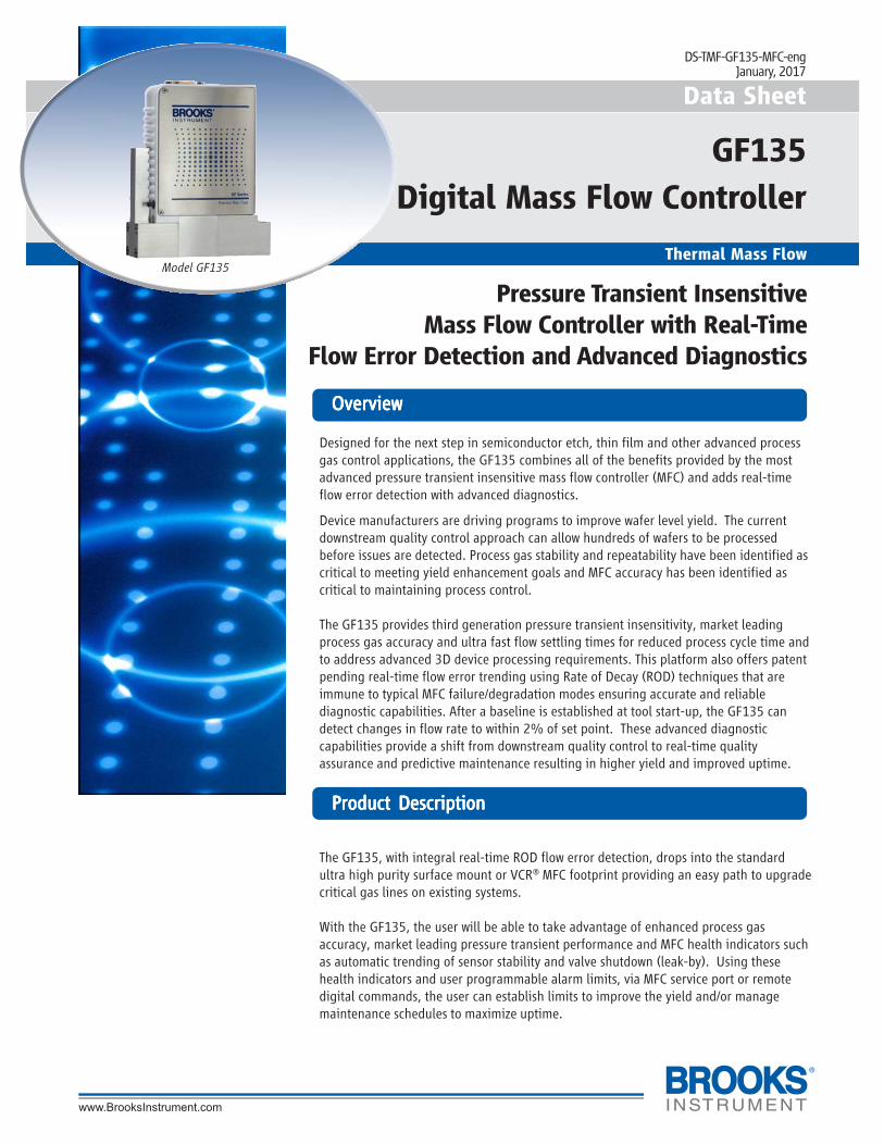
Model GF135
DS-TMF-GF135-MFC-engJanuary, 2017
2
Real-time Flow Error DetectionReal-time Flow Error DetectionReal-time Flow Error DetectionReal-time Flow Error DetectionReal-time Flow Error DetectionProcess contamination buildup in the flow sensor results in higherthan indicated actual flow. Process contamination buildup in theflow restrictor results in lower than indicated actual flow. Processcontamination on the valve orifice or seat results in leak past thevalve. All of these situations can cause lost wafers and costthousands. When using a standard MFC, these errors cannot bedetected without stopping production to run a flow check. TheGF135 has patent pending real-time flow error detection andtrending using Rate of Decay (ROD) techniques that are immune totypical MFC failure/degradation modes ensuring accurate andreliable diagnostic capabilities. After a baseline is established at toolstart-up, the GF135 can detect changes in flow, drift and leak rate.
After installing the GF135, a commissioning routine creates aperformance baseline at actual process conditions. During waferprocessing, the device automatically takes flow error detectionreadings at each new process set point and compares the result tothe baseline. The proprietary ROD measurement techniquemomentarily stops the upstream delivery of gas from the toolsupply while maintaining flow into the process chamber at therequested flow rate. A highly accurate pressure measurement istaken while the gas is being depleted from the inlet volume and anadvanced signal processing algorithm calculates ROD flow rate inreal time. Before the flow to the process is affected by thediminishing pressure, the upstream supply is re-established withno perturbation to the delivered flow. By calculating flow atvarious set points during wafer processing, the MFC detects anysensor or bypass clogging. It also detects if a sensor offset isdeveloping since the effects of clogging and drift manifestthemselves differently at different set points. The same method isused when the MFC is given a zero set point to calculate valve leak.This enables the MFC to measure zero offset. The MFC can reportthe valve leak, sensor offset and flow offset to the tool through adocumented interface protocol, as well as auto-correcting itself ifthe user enables that feature. Finally, the MFC stores this data forone year and can report on the changes using the historical data.
By providing automated monitoring of flow rate changes, theGF135 is able to arm the user with real time warnings of waferimpacting flow deviations.
FeaturFeaturFeaturFeaturFeatures and Benefitses and Benefitses and Benefitses and Benefitses and Benefits
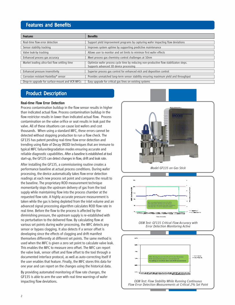
OEM Test: GF135 Critical Flow Accuracy withError Detection Monitoring Active
OEM Test: Flow Stability While Running ContinuousFlow Error Detection Measurements at Critical 2% Set Point
Time (Seconds)
MFC accurately flowing 40 sccm Cl2 (20%)ROD data points collected over 16 minute sError detection data points show tight consistency well within the ± 2% of S.P detection window
MFC flowing 4 sccm Cl2 (2% of F.S.) for 50 minutesROD measurements taken at 5 second intervalsNo spiking or overshoot after each ROD measurement
Real-time flow error detection Support yield improvement programs by capturing wafer impacting flow deviations
Sensor stability tracking Improves system uptime by supporting predictive maintenance
Valve leak-by tracking Allows user to monitor and set limits to minimze first wafer effects
Enhanced process gas accuracy Meet process gas chemistry control challenges at 10nm
Market leading ultra-fast flow settling time Optimize wafer process cycle time by reducing non-productive flow stabilizaton steps.Supports advanced 3D device processing
Enhanced pressure insensitivity Superior process gas control for enhanced etch and deposition control
Corrosion resistant Hastelloy® sensor Provides unmatched long-term sensor stability ensuring maximum yield and throughput
Drop-in upgrade for surface-mount and VCR MFCs Easy upgrade for critical gas lines on existing systems
3
Ultra-Fast ResponseUltra-Fast ResponseUltra-Fast ResponseUltra-Fast ResponseUltra-Fast ResponseBy combining Brooks’ patented flow sensor technology with ahigh speed ARM processor and fast acting diaphragm free valveassembly, the GF Series delivers up to 3 times faster responseand settling time compared to other mass flow controllers,enabling:• Improved wafer throughput by reducing nonproductive flow
settling steps• Critical Etch and 3D device processes requiring ultra-fast sub
500 millisecond etch steps• Reduced diverted gas consumption and associated
abatement costs• Time-sensitive gas delivery steps in Atomic Layer Deposition (ALD)• Processes requiring a slow ramped gas turn-on or time
critical transitions between flow rates with userprogrammable ramp function
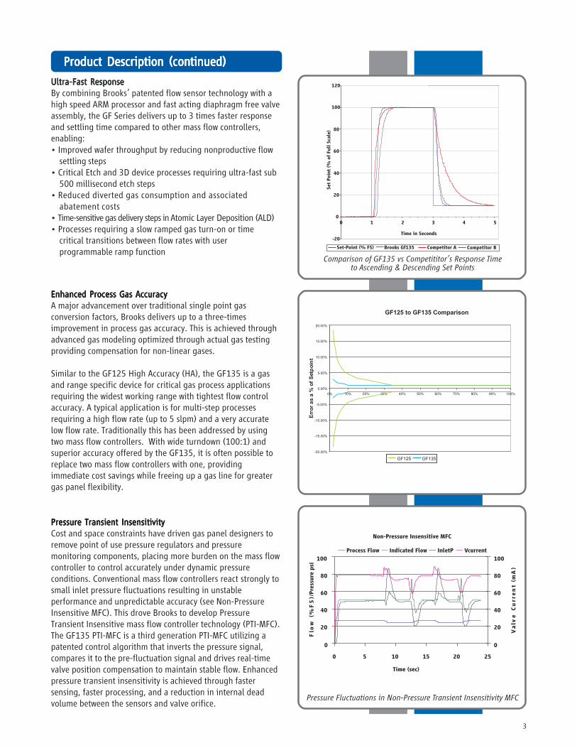
Comparison of GF135 vs Competititor’s Response Timeto Ascending & Descending Set Points
Enhanced Process Gas AccuracyEnhanced Process Gas AccuracyEnhanced Process Gas AccuracyEnhanced Process Gas AccuracyEnhanced Process Gas AccuracyA major advancement over traditional single point gasconversion factors, Brooks delivers up to a three-timesimprovement in process gas accuracy. This is achieved throughadvanced gas modeling optimized through actual gas testingproviding compensation for non-linear gases.
Similar to the GF125 High Accuracy (HA), the GF135 is a gasand range specific device for critical gas process applicationsrequiring the widest working range with tightest flow controlaccuracy. A typical application is for multi-step processesrequiring a high flow rate (up to 5 slpm) and a very accuratelow flow rate. Traditionally this has been addressed by usingtwo mass flow controllers. With wide turndown (100:1) andsuperior accuracy offered by the GF135, it is often possible toreplace two mass flow controllers with one, providingimmediate cost savings while freeing up a gas line for greatergas panel flexibility.
Pressure Fluctuations in Non-Pressure Transient Insensitivity MFC
Pressure Transient InsensitivityPressure Transient InsensitivityPressure Transient InsensitivityPressure Transient InsensitivityPressure Transient InsensitivityCost and space constraints have driven gas panel designers toremove point of use pressure regulators and pressuremonitoring components, placing more burden on the mass flowcontroller to control accurately under dynamic pressureconditions. Conventional mass flow controllers react strongly tosmall inlet pressure fluctuations resulting in unstableperformance and unpredictable accuracy (see Non-PressureInsensitive MFC). This drove Brooks to develop PressureTransient Insensitive mass flow controller technology (PTI-MFC).The GF135 PTI-MFC is a third generation PTI-MFC utilizing apatented control algorithm that inverts the pressure signal,compares it to the pre-fluctuation signal and drives real-timevalve position compensation to maintain stable flow. Enhancedpressure transient insensitivity is achieved through fastersensing, faster processing, and a reduction in internal deadvolume between the sensors and valve orifice.
at low setpoints• Improved reproducibility at elevated temperatures through
new isothermal packaging, onboard conditioning electronicswith ambient temperature sensing and compensation
• Improved long-term stability through enhanced sensormanufacturing and burn in process
• Highly corrosion resistant Hastelloy C-22 sensor tube• Optimized temperature profile for gases prone to thermal
decomposition
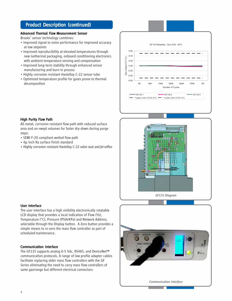
Communication Interface
GF135 Diagram
High Purity Flow PathHigh Purity Flow PathHigh Purity Flow PathHigh Purity Flow PathHigh Purity Flow PathAll metal, corrosion resistant flow path with reduced surfacearea and un-swept volumes for faster dry-down during purgesteps:• SEMI F-20 compliant wetted flow path• 4μ inch Ra surface finish standard• Highly corrosion resistant Hastelloy C-22 valve seat and jet orifice
User InterfaceUser InterfaceUser InterfaceUser InterfaceUser InterfaceThe user interface has a high visibility electronically rotatableLCD display that provides a local indication of Flow (%),Temperature (°C), Pressure (PSIA/KPa) and Network Address,selectable through the Display button. A Zero button provides asimple means to re-zero the mass flow controller as part ofscheduled maintenance.
Communication InterfaceCommunication InterfaceCommunication InterfaceCommunication InterfaceCommunication InterfaceThe GF135 supports analog 0-5 Vdc, RS485, and DeviceNet™communication protocols. A range of low profile adapter cablesfacilitate replacing older mass flow controllers with the GFSeries eliminating the need to carry mass flow controllers ofsame gas/range but different electrical connectors.
Etch ProcessEtch ProcessEtch ProcessEtch ProcessEtch ProcessThe transition to 22nm and 10nm nodes and complex 3Ddevice geometries place greater profile and variability controlchallenges on the etch tool and its gas delivery sub system.
Creating and maintaining highly reproducible gas chemistryrequires leading edge mass flow control.
The GF135 is the preferred mass flow controller fordemanding etch applications. With ultra fast 300msec flowsettling time, market leading pressure transient insensitivity,wide rangeability, process gas accuracy and real-time flowerror detection with advanced diagnostics, the GF135 is theright choice for these demanding applications.
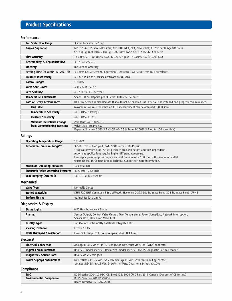
ZZZZZererererero Stability:o Stability:o Stability:o Stability:o Stability: < +/- 0.5% F.S. per year
TTTTTemperemperemperemperemperaturaturaturaturature Coefficiene Coefficiene Coefficiene Coefficiene Coefficient:t:t:t:t: Span: 0.05% setpoint per °C, Zero: 0.005% F.S. per °C
Rate-of-Decay PRate-of-Decay PRate-of-Decay PRate-of-Decay PRate-of-Decay Performance:erformance:erformance:erformance:erformance: (ROD by default is disabled/off. It should not be enabled until after MFC is installed and properly commissioned)
Flow Rate:Flow Rate:Flow Rate:Flow Rate:Flow Rate: Maximum flow rate for which an ROD measurement can be obtained is 800 sccm
TTTTTemperemperemperemperemperaturaturaturaturature Sensitivity:e Sensitivity:e Sensitivity:e Sensitivity:e Sensitivity: +/- 0.04% S.P./Deg C
DifferDifferDifferDifferDifferenenenenential Prtial Prtial Prtial Prtial Pressuressuressuressuressure Range**:e Range**:e Range**:e Range**:e Range**: 3-860 sccm = 7-45 psid, 861- 5000 sccm = 10-45 psid**Typical pressure drop. Actual pressure drop will be gas and flow dependent.Argon gas applications require higher differential pressure.Low vapor pressure gases require an inlet pressure of > 100 Torr, with vacuum on outlet(example SiCl4). Contact Brooks Technical Support for more information.
Maximum OperMaximum OperMaximum OperMaximum OperMaximum Operating Prating Prating Prating Prating Pressuressuressuressuressure:e:e:e:e: 100 psia max
Electrical Connection:Electrical Connection:Electrical Connection:Electrical Connection:Electrical Connection: Analog/RS-485 via 9-Pin “D” connector, DeviceNet via 5-Pin “M12” connector
Digital Communication:Digital Communication:Digital Communication:Digital Communication:Digital Communication: RS485+ (model specific), DeviceNet (model specific), RS485 Diagnostic Port (all models)
Diagnostic / Service PDiagnostic / Service PDiagnostic / Service PDiagnostic / Service PDiagnostic / Service Port:ort:ort:ort:ort: RS485 via 2.5 mm jack
Brooks is committed to assuring all of our customers receive the ideal flow solution for their application, along with outstandingservice and support to back it up. We operate first class repair facilities located around the world to provide rapid response andsupport. Each location utilizes primary standard calibration equipment to ensure accuracy and reliability for repairs and recalibra-tion and is certified by our local Weights and Measures Authorities and traceable to the relevant International Standards.
Visit www.BrooksInstrument.com to locate the service location nearest to you.
STSTSTSTSTARARARARARTTTTT-UP SERVICE -UP SERVICE -UP SERVICE -UP SERVICE -UP SERVICE AND IN-SITU CALIBRAAND IN-SITU CALIBRAAND IN-SITU CALIBRAAND IN-SITU CALIBRAAND IN-SITU CALIBRATIONTIONTIONTIONTION
Brooks Instrument can provide start-up service prior to operation when required. For some process applications, where ISO-9001Quality Certification is important, it is mandatory to verify and/or (re)calibrate the products periodically. In many cases this servicecan be provided under in-situ conditions, and the results will be traceable to the relevant international quality standards.
CUSTCUSTCUSTCUSTCUSTOMER SEMINARS OMER SEMINARS OMER SEMINARS OMER SEMINARS OMER SEMINARS AND AND AND AND AND TRAININGTRAININGTRAININGTRAININGTRAINING
Brooks Instrument can provide customer seminars and dedicated training to engineers, end users, and maintenance persons.
Please contact your nearest sales representative for more details.Due to Brooks Instrument's commitment to continuous improvement of our products, all specifications are subject to change without notice.
BrBrBrBrBrooks Service and Supportooks Service and Supportooks Service and Supportooks Service and Supportooks Service and Support
TRADEMARKSBrooks, MultiFlo ............................................................. Brooks Instrument, LLCAll other trademarks are the property of their respective owners.