Piston pump unit Product series KFG For fluid grease and grease For use in SKF MonoFlex and SKF ProFlex centralized lubrication systems Features: Delivery rates: 0.8 to 15 cm³ / min • Fluids delivered: Fluid grease and grease • Reservoir capacities: 2 to 20 kg • Patented grease follower plate system • for position-independent application (e.g. rotary application in wind energy systems) Integrated fill level monitoring • Control unit that can be integrated • For us in vehicles, Industrial and wind • energy systems Piston pump units for vehicle applications • with E1 (KBA) certification Advantages: Reliable: due to sturdy materials, very • durable components and designs for extreme conditions (with positively driven pump elements) Application-oriented: individual designs • through user-friendly product customizer Versatile: can be used as a single line • (SKF MonoFlex) and as a progressive pump (SKF ProFlex) Safe: through fill level monitoring, • lubrication system monitoring, pressure relief and control unit
Transcript
Piston pump unit
Product series KFGFor fluid grease and greaseFor use in SKF MonoFlex and SKF ProFlex centralized lubrication systems
Features:
Delivery rates: 0.8 to 15 cm³ / min•
Fluids delivered: Fluid grease and grease•
Reservoir capacities: 2 to 20 kg•
Patented grease follower plate system •
for position-independent application
(e.g. rotary application in wind energy
systems)
Integrated fill level monitoring•
Control unit that can be integrated•
For us in vehicles, Industrial and wind •
energy systems
Piston pump units for vehicle applications •
with E1 (KBA) certification
Advantages:
Reliable: due to sturdy materials, very •
durable components and designs for
extreme conditions (with positively
driven pump elements)
Application-oriented: individual designs •
through user-friendly product customizer
Versatile: can be used as a single line •
(SKF MonoFlex) and as a progressive
pump (SKF ProFlex)
Safe: through fill level monitoring, •
lubrication system monitoring,
pressure relief and control unit
PU
B L
S/P
2 1
2649 E
N · 1
-3030-EN
! Important information on product usageAll products from SKF may be used only for their intended purpose as described in this
brochure and in any instructions. If operating instructions are supplied with the products, they must be read and followed.
Not all lubricants are suitable for use in centralized lubrication systems. SKF does offer an inspection service to test customer supplied lubricant to determine if it can be used in a central-ized system. SKF lubrication systems or their components are not approved for use with gases, liquefied gases, pressurized gases in solution and fluids with a vapor pressure exceeding normal atmospheric pressure (1 013 mbar) by more than 0,5 bar at their maximum permissible temperature.
Hazardous materials of any kind, especially the materials classified as hazardous by European Community Directive EC 67/548/EEC, Article 2, Par. 2, may only be used to fill SKF centralized lubrication systems and components and delivered and/or distributed with the same after consulting with and receiving written approval from SKF.
2
PU
B L
S/P
2 1
2649 E
N · 1
-3030-EN
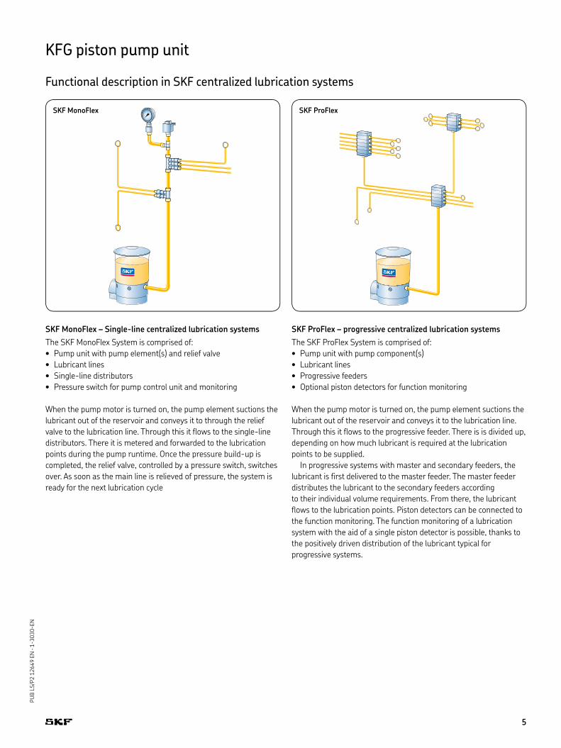
KFG piston pump unit
Table of contents
OverviewSKF system family Field of application Page
SKF MonoFlex SKF ProFlex Rotary Industry Vehicle
Control unit Without internal and external control unit – • • • • 8Internal control unit IG502-2-I – • • • • 8Internal control unit LC502 • • • • • 8
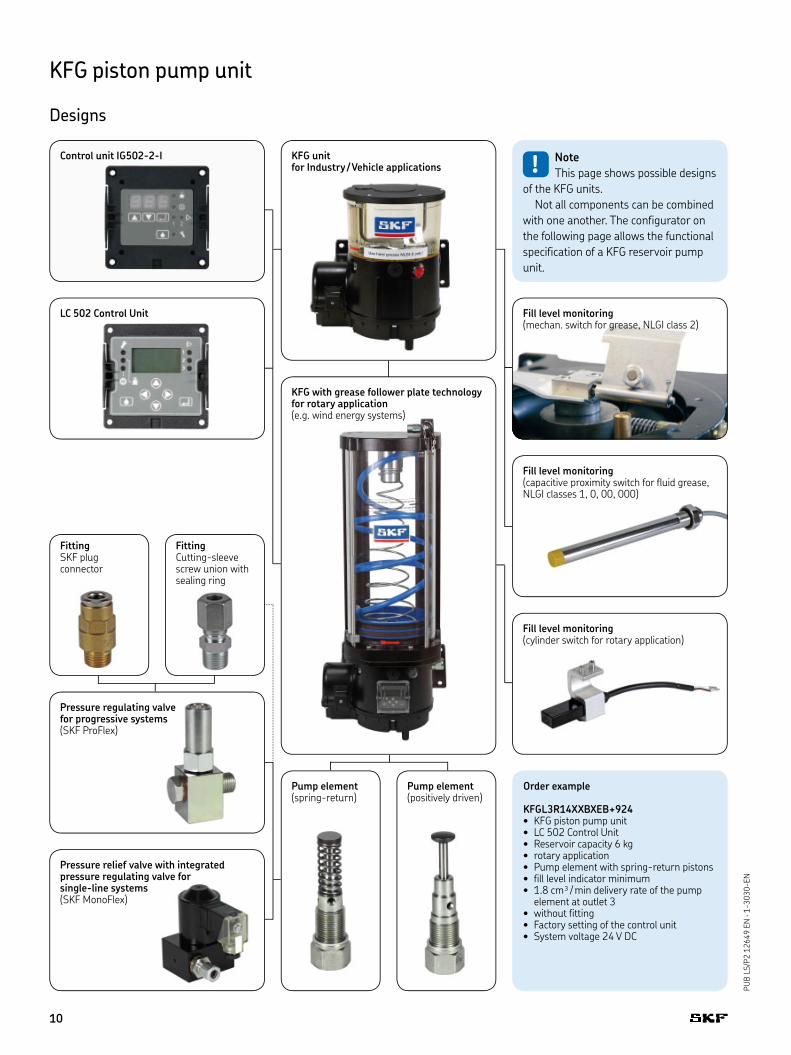
KFGL3R14XXBXEB+924KFG piston pump unit• LC 502 Control Unit• Reservoir capacity 6 kg• rotary application• Pump element with spring-return pistons• fill level indicator minimum• 1.8 cm³ / min delivery rate of the pump • element at outlet 3without fitting• Factory setting of the control unit• System voltage 24 V DC•
KFG with grease follower plate technology for rotary application (e.g. wind energy systems)
KFG unit for Industry / Vehicle applications
FittingCutting-sleeve screw union with sealing ring
! Note
This page shows possible designs
of the KFG units.
Not all components can be combined
with one another. The configurator on
the following page allows the functional
specification of a KFG reservoir pump
unit.
Pump element(spring-return)
Pump element(positively driven)
Control unit IG502-2-I
LC 502 Control Unit
Fill level monitoring (capacitive proximity switch for fluid grease, NLGI classes 1, 0, 00, 000)
Pressure relief valve with integrated pressure regulating valve for single-line systems(SKF MonoFlex)
Fill level monitoring(cylinder switch for rotary application)
Fill level monitoring(mechan. switch for grease, NLGI class 2)
10
PU
B L
S/P
2 1
2649 E
N · 1
-3030-EN
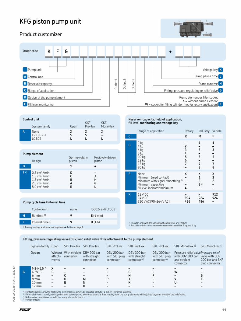
KFG piston pump unit
Product customizer
Order code K F G +
O
utlet 1
Pump unit
O
utlet 2
O
utlet 3
Voltage key K
A Control unit Pump pause time J
B Reservoir capacity Pump runtime H
C Range of application Fitting, pressure regulating or relief valve G
D Design of the pump element Pump element or filler socket X = without pump element
W = socket for filling cylinder (not for rotary application)E Fill level monitoring F
Fitting, pressure regulating valve (DBV) and relief valve 4) for attachment to the pump element
System family Open SKF ProFlex SKF ProFlex SKF ProFlex SKF ProFlex SKF ProFlex SKF MonoFlex 5) SKF MonoFlex 5)
Design Without attach-ments
With straight connector
DBV 200 bar with straight connector
DBV 200 barwith SKF plugconnector
DBV 300 barwith straight connector 6)
DBV 300 barwith SKF plugconnector 6)
Pressure relief valvewith DBV 200 bar and straight connector
Pressure relief valve with DBV 200 bar and SKF plug connector
M14×1.5 7) X – – – – – – –G G 1/4 " 7) B – – – G – W –
6 mm – C – – H F – S8 mm – D M P J L V T10 mm – E N – K – U –12 mm – – O – – – – –
4) For technical reasons, the first pump element must always be installed at Outlet 1 in SKF MonoFlex systems. 5) If the relief valve is configured together with several pump elements, then the lines leading from the pump elements will be joined together ahead of the relief valve.6) Not possible in combination with the pump elements E and L7) Female thread
Pump element
DesignSpring-return piston
Positively driven piston
D 1 4
F 4) 0.8 cm³ / min D –1.3 cm³ / min C J1.8 cm³ / min B H2.5 cm³ / min A G5.0 cm³ / min E L
Reservoir capacity, field of application, fill level monitoring and voltage key
Range of application Rotary Industry Vehicle
C R M F
B2 kg – 1 14 kg 2 – –6 kg 3 3 38 kg 4 – –10 kg 5 5 512 kg 6 – –15 kg 7 7 720 kg – 8 8
E None X X XMinimum (reed contact) – 1 1Minimum with signal smoothing 2) – 2 2Minimum capacitive – 3 3) –fill level indicator minimum 4 – –
K 12 V DC – – 91224 V DC 924 924 924230 V AC (90–264 V AC ) 486 486 –
2) Possible only with the variant without control unit (KFGX)3) Possible only in combination the reservoir capacities 2 kg and 6 kg
Control unit
System family OpenSKF ProFlex
SKF MonoFlex
A None X X XIG502-2-I S S –LC 502 L L L
Pump cycle time / Interval time
Control unit none IG502-2-I / LC502
H Runtime 1) 9 E (4 min)
J Interval time 1) 9 B (1 h)
1) Factory setting, additional setting times ➔ Tables on page 8
11
PU
B L
S/P
2 1
2649 E
N · 1
-3030-EN
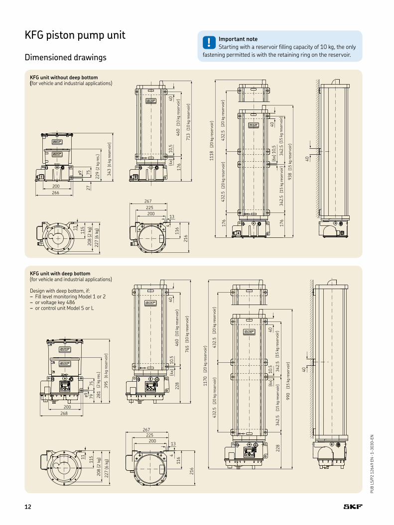
KFG piston pump unit
Dimensioned drawings
KFG unit without deep bottom (for vehicle and industrial applications)
KFG unit with deep bottom (for vehicle and industrial applications)
Design with deep bottom, if:Fill level monitoring Model 1 or 2–or voltage key 486–or control unit Model S or L–
(2 k
g r
es.
)
(6 k
g r
ese
rvoir
)
(10 k
g r
ese
rvoir
)
(10 k
g r
ese
rvoir
)
(20 k
g r
ese
rvoir
)
(20 k
g r
ese
rvoir
)(2
0 k
g r
ese
rvoir
)
(15 k
g r
ese
rvoir
)(1
5 k
g r
ese
rvoir
)
(15 k
g r
ese
rvoir
)
(2 k
g r
es.
)
(6 k
g r
ese
rvoir
)
(10 k
g r
ese
rvoir
)
(10 k
g r
ese
rvoir
)
(20 k
g r
ese
rvoir
)
(20 k
g r
ese
rvoir
)(2
0 k
g r
ese
rvoir
)
(15 k
g r
ese
rvoir
)(1
5 k
g r
ese
rvoir
)
(15 k
g r
ese
rvoir
)
! Important note
Starting with a reservoir filling capacity of 10 kg, the only
fastening permitted is with the retaining ring on the reservoir.
12
PU
B L
S/P
2 1
2649 E
N · 1
-3030-EN
KFG piston pump unit
Dimensioned drawings
KFG unit without deep bottom (for rotary application)
KFG unit with deep bottom (for rotary application)
Design with deep bottom, if:voltage key 486–or control unit Model S or L–
(6 k
g r
ese
rvoir
)
(4 k
g r
ese
rvoir
) (10 k
g r
ese
rvoir
)
(10 k
g r
ese
rvoir
)
(8 k
g r
ese
rvoir
)
(8 k
g r
ese
rvoir
)
(15 k
g r
ese
rvoir
)
(15 k
g r
ese
rvoir
)(1
5 k
g r
ese
rvoir
)
(12 k
g r
ese
rvoir
)(1
2 k
g r
ese
rvoir
)
(12 k
g r
ese
rvoir
)
(6 k
g r
ese
rvoir
)
(4 k
g r
ese
rvoir
)
(10 k
g r
ese
rvoir
)
(10 k
g r
ese
rvoir
)
(8 k
g r
ese
rvoir
)
(8 k
g r
ese
rvoir
)
(15 k
g r
ese
rvoir
)
(15 k
g r
ese
rvoir
)(1
5 k
g r
ese
rvoir
)
(12 k
g r
ese
rvoir
)(1
2 k
g r
ese
rvoir
)
(12 k
g r
ese
rvoir
)
! Important note
Starting with a reservoir filling capacity of 10 kg, the only
fastening permitted is with the retaining ring on the reservoir.
4 kg 11 kg 2 kg 6 kg6 kg 12 kg 6 kg 7 kg8 kg 14 kg 10 kg 14 kg10 kg 15 kg 15 kg 16 kg12 kg 17 kg 20 kg 18 kg15 kg 18 kg
General conditions for electrical connections
Ratedvoltage
Power con-sump-tion 1)
Power con-sumption (max)
Pump startingcurrent (approx. 20 ms)
Maximum back-up fuse for industrial and rotary application
Maximum back-up fuse for ve-hicle appli-cation 2)
12 V DC 2.4 A < 5 A 9 A – 5 AT24 V DC 1.25 A < 2.5 A 4.5 A 4 AT 3 AT 115 V AC K.A. 1.5 A 20 A C6A 3) –230 V AC K.A. 0.9 A 40 A C6A 3) –
1) Typical values for an ambient temperature of approx. 25 °C and an operating pressure of 150 bar (load-dependent)2) Fuse protection in accordance with DIN72581 T33) Fuse protection of the characteristic C
General information
Operating temperature:spring-return pump elements (for 115 / 230 V AC only to +60 °C). . . . . . . -25 to +70 °C
Positively driven pump elements (for 115 / 230 V AC only to +60 °C). . . . . . . -30 to +70 °C
Lubricant. . . . . . . . . . . . . . . . . . . . . . . . . . NLGI Grades 000 to 2 with EP additives, compatible with plastics, NBR elastomers, copper and copper alloys
Flow pressure . . . . . . . . . . . . . . . . . . . . . . up to max. 700 mbar(Pump elements from 0.8–2.5 cm3 / min)
Flow pressure . . . . . . . . . . . . . . . . . . . . . . up to max. 450 mbar(Pump elements with 5.0 cm3 / min)
Protection class according to DIN 40050, T9 IP56
Pump housing and reservoir
Pump housing material . . . . Aluminum-silicon cast alloy
Positively driven pump element . . . . . . .1.3; 1.8; 2.5; 5.0 cm³ / min
Maximum back pressure:Spring-return pump element . . . . . . . . .300 bar (200 bar for pump
element with 5.0 cm³/min)
Positively driven pump element . . . . . . .350 bar (250 bar for pump element with 5.0 cm³/min)
Fill level switch
Capacitive proximity switches
Mechan-ical fill level switch
Mechan. fill level switch with signal smoothing
Cylinderswitch
Max. switched voltage
10–30 V DC 24 V DC 30 V DC 1–48 V AC/DC
Max. switched current
200 mA 25 mA n.s. 0.5 A
Max. swit-ching capacity
n.s. 0.6 W 60 W 5 W
Type of contact NO-contact NO-contact Changeover Changeover
Connection:for KFG with-out control unit
4-pin circular plug M12x1
4-pin circular plug M12x1 (Industry)
4-pin circular socket M12x1 (Industry)
Square connector 4)
7-pin circular plug (Vehicle)
7-pin circular plug (Vehicle)
for KFG with control unit
Internal connection
Internal connection
– Internal connection 5)
Internal power consumption
6–12 mA – – –
Voltage drop ≤ 1.8 V – – –
4) Cable socket according to DIN EN 175301-803 5) Only for use with the IG502-2-I or the LC502 230 V;
when using the LC502 24 V, the connection is a 4-pin circular connector M12x1
14
PU
B L
S/P
2 1
2649 E
N · 1
-3030-EN
KFG piston pump unit
Accessories
Filler coupling
As an alternative to a conical head nipple,
the unit can also be equipped with a filler
socket in order to fill it with a filling pump,
e.g. the manual drum pump. A correspond-
ing coupling socket and a hose socket must
be mounted on the filling pump.
Filling coupling Part A
Description Order number
Filler socket 24-9909-0244with sealing ring
Manual drum pump
The manual drum pump is for simple filling-
up of the KFG piston pump unit. It is avail-
able in the designs with and without trolley
and is suitable for NLGI class 1 and 2 greas-
es. The delivery rate of the drum pump is
approx. 40 cm³/stroke.
Filling cylinder
Description Order number
Filling cylinder 169-000-171
Drum pump
Description Order number
Drum pump withrunning gear:For 25 kg drum 169-000-042For 50 kg drum 169-000-054
Drum pump withoutrunning gear:For 25 kg drum 169-000-342
Filling cylinder
For industry and vehicle applications, a fill-
ing cylinder can also be optionally used to fill
the pump unit through one of the lubricant
outlets. To accomplish this, a filler socket
must be configured in the order code in
place of a lubricant outlet.
Coupling socket
Hose socket
Filler socket
Filler coupling Part C
Description Order number
Hose socket:ø13 mm 857-760-007ø16 mm 857-870-002
Filler coupling Part B
Description Order number
Coupling socket 995-001-500
15
PU
B L
S/P
2 1
2649 E
N · 1
-3030-EN
Pressure gauge
Reed pen pressure gauges with glycerin
filling are available for visual documentation
of the pressures in the SKF centralized
lubrication system. The parts which come
into contact with the medium are made of
copper alloys. These pressure gauges are
suitable for highly dynamic pressure loads
and vibrations. The necessary accessory
parts for fastening are to be found in the
leaflet 1-0103-EN.
Pressure gauge
Description Order number
Pressure gauge, complete:0 to 250 bar 169-125-000.U10 to 400 bar 169-140-001.U1
Pressure gauge screw union: for ø 6 mm tubing 441-106-162for ø 8 mm tubing 441-108-162for ø 10 mm tubing 441-110-163for ø 12 mm tubing 441-112-162
IG502-2-E external control unit
The IG502-2-E is an external control unit
with a control display. It controls the turning
on and off of the KFG pump by means of in-
terval and pump runtimes. Furthermore, it
enables the fill level monitoring of the lubri-
cant reservoir and the evaluation on one
piston detector signal. In addition, one can
operate the pump unit with it, even from a
short distance, e.g. from the cab of a vehicle.
It is suitable only for SKF ProFlex systems.
KFG piston pump unit
Accessories
Retaining ring and drilling template
For all KFG units with reservoir capacities
up to and including 6 kg, a special drilling
template exists as an installation aid made
of self-adhesive foil. In addition to that, a
stabilizing retaining angle is also available
for vertical installation.
Electrical accessories
The T plug is suitable when additional
connectors are required, e.g. for a separate
indicator lamp.
External control unit
Description Order number
External control unit
IG502-2-E(Always please include specification of the control voltage 12 V or 24 V)
Retaining ring and drilling template
Description Order number
Self-adhesive drilling template 951-130-115
Pump retaining plate 881-290-430
Electrical accessories
Description Order number
T-plug M12×1 with two outgoing cables (socket M12×1)
179-990-700
16
PU
B L
S/P
2 1
2649 E
N · 1
-3030-EN
KFG piston pump unit
Special designs
KFG with CAN bus control unit (KFGC)
The KFGC (CAN bus) variant is based on
the KFG series and has an integrated CAN
bus control unit (LC-CAN5000). The control
unit with the CAN bus interface SAE J1939
permits the integration of the lubrication
system in the CAN bus and thus enables
the input and evaluation of a large number
of parameters for the control unit and moni-
toring of the system. It can however also be
used as a stand-alone solution and be con-
nected to a PC via a CAN bus plug/CAN bus
adapter or through an infrared interface.
Interesting for:all those who use CAN bus and who •
would like to enter, display and evaluate
the lubrication system data at a central
location
all those who require individual settings •
and monitoring of up to four independent
valves and/or lubrication circuits
(complex systems)
all those who wish to call up the error log •
through the PC
Result:Implementation of tailored lubrication con-
cepts for each lubrication circuit in the lubri-
cation system (independent and according
to need).
KFG sea water-resistant
Basically, all KFG variants are available in
sea water-resistant versions. Individual
components for protection against corrosion
(corrosion class C5-M) are coated for this
purpose and combined with stainless steel
components.
KFGC
KFGC (view from below)
KFG(sea water-resistant design)
! Note
For inquiries regarding possible variants and designs, please contact
an SKF Lubrication Systems representative.
! Note
For inquiries regarding possible variants and designs, please contact
an SKF Lubrication Systems representative.
17
PU
B L
S/P
2 1
2649 E
N · 1
-3030-EN
12–14 45
53
1–9
15–24
50
1–9
49
47
42
48! Only original spare parts from
SKF Lubrication Systems
Germany AG may be used.
Unauthorized alterations to products
and the use of non-original spare parts
and accessories are not permitted.
! Dismantling of the product or
individual parts thereof within the
statutory warranty period is not permit-
ted and voids any claims.
! Repair work may only be per-
formed by the Service depart-
ment of SKF Lubrication Systems Ger-
many AG. In the event of questions in
reference to installation or maintenance,
please contact SKF Lubrication Systems
Germany AG or a an SKF-authorized
dealer or service partner.
KFG piston pump unit
Exploded-view and spare parts drawings
51
44
52
41
4340 4644
SKF MonoFlex design A with three pump elements
SKF MonoFlex design B with two pump elements
SKF MonoFlex design C with two pump elements
25–39 25–3925–3961 61
61
59
5611
54
56
57
58
55
54
60
55
54
11
5511
5411
18
PU
B L
S/P
2 1
2649 E
N · 1
-3030-EN
KFG piston pump unit
Wearing parts and spare parts
1) DBV=pressure regulating valve
Wearing parts
Item Order number Letter Description
1 KFG1.U0 E Pump element with spring-return piston 5.0 cm³/min2 KFG1.U1 A Pump element with spring-return piston 2.5 cm³/min3 KFG1.U2 B Pump element with spring-return piston 1.8 cm³/min4 KFG1.U3 C Pump element with spring-return piston 1.3 cm³/min5 KFG1.U4 D Pump element with spring-return piston 0.8 cm³/min6 KFG1.U0-E L Pump element with positively driven piston 5.0 cm³/min7 KFG1.U1-E G Pump element with positively driven piston 2.5 cm³/min8 KFG1.U2-E H Pump element with positively driven piston 1.8 cm³/min9 KFG1.U3-E J Pump element with positively driven piston 1.3 cm³/min
Spare parts
Item Order number Letter Description
10 301-034 B Adapter M14x1.5 on G1/4 (sealing ring Item 11 must be ordered separately)11 DIN7603-A14X18-AL – Sealing ring12 406-413 C Straight connector for tube ø 6 mm13 408-413 D Straight connector for tube ø 8 mm14 410-403 E Straight connector for tube ø 10 mm15 161-210-063 M DBV 1) 200 bar, straight connector ø 8 mm16 161-210-065 N DBV 1) 200 bar, straight connector ø 10 mm17 161-210-062 O DBV 1) 200 bar, straight connector ø 12 mm18 161-210-061 P DBV 1) 200 bar, SKF plug connector ø 8 mm19 161-210-036 G DBV 1) 300 bar, female thread G1/420 161-210-012 H DBV 1) 300 bar, straight connector ø 6 mm21 161-210-024 J DBV 1) 300 bar, straight connector ø 8 mm22 161-210-066 K DBV 1) 300 bar, straight connector ø 10 mm23 161-210-021 F DBV 1) 300 bar, SKF plug connector ø 6 mm24 161-210-034 L DBV 1) 300 bar, SKF plug connector ø 8 mm25 24-1254-2634 W Relief valve with DBV 1) 200 bar, female thread G1/4, 12 V design26 24-1254-2635 W Relief valve with DBV 1) 200 bar, female thread G1/4, 24 V design27 24-1254-2636 W Relief valve with DBV 1) 200 bar, female thread G1/4, 230 V design28 24-1254-2640 V Relief valve with DBV 1) 200 bar, straight connector ø 8 mm, 12 V design29 24-1254-2641 V Relief valve with DBV 1) 200 bar, straight connector ø 8 mm, 24 V design30 24-1254-2642 V Relief valve with DBV 1) 200 bar, straight connector ø 8 mm, 230 V design31 24-1254-2637 U Relief valve with DBV 1) 200 bar, straight connector ø 10 mm, 12 V design32 24-1254-2638 U Relief valve with DBV 1) 200 bar, straight connector ø 10 mm, 24 V design33 24-1254-2639 U Relief valve with DBV 1) 200 bar, straight connector ø 10 mm, 230 V design34 24-1254-2643 S Relief valve with DBV 1) 200 bar, SKF plug connector ø 6 mm, 12 V design35 24-1254-2644 S Relief valve with DBV 1) 200 bar, SKF plug connector ø 6 mm, 24 V design36 24-1254-2645 S Relief valve with DBV 1) 200 bar, SKF plug connector ø 6 mm, 230 V design37 24-1254-2646 T Relief valve with DBV 1) 200 bar, SKF plug connector ø 8 mm, 12 V design38 24-1254-2647 T Relief valve with DBV 1) 200 bar, SKF plug connector ø 8 mm, 24 V design39 24-1254-2648 T Relief valve with DBV 1) 200 bar, SKF plug connector ø 8 mm, 230 V design40 KFGS1.54 – Transparent cover for the control unit41 24-9909-0241 – KFG filling nipple G1/4 kit42 24-9909-0248 – KFG DBV 1) in the housing 1.5 bar G1/4 kit (rotary application)43 24-9909-0242 – KFG screw plug G1/4 kit44 24-9909-0247 – KFG DBV in the housing 1.5 bar M20x1.5 kit (rotary application)45 169-000-174 – KFG filler socket M20x1.5 kit (Industry, Vehicle)46 KFG1.128 – Screw plug, plastic, with O-ring M20x1.5 (Industry, Vehicle)47 24-9909-0250 – KFG screw plug, steel M20x1.5 kit (rotary application)48 24-9909-0244 – KFG filler coupling G1/4 kit49 24-9909-0249 – KFG DBV 1) on the housing cover 30 bar G1/4 kit (rotary application)50 24-9909-0243 – KFG fastening kit (for reservoir capacities from 8 kg to 20 kg only)51 24-9909-0246 – KFG sensor / actuator box kit, 230 V (+486) Industry or rotary application52 24-9909-0251 – KFG fill level monitoring with square connector kit (rotary application)53 24-9909-0252 – KFG fill level monitoring with M12x1 plug (rotary application)54 408-313 – Threaded socket55 443-308-351 – Elbow connector56 44-1741-2953 – Pre-bent tubing57 44-1741-2954 – Pre-bent tubing58 445-808-351 – Union T59 44-1741-2956 – Pre-bent tubing60 44-1741-2955 – Pre-bent tubing61 24-9909-0245 – SKF MonoFlex return line G1/4 kit
19
Bearings and unitsSeals Lubrication
systems
Mechatronics Services
The Power of Knowledge Engineering
Drawing on five areas of competence and application-specific expertise amassed over more than 100
years, SKF brings innovative solutions to OEMs and production facilities in every major industry world-
wide. These five competence areas include bearings and units, seals, lubrication systems, mechatronics
(combining mechanics and electronics into intelligent systems), and a wide range of services, from 3-D
computer modelling to advanced condition monitoring and reliability and asset management systems.
A global presence provides SKF customers uniform quality standards and worldwide product availability.
This leaflet was presented to you by:
® SKF, SKF MonoFlex, SKF ProFlex and SKF WindLub are registered trademarks of the SKF Group.