201
Components and solutions for photovoltaic systems Catalogue 2011
| Date post: | 11-Nov-2014 |
| Category: |
Documents |
| Upload: | n1ghtspl1nt3r |
| View: | 167 times |
| Download: | 16 times |

Co
mp
on
ents
an
d s
olu
tio
ns
for
ph
oto
volt
aic
syst
ems
Cat
alo
gu
e 2
011
Components and solutions for photovoltaic systemsCatalogue 2011
Order number:1296070000/09/2011/SMDM
Components and solutions for photovoltaic systems
Photovoltaic energy is a vital element of energy production from renewable energy sources. Its share of the electricity production will continue to increase significantly.
With our continuously expanding, comprehensive product range for the safe and reliable operation of photovoltaic systems, Weidmüller is a recognised market partner. Our consistent focus on innovative technologies for power generation produces dividends for our customers. With a broad range of highly effective components and solutions specially designed to meet the requirements of the photovoltaic market, Weidmüller increases the efficiency of photovoltaic systems.
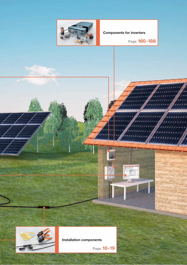
An example of this is the junction box for photovoltaic panels. It permits fully automatic processing which accelerates the production of photovoltaic panels thereby optimising manufacturing costs. A wide range of pre-wired combiner boxes has been designed specifically for the requirements of 1,000 V DC systems, and they contain surge protection that is exactly right for the job. The option of integrated performance monitoring ensures that the photovoltaic system is operating at its maximum potential. Find out more about other products like CLINICS SOLAR, a unique tool for diagnosing photovoltaic panels, surge protection, photovoltaic plug-in connectors and professional tools for working with PV systems.
• Panel connection
• Installation components
• Monitoring systems
• Combiner boxes and components
• Components for inverters
www.weidmueller.com
ArgentinaAustraliaAustriaAzerbaijan BahrainBelarusBelgiumBosnia andHerzegovinaBrazilBulgariaCanadaChileChinaColombiaCosta RicaCroatiaCzech RepublicDenmarkEcuadorEgyptEstoniaFinlandFranceGermanyGreat BritainGreeceHong KongHungaryIcelandIndia
IndonesiaIranIrelandIsraelItalyJapanJordanKazakhstanKoreaKuwaitLatviaLebanonLithuaniaLuxembourgMacedoniaMalaysiaMaltaMexicoMoldovaNetherlandsNew ZealandNorwayOmanPakistan PeruPhilippinesPolandPortugalQatarRomaniaRussia
Saudi ArabiaSerbiaSingaporeSlovakiaSloveniaSouth AfricaSpainSwedenSwitzerlandTaiwanThailandTunisiaTurkeyUkraineUnited ArabEmiratesUnited StatesUruguayUzbekistanVenezuelaVietnam
Weidmüller is a leading international provider of solutionsfor electrical connectivity, transmission and conditioningof power, signal and data in industrial environments.
The company with headquarters in Detmold/Germanydevelops, produces and sells products in the field ofelectrical connectivity and electronics all over the world.Via a network of application specialists Weidmüller offersengineering services and develops application specificsolutions.
The complete product and service portfolio consistentlyassures both Weidmüller and its customers ofcompetitive advantages and an increase in value.

Co
mp
on
ents
an
d s
olu
tio
ns
for
ph
oto
volt
aic
syst
ems
Cat
alo
gu
e 2
011
Components and solutions for photovoltaic systemsCatalogue 2011
Order number:1296070000/09/2011/SMDM
Components and solutions for photovoltaic systems
Photovoltaic energy is a vital element of energy production from renewable energy sources. Its share of the electricity production will continue to increase significantly.
With our continuously expanding, comprehensive product range for the safe and reliable operation of photovoltaic systems, Weidmüller is a recognised market partner. Our consistent focus on innovative technologies for power generation produces dividends for our customers. With a broad range of highly effective components and solutions specially designed to meet the requirements of the photovoltaic market, Weidmüller increases the efficiency of photovoltaic systems.
An example of this is the junction box for photovoltaic panels. It permits fully automatic processing which accelerates the production of photovoltaic panels thereby optimising manufacturing costs. A wide range of pre-wired combiner boxes has been designed specifically for the requirements of 1,000 V DC systems, and they contain surge protection that is exactly right for the job. The option of integrated performance monitoring ensures that the photovoltaic system is operating at its maximum potential. Find out more about other products like CLINICS SOLAR, a unique tool for diagnosing photovoltaic panels, surge protection, photovoltaic plug-in connectors and professional tools for working with PV systems.
• Panel connection
• Installation components
• Monitoring systems
• Combiner boxes and components
• Components for inverters
www.weidmueller.com
ArgentinaAustraliaAustriaAzerbaijan BahrainBelarusBelgiumBosnia andHerzegovinaBrazilBulgariaCanadaChileChinaColombiaCosta RicaCroatiaCzech RepublicDenmarkEcuadorEgyptEstoniaFinlandFranceGermanyGreat BritainGreeceHong KongHungaryIcelandIndia
IndonesiaIranIrelandIsraelItalyJapanJordanKazakhstanKoreaKuwaitLatviaLebanonLithuaniaLuxembourgMacedoniaMalaysiaMaltaMexicoMoldovaNetherlandsNew ZealandNorwayOmanPakistan PeruPhilippinesPolandPortugalQatarRomaniaRussia
Saudi ArabiaSerbiaSingaporeSlovakiaSloveniaSouth AfricaSpainSwedenSwitzerlandTaiwanThailandTunisiaTurkeyUkraineUnited ArabEmiratesUnited StatesUruguayUzbekistanVenezuelaVietnam
Weidmüller is a leading international provider of solutionsfor electrical connectivity, transmission and conditioningof power, signal and data in industrial environments.
The company with headquarters in Detmold/Germanydevelops, produces and sells products in the field ofelectrical connectivity and electronics all over the world.Via a network of application specialists Weidmüller offersengineering services and develops application specificsolutions.
The complete product and service portfolio consistentlyassures both Weidmüller and its customers ofcompetitive advantages and an increase in value.

Contents
Photovoltaic junction boxInnovative junction boxes for crystalline modules
WM4 photovoltaic connector Reliable connectors for fast and secure connection
Professional tools for photovoltaic connectors and cablesPractical tools for cutting, stripping and crimping
Panel monitoring using CLINICS SOLAR The smart way to monitor panels
System monitoring using Transclinic xi+ System to permanently monitor the performance
PV plant software Smart software for monitoring and analysis
Pre-wired combiner boxes A perfect solution for every customer‘s requirements
Surge protection Lightning and overvoltage protection for energy (class I and II) and for data and communication devices
Page 12-14
Page 4-8
Page 16-19
Page 22-26
Page 28-32
Page 34-35
Page 38-56
Page 58-84
Modular terminals For all applications in combiner boxes
Switch-mode power supplies PRO-M and INSTAPOWERFor use in combiner boxes and, for example, in drives
System-based marking The comprehensive system of printers, software and markers for connectors, equipment and cables
Professional tools for installation Practical tools for mounting combiner boxes
OMNIMATE Power PCB terminals Heavy duty PCB terminals
Plug-in connector OMNIMATE Signal 3.81Opens up new dimensions for your application
Industrial Ethernet for photovoltaic systemsActive and passive components for efficient networking
Page 130-140
Page 116-129
Page 142-158
Page 162-173
Page 174-177
Page 178-186
Panel connection
Page 2-8
Combiner boxes and components
Page 36-158
Komponenten für Wechselrichter
Page 160-186
Page 86-114
Installationskomponenten
Page 10-19
Monitoring systems
Page 20-35
Components for inverters
Page 160-186
Installation components
Page 10-19

Panel connection
WM4 photovoltaic connector
Page 12-14
Panel connection
2

Panel connection
Photovoltaic junction box
Page 4-8
3

Innovative junction boxes for crystalline photovoltaic panels
The photovoltaic junction box is quick and easy to install.It allows you to optimise your production processes.
The box enables a fully-automatic process which accelerates the production of photovoltaic panels and reduces the production costs. But also in the case of a manual assembly significant optimisations can be realised.The two-section housing design makes it easier to manufacture as well as to replace during repairs.
The junction module has been designed to be assembled manually or completely automatically.
Fully-automatic or manual
The established tulip-contact connection delivers a solder-free ribbon connection.
Tried and tested effectiveness
No more assembly delays caused by potting, curing, soldering or connecting wire.
Time-saving
Panel connection
Photovoltaic junction box
4

Robust, resistant connections
A new sealing and strain-relief system has significantly increased the wire withdrawal forces in comparison with the force needed for a conventional cable gland connection. It is impossible to unintentionally loosen the connection (automatic interlock).
Standard-compliant – TÜV and UL approvals• Certified by TÜV Rheinland in accordance with
DIN V VDE 0126-5:2008.05 as well as the new pr EN 50548
• UL approval in accordance with UL 1703
Panel connection
The optimised design of the junction box serves to reduce the photovoltaic panels power loss and thus improves the efficiency of the entire facility.
Optimised efficiency
When servicing is required (for example, if a cable has been bitten by a rodent), a new connection can be made quickly, simply and safely.
Optimised service
WM4 photovoltaic connector
Page 12-14
5

The photovoltaic junction box from Weidmüller has been developed for two different connection principles. It is available as a version for ribbons that are fed through the backsheet of the panel, as well as for ribbons that are initially laminated over, and then prepared for the fully-automatic production line using a simple milling process to expose the contacts.
• Pre-fixing by locking the keeper and housing together • Assembly and connection in one step
• No need to thread the ribbons • Packaging solutions suited for automatic systems
Assembly of exposed ribbons in just three steps
Fully automated solutions with milled contact surfaces
Positioning the keeper in the area of the ribbons with pre-assembled adhesive pad.
Milling out the contact points and positioning the contact carrier using a robot
Placing the ribbons of the panel over the keeper.
Electrical connections using automated soldering process
Fitting the housing cover, and sealing it with silicone.
Automated locking of the housing
Maximum installation efficiency and flexibility
klick
1 2 3
Panel connection
6

One concept – many solutions
The modular platform concept of the photovoltaic junction box permits many versions that can be precisely adjusted to suit the specific requirements.
Fully flexible for every application!
For various ribbon layouts
Module monitoring
Theft protection
Surge protection
Switch-off in the event of a fire / arc detection
Panel connection
7

Panel connection
WM JB PVM
162 900900
77
29
Technical data
Rated voltage of system
Rated voltage per panel
Rated current per box
Solar cell connection
Cross-section for cables
Strain relief
Degree of protection
Temperature range
Material
Certifications
Certifications under preparation
Plug type
Dimensions
mmNote
Ordering data
Accessories
Note
1,000 V DC / 600 V DC (UL)
< 50 V
10.5 A
Spring loaded contact blades
4-6 mm² / AWG 10 - 12
Yes
IP 65
-40 °C to +85 °C
RoHS compliant, Halogen-free, Flammability 5V (UL94)
according to DIN V VDE 0126-5 and pr EN 50548 (December 2009)
UL (1703)
WM4
162 x 77 x 29
Type Qty. Order No.WM-JB-PVM 10.5 1 1110210000
Type Qty. Order No.Multi-Tool PV 2 1217280000
• Cost and time saving production processes without time for silicone curing, potting or soldering
• Fast and easy manual mounting or fully automated assembly and production possible
• Proven and reliable connection technology
• Very low power loss through diodes and connection elements
• Ease of maintenance and simple replacement by open cover
• Excellent thermal design for optimum panel performance
• Compact and robust housing
• Pressure equalization
• Meets DIN V VDE 0126-5 / 05.2008, pr EN 50548 (December 2009) and UL 1703
• Conceived for up to 4 strips or 3 bypass diodes
• TÜV and UL approved
8

9

Installation components
WM4 photovoltaic connector
Page 12-14
Marking system for photovoltaic systems
Page 130-140
Installation components
10

Installation components
Professional tools for photovoltaic connectors and cables
Page 16-19
Components for combiner boxes
Weidmüller offers you a wide range of components for combiner boxes. The product overview can be found on pages 58 to 158.
11

WM4 photovoltaic connector
Reliable connectors for fast and safe connectionin photovoltaic plants
Photovoltaic plants depend on reliable safety and performance from all components, including modules and individual connectors. A suitable connector distinguishes itself by minimal contact resistance, high quality processing and simple handling. Weidmüller‘s WM4 connector for photovoltaic plants meets precisely these requirements. It features Weidmüller‘s proven quality and is compatible with conventional mating profiles.
Installation components
The connector is certified by TÜV according to the current DIN EN 50521 standard.
Standard-compliant qualityEN 50521
Loads with a rated current of up to 30 A are possible.
High current rating30 A
The connector is compatible with conventional mating profiles which makes it quite versatile.
Flexible compatibility
12

One-stop shopping
Weidmüller offers a wide range of reliable components forinstalling photovoltaic plants.
Installation components
4 mm² and 6 mm² cables are handled with one crimp contact.
Wide range of cross-section
The Weidmüller multi tool offers many different functions for working with connectors.
Multi-function tool
13

Installation components
WM4 photovoltaic connector
–40 °C … +85 °C
IP67 / IP2x
30 A
1,000 VDC (IEC)
4 mm² / 6 mm²
6.0 … 7.5 mm
2 Pfg1169/08.07
II
TÜV (DIN EN 50521)
Type Qty. Order No.Female housing 100 Bag 1217960000
Female housing 500 Bag 1217940000
Female contact 100 Bag 1217760000
Female contact 1500 Reel 1217750000
Male housing 100 Bag 1217850000
Male housing 500 Bag 1217830000
Male contact 100 Bag 1217670000
Male contact 1500 Reel 1217650000
Type Qty. Order No.Multi-Tool PV 2 1217280000
multi-stripax® PV 1 1190490000
CTF PV WM4 1 1222870000
Universal dust cap for male and
female housings
100 1254870000
WM4 photovoltaic connector
• One crimp contact for 4 mm² and 6 mm² cables
• Compatible with marketable available faces and thus flexible
• TÜV approval according to the latest standard DIN EN 50 521
• Loads of a nominal current of up to 30 A
• Multi-functional tool for handling the connector
Technical operating
Continuous use temperature
Degree of protection (mated/un-mated)
Rated current
Rated voltage
Wire cross-section
Outer cable diameter
Cable according to standard
Pollution degree
ApprovalsNote
Ordering data
Accessories
Note
WM4 housing connector
–40 °C … +85 °C
IP67 / IP2x
30 A
1,000 VDC (IEC)
4 mm² / 6 mm²
6.0 … 7.5 mm
2 Pfg1169/08.07
II
TÜV (DIN EN 50521)
Type Qty. Order No.Female housing 100 Bag 1243000000
Female contact 100 Bag 1217760000
Female contact 1500 Reel 1217750000
Male housing 100 Bag 1242990000
Male contact 100 Bag 1217670000
Male contact 1500 Reel 1217650000
Type Qty. Order No.Multi-Tool PV 2 1217280000
multi-stripax® PV 1 1190490000
CTF PV WM4 1 1222870000
Universal dust cap for male and
female housings
100 1254870000
14

15

The multi-stripax® PV provides genuine support for multiple functions: only one tool is required for cutting and stripping solar cables.
Accelerated step in the work flow
Practical cutting, stripping and crimping tools for photovoltaic applications
With its multi-stripax® PV, Weidmüller offers a multifunctional tool setting standards for precise conductor processing in the field of solar technology. A broad spectrum of applications without need to exchange the cutting blades, as well as integrated cutting and stripping functions in only one tool, speed up the working process.
Reliable electrical connections are achieved by professional specialty tools that withstand mechanical service loads, such as Weidmüller’s new crimping tool CTF PV WM4 for photovoltaic connectors, Weidmüller WM4 and Multicontact MC4.
Shape, material and surface of the handholds are made to cope with the requirements of rough field operations.
Effortless handling
Installation components
Professional tools for photovoltaic connectors and cables
The unique mechanical design of the multi-stripax® PV guarantees an excellent repeatability of stripping results.
Excellent stripping results
16

The unique mechanical design of the CTF PV WM4 and CTX PV tools ensures that the crimping results are easy to repeat properly.
Excellent crimping results
The stability and quality of the materials in combination with perfect workmanship are the basis for the precision crimping tools’ longevity.
Long-lasting
Installation components
The locator makes the tool easy to handle. It also permits the contacts to be precisely positioned in the crimping tool.
Exact positioning
17
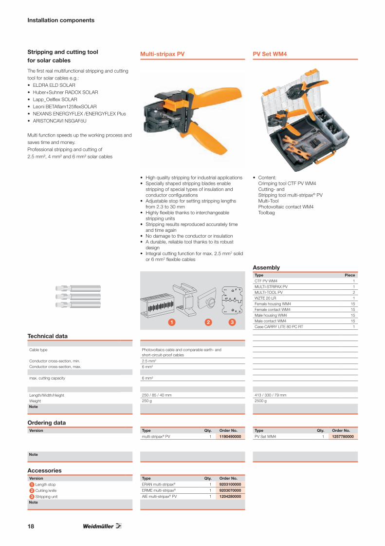
The first real multifunctional stripping and cutting tool for solar cables e.g.:• ELDRA ELD SOLAR• Huber+Suhner RADOX SOLAR• Lapp_Oelflex SOLAR• Leoni BETAflam125flexSOLAR• NEXANS ENERGYFLEX /ENERGYFLEX Plus• ARISTONCAVI NSGAFöU
Multi function speeds up the working process and saves time and money.Professional stripping and cutting of2.5 mm², 4 mm² and 6 mm² solar cables
Multi-stripax PV
Installation components
PV Set WM4
1 2 3
Stripping and cutting tool for solar cables
Technical data
Cable type
Conductor cross-section, min.Conductor cross-section, max.
max. cutting capacity
Length/Width/HeightWeightNote
Ordering dataVersion
Note
• High quality stripping for industrial applications • Specially shaped stripping blades enable
stripping of special types of insulation and conductor configurations
• Adjustable stop for setting stripping lengths from 2.3 to 30 mm
• Highly flexible thanks to interchangeable stripping units
• Stripping results reproduced accurately time and time again
• No damage to the conductor or insulation• A durable, reliable tool thanks to its robust
design• Integral cutting function for max. 2.5 mm2 solid
or 6 mm2 flexible cables
Photovoltaics cable and comparable earth- and short-circuit-proof cables
2.5 mm2
6 mm2
6 mm²
250 / 85 / 40 mm250 g
Type Qty. Order No.
multi-stripax® PV 1 1190490000
• Content: Crimping tool CTF PV WM4 Cutting- and Stripping tool multi-stripax® PVMulti-Tool Photovoltaic contact WM4 Toolbag
Type PieceCTF PV WM4 1
MULTI-STRIPAX PV 1MULTI-TOOL PV 2WZTE 20 LR 1Female housing WM4 15Female contact WM4 15Male housing WM4 15Male contact WM4 15Case CARRY LITE 80 PC RT 1
413 / 330 / 79 mm2500 g
Type Qty. Order No.
PV Set WM4 1 1257780000
AccessoriesVersion
1 Length stop
2 Cutting knife
3 Stripping unitNote
Type Qty. Order No.
ERAN multi-stripax® 1 9203100000
ERME multi-stripax® 1 9203070000
AIE multi-stripax® PV 1 1204280000
Assembly
18

Crimping tools for photovoltaic contacts
CTF PV WM4
Installation components
CTX PV
• Ratchet for precise crimping.• Release option in the event of incorrect
operation• With locator for exact positioning of the
contacts.
Technical dataDescription of contactType of contactCrimping range mm²
Tool dataLength mmWeight g
Note
Ordering dataVersion
Note
1.5...6 mm²
• For the Weidmüller photovoltaic connector WM4 and identical connectors
• For Multi-Contact MC4 1.5 mm² - 6 mm² and compatible plugs
• For Hirschmann SunCon 4mm² and compatible plugs
Photovoltaic connector WM4F-plug / -sleeve1.5...6
250730
Type Qty. Order No.
CTF PV WM4 1 1222870000
2.5...6 mm²
• For solar contacts from Tyco Solarlok 2.5 mm2, 4 mm2 und 6 mm2 and compatible plugs
• Multi-Contact MC3 2.5 mm2, 4 mm2 and 6 mm2
and compatible plugs
Photovoltaic connector for Solarlok and MC3
Machined contacts2.5...6
250730
Type Qty. Order No.
CTX PV 1 1249710000
19

Monitoring systems
System monitoring using Transclinic xi+
Page 28-32
Monitoring systems
20

Monitoring systems
Panel monitoring using CLINICS SOLAR
Page 22-26
PV plant software
Page 34-35
21

The smart way to monitor panels
Each PV plant is individual and that is why a site-specific installation is required to maximise profits. Partial shading, cracks in panels and mismatching issues can all significantly decrease the profit even when the ambient conditions are excellent.
CLINICS SOLAR products provide an intelligent way for analysis, diagnostics and optimisation of photovoltaic systems. The optimisation measures determined can increase the efficiency of plants and help produce a better return.
With CLINICS SOLAR you can monitor and evaluate all of the key parameters and the total output of a PV panel or string in a running system.
Designed for harsh environments with IP67 degree of protection.
Monitoring systems
Panel monitoring using CLINICS SOLAR
IP67
The CLINICS SOLAR product line can also be integrated easily and quickly into existing plants. The values can be exported over a wireless connection.
Simple and quick
IP67 degree of protection
22

-2
0
2
4
6
8
10
12
14
16
18
20
0 50 100 150 200 250 300
Seri e1
Seri e2
Seri e3
Seri e4
Seri e5
Seri e6
Seri e7
Seri e8
Seri e9
Seri e10
Seri e11
Seri e12
Seri e13
Seri e14
Seri e15
Seri e16
Seri e17
Seri e18
Seri e19
Seri e20
Seri e21
Seri e22
Seri e23
Seri e24
Seri e25
Seri e26
0
1
2
3
4
5
6
7
8
9
10
11
12
13
14
15
16
17
18
19
0 25 50 75 100 125 150 175 200 225 250 275 300 325
Voltld 2
Voltld
Voltld
Voltld
Voltld
Voltld
Voltld
Voltld
Voltld
Voltld
Voltld
Voltld
Voltld
Voltld
Voltld
Voltld
Voltld
Voltld
Voltld
Voltld
Voltld
Voltld
Voltld
Voltld
26
3
4
5
7
13
12
11
10
9
8
14
15
16
17
18
19
25
24
23
22
21
20
Optimisation with CLINICS SOLARAnalysis results
Total optimisation
The performance of the plant is increased with an analysis-optimised wiring system.
The system saves energy by powering itself via the photovoltaic panels. Thus is no need for an auxiliary power supply or for an additional wiring.
Energy efficient
The safe measuring method used is not dependent on the type of photovoltaic panels (mono- or polycrystalline or thin-film panels) or the inverter type.
Independent of modules or manufacturers
Monitoring systems
Energy
Quick, versatile on-site troubleshooting:with simple integration into existingplants using standard connector types.
Flexible usage
23

Performance reduction in a PV system
Performance in PV systems can be degraded due to different causes:
The performance drop in a PV system can be caused by a single faulty panel which could affect a complete string.
PV system total performance
Leistungskurven der einzelnen Module (Ausgangszustand)
Dirt/Pollution Shadowing Panel cracksCell breakage,
defective electronics
other faults e.g. cable damage
Data analysis
On the PC the software SOFTCLINIC determine the status of the photovoltaic panels quickly and reliably.
Data receiver
RECLINIC USB receives all the data sent by the TRANSCLINIC VI50 modules and transfers them via a USB port to a PC.
CLINICS SOLAR – Optimise performance by analysis
Clever trouble shooting with CLINICS SOLAR
Each photovoltaic panel to be tested (or the whole string) is connected using a simple Plug & Play Transclinic VI50 transmitter, this transmits the performance data of the panel for evaluation on a PC.
Monitoring systems
• Measurements during operation (real conditions)
• Simultaneous measurements of all the panels in the string over the desired period of time
• Visual indication by LEDs on device
• Wireless transmission of the measured values to a PC
24

Quick and easy trouble shooting in just two steps
In the first step towards localising the fault, the individual strings are analysed.
In the second step, a Transclinic VI50 is attached to each photovoltaic panel in that string to localise the fault on panel level.
Total power string 1
Total power string 1
Individual power of the photovoltaic panels
Total power string 2
Data collector
TRANSCLINIC VI50 are connected to the PV panels using a standard photovoltaic connector. It measures the voltage of the photovoltaic panel and the current in the string. It is powered by the photovoltaic panel.
Yield optimisation
After each fault is detected, appropriate actions can be taken which provides a simple and cheap way to increase the total performance of the system.
CLINICS SOLAR provides an easy and quick way to ensure a long-term yield from the photovoltaic plant, without a large investment.
• Panel repair• Cleaning• Replacement• New grouping of panels to a
string Faulty photovoltaic panels are taken
out of the strings and new grouping of panels to a string to avoid mismatching. In this way the performance can be optimised without having to replace the panel or purchase a new one.
Performance graphs of the individual PV modules following optimisation
Monitoring systems
25

TRANSCLINIC VI 50
TRANSCEIVER for measuring voltage and current for photovoltaic panels.
TRANSCLINIC VI 50 measures the voltage and current of the photovoltaic panel to which it is connected. It is powered through the photovoltaic panel and its consumption is minimum, so it doesn‘t affect the efficiency of the system.
TRANSCLINIC VI 50 shows locally the status of the photovoltaic panel through 3 LEDs.
Main features
Measurement voltage and current
Voltage visual indication through 3 high luminosity LEDs
No extra power needed, self powered through photovoltaic panel
RF transmission
IP 67Note
-20 ºC … +60 ºC
868 MHz, FSK modulation (for the EU area)
7 dBm
-110 dBm, AFC, DQD
9.600 bps
Less than 30 mA
IP67 resign encapsulated
105 x 73 x 31 mm
10-65 V DC 0-12 A
Type Qty. Order No.TRANSCLINIC VI 50 1 1175050000
Technical dataTechnology16 bits RISC CPU @ 40MHz
Temperature range
RF Interface
Bandwidth
Pmax transmission
Sensitivity
Transmission speed
Power
Input current
Degree of protection
Dimension (L x W x H)
Measurement range
Note
Ordering data
Note
RECLINIC USB
TRANSCEIVER RF USB
RECLINIC USB has been designed to receive all data from TRANSCLINIC modules in each installation and send them to a PC through the USB port.
With a PC and the appropriate software SOFTCLINIC the data of up to 28 modules can be displayed and stored. The analyses are then available for use. This means you can quickly identify modules which are performing differently and initiate corrective action.
Combined with the TRANSCLINIC modules it allows to access very fast and safety the status of all photovoltaic panels in a photovoltaic plant.
Main features
Powered through the USB
Status LED
RF transmission
IP 67
This device connect TRANSCLINIC with a PCNote
-20 ºC … +60 ºC
868 MHz, FSK modulation (for the EU area)
7 dBm
-110 dBm, AFC, DQD
9.600 bps
IP67 resign encapsulated
105 x 73 x 31 mm
Type Qty. Order No.RECLINIC USB 1 1175040000
Technical dataTechnology16 bits RISC CPU @ 40MHz
Temperature range
RF Interface
Bandwidth
Pmax transmission
Sensitivity
Transmission speed
Degree of protection
Dimension (L x W x H)
Note
Ordering data
Note
Monitoring systems
26

27

System monitoring using Transclinic xi+
System for a permanent performance control of photovoltaic plants
The unlimited functionality of a photovoltaic plant is crucial for its efficiency. The Transclinic xi+ device series continuously calculates/determines the current coming from individual strings or string groups as well as the voltage in a photovoltaic plant thus allowing a very detailed monitoring. Disturbances that might cause a decrease in profits are thus identified and can be eliminated without delay.
Depending on the model, the Transclinic xi+ has between 4 and 14 inputs for measuring currents of up to 30 A per string. The current measuring is particularly reliable thanks to precise shunt resistances. The current and voltage measuring data are transmitted via MODBUS RS485 RTU. Evaluation and presentation of the data can be done using the PV Plant software (pages 34 to 35).
In addition to current and voltage, it is possible to control optional analogue and digital signals and to operate signalling devices via a digital output. The information obtained about the operational status provides a reliable monitoring mechanism for the photovoltaic facility, which will help you to optimise your yield.
The measuring of the string current is effected via precise shunt resistances in order to achieve high linearity.
Current measurement
This digital output can be operated remotely. Thus, for instance, it is possible to operate signal units in case of maintenance.
Digital output
Monitoring systems
28

Transclinic xi+ is suitable for a large range of temperatures thus allowing a safe operation in the combiner boxes. In addition to this it determines the current temperature of the PCB.
Temperature monitoring
Transclinic xi+ enables voltage measurements up to 1,000 V DC. In combination with the string currents, this allows the calculation of the generated output of a photovoltaic plant.
Voltage measurement
In addition to the analogue values of voltage, current and PCB temperature it is possible to utilise further analogue and digital signals. So, for instance, it is possible to monitor the status of the surge protection or to connect wind and irradiance sensors.
Analogue and digital inputs
Monitoring systems
+70 °C to–20 °C
29

Monitoring systems
Transclinic xi+ – permanent performance monitoring
S8
S7
S6
+
S5
S4
S3
S2
S1
IN1+
IN1–
24 V
0 V
IN2+
VIN
I IN GN
D
VIN
I IN GN
D
485+
485–
GN
D48
5
485+
485–
GN
D48
5
IN2–
Input DC–X1
X2
X4 X8X5X6X3X1
Modbus
X4X7
SW1
+
–
SW2
Output DC–
PV PANEL
INVERTER
Mod
bus
RS
485
RTU
Mod
bus
RS
485
RTU
Pow
er S
uppl
y 18
...36
VD
C
Ana
loge
inpu
t
Ana
loge
inpu
t
Dig
ital i
nput
Dig
ital o
utpu
t
TRANSCLINIC XI+
g g
+
–
Transclinic xi+
Transclinic xi+ circuit diagram
The aim of the monitoring function is to provide permanent monitoring of the system to allow timely action to be taken as soon as the processes are not working as desired. Using the Transclinic xi+ monitoring system Weidmüller has created a solution specially designed for photovoltaic systems that provides permanent performance monitoring.
Supplemented with the PV Plant software program which has a module to manage the data and one to visualise it online or off-line, which offers several ways to access the operating data of the photovoltaic facility. The information about the operating condition of a photovoltaic plant is a crucial factor in yield optimisation.
30

Monitoring systems
Full functionality of a photovoltaic system is critical in terms of its efficiency. In particular, the decreasing feed-in tariffs mean that it is highly important for the operators and investors that the system is functioning perfectly. As photovoltaic panels are connected in series in so-called strings, local incidents can often have wide reaching effects, either on the whole string or even on whole segments of strings which are connected together.
Performance reductionsThere are many possible influences that can be considered when thinking about the possible causes of performance reductions:
• Shadowing - Plants that grow over time - Errors during the layout of the system thanks to the shadow
cast from known obstacles (e.g. trees and parts of buildings) - Newly constructed buildings• Dirt / pollution - Plant pollen - Soot - Moss - Bird droppings• Decreasing panel properties - Resistance increase at solder points - Cell breakage - Impaired performance of diodes in junction boxes• Installation errors - Poorly fitted or missing cable lines / plug-in connectors• Other errors - Cable damage (e. g. animal bite) - Interference by unauthorised persons (e. g. theft)
Depending on the effects of the cause, the yield of the plant may decrease by more than 10% compared to when there is error-free operation. To prevent such losses in yield, Weidmüller offers an efficient monitoring solution with Transclinic xi+. The series continuously monitors the power from single strings or groups of strings as well as the voltage of a Photovoltaic system and thereby permits detailed monitoring of the system. Negative influences, which lead to reduced output, can be detected immediately allowing rapid repairs or adjustments to be made directly to the system.
Continuous string monitoringThe Transclinic xi+ devices are divided into a measuring PCB and a CPU PCB for data processing. With this set-up and depending on the model, it is possible to measure the values from between 4 and 14 strings, with a maximum current per string of 30 A. By detecting the performance in parallel of many strings, and deviations detected can be narrowed down to the affected string and its modules. The effort involved in fault elimination is therefore directly reduced. For comparative measurements of the modules in the affective strings, the Weidmüller analysis system CLINICS SOLAR can be used. Using it, any performance reducing panel can be easily detected, even when they appear normally externally.
Connecting additional devicesThe currents and voltages measured by the Transclinic xi+ are digitised on the CPU PCV and transmitted via an RS 485 interface using the MODBUS RTU protocol. Additionally, other freely selectable analogue and digital signals can be controlled and signalling devices operated via a digital output. This permits the surge protection to be monitored. This allows targeted, proactive planning of maintenance work, as it can be directly determined which spare parts are needed and where they need to be installed. In the same way, wind and light meters can be directly connected without having to have a separate BUS address with its own logic.
Temperature rangeSo that year round operation is possible even with widely fluctuating weather conditions, Transclinic xi+ gives reliable performance outside (built into a combiner boxes) for guaranteed continuous operation in temperatures ranging from -20 to +70 °C. Additional reliability comes from the fact that the current PCB temperature is always measured and available.
Simple system integrationTransclinic xi+ is mounted on a DIN rail in the combiner boxes, and consumes little power. To connect into customer specific IT structures, only the MODBUS signal needs to be fed in. The protocol stack is naturally included with delivery. For PC based systems, the monitoring data are transferred using a MODBUS converter to a USB port, and are available there for further processing.
31

Monitoring systems
Technical data
Maximum number of strings
Maximum current per string
Maximum voltage
Supply of modules
Temperature range
Communication
Analogue input
Number of analogue inputs
Digital input
Number of digital inputs
Digital output
Number of digital outputs
Maximum reading error
Dimensions (length/width/height)
Note
Ordering data
Note
4 7 8 14
30 A 20 A 30 A 20 A
1,000 V DC 1,000 V DC 1,000 V DC 1,000 V DC
19 - 36 V DC 19 - 36 V DC 19 - 36 V DC 19 - 36 V DC
-20 ... +70 °C -20 ... +70 °C -20 ... +70 °C -20 ... +70 °C
MODBUS RS485 RTU MODBUS RS485 RTU MODBUS RS485 RTU MODBUS RS485 RTU
0 ... +10 V or 0 ... 20 mA 0 ... +10 V or 0 ... 20 mA 0 ... +10 V or 0 ... 20 mA 0 ... +10 V or 0 ... 20 mA
2 2 2 2
0.5 V low, 15 ... 24 V high 0.5 V low, 15 ... 24 V high 0.5 V low, 15 ... 24 V high 0.5 V low, 15 ... 24 V high
2 2 2 2
max. 30 V DC/AC / 50 mA max. 30 V DC/AC / 50 mA max. 30 V DC/AC / 50 mA max. 30 V DC/AC / 50 mA
1 1 1 1
± 1 % ± 1 % 1 % 1 %
225 x 109.5 x 92.2 mm 265 x 109.5 x 92.2 mm 295 x 109.5 x 92.2 mm 370 x 109.5 x 92.2 mm
Type Qty. Order No.Transclinic 4i+ 1 1238100000
Transclinic 7i+ 1 1238110000
Transclinic 8i+ 1 1238120000
Transclinic 14i+ 1 1238130000
Transclinic 4i+ Transclinic 7i+ Transclinic 8i+ Transclinic 14i+Transclinic xi+
Transclinic xi+ in operation
TRANSCLINICXI+
MODBUS RS485 RTU
MODBUS RS485 RTUsupply 24 DC (+)supply 24 DC (–)
32

33

Monitoring systems
PV plant software
Smart software for collecting data and monitoring photovoltaic plants
The ideal addition to the Transclinic xi+ string monitoring, it consists of two program modules:
The configuration moduleThe configuration module allows you to easily integrate the devices and facility components to be monitored (device combiner boxes, inverters, meters, weather sensors, etc.). These components can then be organised, grouped and renamed as needed. The users can easily specify e-mail or SMS-text messages that are to be sent out automatically as an alarm to any specific group. The configuration module also accesses the data needed for monitoring the photovoltaic plant online.
The visualisation moduleThe visualisation module is used to view and save the online data that has been sent to the PC. The data describing the current states of the photovoltaic system can be saved in the mySQL database and displayed graphically to permit more detailed analysis. The data can also be exported as an Excel or PDF file and then be sent in an e-mail. It is also possible to administer the alarms and their acknowledgements; this permits the schedule of the corresponding service procedures to be accurately documented.
Many different devices, regardless of brand, can be integrated into PV-Plant. Using the RTU Modbus, the data from frequency inverters or weather sensors can be displayed and evaluated.
Universal and vendor-neutral
A clear tree based topology is used for the configuration. Values can be displayed and changed using drag and drop mouse clicks.
Intuitive configuration
The causes of the alarm (e.g., value deviation) and the alarm types (e.g., SMS-text, e-mail) can be configured flexibly.
Clearly arranged alarm controls
MODBUS RTU
34
Monitoring systems
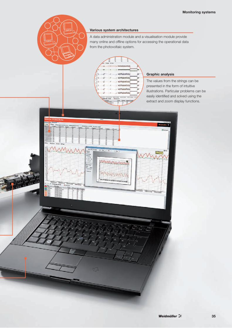
The values from the strings can be presented in the form of intuitive illustrations. Particular problems can be easily identified and solved using the extract and zoom display functions.
Graphic analysis
A data administration module and a visualisation module provide many online and offline options for accessing the operational data from the photovoltaic system.
Various system architectures
35

Combiner boxes and components
System monitoring using Transclinic xi+
Page 28-32
Marking system for photovoltaic plants
Page 130-140
Switched-mode power supply units - PRO-M - INSTAPOWER
Page 116-129
Combiner boxes and components
Professional tools for installation
Page 142-158
Professional tools for photovoltaic connectors and cables
Page 16-19
36

Combiner boxes and components
Surge protection
- for photovoltaic systems- for data and
communication devices
Page 58-84
WM4 photovoltaic connector
Page 12-14
Pre-wired combiner boxes
Page 38-56
Modular terminals
- Fuse terminals
- Feed-through terminals
- PE terminals
- Diode terminals
- Bolt-type screw terminals
- Supply terminals
Page 86-114
37
Pre-wired combiner boxes
Pre-wired combiner boxes
A perfect solution for every customer‘s requirements
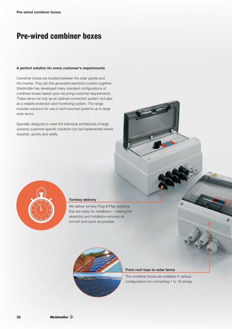
Combiner boxes are located between the solar panels and the inverter. They join the generated electrical currents together. Weidmüller has developed many standard configurations of combiner boxes based upon recurring customer requirements. These serve not only as an optimal connection system, but also as a reliable protection and monitoring system. The range includes solutions for use in roof-mounted systems up to large solar farms.
Specially designed to meet the individual architecture of large systems customer-specific solutions can be implemented where required, quickly and safely.
We deliver turnkey Plug-&-Play solutions that are ready for installation – making the assembly and installation process as smooth and quick as possible.
Turnkey delivery
The combiner boxes are available in various configurations for connecting 1 to 16 strings.
From roof-tops to solar farms
38

Pre-wired combiner boxes
Individual solutions
Be it a minor modification or a whole new individual product development, our application specialists develop and realise a tailored solution matching your individual requirements. Talk to us!
Weidmüller offers complete solutions for different requirements. Depending on the version the boxes can contain terminal blocks, surge protection, fuses and switch-disconnectors and even systems that permanently monitor the performance of the strings.
Optimally equipped
Depending on the version the boxes can be protected up to IP 66 which ensures that they are safe to use outdoors.
Reliable protectionIP 66
39

Pre-wired combiner boxes
The quick and optimum solution for roof mounted and industrial installations
The highest possible returns with the longest possible service life – this is the aim of every photovoltaic system operator. To achieve this target an efficient and error-free facility is essential. To protect photovoltaic plants, Weidmüller offers combiner boxes with surge protection components that can also be fitted with further functional components depending on the requirement.
Safety and system availability
In a photovoltaic system, the individual modules are connected together in series in so-called strings, that then go into combiner boxes which are fitted between the panels and the inverter. The strings of panels are joined together in combiner boxes and connected with DC main cabling, this then takes the electricity to the inverter.
As well as combining the strings, the combiner boxes can carry out various functions, including load isolation, surge protection and even permanent performance monitoring of individual strings or groups of strings.
Due to being configured with protection and monitoring components, a combiner box makes a major contribution to ensuring the system is efficient and fault-free. The system operator profits from higher returns and the longest possible service life of the system.
40

Pre-wired combiner boxes
Designed, manufactured and 100% tested in accordance with EN 61439-2
In the combiner boxes terminal blocks are used which Weidmüller has tested and approved using a special partial discharge test with DC voltage for 1,000 V DC applications. The surge protection components are also tested for use with 1,000 V DC, and effectively reduce interference-coupling caused by surge voltages.
All combiner boxes are tested and certified at Weidmüller‘s central laboratory according to EN 61439-2 for power switchgear and controlgear assemblies. They are also 100% tested after assembly.
This makes our installation-ready, plug-and-play solution the perfect system for connecting and protecting solar projects throughout Europe and beyond.
Solutions for all needs
Based on the comprehensive Weidmüller product range, the combiner boxes are offered with different equipment installed. Significant equipment features are fuse-holder terminals and terminal blocks, surge protection, load-break switches, cable connection technology and modules for monitoring the performance of the strings.
Fuse-holder terminals and terminal blocksSpecially for use in the PV area, Weidmüller offers terminals that have passed a certain insulation test. It is ensured that the terminals can withstand a voltage of 1,000 V DC under all climatic conditions. More information about the terminal blocks can be found from page 86.
Surge protectionThe surge protection with pluggable high-power varistors can be used in voltage ranges up to 1,000 V and therefore meets the higher demands of photovoltaic systems. More information about surge protection can be found from page 58.
Switch-disconnectorsTo isolate the DC side of a PV system, switch-disconnectors from other manufacturers are used. For repair and maintenance tasks, the voltage to the inverter can be turned off.
Cable connection technologyDepending on the version, the combiner boxes are delivered with cable glands or with WM4 PV connectors. The WM4 is compatible with all commonly available plug profiles and permits a quick and secure connection. More information about WM4 can be found from page 12.
String performance monitoringThe Transclinic xi+ device series continuously detects the current from individual strings or groups of strings and the voltage. Negative influences, which lead to reduced output, can be detected immediately. More information about Transclinic xi+ can be found from page 28.
41

Pre-wired combiner boxes
DC combiner boxes – product overview
AC combiner boxes – product overview
42
Number of strings Rated DC voltage
Rated DC current per input
Degree of protection
Surge protection DC switch-disconnector
Fuse holder for string wire protection
Cable gland (CG)/WM4 plug-in connector
String monitoring Part No: Part designation Technical data on page
1 1,000 V DC 30 A IP 66 • CG 7504811010 PV DC 1IN SPD CG 1,000 V 44
1 1,000 V DC 30 A IP 66 • WM 4 7504811001 PV DC 1IN SPD WM4 1,000 V 44
1+1 (for 2 MPPT) 1,000 V DC 30 A IP 66 • CG 7504811011 PV DC 1INx2 2MPPT 2SPD CG 1,000 V 45
1+1 (for 2 MPPT) 1,000 V DC 30 A IP 66 • WM 4 7504811002 PV DC 1INx2 2MMPT 2SPD WM4 1,000 V 45
2+2 (for 2 MPPT) 1,000 V DC 10 A IP 44 • • CG 7504811012 PV DC 2INx2 2SW 2MPPT 2SPD CG 1,000 V 45
2+2+2 (for 3 MPPT) 1,000 V DC 10 A IP 44 • • CG 7504811013 PV DC 2INx3 3SW 3MPPT 3SPD CG 1,000 V 46
3 1,000 V DC 12 A IP 66 • CG 7504811014 PV DC 3IN SPD CG 1,000 V 46
3 1,000 V DC 10 A IP 66 • WM 4 7504811005 PV DC 3IN SPD WM4 1,000 V 47
3 1,000 V DC 10 A IP 66 • • CG 7504811015 PV DC 3IN SW SPD CG 1,000 V 47
3 600 V DC 10 A IP 66 • • WM 4 7504811006 PV DC 3IN SW SPD WM4 600 V 47
4 1,000 V DC 11 A IP 66 • • • CG 7504811016 PV DC 4IN SW FH SPD CG 1,000 V 48
4 1,000 V DC 11 A IP 66 • • • WM 4 (inputs) / CG (outputs) 7504811007 PV DC 4IN SW FH SPD WM4 1,000 V 49
4 1,000 V DC 11 A IP 44 • • • CG • 7504811009 PV DC 4IN SW FH SPD CG 4i+ 1,000 V 48
4+2 (for 2 MPPT) 1,000 V DC 8 A IP 44 • • • CG 7504813008 PV DC 4+2IN 2SW 2MPPT FH 2SPD CG 1,000 V 49
8 1,000 V DC 12 A IP 55 • • • CG 7504813009 PV DC 8IN SW FH SPD CG 1,000 V 49
8 1,000 V DC 15 A IP 55 • • • CG • 7504813002 PV DC 8IN SW FH SPD CG 8i+ 1,000 V 50
12 1,000 V DC 13.3 A IP 55 • • • CG 7504813010 PV DC 12IN SW FH SPD CG 1,000 V 50
14 1,000 V DC 11.4 A IP 55 • • • CG • 7504813003 PV DC 14IN SW FH SPD CG 14i+ 1,000 V 51
16 1,000 V DC 10 A IP 55 • • • CG 7504813011 PV DC 16IN SW FH SPD CG 1,000 V 51
16 1,000 V DC 10 A IP 55 • • • CG • 7504813004 PV DC 16IN SW FH SPD CG 2x8i+ 1,000 V 51
Rated AC voltage
Rated AC current
Degree of protection
Surge protection Cable gland (CG)/WM4 plug-in connector
AC switch-disconnector (RCBO or RCD+MCB) Part No: Part designation Technical data on page
1 x single-phase 230 V AC 16 A IP 66 • CG RCBO: In=16A, 1P+N, Type A, curve C, IΔn=30mA (EN 61009-1) 7504812007 PV AC 1IN SW 230/16/30mA SPD CG 52
1 x single-phase 230 V AC 20 A IP 66 • CG RCBO: In=20A, 1P+N, Type A, curve C, IΔn=30mA (EN 61009-1) 7504812008 PV AC 1IN SW 230/20/30mA SPD CG 52
1 x single-phase 230 V AC 25 A IP 66 • CG RCBO: In=25A, 1P+N, Type A, curve C, IΔn=30mA (EN 61009-1) 7504812005 PV AC 1IN SW 230/25/30mA SPD CG 53
1 x single-phase 230 V AC 32 A IP 66 • CG RCBO: In=32A, 1P+N, Type A, curve C, IΔn=30mA (EN 61009-1) 7504812009 PV AC 1IN SW 230/32/30mA SPD CG 53
1 x single-phase 230 V AC 16 A IP 66 • CG RCBO: In=16A, 1P+N, Type A, curve C, IΔn=300mA (EN 61009-1) 7504812002 PV AC 1IN SW 230/16/300mA SPD CG 53
1 x single-phase 230 V AC 20 A IP 66 • CG RCBO: In=20A, 1P+N, Type A, curve C, IΔn=300mA (EN 61009-1) 7504812003 PV AC 1IN SW 230/20/300mA SPD CG 54
1 x single-phase 230 V AC 25 A IP 66 • CG RCBO: In=20A, 1P+N, Type A, curve C, IΔn=300mA (EN 61009-1) 7504812006 PV AC 1IN SW 230/25/300mA SPD CG 54
1 x single-phase 230 V AC 32 A IP 66 • CG RCBO: In=32A, 1P+N, Type A, curve C, IΔn=300mA (EN 61009-1) 7504812004 PV AC 1IN SW 230/32/300mA SPD CG 55
1 x three-phase 230 / 400 V AC 32 A IP 66 • CG RCD: In=40A, 4P, Type A, IΔn=300mA (EN 61008-1) MCB: In=32 A, 4P, curve C (EN 60898-1)
7504814001 PV AC 1IN 3P SW 230/32/300mA SPD CG 55

Pre-wired combiner boxes
43
Number of strings Rated DC voltage
Rated DC current per input
Degree of protection
Surge protection DC switch-disconnector
Fuse holder for string wire protection
Cable gland (CG)/WM4 plug-in connector
String monitoring Part No: Part designation Technical data on page
1 1,000 V DC 30 A IP 66 • CG 7504811010 PV DC 1IN SPD CG 1,000 V 44
1 1,000 V DC 30 A IP 66 • WM 4 7504811001 PV DC 1IN SPD WM4 1,000 V 44
1+1 (for 2 MPPT) 1,000 V DC 30 A IP 66 • CG 7504811011 PV DC 1INx2 2MPPT 2SPD CG 1,000 V 45
1+1 (for 2 MPPT) 1,000 V DC 30 A IP 66 • WM 4 7504811002 PV DC 1INx2 2MMPT 2SPD WM4 1,000 V 45
2+2 (for 2 MPPT) 1,000 V DC 10 A IP 44 • • CG 7504811012 PV DC 2INx2 2SW 2MPPT 2SPD CG 1,000 V 45
2+2+2 (for 3 MPPT) 1,000 V DC 10 A IP 44 • • CG 7504811013 PV DC 2INx3 3SW 3MPPT 3SPD CG 1,000 V 46
3 1,000 V DC 12 A IP 66 • CG 7504811014 PV DC 3IN SPD CG 1,000 V 46
3 1,000 V DC 10 A IP 66 • WM 4 7504811005 PV DC 3IN SPD WM4 1,000 V 47
3 1,000 V DC 10 A IP 66 • • CG 7504811015 PV DC 3IN SW SPD CG 1,000 V 47
3 600 V DC 10 A IP 66 • • WM 4 7504811006 PV DC 3IN SW SPD WM4 600 V 47
4 1,000 V DC 11 A IP 66 • • • CG 7504811016 PV DC 4IN SW FH SPD CG 1,000 V 48
4 1,000 V DC 11 A IP 66 • • • WM 4 (inputs) / CG (outputs) 7504811007 PV DC 4IN SW FH SPD WM4 1,000 V 49
4 1,000 V DC 11 A IP 44 • • • CG • 7504811009 PV DC 4IN SW FH SPD CG 4i+ 1,000 V 48
4+2 (for 2 MPPT) 1,000 V DC 8 A IP 44 • • • CG 7504813008 PV DC 4+2IN 2SW 2MPPT FH 2SPD CG 1,000 V 49
8 1,000 V DC 12 A IP 55 • • • CG 7504813009 PV DC 8IN SW FH SPD CG 1,000 V 49
8 1,000 V DC 15 A IP 55 • • • CG • 7504813002 PV DC 8IN SW FH SPD CG 8i+ 1,000 V 50
12 1,000 V DC 13.3 A IP 55 • • • CG 7504813010 PV DC 12IN SW FH SPD CG 1,000 V 50
14 1,000 V DC 11.4 A IP 55 • • • CG • 7504813003 PV DC 14IN SW FH SPD CG 14i+ 1,000 V 51
16 1,000 V DC 10 A IP 55 • • • CG 7504813011 PV DC 16IN SW FH SPD CG 1,000 V 51
16 1,000 V DC 10 A IP 55 • • • CG • 7504813004 PV DC 16IN SW FH SPD CG 2x8i+ 1,000 V 51
Rated AC voltage
Rated AC current
Degree of protection
Surge protection Cable gland (CG)/WM4 plug-in connector
AC switch-disconnector (RCBO or RCD+MCB) Part No: Part designation Technical data on page
1 x single-phase 230 V AC 16 A IP 66 • CG RCBO: In=16A, 1P+N, Type A, curve C, IΔn=30mA (EN 61009-1) 7504812007 PV AC 1IN SW 230/16/30mA SPD CG 52
1 x single-phase 230 V AC 20 A IP 66 • CG RCBO: In=20A, 1P+N, Type A, curve C, IΔn=30mA (EN 61009-1) 7504812008 PV AC 1IN SW 230/20/30mA SPD CG 52
1 x single-phase 230 V AC 25 A IP 66 • CG RCBO: In=25A, 1P+N, Type A, curve C, IΔn=30mA (EN 61009-1) 7504812005 PV AC 1IN SW 230/25/30mA SPD CG 53
1 x single-phase 230 V AC 32 A IP 66 • CG RCBO: In=32A, 1P+N, Type A, curve C, IΔn=30mA (EN 61009-1) 7504812009 PV AC 1IN SW 230/32/30mA SPD CG 53
1 x single-phase 230 V AC 16 A IP 66 • CG RCBO: In=16A, 1P+N, Type A, curve C, IΔn=300mA (EN 61009-1) 7504812002 PV AC 1IN SW 230/16/300mA SPD CG 53
1 x single-phase 230 V AC 20 A IP 66 • CG RCBO: In=20A, 1P+N, Type A, curve C, IΔn=300mA (EN 61009-1) 7504812003 PV AC 1IN SW 230/20/300mA SPD CG 54
1 x single-phase 230 V AC 25 A IP 66 • CG RCBO: In=20A, 1P+N, Type A, curve C, IΔn=300mA (EN 61009-1) 7504812006 PV AC 1IN SW 230/25/300mA SPD CG 54
1 x single-phase 230 V AC 32 A IP 66 • CG RCBO: In=32A, 1P+N, Type A, curve C, IΔn=300mA (EN 61009-1) 7504812004 PV AC 1IN SW 230/32/300mA SPD CG 55
1 x three-phase 230 / 400 V AC 32 A IP 66 • CG RCD: In=40A, 4P, Type A, IΔn=300mA (EN 61008-1) MCB: In=32 A, 4P, curve C (EN 60898-1)
7504814001 PV AC 1IN 3P SW 230/32/300mA SPD CG 55
44
Pre-wired combiner boxes
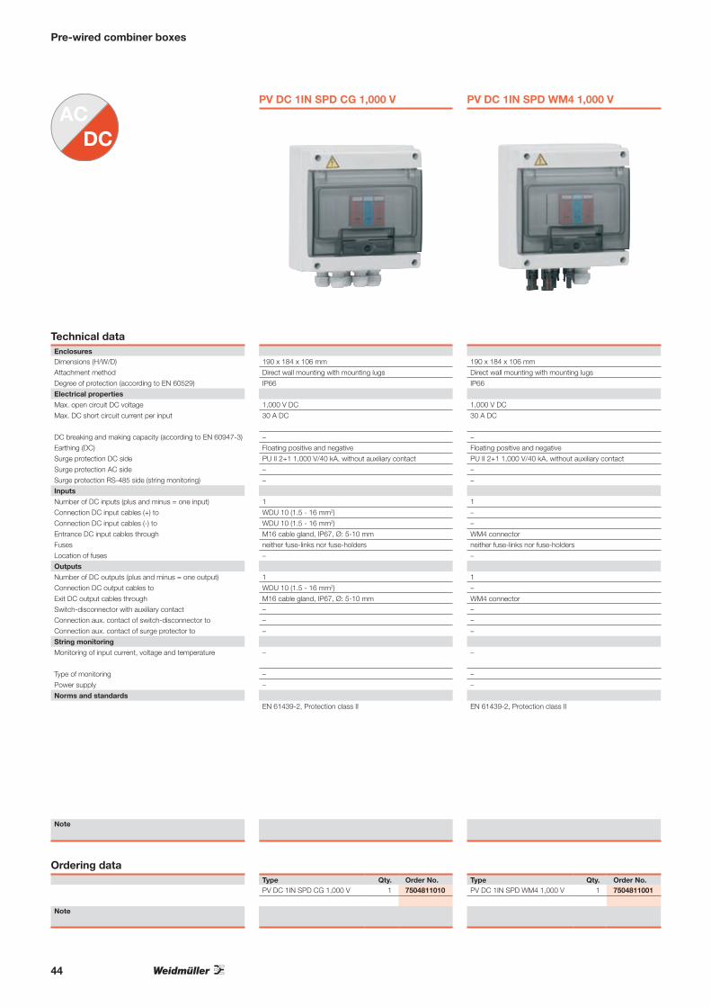
PV DC 1IN SPD CG 1,000 V PV DC 1IN SPD WM4 1,000 V
Technical dataEnclosuresDimensions (H/W/D) 190 x 184 x 106 mm 190 x 184 x 106 mm
Attachment method Direct wall mounting with mounting lugs Direct wall mounting with mounting lugs
Degree of protection (according to EN 60529) IP66 IP66
Electrical properties
Max. open circuit DC voltage 1,000 V DC 1,000 V DC
Max. DC short circuit current per input 30 A DC 30 A DC
DC breaking and making capacity (according to EN 60947-3) – –
Earthing (DC) Floating positive and negative Floating positive and negative
Surge protection DC side PU II 2+1 1,000 V/40 kA, without auxiliary contact PU II 2+1 1,000 V/40 kA, without auxiliary contact
Surge protection AC side – –
Surge protection RS-485 side (string monitoring) – –
Inputs
Number of DC inputs (plus and minus = one input) 1 1
Connection DC input cables (+) to WDU 10 (1.5 - 16 mm2) –
Connection DC input cables (-) to WDU 10 (1.5 - 16 mm2) –
Entrance DC input cables through M16 cable gland, IP67, Ø: 5-10 mm WM4 connector
Fuses neither fuse-links nor fuse-holders neither fuse-links nor fuse-holders
Location of fuses – –
Outputs
Number of DC outputs (plus and minus = one output) 1 1
Connection DC output cables to WDU 10 (1.5 - 16 mm2) –
Exit DC output cables through M16 cable gland, IP67, Ø: 5-10 mm WM4 connector
Switch-disconnector with auxiliary contact – –
Connection aux. contact of switch-disconnector to – –
Connection aux. contact of surge protector to – –
String monitoring
Monitoring of input current, voltage and temperature – –
Type of monitoring – –
Power supply – –
Norms and standards
EN 61439-2, Protection class II EN 61439-2, Protection class II
Note
Ordering dataType Qty. Order No. Type Qty. Order No.PV DC 1IN SPD CG 1,000 V 1 7504811010 PV DC 1IN SPD WM4 1,000 V 1 7504811001
Note

45
Pre-wired combiner boxes
PV DC 1INx2 2MPPT 2SPD CG 1,000 V PV DC 1INx2 2MPPT 2SPD WM4 1,000 V PV DC 2INx2 2SW 2MPPT 2SPD CG 1,000 V
250 x 256 x 140 mm 250 x 256 x 140 mm 360 x 360 x 171 mm
Direct wall mounting with mounting lugs Direct wall mounting with mounting lugs Direct wall mounting with mounting lugs
IP66 IP66 IP44
1,000 V DC 1,000 V DC 1,000 V DC
30 A DC 30 A DC 10 A DC
– – 2 x 32 A (DC21B 1,000 V)
Floating positive and negative Floating positive and negative Floating positive and negative
PU II 2+1 1,000 V/40 kA, without auxiliary contact PU II 2+1 1,000 V/40 kA, without auxiliary contact PU II 2+1 1,000 V/40 kA, without auxiliary contact
– – –
– – –
1+1 (for inverters with 2 MPPT) 1+1 (for inverters with 2 MPPT) 2+2 (for inverters with 2 MPPT)
WDU 10 (1.5 - 16 mm2) – WDU 10 (1.5 - 16 mm²)
WDU 10 (1.5 - 16 mm2) – WDU 10 (1.5 - 16 mm²)
M16 cable gland, IP67, Ø: 5-10 mm WM4 connector M16 cable gland, IP67, Ø: 5-10 mm
neither fuse-links nor fuse-holders neither fuse-links nor fuse-holders neither fuse-links nor fuse-holders
– – –
1+1 (for inverters with 2 MPPT) 1+1 (for inverters with 2 MPPT) 1+1 (for inverters with 2 MPPT)
WDU 10 (1.5 - 16 mm2) – WDU 16 (1.5 - 16 mm2)
M16 cable gland, IP67, Ø: 5-10 mm WM4 connector M20 cable gland, IP67, Ø: 6-12 mm
– – no
– – –
– – –
– – –
– – –
– – –
EN 61439-2, Protection class II EN 61439-2, Protection class II EN 61439-2, Protection class II
Type Qty. Order No. Type Qty. Order No. Type Qty. Order No.PV DC 1INx2 2MPPT 2SPD CG 1,000 V 1 7504811011 PV DC 1INx2 2MPPT 2SPD WM4 1,000 V 1 7504811002 PV DC 2INx2 2SW 2MPPT 2SPD CG 1,000 V 1 7504811012

46
PV DC 2INx3 3SW 3MPPT 3SPD CG 1,000 V PV DC 3IN SPD CG 1,000 V
Technical dataEnclosuresDimensions (H/W/D) 360 x 540 x 171 mm 250 x 256 x 140 mm
Attachment method Direct wall mounting with mounting lugs Direct wall mounting with mounting lugs
Degree of protection (according to EN 60529) IP44 IP66
Electrical properties
Max. open circuit DC voltage 1,000 V DC 1,000 V DC
Max. DC short circuit current per input 10 A DC 12 A DC
DC breaking and making capacity (according to EN 60947-3) 3 x 32 A (DC21B 1,000 V) –
Earthing (DC) Floating positive and negative Floating positive and negative
Surge protection DC side PU II 2+1 1,000 V/40 kA, without auxiliary contact PU II 2+1 1,000 V/40 kA, without auxiliary contact
Surge protection AC side – –
Surge protection RS-485 side (string monitoring) – –
Inputs
Number of DC inputs (plus and minus = one input) 2+2+2 (for inverters with 3 MPPT) 3
Connection DC input cables (+) to WDU 10 (1.5 - 16 mm²) WDU 10 (1.5 - 16 mm2)
Connection DC input cables (-) to WDU 10 (1.5 - 16 mm²) WDU 10 (1.5 - 16 mm2)
Entrance DC input cables through M16 cable gland, IP67, Ø: 5-10 mm M16 cable gland, IP67, Ø: 5-10 mm
Fuses neither fuse-links nor fuse-holders neither fuse-links nor fuse-holders
Location of fuses – –
Outputs
Number of DC outputs (plus and minus = one output) 1+1+1 (for inverters with 3 MPPT) 1
Connection DC output cables to WDU 16 (1.5 - 16 mm2) WDU 10 (1.5 - 16 mm2)
Exit DC output cables through M20 cable gland, IP67, Ø: 6-12 mm M16 cable gland, IP67, Ø: 5-10 mm
Switch-disconnector with auxiliary contact no –
Connection aux. contact of switch-disconnector to – –
Connection aux. contact of surge protector to – –
String monitoring
Monitoring of input current, voltage and temperature – –
Type of monitoring – –
Power supply – –
Norms and standards
EN 61439-2, Protection class II EN 61439-2, Protection class II
Note
Ordering dataType Qty. Order No. Type Qty. Order No.PV DC 2INx3 3SW 3MPPT 3SPD CG 1,000 V 1 7504811013 PV DC 3IN SPD CG 1,000 V 1 7504811014
Note
Pre-wired combiner boxes

47
PV DC 3IN SPD WM4 1,000 V PV DC 3IN SW SPD CG 1,000 V PV DC 3IN SW SPD WM4 600V
250 x 256 x 140 mm 250 x 328 x 140 mm 250 x 256 x 140 mm
Direct wall mounting with mounting lugs Direct wall mounting with mounting lugs Direct wall mounting with mounting lugs
IP66 IP66 IP66
1,000 V DC 1,000 V DC 600 V DC
10 A DC 10 A DC 10 A DC
– 32 A (DC21B 1,000 V) 32 A (DC21B 600 V)
Floating positive and negative Floating positive and negative Floating positive and negative
PU II 2+1 1,000 V/40 kA, without auxiliary contact PU II 2+1 1,000 V/40 kA, without auxiliary contact PU II 2+1 1,000 V/40 kA, without auxiliary contact
– – –
– – –
3 3 3
– WDU 10 (1.5 - 16 mm2) –
– WDU 10 (1.5 - 16 mm2) –
WM4 connector M16 cable gland, IP67, Ø: 5-10 mm WM4 connector
neither fuse-links nor fuse-holders neither fuse-links nor fuse-holders neither fuse-links nor fuse-holders
– – –
1 1 1
– WDU 16N (1,5 - 16 mm2) –
WM4 connector M20 cable gland, IP67, Ø: 6-12 mm WM4 connector
– – –
– – –
– – –
– – –
– – –
– – –
EN 61439-2, Protection class II EN 61439-2, Protection class II EN 61439-2, Protection class II
Type Qty. Order No. Type Qty. Order No. Type Qty. Order No.PV DC 3IN SPD WM4 1,000 V 1 7504811005 PV DC 3IN SW SPD CG 1,000 V 1 7504811015 PV DC 3IN SW SPD WM4 600V 1 7504811006
Pre-wired combiner boxes

48
PV DC 4IN SW FH SPD CG 1,000 V PV DC 4IN SW FH SPD CG 4i+ 1,000 V
Technical dataEnclosuresDimensions (H/W/D) 400 x 256 x 140 mm 540 x 540 x 171 mm
Attachment method Direct wall mounting with mounting lugs Direct wall mounting with mounting lugs
Degree of protection (according to EN 60529) IP66 IP44
Electrical properties
Max. open circuit DC voltage 1,000 V DC 1,000 V DC
Max. DC short circuit current per input 11 A DC 11 A DC
DC breaking and making capacity (according to EN 60947-3) 45 A (DC21B 1,000 V) 45 A (DC21B 1,000 V)
Earthing (DC) Floating positive and negative Floating positive and negative
Surge protection DC side PU II 2+1 1,000 V/40 kA, without auxiliary contact PU II 2+1R 1,000 V/40 kA, auxiliary contact
Surge protection AC side – PU II 1+1R 280 V/40 kA, auxiliary contact
Surge protection RS-485 side (string monitoring) – yes, without auxiliary contact
Inputs
Number of DC inputs (plus and minus = one input) 4 4
Connection DC input cables (+) to WSI 25/1 fuse holder (0.75 mm2 - 25 mm2) WSI 25/1 fuse holder (0.75 mm2 - 25 mm2)
Connection DC input cables (-) to WSI 25/1 fuse holder (0.75 mm2 - 25 mm2) WSI 25/1 fuse holder (0.75 mm2 - 25 mm2)
Entrance DC input cables through M16 cable gland, IP67, Ø: 5-10 mm M16 cable gland, IP67, Ø: 5-10 mm
Fuses empty fuse holders empty fuse holders
Location of fuses positive and negative inputs positive and negative inputs
Outputs
Number of DC outputs (plus and minus = one output) 1 1
Connection DC output cables to WDU 35N (2.5 - 35 mm2) WDU 35 (2.5 - 35 mm2)
Exit DC output cables through M20 cable gland, IP67, Ø: 10-14 mm M20 cable gland, IP67, Ø: 6-12 mm
Switch-disconnector with auxiliary contact – no
Connection aux. contact of switch-disconnector to – –
Connection aux. contact of surge protector to – at the digital input of the Transclinic xi+
String monitoring
Monitoring of input current, voltage and temperature – Transclinic 4i+
Type of monitoring – Individual inputs
Power supply – 85-264 Vac -> 24 Vdc (ref. 8739140000)
Norms and standards
EN 61439-2, Protection class II EN 61439-2, Protection class II
Note
Ordering dataType Qty. Order No. Type Qty. Order No.PV DC 2INx3 3SW 3MPPT 3SPD CG 1,000 V 1 7504811016 PV DC 4IN SW FH SPD CG 4i+ 1,000 V 1 7504811009
Note
Pre-wired combiner boxes

49
PV DC 4IN SW FH SPD WM4 1,000 V PV DC 4+2IN 2SW 2MPPT FH 2SPD CG 1,000 V PV DC 8IN SW FH SPD CG 1,000 V
400 x 328 x 140 mm 540 x 360 x 171 mm 600 x 500 x 230 mm
Direct wall mounting with mounting lugs Direct wall mounting with mounting lugs Mounting lugs
IP66 IP44 IP55
1,000 V DC 1,000 V DC 1,000 V DC
11 A DC 8.0 A + 6.25 A DC when 4+2 inputs are used
10.6 A + 12.5 A DC when 3+1 inputs are used
12 A DC
45 A (DC21B 1,000 V) 32 A (DC21A 1,000 V)+ 16 A (DC21A 1,000 V) 160 A (DC21B 1,000 V)
Floating positive and negative Floating positive and negative Floating positive and negative
PU II 2+1 1,000 V/40 kA, without auxiliary contact 2 x PU II 2+1 1,000 V/40 kA, without auxiliary contact PU II 2+1 1,000 V/40 kA, without auxiliary contact
– – –
– – –
4 4+2 (for inverters with 2 MPPT) 8
– WSI 25/1 fuse holder (0,75 mm2 - 25 mm2) /
WDU 10 (1,5 - 16 mm²)
WSI 25/1 fuse holder (0,75mm2 - 25 mm2)
– WSI 25/1 fuse holder (0,75 mm2 - 25 mm2) /
WDU 10 (1,5 - 16 mm²)
WSI 25/1 fuse holder (0,75 mm2 - 25 mm2)
WM4 connector M16 cable gland, IP67, Ø: 5-10 mm M16 cable gland, IP67, Ø: 5-10 mm
empty fuse holders empty fuse holders on 1st MPPT/no fuse holders on 2nd MPPT empty fuse holders
positive and negative inputs positive and negative inputs only for one MPPT positive and negative inputs
1 1+1 (for inverters with 2 MPPT) 1
WDU 35N (2.5 - 35 mm2) WFF 35 (< 50 mm2) WFF 70 (<95 mm²)
M20 cable gland, IP67, Ø: 10-14 mm M25 cable gland, IP67, Ø: 13-18 mm M25 cable gland, IP67, Ø: 13-18 mm
– no no
– – –
– – –
– – –
– – –
– – –
EN 61439-2, Protection class II EN 61439-2, Protection class II EN 61439-2, Protection class II
Type Qty. Order No. Type Qty. Order No. Type Qty. Order No.PV DC 4IN SW FH SPD WM4 1,000 V 1 7504811007 PV DC 4+2IN 2SW 2MPPT FH 2SPD CG 1,000 V 1 7504813008 PV DC 8IN SW FH SPD CG 1,000 V 1 7504813009
Pre-wired combiner boxes

50
PV DC 8IN SW FH SPD CG 8i+ 1,000 V PV DC 12IN SW FH SPD CG 1,000 V
Technical dataEnclosuresDimensions (H/W/D) 800 x 600 x 300 mm 800 x 600 x 300 mm
Attachment method Mounting lugs Mounting lugs
Degree of protection (according to EN 60529) IP55 IP55
Electrical properties
Max. open circuit DC voltage 1,000 V DC 1,000 V DC
Max. DC short circuit current per input 15 A DC 13.3 A DC
DC breaking and making capacity (according to EN 60947-3) 160 A (DC21B 1,000 V) 160 A (DC21B 1,000 V)
Earthing (DC) Floating positive and negative Floating positive and negative
Surge protection DC side PU II 2+1R 1,000 V/40 kA, auxiliary contact PU II 2+1 1,000 V/40 kA, without auxiliary contact
Surge protection AC side PU II 1+1R 280 V/40 kA, auxiliary contact –
Surge protection RS-485 side (string monitoring) yes, without auxiliary contact –
Inputs
Number of DC inputs (plus and minus = one input) 8 12
Connection DC input cables (+) to WSI 25/1 fuse holder (0,75 mm2 - 25 mm2) WSI 25/1 fuse holder (0,75 mm2 - 25 mm2)
Connection DC input cables (-) to WSI 25/1 fuse holder (0,75 mm2 - 25 mm2) WSI 25/1 fuse holder (0,75 mm2 - 25 mm2)
Entrance DC input cables through M16 cable gland, IP67, Ø: 5-10 mm M16 cable gland, IP67, Ø: 5-10 mm
Fuses empty fuse holders empty fuse holders
Location of fuses positive and negative inputs positive and negative inputs
Outputs
Number of DC outputs (plus and minus = one output) 1 1
Connection DC output cables to WFF 70 (< 95 mm2) WFF 120 (< 150 mm2)
Exit DC output cables through M25 cable gland, IP67, Ø: 13-18 mm M32 cable gland, IP67, Ø: 18-25 mm
Switch-disconnector with auxiliary contact yes no
Connection aux. contact of switch-disconnector to at the digital input of the Transclinic xi+ –
Connection aux. contact of surge protector to at the digital input of the Transclinic xi+ –
String monitoring
Monitoring of input current, voltage and temperature Transclinic 8i+ –
Type of monitoring Individual inputs –
Power supply 85-264 Vac -> 24 Vdc (ref. 8739140000) –
Norms and standards
EN 61439-2, Protection class II EN 61439-2, Protection class II
Note
Ordering dataType Qty. Order No. Type Qty. Order No.PV DC 8IN SW FH SPD CG 8i+ 1,000 V 1 7504813002 PV DC 12IN SW FH SPD CG 1,000 V 1 7504813010
Note
Pre-wired combiner boxes
51
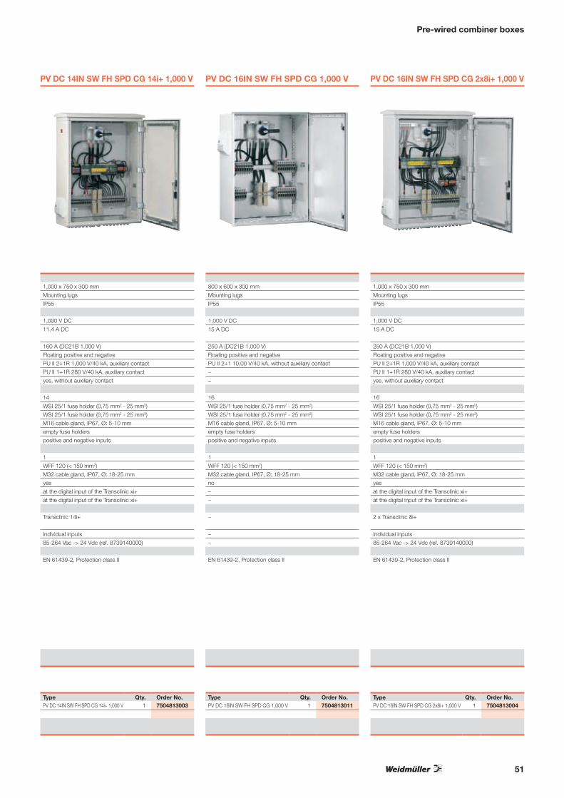
PV DC 14IN SW FH SPD CG 14i+ 1,000 V PV DC 16IN SW FH SPD CG 1,000 V PV DC 16IN SW FH SPD CG 2x8i+ 1,000 V
1,000 x 750 x 300 mm 800 x 600 x 300 mm 1,000 x 750 x 300 mm
Mounting lugs Mounting lugs Mounting lugs
IP55 IP55 IP55
1,000 V DC 1,000 V DC 1,000 V DC
11.4 A DC 15 A DC 15 A DC
160 A (DC21B 1,000 V) 250 A (DC21B 1,000 V) 250 A (DC21B 1,000 V)
Floating positive and negative Floating positive and negative Floating positive and negative
PU II 2+1R 1,000 V/40 kA, auxiliary contact PU II 2+1 10,00 V/40 kA, without auxiliary contact PU II 2+1R 1,000 V/40 kA, auxiliary contact
PU II 1+1R 280 V/40 kA, auxiliary contact – PU II 1+1R 280 V/40 kA, auxiliary contact
yes, without auxiliary contact – yes, without auxiliary contact
14 16 16
WSI 25/1 fuse holder (0,75 mm2 - 25 mm2) WSI 25/1 fuse holder (0,75 mm2 - 25 mm2) WSI 25/1 fuse holder (0,75 mm2 - 25 mm2)
WSI 25/1 fuse holder (0,75 mm2 - 25 mm2) WSI 25/1 fuse holder (0,75 mm2 - 25 mm2) WSI 25/1 fuse holder (0,75 mm2 - 25 mm2)
M16 cable gland, IP67, Ø: 5-10 mm M16 cable gland, IP67, Ø: 5-10 mm M16 cable gland, IP67, Ø: 5-10 mm
empty fuse holders empty fuse holders empty fuse holders
positive and negative inputs positive and negative inputs positive and negative inputs
1 1 1
WFF 120 (< 150 mm2) WFF 120 (< 150 mm2) WFF 120 (< 150 mm2)
M32 cable gland, IP67, Ø: 18-25 mm M32 cable gland, IP67, Ø: 18-25 mm M32 cable gland, IP67, Ø: 18-25 mm
yes no yes
at the digital input of the Transclinic xi+ – at the digital input of the Transclinic xi+
at the digital input of the Transclinic xi+ – at the digital input of the Transclinic xi+
Transclinic 14i+ – 2 x Transclinic 8i+
Individual inputs – Individual inputs
85-264 Vac -> 24 Vdc (ref. 8739140000) – 85-264 Vac -> 24 Vdc (ref. 8739140000)
EN 61439-2, Protection class II EN 61439-2, Protection class II EN 61439-2, Protection class II
Type Qty. Order No. Type Qty. Order No. Type Qty. Order No.PV DC 14IN SW FH SPD CG 14i+ 1,000 V 1 7504813003 PV DC 16IN SW FH SPD CG 1,000 V 1 7504813011 PV DC 16IN SW FH SPD CG 2x8i+ 1,000 V 1 7504813004
Pre-wired combiner boxes

52
PV AC 1IN SW 230/16/30mA SPD CG PV AC 1IN SW 230/20/30mA SPD CG
Technical dataEnclosuresDimensions (H/W/D) 190 x 184 x 106 mm 190 x 184 x 106 mm
Attachment method Direct wall mounting with mounting lugs Direct wall mounting with mounting lugs
Degree of protection (according to EN 60529) IP66 IP66
Electrical properties
Rated AC voltage (Un) 230 V AC 230 V AC
Rated AC current (In) 16 A AC 20 A AC
Residual current AC circuit-breaker (RCD) / Residual current
AC circuit breaker with overcurrent protection (RCBO)
RCBO: In=16A, 1P+N, Type A, curve C, IΔn=30mA
(EN 61009-1)
RCBO: In=20A, 1P+N, Type A, curve C, IΔn=30mA
(EN 61009-1)
Thermal magnetic AC circuit breaker RCBO RCBO
Earthing (AC) TN-S, TN-C-S, TT & IT (EN 60364) TN-S, TN-C-S, TT & IT (EN 60364)
Surge protection AC side PU II 1+1 280 V/40 kA, without auxiliary contact PU II 1+1 280 V/40 kA, without auxiliary contact
Inputs
Number of AC inputs, inverter side 1 x single-phase (L, N, PE) 1 x single-phase (L, N, PE)
Connection inverter side AC input cables to WDU 10 (1.5 - 16 mm²) WDU 10 (1.5 - 16 mm²)
Entrance inverter side AC input cables through M20 cable gland, IP67, Ø: 10-14 mm M20 cable gland, IP67, Ø: 10-14 mm
Outputs
Number of AC outputs, grid side 1 x single-phase (L, N, PE) 1 x single-phase (L, N, PE)
Connection grid side AC output cables to AC modular device (< 25 mm²) AC modular device (< 25 mm²)
Exit grid side AC output cables through M25 cable gland, IP67, Ø: 13-18 mm M25 cable gland, IP67, Ø: 13-18 mm
Standards
EN 61439-2, Protection class II EN 61439-2, Protection class II
Note
Ordering dataType Qty. Order No. Type Qty. Order No.PV AC 1IN SW 230/16/30mA SPD CG 1 7504812007 PV AC 1IN SW 230/20/30mA SPD CG 1 7504812008
Note
Pre-wired combiner boxes

53
PV AC 1IN SW 230/25/30mA SPD CG PV AC 1IN SW 230/32/30mA SPD CG PV AC 1IN SW 230/16/300mA SPD CG
190 x 184 x 106 mm 190 x 184 x 106 mm 190 x 184 x 106 mm
Direct wall mounting with mounting lugs Direct wall mounting with mounting lugs Direct wall mounting with mounting lugs
IP66 IP66 IP66
230 V AC 230 V AC 230 V AC
25 A AC 32 A AC 16 A AC
RCBO: In=25A, 1P+N, Type A, curve C, IΔn=30mA
(EN 61009-1)
RCBO: In=32A, 1P+N, Type A, curve C, IΔn=30mA
(EN 61009-1)
RCBO: In=16A, 1P+N, Type A, curve C, IΔn=300mA
(EN 61009-1)
RCBO RCBO RCBO
TN-S, TN-C-S, TT & IT (EN 60364) TN-S, TN-C-S , TT & IT (EN 60364) TN-S, TN-C-S, TT & IT (EN 60364)
PU II 1+1 280 V/40 kA, without auxiliary contact PU II 1+1 280 V/40 kA, without auxiliary contact PU II 1+1 280 V/40 kA, without auxiliary contact
1 x single-phase (L, N, PE) 1 x single-phase (L, N, PE) 1 x single-phase (L, N, PE)
WDU 10 (1.5 - 16 mm²) WDU 10 (1.5 - 16 mm²) WDU 10 (1.5 - 16 mm²)
M20 cable gland, IP67, Ø: 10-14 mm M20 cable gland, IP67, Ø: 10-14 mm M20 cable gland, IP67, Ø: 10-14 mm
1 x single-phase (L, N, PE) 1 x single-phase (L, N, PE) 1 x single-phase (L, N, PE)
AC modular device (< 25 mm²) AC modular device (< 25 mm²) AC modular device (< 25 mm²)
M25 cable gland, IP67, Ø: 13-18 mm M25 cable gland, IP67, Ø: 13-18 mm M25 cable gland, IP67, Ø: 13-18 mm
EN 61439-2, Protection class II EN 61439-2, Protection class II EN 61439-2, Protection class II
Type Qty. Order No. Type Qty. Order No. Type Qty. Order No.PV AC 1IN SW 230/25/30mA SPD CG 1 7504812005 PV AC 1IN SW 230/32/30mA SPD CG 1 7504812009 PV AC 1IN SW 230/16/300mA SPD CG 1 7504812002
Pre-wired combiner boxes

54
PV AC 1IN SW 230/20/300mA SPD CG PV AC 1IN SW 230/25/300mA SPD CG
Technical dataEnclosuresDimensions (H/W/D) 190 x 184 x 106 mm 190 x 184 x 106 mm
Attachment method Direct wall mounting with mounting lugs Direct wall mounting with mounting lugs
Degree of protection (according to EN 60529) IP66 IP66
Electrical properties
Rated AC voltage (Un) 230 V AC 230 V AC
Rated AC current (In) 20 A AC 25 A AC
Residual current AC circuit-breaker (RCD) / Residual current
AC circuit breaker with overcurrent protection (RCBO)
RCBO: In=20A, 1P+N, Type A, curve C, IΔn=300mA
(EN 61009-1)
RCBO: In=25A, 1P+N, Type A, curve C, IΔn=300mA
(EN 61009-1)
Thermal magnetic AC circuit breaker RCBO RCBO
Earthing (AC) TN-S, TN-C-S, TT & IT (EN 60364) TN-S, TN-C-S, TT & IT (EN 60364)
Surge protection AC side PU II 1+1 280 V/40 kA, without auxiliary contact PU II 1+1 280 V/40 kA, without auxiliary contact
Inputs
Number of AC inputs, inverter side 1 x single-phase (L, N, PE) 1 x single-phase (L, N, PE)
Connection inverter side AC input cables to WDU 10 (1.5 - 16 mm²) WDU 10 (1.5 - 16 mm²)
Entrance inverter side AC input cables through M20 cable gland, IP67, Ø: 10-14 mm M20 cable gland, IP67, Ø: 10-14 mm
Outputs
Number of AC outputs, grid side 1 x single-phase (L, N, PE) 1 x single-phase (L, N, PE)
Connection grid side AC output cables to AC modular device (< 25 mm²) AC modular device (< 25 mm²)
Exit grid side AC output cables through M25 cable gland, IP67, Ø: 13-18 mm M25 cable gland, IP67, Ø: 13-18 mm
Standards
EN 61439-2, Protection class II EN 61439-2, Protection class II
Note
Ordering dataType Qty. Order No. Type Qty. Order No.PV AC 1IN SW 230/20/300mA SPD CG 1 7504812003 PV AC 1IN SW 230/25/300mA SPD CG 1 7504812006
Note
Pre-wired combiner boxes
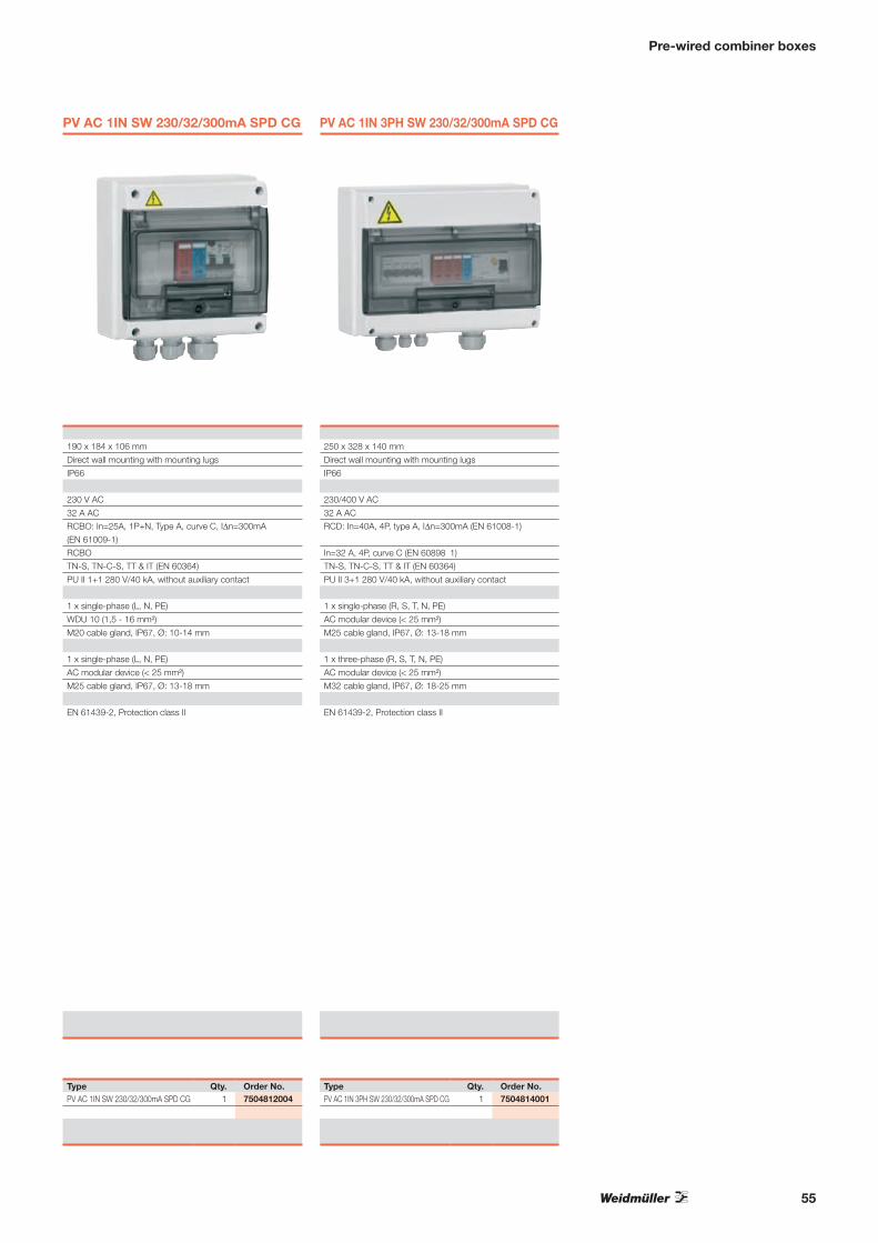
55
PV AC 1IN SW 230/32/300mA SPD CG PV AC 1IN 3PH SW 230/32/300mA SPD CG
190 x 184 x 106 mm 250 x 328 x 140 mm
Direct wall mounting with mounting lugs Direct wall mounting with mounting lugs
IP66 IP66
230 V AC 230/400 V AC
32 A AC 32 A AC
RCBO: In=25A, 1P+N, Type A, curve C, IΔn=300mA
(EN 61009-1)
RCD: In=40A, 4P, type A, IΔn=300mA (EN 61008-1)
RCBO In=32 A, 4P, curve C (EN 60898‐1)
TN-S, TN-C-S, TT & IT (EN 60364) TN-S, TN-C-S, TT & IT (EN 60364)
PU II 1+1 280 V/40 kA, without auxiliary contact PU II 3+1 280 V/40 kA, without auxiliary contact
1 x single-phase (L, N, PE) 1 x single-phase (R, S, T, N, PE)
WDU 10 (1,5 - 16 mm²) AC modular device (< 25 mm²)
M20 cable gland, IP67, Ø: 10-14 mm M25 cable gland, IP67, Ø: 13-18 mm
1 x single-phase (L, N, PE) 1 x three-phase (R, S, T, N, PE)
AC modular device (< 25 mm²) AC modular device (< 25 mm²)
M25 cable gland, IP67, Ø: 13-18 mm M32 cable gland, IP67, Ø: 18-25 mm
EN 61439-2, Protection class II EN 61439-2, Protection class II
Type Qty. Order No. Type Qty. Order No.PV AC 1IN SW 230/32/300mA SPD CG 1 7504812004 PV AC 1IN 3PH SW 230/32/300mA SPD CG 1 7504814001
Pre-wired combiner boxes

Inquiry form
Inquiry form for PV combiner boxesDate:_________________
Weidmüller GmbH & Co. KG
Tel. +49 5231 1428-0
Fax +49 5231 1428-116
www.weidmueller.de
Weidmüller Schweiz AG
Tel. +41 52 6740707
Fax +41 52 6740708
www.weidmueller.ch
Weidmüller Ges.m.b.H.
Tel. +43 2236 6708-0
Fax +43 2236 6708-199
www.weidmueller.at Master copy
56
Contact dataCompany name
Customer number at Weidmüller
Project name
Your name
Tel. (for any queries)
Name of your contact at Weidmüller
SpecificationsNumber of boxes in question
Number of strings
Fuses in Plus pole (+) Minus pole (-)
String current [A]
Max. rated DC voltage [V]
Total current [A]
Max. cross-section of the output terminals [mm²]
Max. cross-section of the string lines [mm²]
String cable entry PV WM4 connector Cable glands
Other cable entry / special features
Performance monitoring Transclinic xi+ Yes No
Existing external supply voltage
(required for Transclinic xi+) 24 V DC from outside 230 V AC from outside
Surge protection (OVP) Yes No
Switch-disconnector Yes No
Degree of protection (standard: IP55)
Attachment method Free-standing (floor distributors) Wall mounting
Lockable housing Yes No
Are special markers needed (e.g. cabinet
number in a park)
Further requirements
Environment / operating conditionsFor use Outdoors Inside
Operating manual language German English
Language spoken at the installation site German English
Other language
Notes

57

Surge protection for photovoltaic systems
High energy absorption with lmax: 40 kA (8/20 μm) and Uoc: 6 kV with short response time.High pulse currents with IImp up to a maximum of 30 kA (10/350 μs).
High leakage current
Lightning and surge protection for photovoltaic systems
Class I and II lightning and overvoltage protection
Weidmüller‘s surge protection type PU I protects low-voltage consumer installations and electronic devices against direct lightning effects and overvoltages that can occur through atmospheric discharges (thunderstorms) or by switching operations (transients).The PU I- and II-series meet the requirements of Class I and II in accordance with IEC 61643-1:2008 and the type 1 and type 2 comply with EN 61643-1.
Function indication, maintenance and homologationsThe PU II surge protection modules are provided with an optical control. The indicator is controlled by a thermal disconnection unit. If this unit has “answered”, there is no protection, so the colour of the indicator changes from green to red. A qualified person can replace the inoperative arrester without disconnecting the wiring. The pluggable varistor modules are coded in compliance with their voltage. Thus it is only possible to plug a suitable replacement varistor.
Easy and safe exchange due to coded modules and bases.
Pluggable and codable protection elements
58

Surge protection for photovoltaic systems
Covers the lightning protection level (LPL) I to IV as well as the network types TN-C, TN-S, IT, TT.
Great variety
V-TEST
Testing device for the control of the protective function for the following product families: PU I, PU II and VSPC according to IEC 62305 (periodical testing).
Easy connection to superordinate control and signalling of the protective function’s status.
Telecommunication contact (change-over)
Visual status indicator for detecting faults.
Visual function indicator
For further information, please ask for our catalogue:
Electronics – Surge protectionOrder No.: 1271290000
Ele
ktro
nik
– Ü
ber
span
nu
ng
ssch
utz
Kat
alo
g 2
011
Elektronik ÜberspannungsschutzKatalog
Bestellnummer:1271280000/01/2011/SMMD
www.weidmueller.com4.4
2011
4.4KA
TA
LOG
ÄgyptenArgentinienAserbaidschanAustralienBahrainBelgienBosnien undHerzegowinaBrasilienBulgarienChileChinaCosta RicaDänemarkDeutschlandEcuadorEstlandFinnlandFrankreichGriechenlandGroßbritannienHongkong IndienIndonesienIranIrlandIslandIsraelItalienJapanJordanien
KanadaKasachstanKatarKolumbienKoreaKroatienKuwaitLettlandLibanonLitauenLuxemburgMalaysiaMaltaMazedonienMexikoMoldauNeuseelandNiederlandeNorwegenOmanÖsterreichPakistanPeruPhilippinenPolenPortugalRumänienRusslandSaudi-ArabienSchwedenSchweiz
SerbienSingapurSlowakeiSlowenienSpanienSüdafrikaTaiwanThailandTschechienTunesienTürkeiUkraineUngarnUruguayUsbekistanVenezuelaVereinigteArabischeEmirateVereinigteStaatenVietnamWeißrussland
Weidmüller ist weltweit führender Anbieter vonLösungen für die elektrische Verbindung, Übertragungund Wandlung von Energie, Signalen und Daten imindustriellen Umfeld.
Das Unternehmen mit Hauptsitz in Detmold/Ostwestfalenentwickelt, produziert und vertreibt weltweit Produkteder elektrischen Verbindungstechnik und der Elektronik.Über ein Netzwerk von Applikationsspezialisten bietetWeidmüller Engineering-Dienstleistungen an undentwickelt anwendungsspezifische Lösungen.
Das gesamte Produkt- und Leistungsspektrum sichertunseren Kunden und Weidmüller in gleicher Weisedauerhaft Wettbewerbs- und Wertvorteile.
59

Surge protection for photovoltaic systems
Surge protection on the energy supply side
Lines can be charged with high currents and voltages following a lighting strike. This can lead to permanent damage and loss of the photovoltaic system. The use of lightning arresters and surge protection devices results in a higher system availability
and better profit. Weidmüller offers a complete range for protection in accordance with IEC 60364-7-712 for the energy input for both roof-mounted systems and large-scale systems.
External lightning protection available
then an internal lightning protector is required (Class I)
No external lightning protection available
then an overvoltage protection is sufficient (Class II)
In large-scale systems, the house shown
relates to the inverter housing in the field.
Can be used with higher requirements in terms of
availability and in public facilities
(Lightning protection level (LPL) I + II)
Can be used for domestic installation
and standard plants
(Lightning protection level (LPL) III + IV)
Sin
gle
-ph
ase
PU I 1+1 LCF 280V/30KAPage 68
PU I 1+1 280V/12,5KA *Page 65
PU II 1+1 280V/40kAPage 66
Th
ree-
ph
ase
TN
-S /
TT
/ IT
TN-S TT IT
PU I 3+1 LCF 280V/30KAPage 68
PU I 3+1 280V/12,5KA *Page 64
PU II 3+1 280V/40kAPage 66
TN
-C
TN-C
PU I 3 LCF 280V/30KAPage 69
PU I 3 280V/12,5KA *Page 65
PU II 3 280V/40KAPage 67
* leakage current free versions for installation in front of the meter can be found in TK 4.4
Ready-made standard solutionsWeidmüller offers an extensive range of pre-wired combiner boxes with surge protection devices for the AC side in 1- and 3-phase applications.
The complete overview of our standard solutions can be found on pages 52 to 55.
60
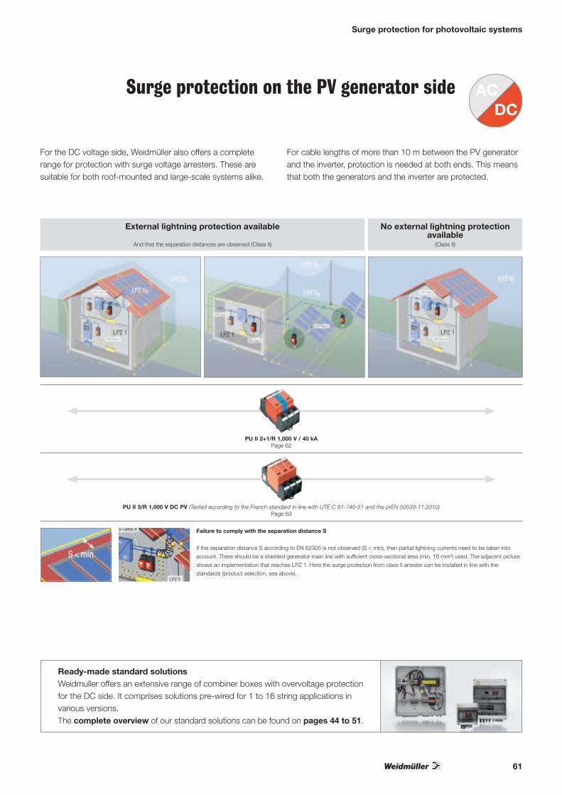
Surge protection for photovoltaic systems
Surge protection on the PV generator side
For the DC voltage side, Weidmüller also offers a complete range for protection with surge voltage arresters. These are suitable for both roof-mounted and large-scale systems alike.
For cable lengths of more than 10 m between the PV generator and the inverter, protection is needed at both ends. This means that both the generators and the inverter are protected.
External lightning protection available
And that the separation distances are observed (Class II)
No external lightning protection available
(Class II)
PU II 2+1/R 1,000 V / 40 kAPage 62
PU II 3/R 1,000 V DC PV (Tested according to the French standard in line with UTE C 61-740-51 and the prEN 50539-11:2010)Page 63
Ready-made standard solutionsWeidmuller offers an extensive range of combiner boxes with overvoltage protection for the DC side. It comprises solutions pre-wired for 1 to 16 string applications in various versions. The complete overview of our standard solutions can be found on pages 44 to 51.
Failure to comply with the separation distance S
If the separation distance S according to EN 62305 is not observed (S < min), then partial lightning currents need to be taken into
account. There should be a shielded generator main line with sufficient cross-sectional area (min. 16 mm²) used. The adjacent picture
shows an implementation that reaches LPZ 1. Here the surge protection from class II arrester can be installed in line with the
standards (product selection, see above).
61

Surge protection for photovoltaic systems (DC)
Technical data PV voltage to IEC 60364-7-712
max. continuous voltage, DC [(L+/L-) —>PE]
Nominal voltage
max. continuous voltage, Uc (DC)
Requirements class to IEC 61643-1
Rated discharge current (8/20 µs)
Limiting discharge current (8/20 µs)
Discharge current, max., max. (8/20 µs)
Response time
Protection level at In (Up
Protection level at 5kA (Up)
Temporary surge - UTOV
Optical function indicator
Signalling contact
Design
Ambient temperature (operational)
Storage temperature
Approvals
Dimensions
Clamping range (rating- / min. / max.) mm2
Length x width x height mmNote
Ordering dataVersion
without telecomm. contact
with telecomm. contact
Accessories
DC surge protection
Class II surge protection for photovoltaic applications
• plug-in arrestor top section
• high energy absorption with short time to sparkover
• insert can be rotated through 180°
• no follow current
• installed in installation boxes
• thermal protection
+ –PE
OK CHANGE OK CHANGE
14 1211
U U
PU II 2+1/R 1,000 V / 40 kA
≤ 1,000 V
900 V AC / 1,200 V DC
550 V
745 V
Class II
20 kA
40 kA
40 kA
≤ 25 ns
< 2650 V
< 1700 V
550 VV
green = OK; red = arrester faulty, replace
250 V 1A 1CO at PU II 2+1 R
3 unit widths; Installation housing
-40 … 80 °C
-40 … 85 °C
CE, ÖVE
without telecomm. contact with telecomm. contact
25 / 4 / 25 25 / 4 / 25
90 x 54 x 58 90 x 54 x 58* This product also fulfils the requirements for Class III with Uoc: 6 kV
Type Qty. Order No.PU II 2+1 1,000 V DC 1 8882340001
PU II 2+1R 1,000 V DC 1 8882350001
Plug-in spare arrester PU II 0 – 8860120000 Plug-in spare arrester PU II 0 N-PE – 8871940000
62
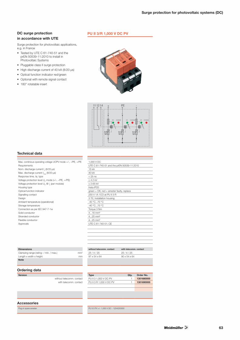
+141211 PE
U
�
U
�
OK CHANGE OK CHANGE
-
U
�
OK CHANGE
PU II 3/R 1,000 V DC PV
Technical data Max. continious operating voltage UCPV mode +/-, -/PE, +/PE
Requirements
Nom. discharge current In (8/20 μs)
Max. discharge current Imax (8/20 μs)
Response time, ta, type
Voltage protection level UP mode (+/-, -/PE, +/PE)
Voltage protection level UP @ In (per module)
Housing type
Optical function indicator
Signalling contact
Design
Ambient temperature (operational)
Storage temperature
Connection as per IEC 947-7-1w
Solid conductor
Stranded conductor
Flexible conductor
Approvals
Dimensions
Clamping range (rating- / min. / max.) mm2
Length x width x height mmNote
Ordering dataVersion
without telecomm. contact
with telecomm. contact
AccessoriesPlug-in spare arrester
1,000 V DC
UTE C 61-740-51 and the prEN 50539-11:2010
15 kA
40 kA
< 25 ns
≤ 4.2 kV
≤ 2.65 kV
Insta IP20
green = OK; red = arrester faulty, replace
250 V 1A 1CO at PU II 3 R
3 TE; Installation housing
-40 °C...70 °C
-40 °C...70 °C
Torque 3 Nm
4...16 mm²
4...25 mm²
4...25 mm²
UTE C 61-740-51; CE
without telecomm. contact with telecomm. contact
25 / 4 / 25 25 / 4 / 25
97 x 54 x 64 90 x 54 x 64
Type Qty. Order No.PU II 3 1,000 V DC PV 1 1301680000
PU II 3 R 1,000 V DC PV 1 1301690000
PU II 0 PV +/- 1,000 V DC - 1254250000
Surge protection for photovoltaic systems (DC)
DC surge protection in accordance with UTE
Surge protection for photovoltaic applications, e.g. in France
• Tested by UTE C 61-740-51 and the prEN 50539-11:2010 to install in Photovoltaic Systems
• Pluggable class II surge protection
• High discharge current of 40 kA (8/20 μs)
• Optical function indicator red/green
• Optional with remote signal contact
• 180° rotatable insert
63

Technical data Rated voltage (AC)
max. continuous voltage, Uc (AC)
Requirements class to IEC 61643-1
Lightning test voltage I imp (10/350 μs)
Charge, typical
Specific energy, per path
Short-circuit current extinction without back-up fuse
Short-circuit strength with max. back-up fuse
Response time
Fuse, max.
Protection level Up (typical)
Optical function indicator
Signalling contact
Tightening torque range
Discharge current, max. (8/20 μs)
Rated discharge current per path (8/20 μs)
Temporary overvoltage - UTOV
Design
Ambient temperature (operational)
Storage temperature
Approvals
Dimensions
Clamping range (rating- / min. / max.) mm2
Length x width x height mmNote
Ordering dataVersion
Accessories
Surge protection for photovoltaic systems (AC)
Class I + II lightning arrester
Combi-arrester
• Class I + II plug-in arrester for lightning protection equipotential bonding
• Suitable for lightning protection level III and IV
• High impuls current with 12.5 kA (10/350 μs)
• Low protection level from <1.3 kV, thus also can be used for Class II surge protection
• No decoupling to class II and III arresters necessary
• Follow current need not be taken into account
L1 L2
N
U U
OK CHANGE OK CHANGE
PEL3
U
OK CHANGE
14 1211
PU I 3+1/R 280V/12.5kATN-S, IT, TT systems
230 V
280 V
I+II (combination arrester)
12.5 kA
6 As
45 kJ/Ω
6 As
25 kAeff
L-N: ≤ 25 ns; N-PE: 100 μs
160 A gL /gG
< 1,300 V
green = OK; red = arrester faulty, replace
250 V 1 A 1CO at PU I R
2,5 Nm…3 Nm
50 kA
30 kA
335 V
4 unit widths; Installation housing
-40 … 70 °C
-40 … 70 °CCE
without telecomm. contact with telecomm. contact25 / 4 / 25 25 / 4 / 25
97 / 72 / 64 97 / 72 / 64
Type Qty. Order No.PU I 3+1 280 V/12,5 kA 1 8859080000
PU I 3+1 R 280 V/12,5 kA 1 8859090000
Additional rated voltages on request
Plug-in spare arrester PU I 0 280 V/12,5kA - 8859120000
64

Technical data Rated voltage (AC)
max. continuous voltage, Uc (AC)
Requirements class to IEC 61643-1
Lightning test voltage I imp (10/350 μs)
Charge, typical
Specific energy, per path
Short-circuit current extinction without back-up fuse
Short-circuit strength with max. back-up fuse
Response time
Fuse, max.
Protection level Up (typical)
Optical function indicator
Signalling contact
Tightening torque range
Discharge current, max. (8/20 μs)
Rated discharge current per path (8/20 μs)
Temporary overvoltage - UTOV
Design
Ambient temperature (operational)
Storage temperature
Approvals
Dimensions
Clamping range (rating- / min. / max.) mm2
Length x width x height mmNote
Ordering dataVersion
without telecomm. contact
with telecomm. contact
Accessories
Surge protection for photovoltaic systems (AC)
Class I + II lightning arrester
Combi-arrester
• Class I + II plug-in arrester for lightning protection equipotential bonding
• Suitable for lightning protection level III and IV
• High impulse current with 12.5 kA (10/350 μs)
• Low protection level from <1.3 kV, thus also can be used for Class II surge protection
• High-power varistor, non-blow-out arrester
• No decoupling to class II and III arresters necessary
• Follow current need not be taken into account
L1 L214 1211
PEN
U U
OK CHANGE OK CHANGE
L3
U
OK CHANGE
PU I 3/R 280 V/12.5 kATN-C system
230 V
280 V
I+II (combination arrester)
12.5 kA
6 As.
45 kJ/Ω
6 As.
25 kAeff
≤ 25 ns
160 A gL
< 1300 V
green = OK; red = arrester faulty, replace
250 V 1A 1CO at PU I 3 R
2.5 Nm…3 Nm
50 kA
30 kA
335 V
3 unit widths; Installation housing
-40 … 70 °C
-40 … 70 °C
CE
without telecomm. contact with telecomm. contact25 / 4 / 25 25 / 4 / 25
90 x 54 x 64 97 / 72 / 64
Type Qty. Order No.PU I 3 280 V/12,5 kA 1 8858990000
PU I 3 R 280 V/12,5 kA 1 8859010000
Additional rated voltages on request
Plug-in spare arrester PU I 0 280 V/12,5kA - 8859120000
L114 1211
N
U
OK CHANGE
PE
PU I 1+1/R 280 V/12.5 kASingle-phase system
230 V
280 V
I+II (combination arrester)
12.5 kA
6 As.
45 kJ/Ω
6 As.
25 kAeff
≤ 25 ns
160 A gl
1500 V
green = OK; red = arrester faulty, replace
250 V 1A 1CO at PK I 1R
2.5 Nm…3 Nm
50 kA
20 kA
335 V
2 unit widths; Installation housing
-40 … 70 °C
-40 … 70 °C
CW, ÖVE
without telecomm. contact with telecomm. contact25 / 4 / 25 25 / 4 / 25
90 x 36 x 64 97 / 72 / 64* This product also fulfils the requirements for Class III with Uoc: 6 kV
Type Qty. Order No.PU I 1+1/ 280 V/ 12,5 kA 1 8859100000
PU I 1+1/ R 280 V/ 12,5 kA 8859110000
Additional rated voltages on request
Plug-in spare arrester PU I 0 280 V/12,5kA - 8859120000
65
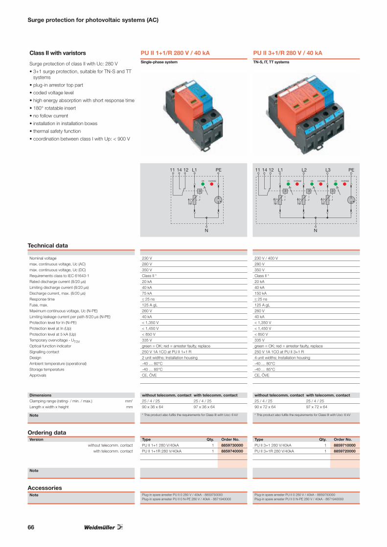
66
Surge protection for photovoltaic systems (AC)
Class II with varistors
Surge protection of class II with Uc: 280 V
• 3+1 surge protection, suitable for TN-S and TTsystems
• plug-in arrestor top part
• coded voltage level
• high energy absorption with short response time
• 180° rotatable insert
• no follow current
• installation in installation boxes
• thermal safety function
• coordination between class I with Up: < 900 V
Technical data
Nominal voltage
max. continuous voltage, Uc (AC)
max. continuous voltage, Uc (DC)
Requirements class to IEC 61643-1
Rated discharge current (8/20 μs)
Limiting discharge current (8/20 μs)
Discharge current, max. (8/20 μs)
Response time
Fuse, max.
Maximum continuous voltage, Uc (N-PE)
Limiting leakage current per path 8/20 μs (N-PE)
Protection level for In (N-PE)
Protection level at In (Up)
Protection level at 5 kA (Up)
Temporary overvoltage - UTOVOptical function indicator
Signalling contact
Design
Ambient temperature (operational)
Storage temperature
Approvals Rus in Vorbereitung
Dimensions
Clamping range (rating- / min. / max.) mm2
Length x width x height mm
Note
Ordering dataVersion
without telecomm. contact
with telecomm. contact
Note
AccessoriesNote
PU II 3+1/R 280 V / 40 kA
L1 L2
N
U U
OK CHANGE OK CHANGE
PEL3
U
OK CHANGE
14 1211
230 V / 400 V
280 V te Dauerspannung, Uc (AC)
350 V te Dauerspannung, Uc (DC)
Class II * klasse nach IEC 61643-1
20 kA leitstrom (8/20 μs)
40 kA ableitstrom (8/20 μs)
150 kA strom, max. (8/20 μs)
≤ 25 ns t
125 A gL ung, max.
260 V te Dauerspannung, Uc (N-PE)
40 kA ableitstrom je Pfad 8/20 μs (N-PE)
< 1,350 V gel bei In (N-PE)
< 1,450 V el bei In (Up)
< 850 V egel bei 5kA (Up)
335 V räre Überspannung - UTOVgreen = OK; red = arrester faulty, replace
250 V 1A 1CO at PU II 3+1 R
4 unit widths; Installation housing
-40 … 80°C peratur (Betrieb)
-40 … 85°C tur
CE, ÖVE
without telecomm. contact with telecomm. contact
25 / 4 / 25 25 / 4 / 25
90 x 72 x 64 97 x 72 x 64
* This product also fulfils the requirements for Class III with Uoc: 6 kV
Type Qty. Order No.
PU II 3+1 280 V/40kA 1 8859710000
PU II 3+1R 280 V/40kA 1 8859720000
Plug-in spare arrester PU II 0 280 V / 40kA - 8859750000Plug-in spare arrester PU II 0 N-PE 280 V / 40kA - 8871940000
PU II 1+1/R 280 V / 40 kA
L114 1211
N
U
OK CHANGE
PE
230 V / 400 V
280 V te Dauerspannung, Uc (AC)
350 V te Dauerspannung, Uc (DC)
Class II * klasse nach IEC 61643-1
20 kA leitstrom (8/20 μs)
40 kA ableitstrom (8/20 μs)
75 kA tstrom, max. (8/20 μs)
≤ 25 ns t
125 A gL ung, max.
260 V te Dauerspannung, Uc (N-PE)
40 kA ableitstrom je Pfad 8/20 μs (N-PE)
< 1,350 V gel bei In (N-PE),
< 1,450 V el bei In (Up)
< 850 V egel bei 5kA (Up)
335 V räre Überspannung - UTOVgreen = OK; red = arrester faulty, replace
250 V 1A 1CO at PU II 1+1 R
2 unit widths; Installation housing
-40 … 80°C peratur (Betrieb)
-40 … 85°C tur
CE, ÖVE
without telecomm. contact with telecomm. contact
25 / 4 / 25 25 / 4 / 25
90 x 36 x 64 97 x 36 x 64
* This product also fulfils the requirements for Class III with Uoc: 6 kV
Type Qty. Order No.
PU II 1+1 280 V/40kA 1 8859730000
PU II 1+1R 280 V/40kA 1 8859740000
Plug-in spare arrester PU II 0 280 V / 40kA - 8859750000Plug-in spare arrester PU II 0 N-PE 280 V / 40kA - 8871940000
Single-phase system TN-S, IT, TT systems

67
Surge protection for photovoltaic systems (AC)
Class II with varistors
Surge protection of class II
with Uc: 280 V
• plug-in arrestor top section
• coded voltage level
• high energy absorption with short response time
• 180° rotatable insert
• no follow current
• installation in installation boxes
• thermal safety function
• coordination between class I with Up: < 900 V
Technical data
Nominal voltage
max. continuous voltage, Uc (AC)
max. continuous voltage, Uc (DC)
Requirements class to IEC 61643-1
Rated discharge current (8/20 μs)
Limiting discharge current (8/20 μs)
Discharge current, max. (8/20 μs)
Response time
Fuse, max.
Protection level at In (Up)
Protection level at 5 kA (Up)
Temporary surge - UTOVOptical function indicator
Signalling contact
Design
Ambient temperature (operational)
Storage temperature
Approvals
Dimensions
Clamping range (rating- / min. / max.) mm2
Length x width x height mm
Note
Ordering dataVersion
without telecomm. contact
with telecomm. contact
Note
AccessoriesNote
PU II 3/R 280 V / 40 kA
L1 L214 1211
PEN
U U
OK CHANGE OK CHANGE
L3
U
OK CHANGE
Technische Daten
230 V / 400 V
280 V te Dauerspannung, Uc (AC)
350 V te Dauerspannung, Uc (DC)
Class II * klasse nach IEC 61643-1
20 kA leitstrom (8/20 μs)
40 kA ableitstrom (8/20 μs)
110 kA strom, max. (8/20 μs)
≤ 25 ns t
125 A gL ung, max.
< 1,450 V el bei In (Up)
< 850 V egel bei 5kA (Up)
335 V räre Überspannung - UTOVgreen = OK; red = arrester faulty, replace
250 V 1A 1CO at PU II 3 R
3 unit widths; Installation housing
-40 … 80°C peratur (Betrieb)
-40 … 85°C tur
CE, ÖVE
without telecomm. contact with telecomm. contact
25 / 4 / 25 25 / 4 / 25
90 x 54 x 64 97 x 54 x 64
* This product also fulfils the requirements for Class III with Uoc: 6 kV
Type Qty. Order No.
PU II 3 280 V/40kA 1 8859630000
PU II 3 R 280 V/40kA 1 8859650000
Plug-in spare arrester PU II 0 280 V / 40kA - 8859750000
TN-C system

Surge protection for photovoltaic systems (AC)
L1
N
PEPE
N
L1
NN
OK CHANGE
14 1211 L2
N
L2
N
L3
N
L3
N
OK CHANGE OK CHANGE
14 1211 14 1211
U
�
U
�
U
�
PU I 3+1 (R) LCF 280 V/30kATN-S- or TT system
Technical data Voltage, Un per path
Voltage, Uc per path
Temporary overvoltage TOV
Max. continuous voltage, UC (N-PE)
Lightning test current, Iimp. (10/350 µs): (N-PE)
Limiting discharge current, Imax. (8/20 µs) (N-PE)
Requirements category acc. to IEC 61643-1
Lightning test current, Iimp. (10/350 µs): L-N
Specific energy, per path
Short-circuit strength with max. back-up fuse
Short-circuit current extinction without back-up fuse (N-PE)
Nominal discharge current, In (8/20 µs)
Limiting discharge current, Imax. (8/20 µs)
Discharge current, IPE
Sparkover time, ta, type
Back-up fuse, max.
Protection level, Up
Protection level, Up: (N-PE)
Visual function display
Signal contact at R
Design
Colour
Temperature
Connection according to IEC 947-7-1
solid
stranded
Stripping length
Torque
Marking on the top side
Dimensions (L x W x H) mmNote
Ordering dataVersion
Without remote signalling contact
With remote signalling contact
Accessories
230 V AC
280 V AC
335 V
260 V AC
100 kA
100 kA
I + II
30 kA
225 kJ/Ohm
25 kAeff
100 A
40 kA
60 kA
≤ 1 µA
≤ 100 ns
315 A gL/gG
≤ 1.5 kV
≤ 1.5 kV
red / green
250 V 1 A
Insta IP20
black
-40 °C ... +70 °C
4 ... 16 mm²
4 ... 25 mm²
15 mm
Min 2 Nm … max 3 Nm
DEK 5 yellow (L-N) and DEK 5 white (N-PE)
90 x 144 x 64
Type Qty. Order No.PU I 3+1 LCF 280 V/30KA 1 1266640000
PU I 3+1R LCF 280 V/30KA 1 1266650000
• Class I + II arrester for lightning and overvoltage protection
• Suitable for protective level I, II,III and IV
• High impulse current with 30 kA (10/350 µs)
• High power varistor with gas discharge tube
• Mains follow current need not be taken into account
• Suitable for the area before the electrical meter
L1
N
PEPE
N N
L1
N
OK CHANGE
14 1211
U
�
PU I 1+1 (R) LCF 280 V/30kASingle-phase system
230 V AC
280 V AC
335 V
260 V AC
50 kA
80 kA
I + II
30 kA
225 kJ/Ohm
25 kAeff
100 A
40 kA
60 kA
≤ 1 µA
≤ 100 ns
315 A gL/gG
≤ 1.5 kV
≤ 1.5 kV
red / green
250 V 1 A
Insta IP20
black
-40 °C ... +70 °C
4 ... 16 mm²
4 ... 25 mm²
15 mm
Min 2 Nm … max 3 Nm
DEK 5 yellow (L/ PE-N) and DEK 5 white (N-PE)
90 x 72 x 64
Type Qty. Order No.PU I 1+1 LCF 280 V/30KA 1 1266670000
PU I 1+1R LCF 280 V/30KA 1 1266680000
68

Surge protection for photovoltaic systems (AC)
L1L1
PEN
OK CHANGE
141211 L2L2 L3L3
PEN PEN PEN PEN PEN
OK CHANGE OK CHANGE
141211 141211
U
�
U
�
U
�
PU I 3 (R) LCF 280 V/30kATN-C system
Technical data Voltage, Un per path
Voltage, Uc per path
TOV
Requirements category acc. to IEC 61643-1
Lightning test current, Iimp. (10/350 µs)
Specific energy, per path
Short-circuit strength with max. back-up fuse
Nominal discharge current, In (8/20 µs)
Discharge current, Imax. (8/20 µs)
Discharge current, IPE
Sparkover time, ta, type
Back-up fuse, max.
Protection level, Up
Visual function display
Signal contact at R
Design
Colour
Temperature
Connection according to IEC 947-7-1
solid
stranded
Stripping length
Torque
Marking on the top side
Dimensions (L x W x H) mm
Note
Ordering dataVersion
Without remote signalling contact
With remote signalling contact
Accessories
230 V AC
280 V AC
335 V
I + II
30 kA
225 kJ/Ohm
25 kAeff
40 kA
60 kA
≤ 1 µA
≤ 100 ns
315 A gL/gG
≤ 1.5 kV
red / green
250 V 1 A
Insta IP20
black
-40 °C ... +70 °C
4 ... 16 mm²
4 ... 25 mm²
15 mm
Min 2 Nm … max 3 Nm
DEK 5 yellow (L- PEN)
90 x 106 x 64
Type Qty. Order No.PU I 3 LCF 280 V/30KA 1 1266600000
PU I 3 R LCF 280 V/30KA 1 1266610000
• Class I + II arrester for lightning and surge protection
• Suitable for protective classes I, II,III and IV
• High discharge current with 30 kA (10/350 µs)
• High power varistor with gas discharge tube
• Mains follow current need not be taken into account
• Suitable for the area before the electrical meter
69

Surge protection for data and communication devices
Pluggable surge protection for instrumentation, control and automation circuits
The pluggable VARITECTOR SPC surge protection stands out due to highest protection characteristics in combination with compact design. The protection element of the module can be removed, measured or replaced during operation without affecting the impedance and without breaking the instrumentation circuit of the wiring. These characteristics make the product an ideal protection element for interfaces in I&C systems.
With the VARITECTOR SPC R modules, error detection and failure indication are effected via internal monitoring. A green LED indicates active protection. A red LED stands for failure. This information is forwarded to the V-Control evaluation module. From here it can be signalled, for instance, to a control unit. The V-TEST testing device, monitoring the function of VARITECTOR SPC, also facilitates the observance of service intervals. The testing method is in accordance with the IEC 62305 standard.
A VARITECTOR SPC module can be used instead of a modular terminal when removing the protection module without affecting the impedance. Four binary or 2 analogue signals only require 17.8 mm of space on the mounting rail. Easy latching onto the earthed rail also saves time during installation. Colour codes mark the different voltage levels of all VARITECTOR SPC modules thus facilitating service during operation. The EMC-SET that is available as accessory, offers additional comfort for the connection of shielded cables. All VARITECTOR products are in compliance with the “overstress mode” required by the valid IEC 61643-21:2008 standard.
Saving space in the control cabinet: 4 binary signals or 2 analogue signals at 17.8 mm
For applications according to the IEC 62305: high impulse currents of up to 20 kA (8/20 µm) are safely discharged to PE. Tested according to the IEC 61643-21:2008 standard for classes D1, C2 and C1.
In compliance with the norms
Surge protection for photovoltaic systems
Space saving
70

Status indicator and alarm function: Protective functions for external evaluation
Monitoring
Surge protection for photovoltaic systems
Colour coding: Easy identification of different voltage levels in the control cabinet.≤ 12 V = green 24 V = binary signal blue 24 V = analogue signal yellow 48 V = red 60 V = violetspecific function = white
Fast identification
The right protective circuit for all applications: Current loops and binary signals, as well as integrated modules and combinations of current loop and supply voltage, e.g. 24 V.
Great variety
71
For further information, please ask for our catalogue:
ElectronicsSurge protectionOrder number: 1271290000
Ele
ktro
nik
– Ü
ber
span
nu
ng
ssch
utz
Kat
alo
g 2
011
Elektronik ÜberspannungsschutzKatalog
Bestellnummer:1271280000/01/2011/SMMD
www.weidmueller.com4.4
2011
4.4KA
TA
LOG
ÄgyptenArgentinienAserbaidschanAustralienBahrainBelgienBosnien undHerzegowinaBrasilienBulgarienChileChinaCosta RicaDänemarkDeutschlandEcuadorEstlandFinnlandFrankreichGriechenlandGroßbritannienHongkong IndienIndonesienIranIrlandIslandIsraelItalienJapanJordanien
KanadaKasachstanKatarKolumbienKoreaKroatienKuwaitLettlandLibanonLitauenLuxemburgMalaysiaMaltaMazedonienMexikoMoldauNeuseelandNiederlandeNorwegenOmanÖsterreichPakistanPeruPhilippinenPolenPortugalRumänienRusslandSaudi-ArabienSchwedenSchweiz
SerbienSingapurSlowakeiSlowenienSpanienSüdafrikaTaiwanThailandTschechienTunesienTürkeiUkraineUngarnUruguayUsbekistanVenezuelaVereinigteArabischeEmirateVereinigteStaatenVietnamWeißrussland
Weidmüller ist weltweit führender Anbieter vonLösungen für die elektrische Verbindung, Übertragungund Wandlung von Energie, Signalen und Daten imindustriellen Umfeld.
Das Unternehmen mit Hauptsitz in Detmold/Ostwestfalenentwickelt, produziert und vertreibt weltweit Produkteder elektrischen Verbindungstechnik und der Elektronik.Über ein Netzwerk von Applikationsspezialisten bietetWeidmüller Engineering-Dienstleistungen an undentwickelt anwendungsspezifische Lösungen.
Das gesamte Produkt- und Leistungsspektrum sichertunseren Kunden und Weidmüller in gleicher Weisedauerhaft Wettbewerbs- und Wertvorteile.

72
Surge protection for photovoltaic systems
Pluggable surge protection for the instrumentation, control and automation technology
Weidmüller‘s VARITECTOR SPC pluggable surge protection is remarkable for its combination of extremely high protective functionality and compact dimensions. It is suited for use in measurement and control circuits. The size is made possible by the seletion of installation dimensions, with a width of 17.8 mm (1TE).
Two versions are available: • VSPC: a surge protector
with no monitoring function • VSPC R: a surge protector
with monitoring function
The base components are plugged in to form a direct earthing contact via the mounting rail. Thus you save time during the connection. The VARITECTOR SPC series is optimally designed for compact installation locations in process automation, industrial automation or building automation. The two-stage surge-protection base components are equipped with gas discharge tubes, suppressor diodes (TVS) and decoupling components. Individual protective components (such as gas-filled spark gaps, varistors and suppressor diodes) supplement this product line. IEC 62305 requires that a periodic inspection of surge protection products be conducted. The functionality of all VARITECTOR SPC modules can be tested using testing
equipment (such as the V-TEST) that is available separately. The VARITECTOR SPC R modules also feature an internal monitoring function. The green LED signals when the protection function is ready. The red LED signals an error. Up to ten modules can be wired together in series. The modules signaling an evaluative module (the VSPC CONTROL UNIT) in the event of an error. VARITECTOR SPC-series surge protection is available with rated voltages of 5 V, 12 V, 24 V, 48 V and 60 V. The product‘s voltage level is colour-coded on the pluggable arrester. An earthing contact is established by snapping onto an earthed TS35 rail. The TS35 must be earthed in order to ensure safe power discharging via the terminals of up to 20 kA (8/20 µs) and 2.5 kA (10/350 µs). The rail must be screwed onto the earthed mounting plate for reasons of EMC. In order to optimize the protective function, a PE-contact connection should be made over the VSPC module every 60 cm for equipotential bonding. The pluggable protective element can be pulled out during operations without interrupting the measurement circuit.
A testing instrument, available as a Weidmüller accessory, allows you to test the protective element in compliance with the IEC 62305-3 directive. The accessory also includes a simple mechanism for applying the wire shield.
VARITECTOR SPC
General technical data
Storage temperature -40 °C…+80 °C
Operating temperature -40 °C…+70 °C
Air humidity 5 %…96 % RH with no condensation
Material V0, IP20
Connection screw connection
screwdriver blade 0.6 x 3.5 DIN 5264 (for example, 0.6x3.5x200,
order no. 9010110000)
rated torque 0.5 Nm
max. torque 0.8 Nm
stripping length 7 mm
solid 0.5…4 mm²
flexible 0.5…2.5 mm²
wire-end ferrule with plastic collar 0.5...2.5 mm²
Remote signalling connection screw connection
screwdriver blade0.4 x 2.0 DIN 5264 (for example, SD
0.4x2.0x60, order no. 9037160000)
max. torque 0.2 Nm
stripping length 6...6.5 mm
solid 0,5...1.5 mm²
Dimensions
L / H / W 90 mm / 69 mm / 17.8 mm
length with remote signalling contact 98 mm
Accessories
V-Test Testing device for functional tests of the
pluggable VSPC, PU II and PU I surge
protection.

73
VARITECTOR SPC – Choice of device depending on the interface
Interface Pluggable arrestor Order No. Order No. Order No. Pluggable arrestor Order No. Order No. Order No.Arrestor Base Base floating ground (FG) with remote signal contact (R) Arrestor Base Base floating ground (FG)
0(4) … 20 mA VSPC 2CL 24Vdc 0.5A 8924470000 8924710000 8924270000 VSPC 2CL 24Vdc 0.5A R 8951480000 8951710000 89517200000 … 10 V VSPC 2CL 24Vdc 0.5A 8924470000 8924710000 8924270000 VSPC 2CL 24Vdc 0.5A R 8951480000 8951710000 8951720000ADVANT VSPC 2CL HF 5Vdc 8924430000 8924710000 8924270000 VSPC 2CL HF 5Vdc R 8951680000 8951710000 8951720000ARCNET (Plus) VSPC RS485 2ch 8924670000 8924710000 8924270000 VSPC RS485 2ch R 8951670000 8951710000 8951720000BITBUS VSPC 2CL HF 12Vdc 8924460000 8924710000 8924270000 VSPC 2CL 12Vdc 0,5A R 8951470000 8951710000 8951720000BLN (Building VSPC 2CL HF 12Vdc 8924460000 8924710000 8924270000 VSPC 2CL 12Vdc 0,5A R 8951470000 8951710000 8951720000Level Network)CAN-Bus VSPC 2CL HF 12Vdc 8924460000 8924710000 8924270000 VSPC 2CL HF 12Vdc R 8951690000 8951710000 8951720000C-BUS VSPC 2CL HF 12Vdc 8924460000 8924710000 8924270000 VSPC 2CL HF 12Vdc R 8951690000 8951710000 8951720000CC-LINK VSPC 2CL HF 12Vdc 8924460000 8924710000 8924270000 VSPC 2CL HF 12Vdc R 8951690000 8951710000 8951720000Data Highway VSPC 2CL HF 12Vdc 8924460000 8924710000 8924270000 VSPC 2CL HF 12Vdc R 8951690000 8951710000 8951720000(Plus), DH+Datex-P VSPC 2CL HF 12Vdc 8924460000 8924710000 8924270000 VSPC 2CL HF 12Vdc R 8951690000 8951710000 8951720000DeviceNet VSPC 2CL HF 12Vdc 8924460000 8924710000 8924270000 VSPC 2CL HF 12Vdc R 8951690000 8951710000 8951720000DIN Messbus VSPC 2CL HF 12Vdc 8924460000 8924710000 8924270000 VSPC 2CL HF 12Vdc R 8951690000 8951710000 8951720000E1 VSPC 2CL HF 5Vdc 8924430000 8924710000 8924270000 VSPC 2CL HF 5Vdc R 8951680000 8951710000 8951720000FIPIO/FIPWAY VSPC 2CL HF 5Vdc 8924430000 8924710000 8924270000 VSPC 2CL HF 5Vdc R 8951680000 8951710000 8951720000Genius I/O Bus VSPC 2CL 12Vdc 0.5A 8924440000 8924710000 8924270000 VSPC 2CL 12Vdc 0.5A R 8951470000 8951710000 8951720000IEC-BUS VSPC 2CL HF 5Vdc 8924430000 8924710000 8924270000 VSPC 2CL HF 5Vdc R 8951680000 8951710000 8951720000LRE Netzwerke VSPC 2CL HF 5Vdc 8924430000 8924710000 8924270000 VSPC 2CL HF 5Vdc R 8951680000 8951710000 8951720000LUXMATE-Bus VSPC 2CL HF 24Vdc 8924510000 8924710000 8924270000 VSPC 2CL HF 24Vdc R 8951700000 8951710000 8951720000MODBUS(-PLUS) VSPC 2CL HF 12Vdc 8924460000 8924710000 8924270000 VSPC 2CL HF 12Vdc R 8951690000 8951710000 8951720000MPI-Bus VSPC RS485 2ch 8924670000 8924710000 8924270000 8951710000 8951720000N1 LAN VSPC 2CL HF 5Vdc 8924430000 8924710000 8924270000 VSPC 2CL HF 5Vdc R 8951680000 8951710000 8951720000P-NET VSPC 2CL HF 12Vdc 8924460000 8924710000 8924270000 VSPC 2CL HF 12Vdc R 8951690000 8951710000 8951720000Procontic CS31 VSPC 2CL HF 12Vdc 8924460000 8924710000 8924270000 VSPC 2CL HF 12Vdc R 8951690000 8951710000 8951720000Procontic T200 VSPC 2CL HF 12Vdc 8924460000 8924710000 8924270000 VSPC 2CL HF 12Vdc R 8951690000 8951710000 8951720000Profibus DP (FMS) VSPC 2CL HF 5Vdc 8924430000 8924710000 8924270000 VSPC 2CL HF 5Vdc R 8951680000 8951710000 8951720000
VSPC 2CL HF 12Vdc 8924460000 8924710000 8924270000 VSPC 2CL HF 12Vdc R 8951690000 8951710000 8951720000Prozess-Bus, VSPC 2CL HF 12Vdc 8924460000 8924710000 8924270000 VSPC 2CL HF 12Vdc R 8951690000 8951710000 8951720000Panel-BusP-Bus PU III R 24Vdc 8860360000 PU III R 24Vdc 8860360000PSM-EG-RS422… VSPC 2CL HF 12Vdc 8924460000 8924710000 8924270000 VSPC 2CL HF 12Vdc R 8951690000 8951710000 8951720000PSM-EG-RS485… VSPC 2CL HF 12Vdc 8924460000 8924710000 8924270000 VSPC 2CL HF 12Vdc R 8951690000 8951710000 8951720000RACKBUS VSPC 2CL HF 5Vdc 8924430000 8924710000 8924270000 VSPC 2CL HF 5Vdc R 8951680000 8951710000 8951720000RS 422A, V.11, VSPC 2CL HF 12Vdc 8924460000 8924710000 8924270000 VSPC 2CL HF 12Vdc R 8951690000 8951710000 8951720000X.27, RS 423ARS 449 VSPC 2CL HF 12Vdc 8924460000 8924710000 8924270000 VSPC 2CL HF 12Vdc R 8951690000 8951710000 8951720000RS 485 VSPC RS485 2ch 8924670000 8924710000 8924270000 VSPC RS485 2ch R 8951670000 8951710000 8951720000RS-232-C/V.24 VSPC 2CL HF 12Vdc 8924460000 8924710000 8924270000 VSPC 2CL HF 12Vdc R 8951690000 8951710000 8951720000SDLC VSPC 2CL HF 12Vdc 8924460000 8924710000 8924270000 VSPC 2CL HF 12Vdc R 8951690000 8951710000 8951720000SINEC L1 VSPC 2CL HF 5Vdc 8924430000 8924710000 8924270000 VSPC 2CL HF 5Vdc R 8951680000 8951710000 8951720000SINEC L2 DP VSPC 2CL HF 5Vdc 8924430000 8924710000 8924270000 VSPC 2CL HF 5Vdc R 8951680000 8951710000 8951720000Profibus DP VSPC RS485 2ch 8924670000 8924710000 8924270000 VSPC RS485 2ch R 8951670000 8951710000 8951720000TTY, 0(4) - 20 mA VSPC 2CL 24Vdc 0.5A 8924470000 8924710000 8924270000 VSPC 2CL 24Vdc 0.5A R 8951480000 8951710000 8951720000V.35 VSPC 2CL HF 5Vdc 8924430000 8924710000 8924270000 VSPC 2CL HF 5Vdc R 8951680000 8951710000 8951720000X.21/X.24 VSPC 2CL HF 12Vdc 8924460000 8924710000 8924270000 VSPC 2CL HF 12Vdc R 8951690000 8951710000 8951720000X.25/X.31 VSPC 2CL HF 12Vdc 8924460000 8924710000 8924270000 VSPC 2CL HF 12Vdc R 8951690000 8951710000 8951720000
This tables contains recommendations for the choice of device. Our technical consultants will be glad to assist you with your individual requirements.
Surge protection for photovoltaic systems

74
Surge protection for photovoltaic systems
unprotected protected
Complete module, direct earthing
Complete module, direct earthing, with remote signaling
Complete module, indirect earthing
Complete module, indirect earthing, with remote signaling
unprotected protected
unprotected protected
unprotected protected
1
5
2
6
3 4
9 10
7
11
8
12
GND GND
TS
1
5
2
6
3 4
9 10
7
11
8
12
GND GND
TS
X2X1
FAULTOK
1
5
2
6
3 4
9 10
7
11
8
12
GND GND
TS
1
5
2
6
3 4
9 10
7
11
8
12
GND GND
TS
X2X1
FAULTOK
Technical datafor all VSPC 2CLDielectric strength with FG against PE > 500 V
Volume resistivity per path 2.2 Ω
Overstressed fault mode Mode 2
Requirement category acc. to IEC 61643-21 C1; C2; C3; D1
Surge strength C1 < 1 kA / 8/20 µs
Surge strength C2 5 kA / 8/20 µs
Surge strength C3 100 A / 10/1000 µs
Surge strength D1 2.5 kA / 10/350 µs
Rated discharge current IN (8/20 µs) wire-wire / wire-PE / GND-PE 2.5 kA / 2.5 kA / 2.5 kA
Rated discharge current Imax (8/20 µs) wire-wire / wire-PE / GND-PE 10 kA / 2 x 10 kA / 10kA
Lightning test current, Iimp. (10/350 µs) wire-wire / wire-PE / GND-PE 2.5 kA / 2.5 kA / 2.5 kA
Degree of protection IP20
Type of connection Pluggable in VSPC BASE
Storage temperature -40 °C…+80 °C
Ambient temperature (operational) -40 °C…+70 °C
Rel. humidity 5 %…96 % RH
Degree of protection IP20
Dimensions of complete module (arrester + base element) Without telecomm. contact With telecomm. contact (R)
Length x Width x Height mm 90 x 17.8 x 69 98 x 17.8 x 69Note
VSPC 2CL – Protection for two analogue signals
• Optional monitoring function with status indicator and signaling function
• Pluggable arrester (plug-in / disconnect interruption-free and impedance neutral)
• Testable with V-TEST instrument• Space-saving design for two analog signals with signaling
contact, without additional space requirements• Version with non-earthed PE connection for avoiding
potential differences• Usable in accordance with installations standard IEC 62305• Integrated PE contact in base element, safely discharges
up to 20 kA (8/20 µs) and 2.5 kA (10/350 µs) to PE
Ordering data for baseType Qty. Order No.Base element, direct earthing 1 8924710000
Base element, indirect earthing via spark gap (FG, floating ground) 1 8924270000
Base element, direct earthing with remote contact 1 8951710000
Base element, indirect earthing with remote signaling 1 8951720000
Note: The basis elements are to be ordered separately
Base elements / base to arresters

75
Surge protection for photovoltaic systems
VSPC 2CL – arrester / plug-in elements
Ordering data
Rated voltage (DC)
Max. continuous voltage, Uc (DC)Alternating-current strength
Rated current
Surge strength
Signaling contact
Optical function indicator (VSPC R)
Transmission test (-3dB)
Impulse reset
tested
Residual voltage Up
wire-wire / wire-PE / GND-PE
Protection level on output side sym.,
input 1 kV/µs, typ.
input 8/20 µs, typ.
Protection level on output side unsym.,
input 1 kV/µs, typ.
input 8/20 µs, typ.
Ordering data
Without signaling contact/function indicator Type
Order No.
With signaling contact/function indicator Type Order No.
Qty.Note
VSPC 2CL 5 V DC
5 V DC
6.4 V DC
450 mA
UN 250 V AC 0.1 A 1CO at VSPC R
with VSPC CONTROL UNIT
green = OK; red = arrester faulty, replace
730 KHz
≤ 20 ms
acc. to IEC61643-21
< 800 V
12 V / 450 V / 800 V
< 12 V
< 12 V
< 450 V
< 800 V
VSPC 2CL 5VDC 0.5A
8924400000
VSPC 2CL 5VDC 0.5A R8951460000
1 piece
VSPC 2CL 12 V DC
12 V DC
15 V DC
450 mA
UN 250 V AC 0.1 A 1CO at VSPC R
with VSPC CONTROL UNIT
green = OK; red = arrester faulty, replace
1.7 MHz
≤ 20 ms
acc. to IEC61643-21
< 800 V
25 V / 450 V / 800 V
< 25 V
< 25 V
< 450 V
< 800 V
VSPC 2CL 12VDC 0.5A
8924440000
VSPC 2CL 12VDC 0.5A R8951470000
1 piece
VSPC 2CL 24 V DC
24 V DC
28 V DC
450 mA
UN 250 V AC 0.1 A 1CO at VSPC R
with VSPC CONTROL UNIT
green = OK; red = arrester faulty, replace
2.3 MHz
30 ms
acc. to IEC61643-21
< 800 V
45 V / 450 V / 800 V
< 45 V
< 45 V
< 450 V
< 800 V
VSPC 2CL 24VDC 0.5A
8924470000
VSPC 2CL 24VDC 0.5A R8951480000
1 piece
Ordering data
Rated voltage (DC)
Max. continuous voltage, Uc (DC)Alternating-current strength
Rated current
Surge strength
Signaling contact
Optical function indicator (VSPC R)
Transmission test (-3dB)
Impulse reset
tested
Residual voltage Up
wire-wire / wire-PE / GND-PE
Protection level on output side sym.,
input 1 kV/µs, typ.
input 8/20 µs, typ.
Protection level on output side unsym.,
input 1 kV/µs, typ.
input 8/20 µs, typ.
Ordering data
Without signaling contact/function indicator Type
Order No.
With signaling contact/function indicator Type Order No.
Qty.Note
VSPC 2CL 24 V AC
24 V AC / 34 V DC
28 V AC / 39 V DC
450 mA
UN 250 V AC 0.1 A 1CO at VSPC R
with VSPC CONTROL UNIT
green = OK; red = arrester faulty, replace
2,7 MHz
≤ 450 ms
acc. to IEC61643-21
< 650 V
60 V / 450 V / 800 V
< 60 V
< 60 V
< 450 V
< 800 V
VSPC 2CL 24 V AC 0.5A
8924490000
VSPC 2CL 24VAC 0.5A R1093400000
1 piece
VSPC 2CL 48 V AC
48 V AC / 68 V DC
60 V AC / 85 V DC
350 mA
no
green = OK; red = arrester faulty, replace
4,8 MHz
≤ 500 ms
acc. to IEC61643-21
< 650 V
85 V / 450 V / 650 V
500 ms
< 85 V
< 85 V
< 450 V
< 650 V
VSPC 2CL 48 V AC 0.5A
8951490000
1 piece
VSPC 2CL 60 V AC
60 V AC / 85 V DC
72 V AC / 101 V DC
250 mA
no
green = OK; red = arrester faulty, replace
7,3 MHz
≤ 500 ms
acc. to IEC61643-21
< 650 V
100 V / 450 V / 650 V
500 ms
< 100 V
< 100 V
< 450 V
< 650 V
VSPC 2CL 60 V AC 0.5A
8951500000
1 piece

Surge protection for photovoltaic systems
unprotected protected
Complete module, direct earthing
Complete module, direct earthing, with remote signaling
Complete module, indirect earthing
Complete module, indirect earthing, with remote signaling
unprotected protected
unprotected protected
unprotected protected
1
5
2
6
3 4
9 10
7
11
8
12
GND GND
TS
1
5
2
6
3 4
9 10
7
11
8
12
GND GND
TS
X2X1
FAULTOK
1
5
2
6
3 4
9 10
7
11
8
12
GND GND
TS
1
5
2
6
3 4
9 10
7
11
8
12
GND GND
TS
X2X1
FAULTOK
Technical datafor all VSPC 2CL HFDielectric strength with FG against PE > 500 V
Rated current 450 mA
Volume resistivity per path 2.2 Ω
Overstressed fault mode Mode 2
Requirement category acc. to IEC 61643-21 C1; C2; C3; D1
Surge strength C1 < 1 kA / 8/20 µs
Surge strength C2 5 kA / 8/20 µs
Surge strength C3 100 A / 10/1,000 µs
Surge strength D1 2.5 kA 10/350 µs
Rated discharge current IN (8/20 µs) wire-wire / wire-PE / GND-PE 2.5 kA / 2.5 kA / 2.5 kA
Rated discharge current Imax (8/20 µs) wire-wire / wire-PE / GND-PE 10 kA / 2 x 10 kA / 10kA
Lightning test current, Iimp. (10/350 µs) wire-wire / wire-PE / GND-PE 2.5 kA / 2.5 kA / 2.5 kA
Degree of protection IP20
Type of connection Pluggable in VSPC BASE
Storage temperature -40 °C…+80 °C
Ambient temperature (operational) -40 °C…+70 °C
Rel. humidity 5 %…96 % RH
Degree of protection IP20
Dimensions of complete module (arrester + base element) Without telecomm. contact With telecomm. contact (R)
Length x Width x Height mm 90 x 17.8 x 69 98 x 17.8 x 69Note
VSPC 2CL HF – for high transmission rates without signal delays
• Optional monitoring function with status indicator and signaling function
• Pluggable arrester (plug-in / disconnect interruption-free and impedance neutral)
• Testable with V-TEST instrument• Space-saving design with optional signaling contact,
without additional space requirements• High transmission rates with low attenuation values• Usable in accordance with installations standard IEC 62305• Integrated PE contact in base element, safely discharges
up to 20 kA (8/20 µs) and 2.5 kA (10/350 µs) to PE
Ordering data for baseType Qty. Order No.Base element, direct earthing 1 8924710000
Base element, indirect earthing via spark gap (FG, floating ground) 1 8924270000
Base element, direct earthing with remote signaling 1 8951710000
Base element, indirect earthing with remote signaling 1 8951720000
Note: The basis elements are to be ordered separately
Base elements / base to arresters
76

Surge protection for photovoltaic systems
VSPC 2CL HF – arrester / plug-in elements
Ordering data
Rated voltage (DC)
Max. continuous voltage, Uc (DC)Alternating-current strength
Surge strength
Signaling contact
Optical function indicator (VSPC R)
Transmission test (-3dB)
Impulse reset
tested
Residual voltage Up
wire-wire / wire-PE / GND-PE
Protection level on output side sym.,
input 1 kV/µs, typ.
input 8/20 µs, typ.
Protection level on output side unsym.,
input 1 kV/µs, typ.
input 8/20 µs, typ.
Ordering data
Without signaling contact/function indicator Type
Order No.
With signaling contact/function indicator Type Order No.
Qty.Note
VSPC 2CL HF 5 V DC
5 V DC
6.4 V DC
UN 250 V AC 0.1 A 1CO at VSPC R
with VSPC CONTROL UNIT
green = OK; red = arrester faulty, replace
103 MHz
≤ 20 ms
acc. to IEC61643-21
< 800 V
12 V / 450 V / 800 V
< 12 V
< 12 V
< 450 V
< 800 V
VSPC 2CL HF 5 V DC
8924430000
VSPC 2CL HF 5 V DC R8951680000
1 piece
VSPC 2CL HF 12 V DC
12 V DC
15 V DC
UN 250 V AC 0.1 A 1CO at VSPC R
with VSPC CONTROL UNIT
green = OK; red = arrester faulty, replace
104 MHz
≤ 80 ms
acc. to IEC61643-21
< 800 V
25 V / 450 V / 800 V
< 25 V
< 25 V
< 450 V
< 800 V
VSPC 2CL HF 12 V DC
8924460000
VSPC 2CL HF 12 V DC R8951690000
1 piece
VSPC 2CL HF 24 V DC
24 V DC
28 V DC
UN 250 V AC 0.1 A 1CO at VSPC R
with VSPC CONTROL UNIT
green = OK; red = arrester faulty, replace
103 MHz
≤ 40 ms
acc. to IEC61643-21
< 800 V
45 V / 450 V / 800 V
< 45 V
< 45 V
< 450 V
< 800 V
VSPC 2CL HF 24 V DC
8924510000
VSPC 2CLHF 24 VD C R8951700000
1 piece
77

Surge protection for photovoltaic systems
VSPC RS485
For serial data transmission• Optional monitoring function with status indicator and
signaling function• Pluggable arrester (plug-in / disconnect interruption-free
and impedance neutral)• Low residual voltage• Protection for conducted serial data transmission – RS485• Testable with V-TEST instrument• Integrated PE contact in base element, safely discharges
up to 20 kA (8/20 µs) and 2.5 kA (10/350 µs) to PE
Technical datafor all VSPC RS485Dielectric strength with FG against PE > 500 V
Rated current 450 mA
Volume resistivity per path 2.2 Ω
Overstressed fault mode Mode 2
Requirement category acc. to IEC 61643-21 C1; C2; C3; D1
Surge strength C1 < 1 kA / 8/20 µs
Surge strength C2 5 kA / 8/20 µs
Surge strength C3 100 A / 10/1,000 µs
Surge strength D1 2.5 kA / 10/350 µs
Rated discharge current IN (8/20 µs) wire-wire / wire-PE / GND-PE 2.5 kA / 2.5 kA / 2.5 kA
Rated discharge current Imax (8/20 µs) wire-wire / wire-PE / GND-PE 10 kA / 2 x 10 kA / 10 kA
Lightning test current, Iimp. (10/350 µs) wire-wire / wire-PE / GND-PE 0.2 kA / 2 x 0.2 kA / 0.2 kA
Type of connection Pluggable in VSPC BASE
Storage temperature -40 °C…+80 °C
Ambient temperature (operational) -40 °C…+70 °C
Rel. humidity 5 %…96 % RH
Degree of protection IP20
Temperature [°C]
Cur
rent
[m
A]
0
0.05
0.1
0.15
0.2
0.25
0.3
0.35
0.4
0.45
0.5
0 10 20 30 40 50 60 70 80 90 100
Dimensions of complete module (arrester + base element) Without telecomm. contact With telecomm. contact (R)
Length x Width x Height mm 90 x 17.8 x 69 98 x 17.8 x 69Note
unprotected protected
Complete module, direct earthing
Complete module, direct earthing, with remote signaling
Complete module, indirect earthing
Complete module, indirect earthing, with remote signaling
unprotected protected
unprotected protected
unprotected protected
1
5
2
6
3 4
9 10
7
11
8
12
GND GND
TS
1
5
2
6
3 4
9 10
7
11
8
12
GND GND
TS
X2X1
FAULTOK
1
5
2
6
3 4
9 10
7
11
8
12
GND GND
TS
1
5
2
6
3 4
9 10
7
11
8
12
GND GND
TS
X2X1
FAULTOK
Ordering data for baseType Qty. Order No.Base element, direct earthing 1 8924710000
Base element, indirect earthing via spark gap (FG, floating ground) 1 8924270000
Base element, direct earthing with remote signaling 1 8951790000
Base element, indirect earthing with remote signaling 1 8951800000
Note: The basis elements are to be ordered separately
Base elements / base to arresters
78
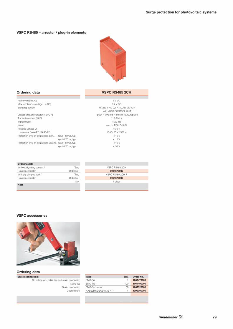
Surge protection for photovoltaic systems
Ordering dataShield connection:
Complete set - cable ties and shield connection
Cable ties
Shield connection
Cable tie tool
Type Qty. Order No.EMC-Set 1 1067470000
EMC-Tie 100 1067490000
EMC-Connector 50 1067520000
KABELBINDERZANGE RT-1 1 1296000000
VSPC accessories
VSPC RS485 2CH
5 V DC
6,4 V DC
UN 250 V AC 0,1 A 1CO at VSPC R
with VSPC CONTROL UNIT
green = OK; red = arrester faulty, replace
113.5 MHz
≤ 20 ms
acc. to IEC61643-21
≤ 35 V
15 V / 35 V / 500 V
< 10 V
< 15 V
< 10 V
< 35 V
VSPC RS485 2CH
8924670000
VSPC RS485 2CH R8951670000
1 piece
Ordering data
Rated voltage (DC)
Max. continuous voltage, Uc (DC)
Signaling contact
Optical function indicator (VSPC R)
Transmission test (-3dB)
Impulse reset
tested
Residual voltage Up
wire-wire / wire-PE / GND-PE
Protection level on output side sym., input 1 kV/µs, typ.
input 8/20 µs, typ.
Protection level on output side unsym., input 1 kV/µs, typ.
input 8/20 µs, typ.
Ordering data
Without signaling contact / Type
Function indicator Order No.
With signaling contact / TypeFunction indicator Order No.
Qty.Note
VSPC RS485 – arrester / plug-in elements
79

Surge protection for photovoltaic systems
Technical dataInputRated voltage (DC) 18 V…24 V DC…31 V DC
Rated current max. 50 mA
Power rating 1.5 W
OutputCurrent loop 8 mA bei < 51 V
Monitoring option 1…10 VSPC modules
Signal outputType 1 CO contact
Max. switching voltage / continuous current 250 V / 1 A
DiagnosticsOperating status Green LED
Defect at current loop Red LED (control unit and defective module)
Wire breakage Red/green LED, flashing
General dataTerminal rail TS35
Design, Degree of protection Insta-enclosure, IP20
Type of connection BL / SL
Storage temperature -40 °C…+80 °C
Ambient temperature (operational) -40 °C…+70 °C
Rel. humidity 5 %…96 % RH
Start-up time after fault correction 60 s
Dimensions
Dimensions incl. enclosure L x W x H mm 102 x 18 x 71.5Note
24 V
0 V
X2
X1
12
11
14VSPC CONTROL UNIT
X2 X2 X2X1 X1 X1
nmax = 10
VSPC...R
n = 2
VSPC...R
n = 1
VSPC...R
VSPC CONTROL UNIT 24 V DC
• For monitoring up to 10 VSPC surge protection modules• Signaling module for all VSPCs with status indicator• Signaling of cable breaks / signal interruptions• Voltage supply from 18...31 V DC• Potential-free changeover contact• Function indicator (red/green LED)
VSPC CONTROL UNIT 24 V DC
VSPC CONTROL UNIT 24 V DC
8972270000
1 piece
Ordering data
Type
Order No.
Qty.Note
Application
n x VSPC...RVSPC CONTROL UNIT
n ≤ 10
l ≤ 3 meter
Status indication
LED green LED red Function
OK
FAULT (one/several defect VSPC…R)
Wire break in monitoring current loop
80

81

V-TEST testing device
A testing device for pluggable surge protection: for testing in compliance with the IEC 62305-3 standard
The V-TEST is a compact and portable testing device intended for the pluggable VARITECTOR SPC (measurement and control) and the PU I/PU II (power supply) surge protection product lines. This testing device can be used to check the functionality of Weidmüller’s surge protection components in accordance with the test intervals stipulated in IEC 62305-3. It indicates the functional state of protective components.
The display shows the measured reading per component (GDT, MOV, TAZ) as „ok“ or „not ok“. This function allows you to detect ageing components by displaying possible damages right away. Thus total protection in guaranteed.
The V-TEST is equipped with a charger and a battery set which allows autonomous use in the field. A comfortable and protective carry bag is delivered free with the tester.
The compact device comes with an integrated rechargeable battery and protective case – making it perfect for use in the field.
Portable
The V-TEST self-calibrates when it is turned on, ensuring that it can always deliver precise measurement and test values.
Always delivering precise readings
It only takes a few simple menu steps (in German or English) to navigate directly to the measurement function.
Quick and easy to operate
Testing device for surge protection
82

PU I 3+1 280 V/12.5 kA
Combined lightning and overvoltage protection for lightning protection level III and IV, with the required 12.5 kA (10/350 µs). Eighty percent of all protective mechanisms (Class I/II) in power systems are covered.
VARITECTOR SPC
Pluggable surge protection for 2 analogue signals or 4 binary signals in measurement/control circuits – with integrated error detection and signaling functions in only 17.8 mm width.
The portable V-TEST can be used to carry out repeated testing in compliance with IEC 62305-3.
Maintaining the testing intervals
Testing device for surge protection
Lightningprotectionlevel(LPL)
Interval for completetesting
Interval for visual inspection
I 2 years 1 year
II 4 years 2 years
III/IV 6 years 3 years
83

Testing device for surge protection
VSPC, PU I and PU II accessories
V-TEST• Instrument for testing the protective functions of series:
PU I, PU II and VSPC• Device for realising standard IEC 62305 (periodic testing)• Handy device with integrated battery set for local
measurements• Result display via LCD display• Bilingual menu• Including protective bag and power supply• Intuitive user navigation in German and English
The V-TEST is a compact, portable instrument for theVaritector SPC pluggable surge protection (VSPC series) andsurge protection for power distribution (PU I and PU II series).With this instrument, the Weidmüller surge protection can betested for protective function in accordance with the requiredtest periods as stipulated by IEC62305. In a display, the measurement result is indicated with „ok“ or „not ok“ for each component.
Technical data
Rated voltage 100...240 V AC
Accumulator set 8 NiMH with 2600 mA
Storage temperature 0 °C ... 40 °C
Ambient temperature (operational) 0 °C ... 40 °C
Degree of protection IP20
Measuring range U < 1,000 V / I = 1 mA
UL94 flammability class V0
General tolerances of measurement rangeGas discharge tube +/- 10%
Varistor +/- 5%
TVS-diode +/- 5%
Note
V-TEST
230 x 122 x 65
V-TEST
8951860000
1
Ordering dataDimensionsLength x Width x Height mm
Ordering data
Type
Order No.
Qty.Note
84

85

Fuse solutions for PV strings
In order to achieve higher system voltages, single panels are connected in series during the installation of photovoltaic panels forming so-called “strings”. For this application Weidmüller offers terminals resisting a particular insulation test. This makes sure that the terminals permanently resist a voltage of 1,000 V DC under any climatic conditions.
Weidmüller provides fuse carriers for the proven cylindrical 10.3 mm x 38 mm (13/32“ x 1.5“) fuses that are suitable for mounting on DIN rails. They are compact, protected against accidental contact and in compliance with the requirements of the IEC.
Fuse Terminal Blocks
Fuse-holder terminals for cylindrical fuses up to 1,000 V DC
The W-series is the best choice for all applications requiring solid connections and safe contacts.
Long-proven screw connection technology
The pivoting release lever allows a quick, safe and reliable change of the fuse.
Convenient change of the fuse
86
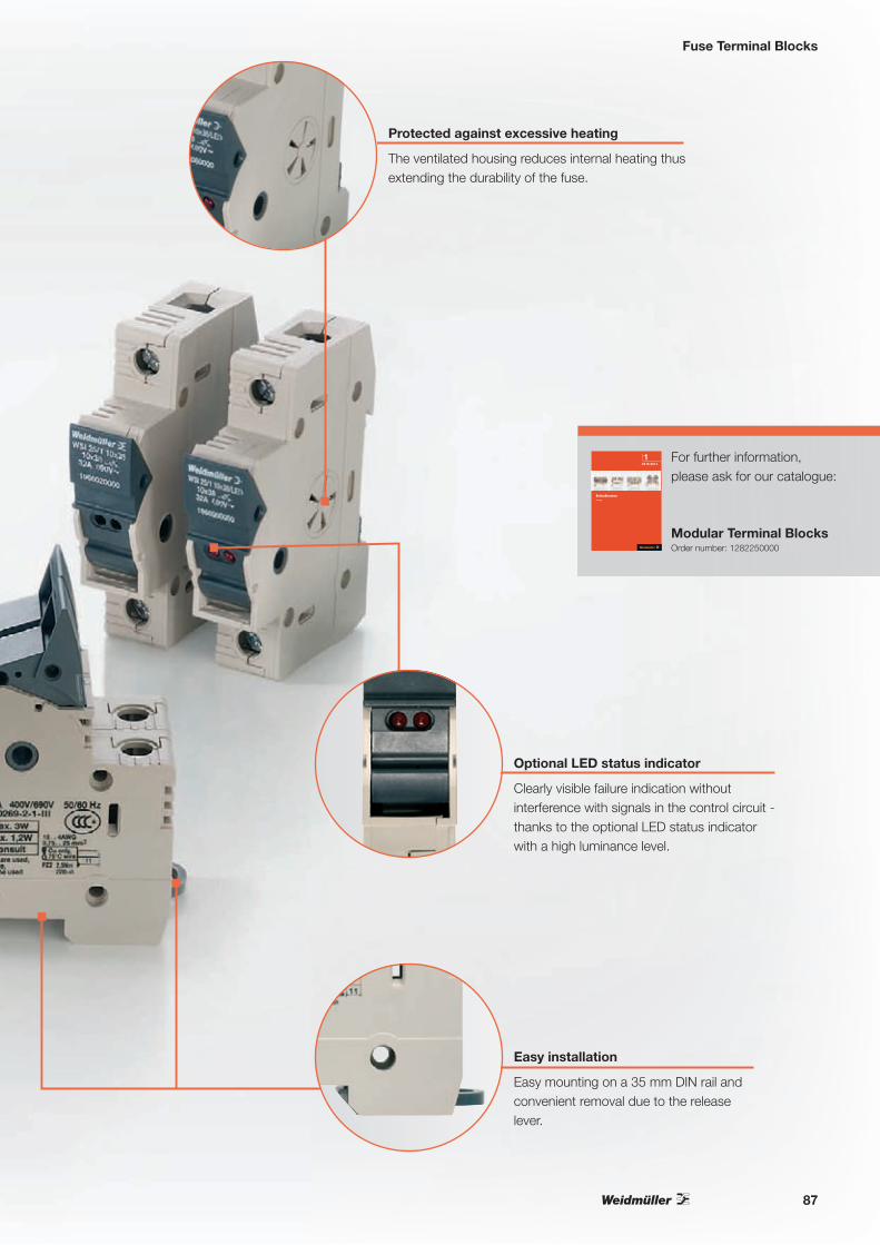
Fuse Terminal Blocks
Clearly visible failure indication without interference with signals in the control circuit - thanks to the optional LED status indicator with a high luminance level.
Optional LED status indicator
The ventilated housing reduces internal heating thus extending the durability of the fuse.
Protected against excessive heating
Easy mounting on a 35 mm DIN rail and convenient removal due to the release lever.
Easy installation
For further information, please ask for our catalogue:
Modular Terminal BlocksOrder number: 1282250000
1
Rei
hen
klem
men
Kat
alo
g 2
012/
2013
ReihenklemmenKatalog
2012 |2013
1KA
TA
LOG
Bestellnummer:1282240000/05/2011/SMMD
www.weidmueller.com
ÄgyptenArgentinienAserbaidschanAustralienBahrainBelgienBosnien undHerzegowinaBrasilienBulgarienChileChinaCosta RicaDänemarkDeutschlandEcuadorEstlandFinnlandFrankreichGriechenlandGroßbritannienHongkong IndienIndonesienIranIrlandIslandIsraelItalienJapanJordanien
KanadaKasachstanKatarKolumbienKoreaKroatienKuwaitLettlandLibanonLitauenLuxemburgMalaysiaMaltaMazedonienMexikoMoldauNeuseelandNiederlandeNorwegenOmanÖsterreichPakistanPeruPhilippinenPolenPortugalRumänienRusslandSaudi-ArabienSchwedenSchweiz
SerbienSingapurSlowakeiSlowenienSpanienSüdafrikaTaiwanThailandTschechienTunesienTürkeiUkraineUngarnUruguayUsbekistanVenezuelaVereinigteArabischeEmirateVereinigteStaatenVietnamWeißrussland
Weidmüller ist weltweit führender Anbieter vonLösungen für die elektrische Verbindung, Übertragungund Wandlung von Energie, Signalen und Daten imindustriellen Umfeld.
Das Unternehmen mit Hauptsitz in Detmold/Ostwestfalenentwickelt, produziert und vertreibt weltweit Produkteder elektrischen Verbindungstechnik und der Elektronik.Über ein Netzwerk von Applikationsspezialisten bietetWeidmüller Engineering-Dienstleistungen an undentwickelt anwendungsspezifische Lösungen.
Das gesamte Produkt- und Leistungsspektrum sichertunseren Kunden und Weidmüller in gleicher Weisedauerhaft Wettbewerbs- und Wertvorteile.
87

Fuse Terminal Blocks
Technical dataRated dataRated voltage, adjacent terminal VRated current ARated cross-section mm²Power loss 1 pole / 2 pole / 3 poleUL94 Flammability classAllowable power dissipation for standard version fuseAllowable power dissipation for semi-conductor protection version fuseOther technical dataFlexible / Flexible with wire end ferrule mm²Tightening torque range (clamping screw) Nm
Note
width x length x height with TS 35 x 7.5 mm
max. current / max. cond. cross-section A/mm2
max. clamping range mm2
1 pole without LED
1 pole with LED
Note
Note
Marking Systems
For fuses 10x38
WSI 25/1 10x38 1KV 25 mm²
18 x 58 x 8132 / 250.75 ... 25
Type Qty. Order No.
WSI 25/1 10x38 1KV 12 1137790000
WSI 25/1 10x38/LED 1KV 12 1137780000
Ordering data
IEC UL CSA EN 60079-71,000
3225 AWG 18 ... 4 AWG 18 ... 4
0.3 / 0.6 / 0.9V-03 W
4.3 W (10 mm2, 25 A)
0.75 … 25 / 0.75 … 252.0 ... 2.5
Accessories
Dimensions
Type Qty. Order No.
ESG 6/15 K MC WHITE 200 1880100000
Fuse Terminal Blocks
Especially for photovoltaic applications Weidmüller offers DIN rail mounted terminal blocks for the popular 10.3 mm x 38 mm (13/32” x 1.5”) midget fuses. Compact and touch safe, these terminals meet IEC requirements.
Features:• IEC certified for 1000 V DC, 32 A max.• 2, 3 pole realisable with the gaging kit• Mounting on 35 mm DIN rail• Only 18 mm wide per pole• Lever mechanism for quick and safe fuse
replacement• Vented housing to reduce internal heating and
extend fuse life• 3 W power dissipation maximum
88

Fuse Terminal Blocks
Safety fuses, 10 x 38 mm
Technical dataElectrical dataRated current A
Rated voltage V
Rated breaking capacity
Melting integral
Power output
Other data
Size mm
Test dropout voltage
Characteristics
Standard
Note
Ordering data
Note
2 4 6 8 10 12 16 20
1,000
30 kA @ DC 1,000 V (2 ms)
3 10 45 5 7 10 30 52
1.2 1.8 2.5 1.6 2 2.4 2.1 2.5
10 x 38
1,000 V DC
gPV/IEC (lf = 1.45 x ln)
IEC 60 269-6; As at 2009
UL 248-13
Order No.1224870000 1224880000 1224890000 1224900000 1224910000 1224920000 1224930000 1224950000
Qty.
10
In photovoltaic applications, fusing of individual strings is needed.
Specially designed fuses should be used as this deals with DC voltages and current. AC fuses are not suitable.
The range from 2 to 20 Amperes and up to 1,000 V DC can be covered with safety fuses, size 10 x 38 mm.
URZ 10 x 38 mm gPV DC 1,000 VVirtual fusing tim
e
Real value of the unaffected current
10 4
10 3
s
10 2
10 1
10 0
10 -1
10 -2
10-1
2
34568
10 0 101 10 2 10 3A2 3 4 5 6 8 2 3 4 5 6 8 2 3 4 5 6 8 2 3 4 5 6 8
2A
1A
4A
6A
10A
12A A61
/51 20
A
5A
3A
8A
1. 6A
E21526-30_2
89

Feed-through terminals
Terminal blocks for 1,000 V DC applications
Weidmüller offers solutions for the particular requirement of the DC area in a photovoltaic system
The photovoltaic market is booming and this has resulted in a demand for terminal blocks for use with 1,000 V DC. This is related to the fact that the performance of the system should be maximised, but with the minimum amount of current. This means that the voltage is raised.In the past, manufacturers of terminal blocks have concentrated on the clearance and creepage distances above all to determine the rating data. Weidmüller has changed its behaviour. According to our internal standards, we perform an AC partial discharge test on all terminal blocks. Now we do the same for DC voltages, which gives us a unique characteristic in the terminal block market.
All accessories, as well as all terminal blocks, can be easily marked at a high quality. In this way you can always have an overview of the system and it speeds up any measurements or troubleshooting.
Guaranteed easy marking
The extensive range of end brackets with different shapes and colours ensures more orientation and safety in your system.
Optical isolation and increasing the insulation distance
90

Feed-through terminals
For the DC area of a photovoltaic system, there are screw and tension-clamp terminals available for every need. Depending on the design, even be more connection techniques like Push-In or IDC can be used.
Free choice of connection technology
If terminal blocks are grouped into blocks of equal potential, there is a requirement that the voltage is isolated from the terminal to the mounting rail. Only at the transition from - to + does the terminal need to isolate the system voltage from the mounting rail and also from the neighbouring terminal (assuming no additional separation is used). Weidmüller presents a tailored solution for your particular application.
Potential blocks for string collection
The feed solutions from Weidmüller go in the opposite direction to the string collection. This means that there is a coordinated, comprehensive product range available which has been tested to 1,000 V DC.
Cross-sectional increase for the inverter feed
For further information, please ask for our catalogue:
Modular Terminal BlocksOrder number: 1282250000
1
Rei
hen
klem
men
Kat
alo
g 2
012/
2013
ReihenklemmenKatalog
2012 |2013
1KA
TA
LOG
Bestellnummer:1282240000/05/2011/SMMD
www.weidmueller.com
ÄgyptenArgentinienAserbaidschanAustralienBahrainBelgienBosnien undHerzegowinaBrasilienBulgarienChileChinaCosta RicaDänemarkDeutschlandEcuadorEstlandFinnlandFrankreichGriechenlandGroßbritannienHongkong IndienIndonesienIranIrlandIslandIsraelItalienJapanJordanien
KanadaKasachstanKatarKolumbienKoreaKroatienKuwaitLettlandLibanonLitauenLuxemburgMalaysiaMaltaMazedonienMexikoMoldauNeuseelandNiederlandeNorwegenOmanÖsterreichPakistanPeruPhilippinenPolenPortugalRumänienRusslandSaudi-ArabienSchwedenSchweiz
SerbienSingapurSlowakeiSlowenienSpanienSüdafrikaTaiwanThailandTschechienTunesienTürkeiUkraineUngarnUruguayUsbekistanVenezuelaVereinigteArabischeEmirateVereinigteStaatenVietnamWeißrussland
Weidmüller ist weltweit führender Anbieter vonLösungen für die elektrische Verbindung, Übertragungund Wandlung von Energie, Signalen und Daten imindustriellen Umfeld.
Das Unternehmen mit Hauptsitz in Detmold/Ostwestfalenentwickelt, produziert und vertreibt weltweit Produkteder elektrischen Verbindungstechnik und der Elektronik.Über ein Netzwerk von Applikationsspezialisten bietetWeidmüller Engineering-Dienstleistungen an undentwickelt anwendungsspezifische Lösungen.
Das gesamte Produkt- und Leistungsspektrum sichertunseren Kunden und Weidmüller in gleicher Weisedauerhaft Wettbewerbs- und Wertvorteile.
91

Feed-through terminals
Two connections
ZDU 6 6 mm²
8.1 x 65 x 45.657 / 100.22...10
IEC UL CSA EN 60079-7800 (AC)/1,000 (DC) 600 600 550
41 50 50 366 AWG 22...8 AWG 20...8 6
8 / 3A5 / V-0
? r u # i ~ a KEMA 97ATEX2521 URated connection0.5...10 0.5...10 / 0.5...613 / 1.0 x 5.5 mm
Twin wire-end ferrules ZH 0.5 - ZH 2.5 can be used.
IEC 60947-7-1 Ex e II T II 2 G D
Type Qty Order No.
ZDU 6 50 1608620000
ZDU 6 BL 50 1608630000
ZDU 6/3 AN 50 7907410000
ZDU 6/3 AN BL 50 7907420000For 3 connections: ZDU 6/3 AN, ZDU 6/3 AN BL
Type current Qty Order No.
ZQV 6/2 GE 41 A 60 1627850000
ZQV 6/3 GE 41 A 60 1627860000
ZQV 6/4 GE 41 A 60 1627870000
ZQV 6/24 GE 41 A 10 1908990000
Width
ZAP/TW 5 2 mm 50 1608830000
ZAP/TW 5 BL 2 mm 50 1608840000
ZEW 35 6 mm 20 9540000000
ZTA 3 ZDU6 8.1 mm 25 1654050000
SD 1.0x5.5x150 1 9008350000
ZAD 3/4 20 1609120000
DEK 5/8 / WS 12/6
Standard form
Technical data
Z-series standard ranges provide solutions for conductor cross-sections from 0.05 to 35 mm².
• for 1,000 V DC applications
Rated dataRated voltage VRated current ARated cross-section mm²Rated impulse voltage / Pollution severity kV/-Gauge to IEC 60947-1 / UL94 Flammability classApprovalsClamped conductors (H05V/H07V)solid / stranded mm²flexible / Stranded wire with end ferrules mm²Stripping length / Blade size mm/-
Note
Width/Length/height with TS35x7.5 mm
max. current / max. cond. cross-section A/mm²
Max. clamping range mm²
Version
Dark beige Wemid
Blue Wemid
Note
For detailed information of the further accessories and applications, please see our terminal catalogue
Pluggable cross-connection
2-pole
3-pole
4-pole
10-pole
20-/24-pole
End plate / partition
Dark beige Wemid
Blue Wemid
End bracket
Dark beige Wemid
Test adapter
Standard
With assembly peg
Screwdriver
Standard
Reducing sleeves
For conductors < 0,5 mm² / AWG 20
For conductors < 1,0 mm² / AWG 18
Cover
With lightning flash symbol
Ordering data
Marking systems
Marking tags
Zubehör
Two connections
ZDU 10 10 mm²
10.1 x 73.5 x 50.572 / 161.31...16
Cross-connection of ZDU 10 and ZDU 16 is possible using the ZQV 16-10. Cross-connection of ZDU 10 and ZDU 35 is possible using the ZQV 35-10.
Type Qty Order No.
ZDU 10 25 1746750000
ZDU 10 BL 25 1746760000
ZDU 10/3 AN 20 1767690000
ZDU 10/3 AN BL 20 1767700000For 3 connections: ZDU 10/3 AN, ZDU 10/3 AN BL
Type current Qty Order No.
ZQV 10/2 17.5 A 25 1739680000
Width
ZAP/TW ZDU10 2.7 mm 20 1748660000
ZAP/TW ZDU10 BL 2.7 mm 20 1764110000
ZEW 35 6 mm 20 9540000000
SD 1.0x5.5x150 1 9008350000
ZAD 4/5 20 1746730000
DEK 5/5 / WS 12/5
IEC UL CSA EN 60079-71,000 600 600 550
57 60 55 5010 AWG 16...6 AWG 16...6 10
8 / 3A6 / V-0
r # i ~ a KEMA 99ATEX5514 URated connection1.5...16 / 1.5...161.5...10 / 1.5...1018 / 1.0 x 5.5 mm
IEC 60947-7-1 Ex e II T II 2 G D
92
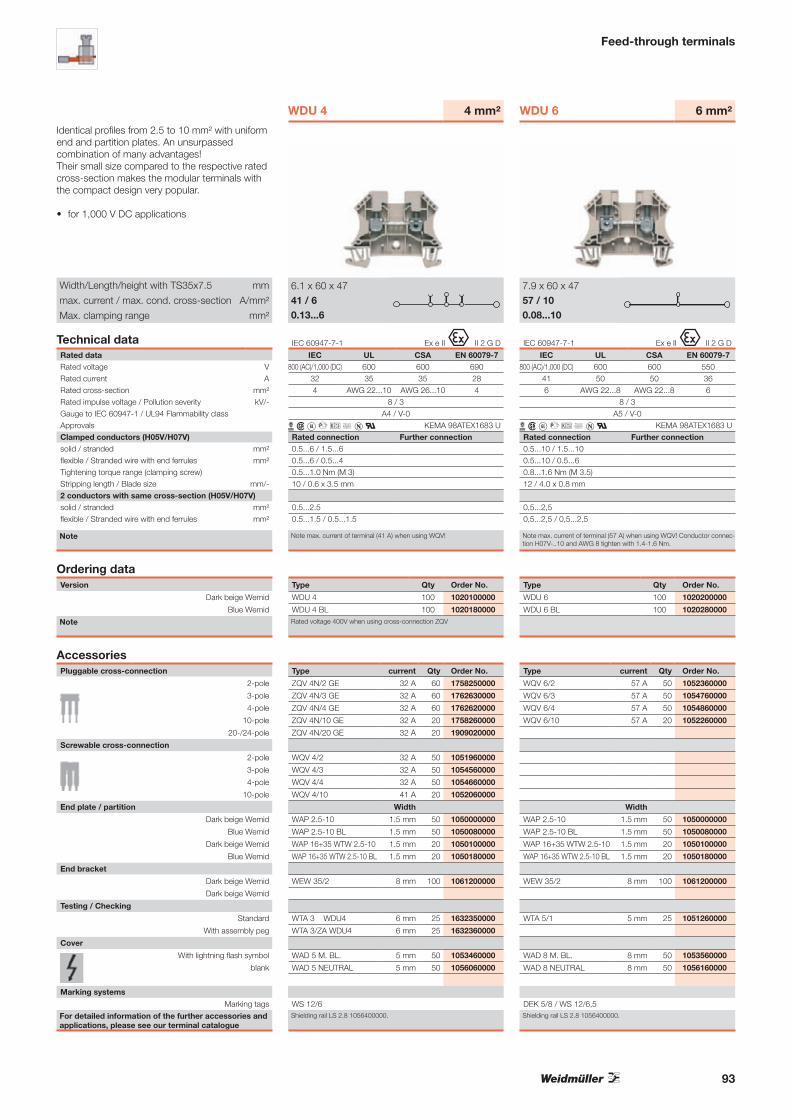
Feed-through terminals
Identical profiles from 2.5 to 10 mm² with uniform end and partition plates. An unsurpassed combination of many advantages!Their small size compared to the respective rated cross-section makes the modular terminals with the compact design very popular.
• for 1,000 V DC applications
WDU 6 6 mm²
7.9 x 60 x 4757 / 100.08...10
Note max. current of terminal (57 A) when using WQV! Conductor connec-tion H07V-..10 and AWG 8 tighten with 1.4-1.6 Nm.
Type Qty Order No.
WDU 6 100 1020200000
WDU 6 BL 100 1020280000
Shielding rail LS 2.8 1056400000.
Type current Qty Order No.
WQV 6/2 57 A 50 1052360000
WQV 6/3 57 A 50 1054760000
WQV 6/4 57 A 50 1054860000
WQV 6/10 57 A 20 1052260000
Width
WAP 2.5-10 1.5 mm 50 1050000000
WAP 2.5-10 BL 1.5 mm 50 1050080000
WAP 16+35 WTW 2.5-10 1.5 mm 20 1050100000
WAP 16+35 WTW 2.5-10 BL 1.5 mm 20 1050180000
WEW 35/2 8 mm 100 1061200000
WTA 5/1 5 mm 25 1051260000
WAD 8 M. BL. 8 mm 50 1053560000
WAD 8 NEUTRAL 8 mm 50 1056160000
DEK 5/8 / WS 12/6,5
IEC UL CSA EN 60079-7800 (AC)/1,000 (DC) 600 600 550
41 50 50 366 AWG 22...8 AWG 22...8 6
8 / 3A5 / V-0
? r u # i ~ x a KEMA 98ATEX1683 URated connection Further connection0.5...10 / 1.5...100.5...10 / 0.5...60.8...1.6 Nm (M 3.5)12 / 4.0 x 0.8 mm
0,5...2,5 0,5...2,5 / 0,5...2,5
IEC 60947-7-1 Ex e II T II 2 G D
WDU 4 4 mm²
6.1 x 60 x 4741 / 60.13...6
IEC UL CSA EN 60079-7800 (AC)/1,000 (DC) 600 600 690
32 35 35 284 AWG 22...10 AWG 26...10 4
8 / 3A4 / V-0
? r u # i ~ x a KEMA 98ATEX1683 URated connection Further connection0.5...6 / 1.5...60.5...6 / 0.5...40.5...1.0 Nm (M 3)10 / 0.6 x 3.5 mm
0.5...2.5 0.5...1.5 / 0.5...1.5
Note max. current of terminal (41 A) when using WQV!
IEC 60947-7-1 Ex e II T II 2 G D
Type Qty Order No.
WDU 4 100 1020100000
WDU 4 BL 100 1020180000Rated voltage 400V when using cross-connection ZQV
Shielding rail LS 2.8 1056400000.
Type current Qty Order No.
ZQV 4N/2 GE 32 A 60 1758250000
ZQV 4N/3 GE 32 A 60 1762630000
ZQV 4N/4 GE 32 A 60 1762620000
ZQV 4N/10 GE 32 A 20 1758260000
ZQV 4N/20 GE 32 A 20 1909020000
WQV 4/2 32 A 50 1051960000
WQV 4/3 32 A 50 1054560000
WQV 4/4 32 A 50 1054660000
WQV 4/10 41 A 20 1052060000
Width
WAP 2.5-10 1.5 mm 50 1050000000
WAP 2.5-10 BL 1.5 mm 50 1050080000
WAP 16+35 WTW 2.5-10 1.5 mm 20 1050100000
WAP 16+35 WTW 2.5-10 BL 1.5 mm 20 1050180000
WEW 35/2 8 mm 100 1061200000
WTA 3 WDU4 6 mm 25 1632350000
WTA 3/ZA WDU4 6 mm 25 1632360000
WAD 5 M. BL. 5 mm 50 1053460000
WAD 5 NEUTRAL 5 mm 50 1056060000
WS 12/6
Technical dataRated dataRated voltage VRated current ARated cross-section mm²Rated impulse voltage / Pollution severity kV/-Gauge to IEC 60947-1 / UL94 Flammability classApprovalsClamped conductors (H05V/H07V)solid / stranded mm²flexible / Stranded wire with end ferrules mm²Tightening torque range (clamping screw) Stripping length / Blade size mm/-2 conductors with same cross-section (H05V/H07V)solid / stranded mm²flexible / Stranded wire with end ferrules mm²
Note
Width/Length/height with TS35x7.5 mm
max. current / max. cond. cross-section A/mm²
Max. clamping range mm²
Version
Dark beige Wemid
Blue Wemid
Note
For detailed information of the further accessories and applications, please see our terminal catalogue
Pluggable cross-connection
2-pole
3-pole
4-pole
10-pole
20-/24-pole
Screwable cross-connection
2-pole
3-pole
4-pole
10-pole
End plate / partition
Dark beige Wemid
Blue Wemid
Dark beige Wemid
Blue Wemid
End bracket
Dark beige Wemid
Dark beige Wemid
Testing / Checking
Standard
With assembly peg
Cover
With lightning flash symbol
blank
Ordering data
Marking systems
Marking tags
Accessories
93

Identical profiles from 2.5 to 10 mm² with uniform end and partition plates. An unsurpassed combination of many advantages!Their small size compared to the respective rated cross-section makes the modular terminals with the compact design very popular.
• for 1,000 V DC applications
Breite/Länge/Höhe mit TS35x7,5 mm
max. Strom / max. Leiter A/mm²
max. Klemmbarkeitsbereich mm²
For detailed information of the further accessories and applications, please see our terminal catalogue
Screwable cross-connection
2-pole
3-pole
4-pole
10-pole
End plate / partition
Dark beige Wemid
Blue Wemid
Dark beige Wemid
Blue Wemid
End bracket
Dark beige Wemid
Testing / Checking
Standard
Cover
With lightning flash symbol
blank
Marking systems
Marking tags
Accessories
Feed-through terminals
WDU 10 10 mm²
9.9 x 60 x 4776 / 161.31...16
IEC UL CSA EN 60079-71,000 600 600 550
57 65 65 5010 AWG 18...6 AWG 16...6 10
8 / 3B6 / V-0
? r u # i ~ x a KEMA 98ATEX1683 URated connection Further connection1.5...16 / 1.5...161...6 / 1.5...161.2...2.4 Nm (M 4)12 / 1.0 x 5.5 mm
1...6 1...6 / 1...6
Note max. current of terminal (76 A) when using WQV! AWG 6/7 and H07V-R16 tightened with 2.4 Nm.
IEC 60947-7-1 Ex e II T II 2 G D
Type Qty Order No.
WDU 10 50 1020300000
WDU 10 BL 50 1020380000
Shielding rail LS 2.8 1056400000.
Type current Qty Order No.
WQV 10/2 57 A 50 1052560000
WQV 10/3 57 A 50 1054960000
WQV 10/4 57 A 50 1055060000
WQV 10/10 57 A 20 1052460000
Width
WAP 2.5-10 1.5 mm 50 1050000000
WAP 2.5-10 BL 1.5 mm 50 1050080000
WAP 16+35 WTW 2.5-10 1.5 mm 20 1050100000
WAP 16+35 WTW 2.5-10 BL 1.5 mm 20 1050180000
WEW 35/2 8 mm 100 1061200000
WTA 5/1 5 mm 25 1051260000
WAD 8 M. BL. 8 mm 50 1053560000
WAD 8 NEUTRAL 8 mm 50 1056160000
DEK 5/5 / WS 12/6,5
Technical dataRated dataRated voltage VRated current ARated cross-section mm²Rated impulse voltage / Pollution severity kV/-Gauge to IEC 60947-1 / UL94 Flammability classApprovalsClamped conductors (H05V/H07V)solid / stranded mm²flexible / Stranded wire with end ferrules mm²Tightening torque range (clamping screw) Stripping length / Blade size mm/-2 conductors with same cross-section (H05V/H07V)solid / stranded mm²flexible / Stranded wire with end ferrules mm²
Note
Width/Length/height with TS35x7.5 mm
max. current / max. cond. cross-section A/mm²
Max. clamping range mm²
Version
Dark beige Wemid
Blue Wemid
Note
Ordering data
With peg for higher connection stability
WDU 16 16 mm²
11.9 x 60 x 63101 / 251.5...25
IEC UL CSA EN 60079-71,000 600 600 690
76 85 85 6616 AWG 18...4 AWG 14...6 16
8 / 3B7 / V-0
? r u # i ~ x a KEMA 98ATEX1683 URated connection Further connection1.5...16 / 1.5...251.5...25 / 1.5...163.0...4.0 Nm (M 5)16 / 1.0 x 5.5 mm
1.5...6 1.5...6 / 1.5...6
Conductor connection H07V-..16 and AWG 6 with tightening torque of 2.0-2.4 Nm.
IEC 60947-7-1 Ex e II T II 2 G D
Type Qty Order No.
WDU 16/ZA 50 1028900000
WDU 16/ZA BL 50 1028980000Order No. 1020400000 and 1020480000 (blue) versions without pegs (50 pcs.)
Type current Qty Order No.
WQV 16/2 76 A 50 1053260000
WQV 16/3 76 A 50 1055160000
WQV 16/4 76 A 50 1055260000
WQV 16/10 76 A 10 1053360000
Width
WAP 16+35 WTW 2.5-10 1.5 mm 20 1050100000
WAP 16+35 WTW 2.5-10 BL 1.5 mm 20 1050180000
WEW 35/1 12 mm 50 1059000000
WAD 12 M. BL. 12 mm 50 1055960000
WAD 12 NEUTRAL 12 mm 50 1056260000
DEK 5/5 / WS 12/6,5
94

Feed-through terminals
Clamping screw / spigot for good connection stability
WDU 35 35 mm²
16 x 60 x 63150 / 502.5...50
The tightening torque is 4.5 Nm for 16 - 50 mm² and AWG 6 - 2/7 stranded conduc-tors. Copper straps can be used; possible connections: 3 to 9 layers 9 x 0.8 mm.
Type Qty Order No.
WDU 35/ZA 40 1028800000
WDU 35/ZA BL 40 1028880000Order No. 1020500000 and 1020580000 (blue) versions without pegs (40 pcs.)
Type current Qty Order No.
WQV 35/2 135 A 50 1053060000
WQV 35/3 112 A 50 1055360000
WQV 35/4 112 A 50 1055460000
WQV 35/10 112 A 10 1053160000
Width
WAP 16+35 WTW 2.5-10 1.5 mm 20 1050100000
WAP 16+35 WTW 2.5-10 BL 1.5 mm 20 1050180000
WEW 35/1 12 mm 50 1059000000
WAD 12 M. BL. 12 mm 50 1055960000
WAD 12 NEUTRAL 12 mm 50 1056260000
DEK 5/5 / WS 12/6,5
IEC UL CSA EN 60079-71,000 1,000 600 690125 150 120 10935 AWG 12...1 AWG 12...2 35
8 / 3B8 / V-0
? r u # i ~ x a KEMA 98ATEX1683 URated connection Further connection2.5...16 / 2.5...502.5...35 / 2.5...354.0...5.0 Nm (M 6)18 / 6.5 x 1.2 mm
2.5...10 / 16...162.5...16 / 2.5...16
IEC 60947-7-1 Ex e II T II 2 G D
Hexagonal socket / spigot for good connection stability
WDU 35 IK 35 mm²
16 x 60 x 63150 / 502.5...50
IEC UL CSA EN 60079-71,000 1,000 600 690125 150 120 10935 AWG 12...1 AWG 12...2 35
8 / 3B8 / V-0
? r u # i ~ x KEMA 98ATEX1683 URated connection Further connection2.5...16 / 2.5...502.5...35 / 2.5...354.0...6.0 Nm (M 6)18 / S6 (DIN 6911)
2.5...10 / 16...162.5...16 / 2.5...16
The tightening torque is 4.5 Nm for 16 - 50 mm² and AWG 6 - 2/7 stranded conduc-tors. Copper straps can be used; possible connections: 3 to 9 layers 9 x 0.8 mm.
IEC 60947-7-1 Ex e II T II 2 G D
Type Qty Order No.
WDU 35/IK/ZA 25 1029000000
Order No. 1020600000 and 1020680000 (blue) versions without pegs (25 pcs.)
Type current Qty Order No.
WQV 35/2 135 A 50 1053060000
WQV 35/3 112 A 50 1055360000
WQV 35/4 112 A 50 1055460000
WQV 35/10 112 A 10 1053160000
Width
WAP 16+35 WTW 2.5-10 1.5 mm 20 1050100000
WAP 16+35 WTW 2.5-10 BL 1.5 mm 20 1050180000
WEW 35/1 12 mm 50 1059000000
WAD 12 M. BL. 12 mm 50 1055960000
WAD 12 NEUTRAL 12 mm 50 1056260000
WS 12/6,5 / DEK 5/5
95

Identical profiles from 2.5 to 10 mm² with uniform end and partition plates. An unsurpassed combination of many advantages!Their small size compared to the respective rated cross-section makes the modular terminals with the compact design very popular.
• for 1,000 V DC applications• for 500 V DC applications WDU 35N
For detailed information of the further accessories and applications, please see our terminal catalogue
Marking systems
Marking tags
Feed-through terminals
Breite/Länge/Höhe mit TS35x7,5 mm
max. Strom / max. Leiter A/mm²
max. Klemmbarkeitsbereich mm²
Screwable cross-connection
2-pole
3-pole
4-pole
10-pole
End plate / partition
Dark beige Wemid
Blue Wemid
Dark beige Wemid
Blue Wemid
End bracket
Dark beige Wemid
Testing / Checking
Standard
Cover
With lightning flash symbol
blank
Accessories
Technical dataRated dataRated voltage VRated current ARated cross-section mm²Rated impulse voltage / Pollution severity kV/-Gauge to IEC 60947-1 / UL94 Flammability classApprovalsClamped conductors (H05V/H07V)solid / stranded mm²flexible / Stranded wire with end ferrules mm²Tightening torque range (clamping screw) Stripping length / Blade size mm/-2 conductors with same cross-section (H05V/H07V)solid / stranded mm²flexible / Stranded wire with end ferrules mm²
Note
Width/Length/height with TS35x7.5 mm
max. current / max. cond. cross-section A/mm²
Max. clamping range mm²
Version
Dark beige Wemid
Blue Wemid
Note
Ordering data
Suitable for power distribution Compact design
WDU 35N 35 mm²
16 x 66 x 51150 / 502.5...50
IEC UL CSA500 300 300125 150 1035 AWG 12...1 AWG 12...2
6 / 3B8 / V-0
r # a
Rated connection Further connection2.5...16 / 2.5...502.5...35 / 2.5...354.0...5.0 Nm (M 6)18 / 6.5 x 1.2 mm
2.5...6 2.5...6 / 2.5...6
The tightening torque is 4.5 Nm for 16 - 50 mm² and AWG 6 - 2/7 stranded conduc-tors. Copper straps can be used; possible connections: 3 to 9 layers 9 x 0.8 mm.
IEC 60947-7-1
Type Qty Order No.
WDU 35N 20 1040400000
WDU 35N BL 20 1040480000
Type current Qty Order No.
WQV 35N/2 135 A 20 1079200000
WQV 35N/3 101 A 20 1079300000
WQV 35N/4 101 A 20 1079400000
Width
WTW EN 3 mm 20 1058800000
WEW 35/2 8 mm 100 1061200000
WAD 16N GE BED 16 mm 50 1083600000
WAD 16N WS 16 mm 50 1083500000
DEK 5/5 / WS 12/6,5
Compact design
WDU 50N 50 mm²
18.5 x 70 x 70192 / 7010...70
IEC UL CSA EN 60079-71,000 600 600 690150 150 150 12650 AWG 10...1/0 AWG 8...1/0 50
8 / 3B10 / V-0
r u # a KEMA 98ATEX1685 URated connection Further connection10...16 / 10...7010...50 / 10...503.5...6.0 Nm (M 6)24 / S4 (DIN 6911)
/ 6...166...16 / 6...16
Copper straps can be used, possible connections: see online catalogue.
IEC 60947-7-1 Ex e II T II 2 G D
Type Qty Order No.
WDU 50N 10 1820840000
WDU 50N BL 10 1820850000
Auxiliary connection for the additional conductor „WZAD 50N“, order no. 1872720000 (up to 10 mm², 41 A)
Type current Qty Order No.
WQV 50N/2 150 A 5 1834060000
WQV 50N/3 150 A 5 1834070000
WQV 50N/4 150 A 5 1834080000
Width
WEW 35/1 12 mm 50 1059000000
WAD 20 GE WSD 20.5 mm 10 9512260000
WAD 20 WS 20.5 mm 10 9512270000
DEK 5/5 / WS 12/6,5
96

Feed-through terminals
Compact design
WDU 70N 70 mm²
20.5 x 75 x 86232 / 9510...95
IEC UL CSA EN 60079-71,000 600 600 690192 175 205 16770 AWG 6...3/0 AWG 8...2/0 70
8 / 3B11 / V-0
r { u # KEMA 98ATEX1683 URated connection Further connection10...16 / 10...9510...70 / 10...706.0...10 Nm (M 8)22 / S6 (DIN 6911)
6...16 / 10...10...25 / 6...25
Copper straps can be used, possible connections: see online catalogue.
IEC 60947-7-1 Ex e II T II 2 G D
Type Qty Order No.
WDU 70N/35 10 9512190000
WDU 70N/35 BL 10 9512420000
Auxiliary connection for the additional conductor „WZAD 70N“, order no. 1964830000 (up to 10 mm², 41 A)
Type current Qty Order No.
WQV 70N/2 192 A 5 9512240000
WQV 70N/3 192 A 5 9512250000
WQV 70N/4 192 A 5 9531290000
Width
WEW 35/1 12 mm 50 1059000000
WAD 20 GE WSD 20.5 mm 10 9512260000
WAD 20 WS 20.5 mm 10 9512270000
DEK 5/5 / WS 12/6,5
Compact design
WDU 95N/120N 120 mm²
27 x 91 x 90290 / 15016...150
Copper band strips can be used, refer to online catalogue When connecting the AWG conductor kcmil 250, the stripping length is 30 mm and the tightening torque is 16 Nm
Type Qty Order No.
WDU 95N/120N 5 1820550000
WDU 95N/120N BL 5 1820560000
Auxiliary connection for the additional conductor „WZAD 95N/120N“, order no. 1859580000 (up to 10 mm², 41 A)
Type current Qty Order No.
WQV 95N/120N-2 269 A 5 1826890000
WQV 95N/120N-3 269 A 5 1826900000
WQV 95N/120N-4 269 A 5 1826910000
Width
WEW 35/1 12 mm 50 1059000000
WAD 20 GE WSD 20.5 mm 10 9512260000
WAD 20 WS 20.5 mm 10 9512270000
DEK 5/5 / WS 12/6,5
IEC UL CSA EN 60079-71,000 1,000 1,000 880269 228 220 243120 AWG 4...kcmil 250 AWG 4...4/0 120
8 / 3B13 / V-0
r u # a KEMA 98ATEX1683 URated connection Further connection16...16 / 16...15016...120 / 16...9512...20 Nm (M 10)27 / S6 (DIN 6911)
10...16 / 10...3516...35 / 10...35
IEC 60947-7-1 Ex e II T II 2 G D
WDU 240 240 mm²
36 x 100 x 131.5415 / 24070...240
IEC UL CSA EN 60079-71,000 600 600 1,100415 380 380 300240 AWG 00...500 MCMAWG 00...500 MCM 240
8 / 3B15 / V-0
r # a KEMA 01ATEX2186 URated connection Further connection/ 70...24070...240 / 70...18512...20 Nm (M 10)40 / S8 (DIN 6911)
/ 35...9550...95 / 35...50
Copper straps can be used, possible connections: see online catalogue.
IEC 60947-7-1 Ex e II T II 2 G D
Type Qty Order No.
WDU 240 2 1802780000
WDU 240 BL 2 1822210000
Auxiliary connection for the additional conductor „WZAD 240“, order no. 180281000 (up to 10 mm², 57 A) ELPF insertion profile, for ribbon cable, order no. 1824680000
Type current Qty Order No.
WQB 240/2 320 A 5 1802790000
WQB 240/3 320 A 5 1802800000
Width
WEW 35/1 12 mm 50 1059000000
DEK 5/5 / WS 12/6,5
97

Modular PE terminals
Standard model
In hazardous area applications, the installation instructions
and the rated data specifications for accessories given in the
technical appendix must be followed.
Technical data
Z-series standard ranges provide solutions for conductor cross-sections from 0.05 to 35 mm².
Rated dataRated cross-section mm²Rated voltage to adjacent terminal VRated impulse withstand voltage to adjacent terminal kVPollution severityGauge to IEC 60947-1 / UL94 Flammability classApprovalsClamped conductors (H05V/H07V)solid / stranded mm²flexible / Stranded wire with end ferrules mm²Stripping length / Blade size mm/-
Note
Width/Length/height with TS35x7.5 mm
max. current / max. cond. cross-section A/mm²
Max. clamping range mm²
Version
green/yellow Wemid
Note
For detailed information of the further accessories and applications, please see our terminal catalogue
End plate / partition
Dark beige Wemid
End bracket
Dark beige Wemid
Test adapter
Standard
With assembly peg
Screwdriver
Standard
Reducing sleeves
For conductors < 0,5 mm² / AWG 20
For conductors < 1,0 mm² / AWG 18
Two connections
ZPE 6 6 mm²
8.1 x 65 x 45.5 / 100.22...10 PE
Type Qty Order No.
ZPE 6 50 1608670000
Type Width Qty Order No.
ZAP/TW 5 2 mm 50 1608830000
ZEW 35 6 mm 20 9540000000
ZTA 3 ZDU6 8.1 mm 25 1654050000
SD 1.0x5.5x150 1 9008350000
Ordering data
DEK 5/8 / WS 12/6
Marking systems
Marking tags
IEC UL CSA EN 60079-76 AWG 22...8 AWG 20...8 6
8008
3A5 / V-0
? r u # i ~ a KEMA 97ATEX2521 URated connection0.5...10 / 1.5...100.5...10 / 0.5...613 / 0.6 x 3.5 mm
Accessories
IEC 60947-7-2 Ex e II T II 2 G D
Three connections
ZPE 6/3 AN 6 mm²
8.1 x 90 x 45.6 / 100.22...10 PE
IEC UL CSA EN 60079-76 AWG 22...8 AWG 20...8 6
8008
3A5 / V-0
r # i ~ a KEMA 00ATEX2107 URated connection0.5...10 / 1.5...100.5...10 / 0.5...613 / 0.6 x 3.5 mm
IEC 60947-7-2 Ex e II T II 2 G D
Type Qty Order No.
ZPE 6/3AN 50 7907400000
Type Width Qty Order No.
ZAP/TW6/3AN 2 mm 20 7907370000
ZEW 35 6 mm 20 9540000000
ZTA 3 ZDU6 8.1 mm 25 1654050000
SD 1.0x5.5x150 1 9008350000
DEK 5/8 / WS 12/6
98

Modular PE terminals
Two connections
ZPE 10 10 mm²
10.1 x 73.5 x 50.5 / 161.31...16 PE
IEC UL CSA EN 60079-710 AWG 16...6 AWG 16...6 10
8008
3A6 / V-0
r { # i ~ a KEMA 99ATEX5514 URated connection1.5...16 / 10...161.5...10 / 1.5...1018 / 1.0 x 5.5 mm
IEC 60947-7-2 Ex e II T II 2 G D
Type Qty Order No.
ZPE 10 25 1746770000
Type Width Qty Order No.
ZAP/TW ZDU10 2.7 mm 20 1748660000
ZEW 35 6 mm 20 9540000000
SD 1.0x5.5x150 1 9008350000
DEK 5/5 / WS 12/6
Three connections
ZPE 10/3 AN 10 mm²
10.1 x 99 x 50.5 / 161.31...16 PE
IEC UL CSA EN 60079-710 AWG 16...6 AWG 16...6 10
8008
3A6 / V-0
r # i a KEMA 00ATEX2107 URated connection1.5...16 / 10...161.5...10 / 1.5...1018 / 1.0 x 5.5 mm
IEC 60947-7-2 Ex e II T II 2 G D
Type Qty Order No.
ZPE 10/3AN 20 1767670000
Type Width Qty Order No.
ZAP/TW 10/16 3 mm 20 1749580000
ZEW 35 6 mm 20 9540000000
SD 1.0x5.5x150 1 9008350000
DEK 5/5 / WS 12/6
99

For detailed information of the further accessories and applications, please see our terminal catalogue
Marking systems
Marking tags
Modular PE terminals
In hazardous area applications, the installation instructions
and the rated data specifications for accessories given in the
technical appendix must be followed.
Technical data
Identical profiles from 2.5 to 10 mm² with uniform end and partition plates. An unsurpassed combination of many advantages!Their small size compared to the respective rated cross-section makes the modular terminals with the compact design very popular.
Rated dataRated cross-section mm²Rated voltage to adjacent terminal VRated impulse withstand voltage to adjacent terminal kVShort-time withstand currentPollution severityGauge to IEC 60947-1 / UL94 Flammability classApprovalsClamped conductors (H05V/H07V)solid / stranded mm²flexible / Stranded wire with end ferrules mm²Tightening torque range (clamping screw) Tightening torque range (fixing screw) Stripping length / Blade size mm/-
Note
Width/Length/height with TS35x7.5 mm
max. cond. cross-section mm²
Max. clamping range mm²
Version
green/yellow Wemid
Note
End plate / partition
Dark beige Wemid
End bracket
Dark beige Wemid
Dark beige Wemid
Screwdriver
Standard
WPE 4 4 mm²
6.1 x 56 x 4760.13...6 PE
Type Qty Order No.
WPE 4 100 1010100000
Rail support for insulated installation of terminal rail „SH 2“ order no. 0494920000 (10 pcs)
Type Width Qty Order No.
WEW 35/2 8 mm 100 1061200000
SD 0.6x3.5x100 1 9008330000
Ordering data
DEK 5/6 / WS 12/6
IEC UL CSA EN 60079-74 AWG 22...10 AWG 26...10 4
8008
480 A (4 mm²)3
A4 / V-0
? r u # i ~ x a
Rated connection Further connection0.5...6 / 0.5...60.5...6 / 0.5...40.5...1.0 Nm (M 3)0.5...0.8 Nm 10 / 0.6 x 3.5 mm
Accessories
IEC 60947-7-2 Ex e II T II 2 G D
100

Ausführliche Informationen zu weiterem Zubehör und zur Anwendung im Abschnitt Zubehör
Markierungssysteme (siehe große Auswahl im Katalog 7)
Bezeichnungsschilder
Modular PE terminals
In hazardous area applications, the installation instructions
and the rated data specifications for accessories given in the
technical appendix must be followed.
Technical data
Identical profiles from 2.5 to 10 mm² with uniform end and partition plates. An unsurpassed combination of many advantages!Their small size compared to the respective rated cross-section makes the modular terminals with the compact design very popular.
Rated dataRated cross-section mm²Rated voltage to adjacent terminal VRated impulse withstand voltage to adjacent terminal kVShort-time withstand currentPollution severityGauge to IEC 60947-1 / UL94 Flammability classApprovalsClamped conductors (H05V/H07V)solid / stranded mm²flexible / Stranded wire with end ferrules mm²Tightening torque range (clamping screw) Tightening torque range (fixing screw) Stripping length / Blade size mm/-
Note
Width/Length/height with TS35x7.5 mm
max. cond. cross-section mm²
Max. clamping range mm²
Version
green/yellow Wemid
Note
End bracket
Dark beige Wemid
Screwdriver
Standard
PEN bridge
WPE 6 6 mm²
7.9 x 56 x 47100.08...10 PE
Conductor connection H07V-..10 and AWG 8 tighten with 1.4-1.6 Nm.
Type Qty Order No.
WPE 6 50 1010200000
Rail support for insulated installation of terminal rail „SH 2“ order no. 0494920000 (10 pcs)
Type Width Qty Order No.
WEW 35/2 8 mm 100 1061200000
SD 0.8x4.0x100 1 9008340000
Ordering data
DEK 5/8 / WS 12/6,5
IEC UL CSA EN 60079-76 AWG 22...8 AWG 20...8 6
8008
720 A (6 mm²)3
A5 / V-0
? r u # i ~ x a
Rated connection Further connection0.5...10 / 1.5...100.5...10 / 0.5...60.8...1.6 Nm (M 3.5)0.5...1.0 Nm 12 / 4.0 x 0.8 mm
Accessories
IEC 60947-7-2 Ex e II T II 2 G D
WPE 10 10 mm²
9.9 x 60 x 47161.31...16 PE
IEC UL CSA EN 60079-710 AWG 16...6 AWG 16...6 10
1,0008
1,200 A (10 mm²)3
B6 / V-0
? r u # i ~ x a
Rated connection Further connection1.5...16 / 1.5...161.5...16 / 1.5...161.2...2.4 Nm (M 4)0.5...1.0 Nm 12 / 0.6 x 3.5 mm
AWG 6/7 and H07V-R16 tighten with 2.4 Nm.
IEC 60947-7-2 Ex e II T II 2 G D
Type Qty Order No.
WPE 10 50 1010300000
Rail support for insulated installation of terminal rail „SH 2“ order no. 0494920000 (10 pcs)
Type Width Qty Order No.
WEW 35/2 8 mm 100 1061200000
SD 1.0x5.5x150 1 9008350000
WQB-PEN 10 10 1060300000
DEK 5/5 / WS 12/6,5
101

Modular PE terminals
WPE 16 16 mm²
11.9 x 56 x 63251.5...25 PE
IEC UL CSA EN 60079-716 AWG 14...4 AWG 14...6 16
1,0008
1920 A (16 mm²)3
B7 / V-0
? r u # i ~ x a
Rated connection Further connection1.5...16 / 1.5...251.5...25 / 1.5...162.0...4.0 Nm (M 5)3.0...4.0 Nm 16 / 1.0 x 5.5 mm
For 25mm², the TS 35x15 (steel, 1.5mm thick) should be used. Conductor connection H07V-..16 and AWG 6 with tightening torque of 2.0-2.4 Nm.
IEC 60947-7-2 Ex e II T II 2 G D
Type Qty Order No.
WPE 16 50 1010400000
Rail support for insulated installation of terminal rail „SH 2“ order no. 0494920000 (10 pcs)
Type Width Qty Order No.
WEW 35/1 12 mm 50 1059000000
SD 1.0x5.5x150 1 9008350000
WQB-PEN 16 10 1060200000
DEK 5/5 / WS 12/6,5
For detailed information of the further accessories and applications, please see our terminal catalogue
Marking systems
Marking tags
In hazardous area applications, the installation instructions
and the rated data specifications for accessories given in the
technical appendix must be followed.
Technical data
Identical profiles from 2.5 to 10 mm² with uniform end and partition plates. An unsurpassed combination of many advantages!Their small size compared to the respective rated cross-section makes the modular terminals with the compact design very popular.
Rated dataRated cross-section mm²Rated voltage to adjacent terminal VRated impulse withstand voltage to adjacent terminal kVShort-time withstand currentPollution severityGauge to IEC 60947-1 / UL94 Flammability classApprovalsClamped conductors (H05V/H07V)solid / stranded mm²flexible / Stranded wire with end ferrules mm²Tightening torque range (clamping screw) Tightening torque range (fixing screw) Stripping length / Blade size mm/-
Note
Width/Length/height with TS35x7.5 mm
max. cond. cross-section mm²
Max. clamping range mm²
Version
green/yellow Wemid
Note
End plate / partition
Dark beige Wemid
End bracket
Dark beige Wemid
Dark beige Wemid
Screwdriver
Standard
Ordering data
Accessories
WPE 35 35 mm²
16 x 56 x 63502.5...50 PE
The torque is 4.5Nm for 16-50 mm² and AWG 6-2/7 stranded wires. Use TS 35x15 (1.5 mm thick) for 25mm² wires and TS 35x15(2.3mm thick) for 35mm²/50mm².
Type Qty Order No.
WPE 35 25 1010500000
Rail support for insulated installation of terminal rail „SH 2“ order no. 0494920000 (10 pcs)
Type Width Qty Order No.
WEW 35/1 12 mm 50 1059000000
SD 1.2x6.5x150 1 9009010000
WQB-PEN 35 10 1060100000
DEK 5/5 / WS 12/6,5
IEC UL CSA EN 60079-735 AWG 12...1 AWG 12...2 35
8008
4200 A (35 mm²)3
B8 / V-0
? r u # i ~ x a
Rated connection Further connection2.5...16 / 2.5...502.5...35 / 2.5...354.0...5.0 Nm (M 6)1.2...2.4 Nm 18 / 6.5 x 1.2 mm
IEC 60947-7-2 Ex e II T II 2 G D
102

Modular PE terminals
Compact design
WPE 35N 35 mm²
16 x 66 x 51502.5...50 PE
IEC UL CSA35 AWG 12...1/0 AWG 12...24006
4,200 A (35 mm²)3
B8 / V-0
#
Rated connection Further connection2.5...16 / 2.5...502.5...35 / 2.5...354.0...5.0 Nm (M 6)1.2...2.4 Nm 18 / 6.5 x 1.2 mm
The torque is 4.5Nm for 16-50 mm² and AWG 6-2/7 stranded wires. Use TS 35x15 (1.5 mm thick) for 25mm² wires and TS 35x15(2.3mm thick) for 35mm²/50mm².
IEC 60947-7-2
Type Qty Order No.
WPE 35N 20 1717740000
Rail support for insulated installation of terminal rail „SH 2“ order no. 0494920000 (10 pcs)
Type Width Qty Order No.
WEW 35/2 8 mm 100 1061200000
SD 1.2x6.5x150 1 9009010000
WQV 16N-PEN BL 10 1071360000
DEK 5/5 / WS 12/6,5
Compact design
WPE 50N 50 mm²
18.5 x 71 x 707010...70 PE
IEC UL CSA EN 60079-750 AWG 10...1 AWG 10...1 50
10008
6,000 A (50 mm²)3
B10 / V-0
r # a
Rated connection Further connection10...16 / 10...7010...50 / 10...504.0...6.0 Nm (M 6)3.0...4.0 Nm 24 / S4 (DIN 6911)
For 50 - 70 mm², the TS 35x15 (copper, 2.3mm thick) rail should be used.
IEC 60947-7-2 Ex e II T II 2 G D
Type Qty Order No.
WPE 50N 10 1846040000UL, CSA and ATEX approvals in preparation.
Rail support for insulated installation of terminal rail „SH 2“ order no. 0494920000 (10 pcs)
Type Width Qty Order No.
WEW 35/1 12 mm 50 1059000000
DEK 5/5 / WS 12/6,5
Compact design
WPE 70N/35 70 mm²
20.5 x 75 x 869510...95 PE
IEC UL CSA EN 60079-770 AWG 6...2/0 AWG 6...2/0 70
10008
8,400 A (70 mm²)3
B11 / V-0
r { #
Rated connection Further connection10...16 / 10...9510...70 / 10...708.0...10.0 Nm (M 8)2.0...4.0 Nm 22 / S6 (DIN 6911)
For 50 - 95 mm², the TS 35x15 (copper, 2.3mm thick) rail should be used.
IEC 60947-7-2 Ex e II T II 2 G D
Type Qty Order No.
WPE 70N/35 10 9512200000
Rail support for insulated installation of terminal rail „SH 2“ order no. 0494920000 (10 pcs)
Type Width Qty Order No.
WEW 35/1 12 mm 50 1059000000
WQV 70N-PEN 5 9525840000
DEK 5/5 / WS 12/6,5
103

Modular PE terminals
Compact design
WPE 95N/120N 95 mm²
27 x 91 x 9015016...150 PE
IEC UL CSA EN 60079-795 AWG 4...3/0 AWG 4...4/0 95
1,0008
11,400 A (95 mm²)3
B13 / V-0
r { #
Rated connection Further connection16...16 / 16...15016...120 / 16...9512...20 Nm (M 10)2.0...4.0 Nm 27 / S6 (DIN 6911)
For 50 - 150 mm², the TS 35x15 (copper, 2.3mm thick) rail should be used.
IEC 60947-7-2 Ex e II T II 2 G D
Type Qty Order No.
WPE 95N/120N 5 1846030000UL, CSA and ATEX approvals in preparation.
Rail support for insulated installation of terminal rail „SH 2“ order no. 0494920000 (10 pcs)
Type Width Qty Order No.
WEW 35/1 12 mm 50 1059000000
DEK 5/5 / WS 12/6,5
For detailed information of the further accessories and applications, please see our terminal catalogue
Marking systems
Marking tags
In hazardous area applications, the installation instructions
and the rated data specifications for accessories given in the
technical appendix must be followed.
Technical data
Identical profiles from 2.5 to 10 mm² with uniform end and partition plates. An unsurpassed combination of many advantages!Their small size compared to the respective rated cross-section makes the modular terminals with the compact design very popular.
Rated dataRated cross-section mm²Rated voltage to adjacent terminal VRated impulse withstand voltage to adjacent terminal kVShort-time withstand currentPollution severityGauge to IEC 60947-1 / UL94 Flammability classApprovalsClamped conductors (H05V/H07V)solid / stranded mm²flexible / Stranded wire with end ferrules mm²Tightening torque range (clamping screw) Tightening torque range (fixing screw) Stripping length / Blade size mm/-
Note
Width/Length/height with TS35x7.5 mm
max. cond. cross-section mm²
Max. clamping range mm²
Version
green/yellow Wemid
Note
End plate / partition
Dark beige Wemid
End bracket
Dark beige Wemid
Dark beige Wemid
Screwdriver
Standard
Ordering data
Accessories
104

Technical dataTechnical data diode (semiconductor)Diode typ
Peak reverse voltage
Max forward current
Max peak current
LED-function
Residual current at disconnected diode track: - at Ub = 400 V
- at Ub = 700 V
- at Ub = 1000 V
Further technical data
Clamped conductors:
solid H07V-U mm²
flexible H07V-K mm²
„f“ with wire end ferrule according to DIN 46 228/1 mm²
„f“ with wire end ferrule with plastic collar mm²
max. clamping range in mm² Gauge
according to IEC 60 947-1 size
Note
Ordering data
Diode terminal
Empty terminal
Note
AccessoriesEnd plate / partition
ZAP black Wemid
Pluggable cross-connection
2-pole
3-pole
4-pole
Test adapter
Cover
Marking systems
Marking signs
Screwdriver
SD according to DIN 5264-A
Note
P1000M Diotec
DC 1,000 V
10 A (reference 5 A @ 23 °C)
80 A
at Ub = 100 V
0.11 mA
0.20 mA
0.29 mA
0.5…10
0.5…10
0.5…6
0.5…6
0.5…10
Type Qty Order No.ZDU 6-2/D+ 10 1121120000
KLTR ZDU 6-2/D 10 1121050000
Type Qty Order No.ZAP ZDU 6-2 SW 50 1814710000
ZQV 6/2 GE 60 1627850000
ZQV 6/3 GE 60 1627860000
ZQV 6/4 GE 60 1627870000
ZTA 7/ZA 25 1780670000
PS 2.3 10 1080400000
PS 2.0 MC 20 310000000
ZAD 2/4 20 1609080000
DEK 5/6 500 0468560000
WS 12/6 600 1609900000
ZAD 20 1609080000
SD 0.8x4 1 9008340000
Diode terminal
Note:• With a load of the diode of 5 A a
surface temperature of 140 °C is reached.
• When the diode terminals are used in a bloc it is important to use empty terminals between them.
• It is important to take care about the protection (fingersafty).
• It is necessary to take care of the data from the diode manufacturer!
• It is necessary to take care that the diode is installed central and exactly.
• According to HD 60364-7-712 the max. open circuit voltage must be lower than 500 V DC.
Width/Length/Height with TS35x7.5 mm
Stripping length mm
Max. clamping range mm²
ZDU 6-2/D+ 1,000 V 6 mm²
12.2 / 75 / 70100.33 - 10
105
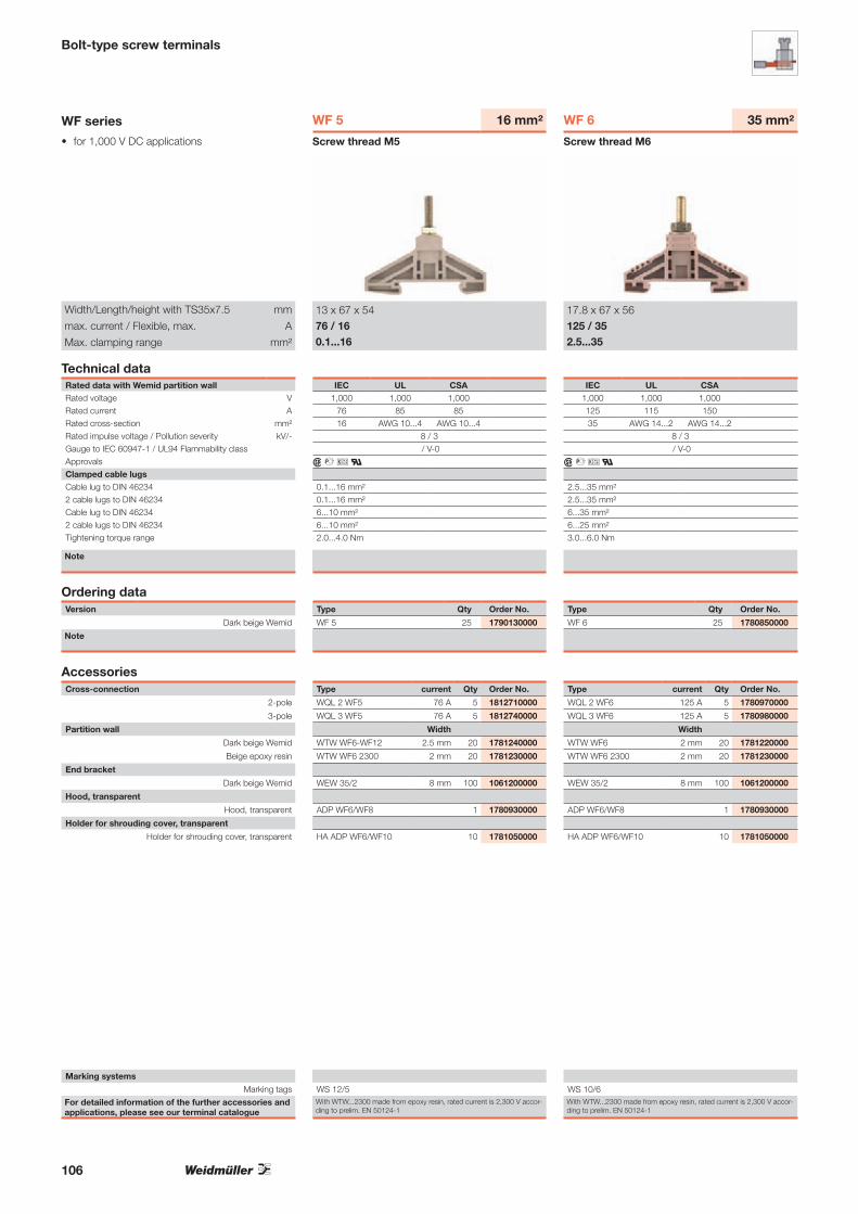
• for 1,000 V DC applications
For detailed information of the further accessories and applications, please see our terminal catalogue
Marking systems
Marking tags
Bolt-type screw terminals
WF series
Technical dataRated data with Wemid partition wallRated voltage VRated current ARated cross-section mm²Rated impulse voltage / Pollution severity kV/-Gauge to IEC 60947-1 / UL94 Flammability classApprovalsClamped cable lugsCable lug to DIN 462342 cable lugs to DIN 46234Cable lug to DIN 46234 2 cable lugs to DIN 46234Tightening torque range
Note
Width/Length/height with TS35x7.5 mm
max. current / Flexible, max. A
Max. clamping range mm²
Version
Dark beige Wemid
Note
Cross-connection
2-pole
3-pole
Partition wall
Dark beige Wemid
Beige epoxy resin
End bracket
Dark beige Wemid
Hood, transparent
Hood, transparent
Holder for shrouding cover, transparent
Holder for shrouding cover, transparent
Screw thread M5
WF 5 16 mm²
13 x 67 x 5476 / 160.1...16
Type Qty Order No.
WF 5 25 1790130000
With WTW...2300 made from epoxy resin, rated current is 2,300 V accor-ding to prelim. EN 50124-1
Type current Qty Order No.
WQL 2 WF5 76 A 5 1812710000
WQL 3 WF5 76 A 5 1812740000
Width
WTW WF6-WF12 2.5 mm 20 1781240000
WTW WF6 2300 2 mm 20 1781230000
WEW 35/2 8 mm 100 1061200000
ADP WF6/WF8 1 1780930000
HA ADP WF6/WF10 10 1781050000
Ordering data
WS 12/5
IEC UL CSA1,000 1,000 1,000
76 85 8516 AWG 10...4 AWG 10...4
8 / 3 / V-0
r # i a
0.1...16 mm²0.1...16 mm²6...10 mm² 6...10 mm²2.0...4.0 Nm
Accessories
Screw thread M6
WF 6 35 mm²
17.8 x 67 x 56125 / 352.5...35
IEC UL CSA1,000 1,000 1,000125 115 15035 AWG 14...2 AWG 14...2
8 / 3 / V-0
r # i a
2.5...35 mm²2.5...35 mm²6...35 mm² 6...25 mm²3.0...6.0 Nm
Type Qty Order No.
WF 6 25 1780850000
With WTW...2300 made from epoxy resin, rated current is 2,300 V accor-ding to prelim. EN 50124-1
Type current Qty Order No.
WQL 2 WF6 125 A 5 1780970000
WQL 3 WF6 125 A 5 1780980000
Width
WTW WF6 2 mm 20 1781220000
WTW WF6 2300 2 mm 20 1781230000
WEW 35/2 8 mm 100 1061200000
ADP WF6/WF8 1 1780930000
HA ADP WF6/WF10 10 1781050000
WS 10/6
106

Bolt-type screw terminals
Screw thread M8
WF 8 50 mm²
22.8 x 67 x 65150 / 502.5...50
IEC UL CSA1,000 1,000 1,000150 150 20050 AWG 14...1/0 AWG 14...1/0
8 / 3 / V-0
r # i a
2.5...50 mm²2.5...50 mm²6...35 mm² 6...35 mm²6.0...12 Nm
The WQL 2, for WF 6 on WF 8, is available under order no. 1808980000.
Type Qty Order No.
WF 8 25 1780860000
With WTW...2300 made from epoxy resin, rated current is 2,300 V accor-ding to prelim. EN 50124-1
Type current Qty Order No.
WQL 2 WF8 150 A 5 1780990000
WQL 3 WF8 150 A 5 1781000000
Width
WTW WF8 2 mm 20 1780900000
WTW WF8 2300 2 mm 20 1780910000
WEW 35/2 8 mm 100 1061200000
ADP WF6/WF8 1 1780930000
HA ADP WF6/WF10 10 1781050000
WS 10/6
Screw thread M10
WF 10 120 mm²
33.8 x 67 x 74269 / 1206...120
IEC UL CSA1,000 1,000 1,000269 255 320120 AWG 10...kcmil 250AWG 10...kcmil 250
8 / 3 / V-0
r # i a
6...120 mm²6...120 mm²10...95 mm² 10...95 mm²10...20 Nm
The WQL 2, for WF 6 on WF 10, is available under order no. 180662000.
Type Qty Order No.
WF 10 20 1780870000
With WTW...2300 made from epoxy resin, rated current is 2,300 V accor-ding to prelim. EN 50124-1
Type current Qty Order No.
WQL 2 WF10 269 A 5 1781010000
WQL 3 WF10 269 A 5 1781020000
Width
WTW WF10/WF12 2 mm 20 1780890000
WTW WF10/WF12 2,300 2 mm 20 1780920000
WEW 35/2 8 mm 100 1061200000
ADP WF10/WF12 1 1780940000
HA ADP WF6/WF10 10 1781050000
WS 10/6
Screw thread M12
WF 12 120 mm²
33.8 x 67 x 72269 / 1206...120
IEC UL CSA1,000 1,000 1,000269 255 320120 AWG 10...kcmil 250AWG 10...kcmil 250
8 / 3 / V-0
r # i a
6...120 mm²6...120 mm²10...95 mm² 10...95 mm²14...31 Nm
Type Qty Order No.
WF 12 20 1780880000
With WTW...2300 made from epoxy resin, rated current is 2,300 V accor-ding to prelim. EN 50124-1
Type current Qty Order No.
WQL 2 WF12 269 A 5 1781030000
WQL 3 WF12 269 A 5 1781040000
Width
WTW WF10/WF12 2 mm 20 1780890000
WTW WF10/WF12 2,300 2 mm 20 1780920000
WEW 35/2 8 mm 100 1061200000
ADP WF10/WF12 1 1780940000
HA ADP WF6/WF10 10 1781050000
WS 10/6
107

• for 1,000 V DC applications
For detailed information of the further accessories and applications, please see our terminal catalogue
Marking systems
Marking tags
Bolt-type screw terminals
WF 2BZ
Technical dataRated data with Wemid partition wallRated voltage VRated current ARated cross-section mm²Rated impulse voltage / Pollution severity kV/-Gauge to IEC 60947-1 / UL94 Flammability classApprovalsClamped cable lugsCable lug to DIN 462342 cable lugs to DIN 46234Cable lug to DIN 46234 2 cable lugs to DIN 46234Tightening torque range
Note
Width/Length/height with TS35x7.5 mm
max. current / Flexible, max. A/mm²
Max. clamping range mm²
Version
Dark beige Wemid
Note
Cross-connection
2-pole
3-pole
Partition wall
Dark beige Wemid
Beige epoxy resin
End bracket
Dark beige Wemid
Hood, transparent
Hood, transparent
Holder for shrouding cover, transparent
Holder for shrouding cover, transparent
Screw thread M6
WF 6/2BZ 35 mm²
17.8 x 67 x 56125 / 352.5...35
Type Qty Order No.
WF 6/2BZ 25 1789770000
With WTW...2,300 made from epoxy resin, rated current is 2300 V, accor-ding to prelim. EN 50124-1
Type current Qty Order No.
WQL 2 WF6 125 A 5 1780970000
WQL 3 WF6 125 A 5 1780980000
Width
WTW WF10/WF12 2 mm 20 1780890000
WTW WF6 2300 2 mm 20 1781230000
WEW 35/2 8 mm 100 1061200000
ADP WF10/WF12 1 1780940000
HA ADP WF6/WF10 10 1781050000
Ordering data
WS 12/5
IEC UL CSA1,000 1,000 1,000125 115 15035 AWG 14...2 AWG 14...2
8 / 3 / V-0
{ #
2.5...35 mm²2.5...35 mm²6...25 mm² 6...25 mm²3.0...6.0 Nm
Accessories
Screw thread M8
WF 8/2BZ 50 mm²
22.8 x 67 x 65150 / 502.5...50
IEC UL CSA1,000 1,000 1,000150 150 20050 AWG 14...1/0 AWG 14...1/0
8 / 3 / V-0
{ #
2.5...50 mm²2.5...50 mm²6...35 mm² 6...35 mm²6.0...12 Nm
Type Qty Order No.
WF 8/2BZ 25 1789780000
With WTW...2,300 made from epoxy resin, rated current is 2300 V, accor-ding to prelim. EN 50124-1
Type current Qty Order No.
WQL 2 WF8 150 A 5 1780990000
WQL 3 WF8 150 A 5 1781000000
Width
WTW WF10/WF12 2 mm 20 1780890000
WTW WF8 2300 2 mm 20 1780910000
WEW 35/2 8 mm 100 1061200000
ADP WF10/WF12 1 1780940000
HA ADP WF6/WF10 10 1781050000
WS 12/5
108

Bolt-type screw terminals
Screw thread M10
WF 10/2BZ 120 mm²
33.8 x 67 x 74269 / 1206...120
IEC UL CSA1,000 1,000 1,000269 230 320120 AWG 10...kcmil 250AWG 10...kcmil 250
8 / 3 / V-0
{ #
6...120 mm²6...120 mm²10...95 mm² 10...95 mm²10...20 Nm
Type Qty Order No.
WF 10/2BZ 20 1789790000
With WTW...2300 made from epoxy resin, rated current is 1500 V up to 70 mm², according to prelim. EN 50124-1
Type current Qty Order No.
WQL 2 WF10 269 A 5 1781010000
WQL 3 WF10 269 A 5 1781020000
Width
WTW WF10/WF12 2 mm 20 1780890000
WTW WF10/WF12 2300 2 mm 20 1780920000
WEW 35/2 8 mm 100 1061200000
ADP WF10/WF12 1 1780940000
HA ADP WF6/WF10 10 1781050000
WS 12/5
109

• for 1,000 V DC applications
Bolt-type screw terminals
WFF series
Technical dataRated data with Wemid partition wallRated voltage VRated current ARated cross-section mm²Rated impulse voltage / Pollution severity kV/-Gauge to IEC 60947-1 / UL94 Flammability classApprovalsClamped cable lugsCable lug to DIN 46234 / 2 cable lugs to DIN 46234Cable lug to DIN 46234 / 2 cable lugs to DIN 46234Tightening torque range
Note
Width/Length/height with TS35x7.5 mm
max. current / Flexible, max. A/mm²
Max. clamping range mm²
Version
Dark beige Wemid
Dark beige Wemid
Blue Wemid
Note
For detailed information on other accessories and ap-plications, refer to the „Accessories“ section
Cross-connection
2-pole
3-pole
Partition wall
Dark beige Wemid
End bracket
Dark beige Wemid
Hood
Hood, dark beige Wemid
Warning triangle for power supply terminals
Screw thread M6
WFF 35 35 mm²
27 x 107 x 54.5150 / 502.5...50
Type Qty Order No.
WFF 35 10 1028300000
WFF 35/AH 5 1029300000
WFF 35 BL 10 1028380000
WAH 35 in blue, order no. 1064480000
Type current Qty Order No.
WQL 2 WFF35 150 A 5 1064900000
WQL 3 WFF35 150 A 5 1065400000
Width
WTW WFF35 2 mm 10 1067100000
WEW 35/1 12 mm 50 1059000000
WAH 35 20 1064460000
WD 1 25 K KARTE A 6 ST 5 1563900000
Ordering data
WS 12/6,5
Marking systems (see assortment in catalogue 7)
Marking tags
IEC UL CSA EN 60079-71,000 1,000 600 1,100125 115 130 10935 AWG 14...2 AWG 14...2 35
8 / 3 / V-0
r u # i ~ x a KEMA 98ATEX1684 U
2.5...50 mm² / 2.5...35 mm²6...25 mm² / 6...25 mm²3.0...6.0 Nm
Accessories
Ex e II T II 2 G D
75
627
Technical drawing
Screw thread M8
WFF 70 70 mm²
32 x 132 x 64232 / 952.5...95
IEC UL CSA EN 60079-71,000 1,000 600 1,100192 175 170 16770 AWG 14...2/0 AWG 14...2/0 70
8 / 3 / V-0
r u # i ~ x a KEMA 98ATEX1684 U
2.5...95 mm² / 2.5...70 mm²16...70 mm² / 16...70 mm²6.0...12 Nm
Ex e II T II 2 G D
Type Qty Order No.
WFF 70 10 1028400000
WFF 70/AH 5 1029400000
WFF 70 BL 10 1028480000
WAH 70 in blue, order no. 1064580000
Type current Qty Order No.
WQL 2 WFF70 232 A 5 1065000000
WQL 3 WFF70 232 A 5 1065500000
Width
WTW WFF70 2 mm 10 1067200000
WEW 35/1 12 mm 50 1059000000
WAH 70 BE 20 1064560000
WD 1 25 K KARTE A 6 ST 5 1563900000
WS 12/6,5
632
100
110
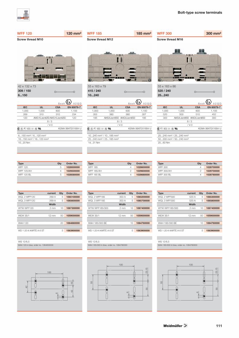
Bolt-type screw terminals
Screw thread M10
WFF 120 120 mm²
42 x 132 x 73309 / 1506...150
IEC UL CSA EN 60079-71,000 1,000 600 1,100269 310 310 234120 AWG 10...kcmil 250AWG 10...kcmil 250 120
8 / 3 / V-0
r u # i ~ x a KEMA 98ATEX1684 U
6...150 mm² / 6...120 mm²16...150 mm² / 16...120 mm²10...20 Nm
Ex e II T II 2 G D
Type Qty Order No.
WFF 120 5 1028500000
WFF 120/AH 4 1029500000
WFF 120 BL 5 1028580000
WAH 120 in blue, order no. 1064650000
Type current Qty Order No.
WQL 2 WFF120 269 A 5 1065100000
WQL 3 WFF120 269 A 5 1065600000
Width
WTW WFF120 2 mm 10 1067300000
WEW 35/1 12 mm 50 1059000000
WAH 120 20 1064660000
WD 1 25 K KARTE A 6 ST 5 1563900000
WS 12/6,5
100
16426
42
Screw thread M12
WFF 185 185 mm²
55 x 163 x 79415 / 24010...240
IEC UL CSA EN 60079-71,000 1,000 600 1,100353 380 360 307185 AWG 8...kcmil 500 AWG 8...kcmil 500 185
8 / 3 / V-0
r u # i ~ x a KEMA 98ATEX1684 U
10...240 mm² / 10...185 mm²25...240 mm² / 25...185 mm²14...31 Nm
Ex e II T II 2 G D
Type Qty Order No.
WFF 185 4 1028600000
WFF 185/AH 2 1029600000
WFF 185 BL 4 1028680000
WAH 185/300 in blue, order no. 1064780000
Type current Qty Order No.
WQL 2 WFF185 353 A 5 1065200000
WQL 3 WFF185 353 A 5 1065700000
Width
WTW WFF185/300 2 mm 10 1067400000
WEW 35/1 12 mm 50 1059000000
WAH 185/300 BE 10 1064760000
WD 1 25 K KARTE A 6 ST 5 1563900000
WS 12/6,5
100
55
55
6
23.1
5
Screw thread M16
WFF 300 300 mm²
55 x 163 x 86520 / 24025...240
IEC UL CSA EN 60079-71,000 1,000 600 1,100520 500 510 452300 AWG 6...kcmil 600 AWG 6...kcmil 600 300
8 / 3 / V-0
r # i ~ x a KEMA 98ATEX1684 U
25...240 mm² / 25...240 mm²50...300 mm² / 50...240 mm²25...60 Nm
Ex e II T II 2 G D
Type Qty Order No.
WFF 300 4 1028700000
WFF 300/AH 2 1029700000
WFF 300 BL 4 1028780000
WAH 185/300 in blue, order no. 1064780000
Type current Qty Order No.
WQL 2 WFF300 520 A 5 1065300000
WQL 3 WFF300 520 A 5 1065800000
Width
WTW WFF185/300 2 mm 10 1067400000
WEW 35/1 12 mm 50 1059000000
WAH 185/300 BE 10 1064760000
WD 1 25 K KARTE A 6 ST 5 1563900000
WS 12/6,5
100
55
55
6
23.1
5
111

• for 1,000 V DC applications
WPDB 70/16 1/10 70/16 mm²
Supply terminal
70 mm2 16 mm2
16 mm2
• Space-saving design• Modular or 3-phase block versions• Easy to use• IP20 degree of protection• For TS 35 rail or direct mounting• High short-circuit protection• Parallel cross-connection with 5 x 15 mm busbar
175 A
45 x 55 (71) x 42228 g
69017570 / 162,5 KV / 3V-0
223A B C1
16 … 7016 … 7016 … 7016 … 7016 … 70125M10M515 … 16A B C10
2,5 … 162,5 … 162,5 … 162,5 … 162,5 … 1663M6M310 … 12
Type Qty. Order No.
WPDB 70/16 1/10 1 1939460000
Type Qty. Order No.
SK-S 2.0-8.0 1 9008860000
LM MT300 15 x 9 GE 1 1882890000
▲
4.2
54
▲
▲
▲
4.2
61.5
▲
▲
22.8
▲
▲22.8
▲
▲
60.6
▲
▲
17.5
WPDB 16/6 3/4
WPDB 35-16/16 1-1/6
WPDB 70/16 1/10
Technical data
Max. currentDimensionsWidth / Length (incl. mounting) / Hight (mm) with TS 35x7.5WeightIEC rated 60 947-7-1Rated voltage VRated current ARated cross-section in-/output mm²Rated impulse voltage / Pollution severityUL94 Flammability ClassFurther technical dataShort-circuit strength (peak value) kAShort-circuit strength > 1 s kAInputsNo. of connectionsClampable conductors:
„e“ solid H07V-U mm²„m“ stranded H07V-R mm²„f“ flexible H07V-K mm²„f“ flexible H07V-K and ferrule acc. to DIN 46 228/1 mm²„f“ flexible H07V-K and ferrule with plastic insul. Collar mm²Diameter mm
Tightening torque NmClamping screwBlade sizeStripping length mmOutputsNo. of connectionsClampable conductors:
„e“ solid H07V-U mm²„m“ stranded H07V-R mm²„f“ flexible H07V-K mm²„f“ flexible H07V-K and ferrule acc. to DIN 46 228/1 mm²„f“ flexible H07V-K and ferrule with plastic insul. Collar mm²Diameter mm
Tightening torque NmClamping screwBlade sizeStripping length mmUL/CSA rated dataVoltage/current/conductor size ULVoltage/current/conductor size CSA
Version
dark beige Wemid
Ordering Data
Screwdrivers
Crosshead screwdriver, Pozidriv type
Crosshead screwdriver, Pozidriv type
7-piece hexagon wrench set
Labelling systems
Marking labels for laser printer
Accessories
112

WEW 35/2
EW 35
ZEW 35/2
MEW 35/1
WEW 35/1
End bracket
EW 15/2
EW 15
ZEW 15
Polyamide 66. screw-in Colour Torque Qty. Order No.EW 15 beige 0.4 Nm 50 0382860000
Polyamide with fibreglass, screw-inEW 15/2 dark beige 0.4 Nm 50 1071900000
Polyamide 66, screwlessZEW 15 beige 20 7920340000
Polyamide 66, screw-in Colour Torque Qty. Order No.EWK 2 beige 1.2 Nm 50 0199360000
EWK 1 beige 1.2 Nm 50 0206160000
Polyamide with fibreglass, screw-inWEW 32/1 dark beige 0.5 Nm 50 1067600000
WEW 32/1 SW black 0.5 Nm 50 1272980000
Metal, screwableMEW 1/32 silver 2 Nm 20 0445600000
Polyamide with fibreglass,
screw-in
Colour Torque Qty. Order No.
WEW 35/1 dark beige 1.2 Nm 50 1059000000
WEW-35/2 dark beige 0.5 Nm 100 1061200000
WEW 35/1 GR grey 1.2 Nm 50 1227890000
WEW 35/1 SW black 1.2 Nm 50 1162600000
WEW 35/2 GR grey 0.5 Nm 100 1859200000
WEW 35/3 SW black 0.5 Nm 100 1061210000
20 9540000000Polyamide 66, screwlessZEW (6 mm) beige 20 9540000000
ZEW 35/2 (8 mm) beige 20 8630740000
ZEW 35 GR grey 20 1238040000
ZEW 35/2 GR grey 20 1227850000
ZEW 35/2 SW black 20 1162610000
Polyamide 66, screw-inEW 35 beige 0.5 Nm 50 0383560000
EW 35 GR grey 0.5 Nm 50 0383530000
EW 35 DB (V0) dark beige 50 1269050000
silver 5.5 Nm 10 1805610000Metal, screwableMEW 35/1 silver 5.5 Nm 10 1805610000
WEW 32/1
EWK 1
EWK 2
MEW 1/32
For TS 15 terminal rail
For terminal rail TS 32
For terminal rail TS 35
113

Installation instructions
The use of aluminium conductors
Weidmüller modular terminals are suitable for the direct connection of solid round and sector aluminium conductors. In contrast to copper, aluminium exhibits certain characteristics that must be taken into account when using this material as a conductor in electrical engineering.
A thin, non-conductive layer of oxide forms immediately on the unprotected surface of the aluminium as soon as it is exposed to the air. This layer increases the contact resistance between the aluminium conductor and the current bar of the modular terminal. And that, in unfavourable conditions, can lead to poor contact. And in stranded conductors the contact resistances of the individual strands are added together. Despite these disadvan-tages, aluminium conductors can be con-nected to Weidmüller modular terminals, provided the reduced rated currents for aluminium conductors and the following in-stallation conditions are adhered to.
1. Scrape the stripped end of the conduc- tor carefully, eg. with a knife, to remove the layer of oxide. Caution: Do not use brushes, files or emery paper because particles of alumi-nium can be deposited on other con-ductors.
2. After removing the layer of oxide, coat the end of the conductor immediately with a neutral grease, e.g. acid- and al-kali-free Vaseline, and connect it to the terminal immediately.
3. Repeat the above procedure if at any time the conductor is disconnected and reconnected.
4. The above installation instructions are valid for solid round or sector aluminium conductors only.
Solid round and sector conductors
Terminal type Rated cross-section Reduced rated Clamping screw Tightening torque
current when thread size
connecting an
aluminium conductor
W-Series mm2 „A“ Nm
WDU 4 4 27 M 3 0.6-1.0
WDU 6 6 35 M 3.5 1.2-1.6
WDU 10 10 48 M 4 2.0-2.4
WDU 16 16 64 M 5 3.0-4.0
WDU 35 35 105 M 6 4.0-6.0
WDU 70 70 163 M 8 10.0-12.0
WDU 120 120 230 M 10 15.0-20.0
WDU 240 240 – M 10 12.0-20.0
Stranded conductors
W-Series
WFF 35 35 105 M 6 3.0-6.0
WFF 70 70 163 M 8 6.0-12.0
WFF 120 120 230 M 10 10.0-20.0
WFF 185 185 300 M 12 15.5-31.0
WFF 300 300 409 M 16 30.0-60.0
Installation advice when using flat cable lugs When tightening the terminal it is advisab-le to hold the conductor to prevent defor-mation of the terminal rail and to avoid twisting the foot of the terminal. When connecting stranded aluminium conductors to modular terminals, it is advisable to use an aluminium cable lug chosen to match the type of conductor and connected according to the instruc-tions of the cable lug manufacturer. It is
necessary to fit a copper-plated alumini-um washer between the aluminium cable lug and the copper current bar of the mo-dular terminal. This is the only way of gua-ranteeing a reliable transition between the copper and the aluminium. Fit the washer in such a way that the copper side is in contact with the current bar, and the alu-minium side in contact with the cable lug.
Fixing screw
Current bar
1 3
24
5Al side
Al conductor
Cu-plated Al washer
Al cable lug
Cu side
1
2
3
4
5
114

115

Space saving switch-mode power supplies for use in combiner boxes and other applications such as drives for example
PRO-M = Power-Reliable-Optimized
The solid, very narrow metal housing of the 10 different versions of the24 V DC supply enable installation without lateral spacing, thereby savingspace on the DIN rail. AC and DC wide-range inputs and a broadtemperature range allow universal use. Up to 5 modules can be wired in parallel without a diode module in order to flexibly increase the power output. Thanks to its high efficiency, overload resistance and high performance reserves, the PRO-M is the reliable power supply in all applications – and all that in an entry-level product.
INSTAPOWERThe particularly compact series with Insta-housing shape for standard applications up to 48 W.
Thanks to wide-range input (both DC as well as AC voltages can be used; no switching required) and extensive approvals (UL/CSA and GL (EMC 1 - bridge)).
International use
Module power can be increased by connecting up to five power supplies in parallel without diode module.
Parallel connection
Switched-mode power supply units
AC / DC
Switch-mode power supplies PRO-M and INSTAPOWER
116

Switched-mode power supply units
The right power supply for every application:1-phase 3 A, 5 A, 7.5 A, 10 A, 20 A, 40 A and 3-phase 5 A, 10 A, 20 A, 40 A.
Wide choice
Wide temperature range from–25 °C … +70 °C.
Robust
+70 °C to–25 °C
Rated load
Temperature
120 %
100 %
45 °C 60 °C 70 °C
Power reserve
Powerful
With additional power reserves at standard temperatures.
Space-saving configuration in the switching cabinet through very narrow housing construction and side-by-side connectability.
Narrowfrom 33 mm
For further information, please ask for our catalogue:
Power SuppliesOrder number: 1282390000
4.3
Ele
ktro
nik
– S
tro
mve
rso
rgu
ng
enK
atal
og
201
1|20
12
Elektronik StromversorgungenKatalog
2011 |2012
4.3KA
TA
LOG
Bestellnummer:1282380000/05/2011/SMMD
www.weidmueller.com
ÄgyptenArgentinienAserbaidschanAustralienBahrainBelgienBosnien undHerzegowinaBrasilienBulgarienChileChinaCosta RicaDänemarkDeutschlandEcuadorEstlandFinnlandFrankreichGriechenlandGroßbritannienHongkong IndienIndonesienIranIrlandIslandIsraelItalienJapanJordanien
KanadaKasachstanKatarKolumbienKoreaKroatienKuwaitLettlandLibanonLitauenLuxemburgMalaysiaMaltaMazedonienMexikoMoldauNeuseelandNiederlandeNorwegenOmanÖsterreichPakistanPeruPhilippinenPolenPortugalRumänienRusslandSaudi-ArabienSchwedenSchweiz
SerbienSingapurSlowakeiSlowenienSpanienSüdafrikaTaiwanThailandTschechienTunesienTürkeiUkraineUngarnUruguayUsbekistanVenezuelaVereinigteArabischeEmirateVereinigteStaatenVietnamWeißrussland
Weidmüller ist weltweit führender Anbieter vonLösungen für die elektrische Verbindung, Übertragungund Wandlung von Energie, Signalen und Daten imindustriellen Umfeld.
Das Unternehmen mit Hauptsitz in Detmold entwickelt, produziert und vertreibt weltweit Produkte der elektrischen Verbindungstechnik und der Elektronik.Über ein Netzwerk von Applikationsspezialisten bietetWeidmüller Engineering-Dienstleistungen an undentwickelt anwendungsspezifische Lösungen.
Das gesamte Produkt- und Leistungsspektrum sichertunseren Kunden und Weidmüller in gleicher Weisedauerhaft Wettbewerbs- und Wertvorteile.
117

Switch-mode power supplies PRO-M
connectPowerPRO-M
Two-Phase operation also possible
Permissible maximum continuous current [A]
Max. limiting average on state current [A]Type\Temp. 45°C 50°C 55°C 60°C 65°C 70°C1ph 24V / 3A 3.6 3.4 3.2 3 2.6 2.3
1ph 24V / 5A 6 5.7 5.3 5 4.4 3.8
1ph 24V / 7.5A 9 8.5 8 7.5 6.6 5.6
1ph 24V / 10A 12 11.3 10.7 10 8.8 7.5
1ph 24V / 20A 24 22.7 21.3 20 17.5 15
1ph 24V / 40A 48 45.3 42.7 40 35 30
3ph 24V / 5A 6 5.7 5.3 5 4.4 3.8
3ph 24V / 10A 12 11.3 10.7 10 8.8 7.5
3ph 24V / 20A 24 22.7 21.3 20 17.5 15
3ph 24V / 40A 48 45.3 42.7 40 35 30
Technical dataGeneral technical dataCurrent limiting > 120 % INAmbient temp. operating / storage temperature –25 °C … +70 °C / –40 °C … +85 °C
Max. perm. air humidity (operation) 5 %…95 % RH
Degree of protection IP20
Class of protection I, with PE connection
Pollution degree 2
Insulation voltage 3 kV I/O / 2 kV I/earth / 0.5 kV O/earth
MTBF > 500,000 h acc. to IEC 1709 (SN29500)
Protection against reverse voltages from the load 30…35 V DC
Parallel connection option yes, without diode module
Housing version metal, corrosion resistant
Indication operation, green LED
Mounting position, installation notice horizontal on mounting rail TS35, 50 mm spacing top and bottom for free
air circulation, can be mounted side by side with no space in between
EMC / shock / vibrationNoise emission acc. to EN55022 Class B
Noise immunity tests acc. to EN61000-4-2 (ESD), EN61000-4-3 und EN61000-4-8 (Fields),
EN61000-4-4 (Burst), EN61000-4-5 (Surge), EN610004-6 (con-
ducted), EN61000-4-11 (Dips)
Limiting of mains voltage harmonic currents Acc. to EN 61000-3-2
Resistance against vibration and shock Acc. to EN50178, shock: 5g in all directions
Electrical safety (applied standards)Electrical equipment of machines Acc. to EN60204
Safety transformers for switched-mode power units Acc. to EN61558-2-17
Machinery with electronic equipment Acc. to EN50178 / VDE0160
Safety extra-low voltage SELV acc. to EN60950, PELV acc. to EN60204
Protective separation / protection against electrical shock VDE0100-410 / acc. to DIN57100-410
Protection against dangerous shock currents Acc. to VDE0106-101
Project-planning dataType 24 V / 3 A 24 V / 5 A 24 V / 7.5 A 24 V / 10 A 24 V / 20 A 24 V / 40 A 24 V / 5 A 24 V / 10 A 24 V / 20 A 24 V / 40 A
1 - phase 3 - phase
Rated input voltage 100...240 V AC 3 x 400...500 V AC
Mains voltage range 85...264 V AC 3 x 320...575 V AC
Mains input current 1.3...0.6 A 2.1...0.9 A 2.1...0.9 A 2.8...1.2 A 5.6...2.4 A 11.1...4.7 A 0.3...0.28 A 0.55...0.5 A 1.0...0.9 A 2.5...2.0 A
Rec. fuse [char..] 2 A / D I / II 4 A / D I / II 6 A / D I / II 6 A / D I / II 10 A / D I / II 16 A / D I / II 2 A / D I / II 2 A / D I / II 2 A / D I / II 4 A / D I / II
6 A, [B] 6 A, [B] 10 A, [B] 10 A, [B] 20 A, [B] 25 A, [B] - - - 10 A, [B]
2...4 A, [C] 3...5 A, [C] 5...10 A, [C] 5...10 A, [C] 10...12 A, [C] 14...16 A, [C] 1...2 A, [C] 2...3 A, [C] 3...5 A, [C] 6...8 A, [C]
Efficiency @ 230 V AC, @ 3x400 V AC 90 % 90 % 91 % 90 % 90 % 91 % 90 % 90 % 90 % 91 %
Rated power loss [W] 8 W 13 W 18 W 27 W 53 W 95 W 13 W 27 W 53 W 95 W
Installation width mm 33 40 50 60 121 180 40 60 121 180
Input terminals Screw connection
Conductor, solid min/max mm2 0.5...6 0.5...6 0.08...4 0.5...6 0.5...6
Conductor, flexible min/max mm2 0.5...2.5 0.5...2.5 0.5...2.5 0.5...2.5 0.5...2.5
Conductor, AWG/kcmil min/max 26 / 12 26 / 10 28 / 12 26 / 12 26 / 12
Output terminals Screw connection
Number plus/minus 2 / 2 2 / 3
Conductor, solid min/max mm2 0.5...6 0.5...6 0.5...16 0.5...6 0.5...6 0.5...16
Conductor, flexible min/max mm2 0.5...2.5 0.5...2.5 2.5...10 0.5...2.5 0.5...2.5 2.5...10
Conductor, AWG/kcmil min/max 26 / 12 26 / 10 22 / 6 26 / 12 26 / 10 22 / 6
+
–
L (+)
N (–)
PE DCAC
+
–
L1 (+)
L2 (–)
L3
PE DCAC
118

Switch-mode power supplies PRO-M
connectPower PRO-M
H
L
W
Technical dataInputrated input voltageInput voltage range ACFrequency range ACDC input voltage rangeAC current consumptionDC current consumptionInput fuse (internal) / making currentRecommended back-up fuse*)
Outputrated output voltageOutput voltageresidual ripple, breaking spikesRated (nominal) output current @ UNom
continous output current @ 24 V DCPowerboost @ 24 V DC, 60 °CGeneral dataDegree of efficiencyPower factor (approx.)AC failure bridging time @ INom
Parallel connection optionLength x width x heightWeightApprovals
Connection dataConductor connection systemNumber of terminalsWire cross-section, rigid min/max mm²Wire cross-section, flexible min/max mm²Wire cross-section, AWG/kcmil min/max
Note
Ordering dataConnection system
Screw connection
Note
Accessories
CP M SNT 70 W 24 V 3 A
+
–
L (+)
N (–)
PE DCAC
With DC connection, note polarity
100...240 V AC (wide-range input) 85…264 V AC (Derating @ 100 V AC: 2.5 % / V) 47...63 Hz 80…370 V DC (Derating @ 120 V DC: 1 % / V) 0.6 A @ 230 V AC / 1.1 A @ 115 V AC 0.25 A @ 370 V DC / 0.7 A @ 120 V DCYes / max. 40 A2 A / DI, safety fuse
6 A, Char. B, circuit breaker
2...4 A, Char. C, circuit breaker
24 V DC ± 1 % 22.5...29.5 V DC (adjustable via potentiometer on front) < 50 mVpp @ 24 V DC, IN3 A @ 60 °C 3.6 A @ 45 °C, 3.2 A @ 55 °C, 2.3 A @ 70 °C 3.6 A for 1 min, ED = 5 %
90 % @ 230 V AC / 88 % @ 115 V AC > 0.6 @ 230 V AC / > 0,65 @ 115 V AC > 100 ms @ 230 V AC / > 20 ms @ 115 V ACyes, max. 5125 / 33 / 130 mm0.57 kg
CE; cURus; cULus; C-Tick
Input OutputScrew connection Screw connection3 for L/N/PE 4 (++ / --)0.5 / 6 0.5 / 60.5 / 2.5 0.5 / 2.526 / 12 26 / 12*) Recommendation applies only for AC operation; the max. permissible operating voltage must be observed in all cases!
Type Qty. Order No.
CP M SNT 70W 24V 3A 1 8951330000
CP M SNT 120 W 24 V 5 A
100...240 V AC (wide-range input) 85…264 V AC (Derating @ 100 V AC: 2.5 % / V*) 47...63 Hz 80…370 V DC (Derating @ 120 V DC: 1 % / V) 1.1 A @ 230 V AC / 2.0 A @ 115 V AC 0.4 A @ 370 V DC / 1.2 A @ 120 V DCYes / max. 40 A4 A / DI, safety fuse
6 A, Char. B, circuit breaker
3...5 A, Char. C, circuit breaker
24 V DC ± 1 % 22.5...29.5 V DC (adjustable via potentiometer on front) < 50 mVpp @ 24 V DC, IN5 A @ 60 °C 6.0 A @ 45 °C, 5.3 A @ 55 °C, 3.8 A @ 70 °C 6 A for 1 min, ED = 5 %
90 % @ 230 V AC / 88 % @ 115 V AC > 0.5 @ 230 V AC / > 0.6 @ 115 V AC > 100 ms @ 230 V AC / > 20 ms @ 115 V ACyes, max. 5125 / 40 / 130 mm0.7 kg
CE; cURus; cULus; C-Tick
+
–
L (+)
N (–)
PE DCAC
With DC connection, note polarity
Input OutputScrew connection Screw connection3 for L/N/PE 5 (++ / ---)0.5 / 6 0.5 / 60.5 / 2.5 0.5 / 2.526 / 12 26 / 12*) Recommendation applies only for AC operation; the max. permissible operating voltage must be observed in all cases!
Type Qty. Order No.
CP M SNT 120W 24V 5A 1 8951340000
119

Switch-mode power supplies PRO-M
connectPower PRO-M
H
L
W
Technical dataInputrated input voltageInput voltage range ACFrequency range ACDC input voltage rangeAC current consumptionDC current consumptionInput fuse (internal) / making currentRecommended back-up fuse
Outputrated output voltageOutput voltageresidual ripple, breaking spikesRated (nominal) output current @ UNom
continous output current @ 24 V DCPowerboost @ 24 V DC, 60 °CGeneral dataDegree of efficiencyPower factor (approx.)AC failure bridging time @ INom
Parallel connection optionLength x width x heightWeightApprovals
Connection dataConductor connection systemNumber of terminalsWire cross-section, rigid min/max mm²Wire cross-section, flexible min/max mm²Wire cross-section, AWG/kcmil min/max
Note
Ordering dataConnection system
Screw connection
Note
Accessories
CP M SNT 180 W 24 V 7.5 A
+
–
L (+)
N (–)
PE DCAC
With DC connection, note polarity
100...240 V AC (wide-range input) 85…264 V AC (Derating @ 100 V AC: 2.5 % / V) 47...63 Hz 80…370 V DC (Derating @ 120 V DC: 1 % / V) 0.9 A @ 230 V AC / 1.8 A @ 115 V AC 0.6 A @ 370 V DC / 1.7 A @ 120 V DCYes / max. 40 A6 A / DI, safety fuse
10 A, Char. B, circuit breaker
6 A, Char. C, circuit breaker
24 V DC ± 1 % 22.5...29.5 V DC (adjustable via potentiometer on front) < 50 mVpp @ 24 V DC, IN7,5 A @ 60 °C 9.0 A @ 45 °C, 8.0 A @ 55 °C, 5.6 A @ 70 °C 9 A for 1 min, ED = 5 %
91 % @ 230 V AC / 88 % @ 115 V AC > 0.94 @ 230 V AC / > 0.99 @ 115 V AC > 20 ms @ 230 V AC / > 20 ms @ 115 V ACyes, max. 5150 / 50 / 130 mm1.05 kg
CE; cURus; cULus; C-Tick
Input OutputScrew connection Screw connection3 for L/N/PE 5 (++ / ---)0.5 / 6 0.5 / 60.5 / 2.5 0.5 / 2.526 / 12 26 / 12*) Recommendation applies only for AC operation; the max. permissible operating voltage must be observed in all cases!
Type Qty. Order No.
CP M SNT 180W 24V 7,5A 1 8951350000
CP M SNT 250 W 24 V 10 A
100...240 V AC (wide-range input) 85…264 V AC (Derating @ 100 V AC: 2.5 % / V) 47...63 Hz 80…370 V DC (Derating @ 120 V DC: 1 % / V) 1.2 A @ 230 V AC / 2.4 A @ 115 V AC 0.8 A @ 370 V DC / 2.3 A @ 120 V DCYes / max. 12 A4 A / DI,safety fuse
10 A, Char. B, circuit breaker
3...4 A, Char. C, circuit breaker
24 V DC ± 1 % 22.5...29.5 V DC (adjustable via potentiometer on front) < 50 mVpp @ 24 V DC, IN10 A @ 60 °C 12 A @ 45 °C, 10.7 A @ 55 °C, 7.5 A @ 70 °C 12 A for 1 min, ED = 5 %
90 % @ 230 V AC / 87 % @ 115 V AC > 0.99 @ 230 V AC / > 0.97 @ 115 V AC > 20 ms @ 230 V AC / > 20 ms @ 115 V ACyes, max. 5150 / 60 / 130 mm1.2 kg
CE; cURus; cULus; C-Tick
+
–
L (+)
N (–)
PE DCAC
With DC connection, note polarity
Input OutputScrew connection Screw connection3 for L/N/PE 5 (++ / ---)0.5 / 6 0.5 / 60.5 / 2.5 0.5 / 2.526 / 12 26 / 12*) Recommendation applies only for AC operation; the max. permissible operating voltage must be observed in all cases!
Type Qty. Order No.
CP M SNT 250W 24V 10A 1 8951360000
120

Switch-mode power supplies PRO-M
connectPower PRO-M
H
L
W
Technical dataInputrated input voltageInput voltage range ACFrequency range ACDC input voltage rangeAC current consumptionDC current consumptionInput fuse (internal) / making currentRecommended back-up fuse
Outputrated output voltageOutput voltageresidual ripple, breaking spikesRated (nominal) output current @ UNom
continous output current @ 24 V DCPowerboost @ 24 V DC, 60 °CGeneral dataDegree of efficiencyPower factor (approx.)AC failure bridging time @ INom
Parallel connection optionLength x width x heightWeightApprovals
Connection dataConductor connection systemNumber of terminalsWire cross-section, rigid min/max mm²Wire cross-section, flexible min/max mm²Wire cross-section, AWG/kcmil min/max
Note
Ordering dataConnection system
Screw connection
Note
Accessories
CP M SNT 500 W 24 V 20 A
+
–
L (+)
N (–)
PE DCAC
With DC connection, note polarity
100...240 V AC (wide-range input) 85…264 V AC (Derating @ 100 V AC: 2.5 % / V) 47...63 Hz 80…370 V DC (Derating @ 120 V DC: 1 % / V) 2.4 A @ 230 V AC / 4.8 A @ 115 V AC 1.5 A @ 370 V DC / 4.6 A @ 120 V DCYes / max. 5 A6 A / DI, safety fuse
16 A, Char. B, circuit breaker
6…8 A, Char. C, circuit breaker
24 V DC ± 1 % 22.5...29.5 V DC (adjustable via potentiometer on front) < 50 mVpp @ 24 V DC, IN20 A @ 60 °C 24 A @ 45 °C, 22.7 A @ 55 °C, 15 A @ 70 °C 24 A for 1 min, ED = 5 %
90 % at 230 V AC / > 85 % at 115 V AC > 0.98 @ 230 V AC / > 0.99 @ 115 V AC > 20 ms @ 230 V AC / > 20 ms @ 115 V ACyes, max. 3150 / 121 / 130 mm2.2 kg
CE; cURus; cULus; C-Tick
Input OutputScrew connection Screw connection3 for L/N/PE 5 (++ / ---)0.5 / 6 0.5 / 60.5 / 2.5 0.5 / 2.526 / 10 26 / 10*) Recommendation applies only for AC operation; the max. permissible operating voltage must be observed in all cases!
Type Qty. Order No.
CP M SNT 500W 24V 20A 1 8951370000
CP M SNT 1000 W 24 V 40 A
100...240 V AC (wide-range input) 85…264 V AC (Derating @ 100 V AC: 2.5 % / V) 47...63 Hz 80…370 V DC (Derating @ 120 V DC: 1 % / V) 4.7 A @ 230 V AC / 9.6 A @ 115 V AC 2.9 A @ 370 V DC / 9.1 A @ 120 V DCYes / max. 5 A16 A / DI, safety fuse
20 A, Char. B, circuit breaker
16 A, Char. C, circuit breaker
24 V DC ± 1 % 22.5...29.5 V DC (adjustable via potentiometer on front) < 50 mVpp @ 24 V DC, IN40 A @ 60 °C 48 A @ 45 °C, 42.7 A @ 55 °C, 30 A @ 70 °C 48 A for 1 min, ED = 5 %
91 % @ 230 V AC / 88 % @ 115 V AC > 0.99 @ 230 V AC / > 0.99 @ 115 V AC > 20 ms @ 230 V AC / > 20 ms @ 115 V ACyes, max. 3150 / 180 / 130 mm3.9 kg
CE; cURus; cULus; C-Tick
+
–
L (+)
N (–)
PE DCAC
With DC connection, note polarity
Input OutputScrew connection Screw connection3 for L/N/PE 5 (++ / ---)0.5 / 6 0.5 / 160.5 / 2.5 2.5 / 1026 / 10 22 / 6*) Recommendation applies only for AC operation; the max. permissible operating voltage must be observed in all cases!
Type Qty. Order No.
CP M SNT 1000W 24V 40A 1 8951380000
121

Switch-mode power supplies PRO-M
connectPower PRO-M
H
L
W
Technical dataInputrated input voltageInput voltage range ACFrequency range ACDC input voltage rangeAC current consumptionDC current consumptionInput fuse (internal) / making currentRecommended back-up fuse
Outputrated output voltageOutput voltageresidual ripple, breaking spikesRated (nominal) output current @ UNom
continous output current @ 24 V DCPowerboost @ 24 V DC, 60 °CGeneral dataDegree of efficiencyPower factor (approx.)AC failure bridging time @ INom
Parallel connection optionLength x width x heightWeightApprovals
Connection dataConductor connection systemNumber of terminalsWire cross-section, rigid min/max mm²Wire cross-section, flexible min/max mm²Wire cross-section, AWG/kcmil min/max
Note
Ordering dataConnection system
Screw connection
Note
Accessories
CP M SNT3 120 W 24 V 5 A
+
–
L1 (+)
L2 (–)
L3
PE
With DC connection, note polarity
Two-phase operation also possible
DCAC
3 x 400...3 x 500 V AC (wide-range input) 3 x 320...3 x 575 V AC / 2 x 360...2 x 575 V AC 47...63 Hz 450...800 V DC (max. 500 V DC acc. to UL508) 0.28 A @ 3 x 500 V AC / 0.3 A @ 3 x 400 V AC 0.18 A @ 800 V DC / 0.3 A @ 450 V DCNo / max. 50 A2 A / DI, safety fuse
2...3 A, Char. C, circuit breaker
24 V DC ± 1 % 22.5...29.5 V DC (adjustable via potentiometer on front) < 50 mVpp @ 24 V DC, IN5 A @ 60 °C 6.0 A @ 45 °C, 5.3 A @ 55 °C, 3.8 A @ 70 °C 6 A for 1 min, ED = 5 %
89 % @ 3 x 500 V AC / 90 % @ 3 x 400 V AC > 0.55 @ 3 x 500 V AC / > 0.65 @ 3 x 400 V AC > 50 ms @ 3 x 500 V AC / > 20 ms @ 3 x 400 V ACyes, max. 5125 / 40 / 130 mm0.7 kg
CE; cURus; cULus; C-Tick
Input OutputScrew connection Screw connection4 for L1/L2/L3/PE 5 (++ / ---)0.08 / 4 0.5 / 60.5 / 2.5 0.5 / 2.528 / 12 26 / 12*) Recommendation applies only for AC operation; the max. permissible operating voltage must be observed in all cases!
Type Qty. Order No.
CP M SNT3 120W 24V 5A 1 8951390000
CP M SNT3 250 W 24 V 10 A
3 x 400...3 x 500 V AC (wide-range input) 3 x 320...3 x 575 V AC / 2 x 360...2 x 575 V AC 47...63 Hz 450...800 V DC (max. 500 V DC acc. to UL508) 0.5 A @ 3 x 500 V AC / 0.55 A @ 3 x 400 V AC 0.35 A @ 800 V DC / 0.6 A @ 450 V DCNo / max. 50 A2 A / DI, safety fuse
2...3 A, Char. C, circuit breaker
24 V DC ± 1 % 22.5...29.5 V DC (adjustable via potentiometer on front) < 50 mVpp @ 24 V DC, IN10 A @ 60 °C 12 A @ 45 °C, 10.7 A @ 55 °C, 7.5 A @ 70 °C 12 A for 1 min, ED = 5 %
89 % @ 3 x 500 V AC / 90 % @ 3 x 400 V AC > 0.65 @ 3 x 500 V AC / > 0.75 @ 3 x 400 V AC > 40 ms @ 3 x 500 V AC / > 20 ms @ 3 x 400 V ACyes, max. 5150 / 60 / 130 mm1.25 kg
CE; cURus; cULus; C-Tick
+
–
L1 (+)
L2 (–)
L3
PE
With DC connection, note polarity
Two-phase operation also possible
DCAC
Input OutputScrew connection Screw connection4 for L1/L2/L3/PE 5 (++ / ---)0.5 / 6 0.5 / 60.5 / 2.5 0.5 / 2.526 / 12 26 / 12*) Recommendation applies only for AC operation; the max. permissible operating voltage must be observed in all cases!
Type Qty. Order No.
CP M SNT3 250W 24V 10A 1 8951400000
122
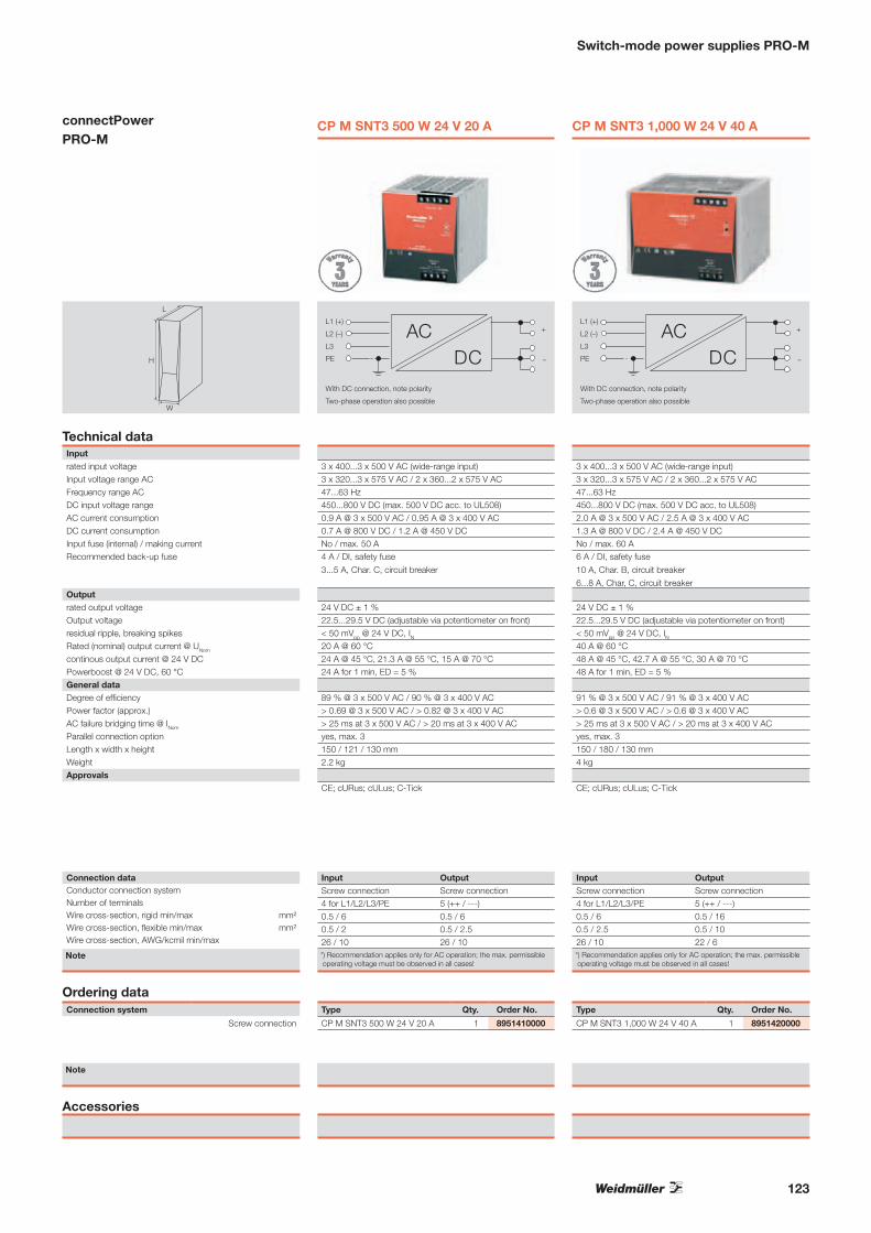
Switch-mode power supplies PRO-M
connectPower PRO-M
H
L
W
Technical dataInputrated input voltageInput voltage range ACFrequency range ACDC input voltage rangeAC current consumptionDC current consumptionInput fuse (internal) / making currentRecommended back-up fuse
Outputrated output voltageOutput voltageresidual ripple, breaking spikesRated (nominal) output current @ UNom
continous output current @ 24 V DCPowerboost @ 24 V DC, 60 °CGeneral dataDegree of efficiencyPower factor (approx.)AC failure bridging time @ INom
Parallel connection optionLength x width x heightWeightApprovals
Connection dataConductor connection systemNumber of terminalsWire cross-section, rigid min/max mm²Wire cross-section, flexible min/max mm²Wire cross-section, AWG/kcmil min/max
Note
Ordering dataConnection system
Screw connection
Note
Accessories
CP M SNT3 500 W 24 V 20 A
+
–
L1 (+)
L2 (–)
L3
PE
With DC connection, note polarity
Two-phase operation also possible
DCAC
3 x 400...3 x 500 V AC (wide-range input) 3 x 320...3 x 575 V AC / 2 x 360...2 x 575 V AC 47...63 Hz 450...800 V DC (max. 500 V DC acc. to UL508) 0.9 A @ 3 x 500 V AC / 0.95 A @ 3 x 400 V AC 0.7 A @ 800 V DC / 1.2 A @ 450 V DCNo / max. 50 A4 A / DI, safety fuse
3...5 A, Char. C, circuit breaker
24 V DC ± 1 % 22.5...29.5 V DC (adjustable via potentiometer on front) < 50 mVpp @ 24 V DC, IN20 A @ 60 °C 24 A @ 45 °C, 21.3 A @ 55 °C, 15 A @ 70 °C 24 A for 1 min, ED = 5 %
89 % @ 3 x 500 V AC / 90 % @ 3 x 400 V AC > 0.69 @ 3 x 500 V AC / > 0.82 @ 3 x 400 V AC > 25 ms at 3 x 500 V AC / > 20 ms at 3 x 400 V ACyes, max. 3150 / 121 / 130 mm2.2 kg
CE; cURus; cULus; C-Tick
Input OutputScrew connection Screw connection4 for L1/L2/L3/PE 5 (++ / ---)0.5 / 6 0.5 / 60.5 / 2 0.5 / 2.526 / 10 26 / 10*) Recommendation applies only for AC operation; the max. permissible operating voltage must be observed in all cases!
Type Qty. Order No.
CP M SNT3 500 W 24 V 20 A 1 8951410000
CP M SNT3 1,000 W 24 V 40 A
3 x 400...3 x 500 V AC (wide-range input) 3 x 320...3 x 575 V AC / 2 x 360...2 x 575 V AC 47...63 Hz 450...800 V DC (max. 500 V DC acc. to UL508) 2.0 A @ 3 x 500 V AC / 2.5 A @ 3 x 400 V AC 1.3 A @ 800 V DC / 2.4 A @ 450 V DCNo / max. 60 A6 A / DI, safety fuse
10 A, Char. B, circuit breaker
6...8 A, Char, C, circuit breaker
24 V DC ± 1 % 22.5...29.5 V DC (adjustable via potentiometer on front) < 50 mVpp @ 24 V DC, IN40 A @ 60 °C 48 A @ 45 °C, 42.7 A @ 55 °C, 30 A @ 70 °C 48 A for 1 min, ED = 5 %
91 % @ 3 x 500 V AC / 91 % @ 3 x 400 V AC > 0.6 @ 3 x 500 V AC / > 0.6 @ 3 x 400 V AC > 25 ms at 3 x 500 V AC / > 20 ms at 3 x 400 V ACyes, max. 3150 / 180 / 130 mm4 kg
CE; cURus; cULus; C-Tick
+
–
L1 (+)
L2 (–)
L3
PE
With DC connection, note polarity
Two-phase operation also possible
DCAC
Input OutputScrew connection Screw connection4 for L1/L2/L3/PE 5 (++ / ---)0.5 / 6 0.5 / 160.5 / 2.5 0.5 / 1026 / 10 22 / 6*) Recommendation applies only for AC operation; the max. permissible operating voltage must be observed in all cases!
Type Qty. Order No.
CP M SNT3 1,000 W 24 V 40 A 1 8951420000
123

124
Switch-mode power supplies INSTAPOWER
connectPower single-phase
Technical dataInputInput voltageInput currentInput frequency, max.making current limitInput fuseSurge protectionOutputOutput voltageOutput currentOutput powerMax. residual rippleOverload protectionSurge protectionMains failure bridge-over timeControl at 10...100 % loadMax. capacitance at outputInsulation coordination (EN 50 178)electrical isolation, output-earthelectrical isolation, input-earthelectrical isolation, input-outputelectrical isolation, I/O railGeneral dataAmbient temperatureStorage temperatureDegree of efficiency at max. loadStandardsApprovalsEMC standards
DimensionsClamping range (nominal / min. / max.) mm²Length x width x height mm
Note
Ordering dataConnection system
Screw connection
Note
Accessories
CP SNT 24 W 24 V 1 A
+FUSE
L
N −
85...265 V AC, 120...300 V DC 460 mA @ 115 V AC; 250 mA @ 230 V AC 50/ 60 Hz Thermistor2 A time-lag fuse (internal) Varistor
24 V DC 1 A 24 W< 2 % Surge current / thermal cut-out Varistor 35 ms @ 115 V AC / 160 ms @ 230 V AC 0,5 % 8000 µF
0.5 kV1.5 kV3 kV4 kV
-20 °C...+50 °C -40 °C...+85 °C78 %EN 50178, EN 60950, IEC950UL508; CSA; Cl. I Div. 2; GOSTME25; CE; Class2EN 61000-6 /-2, -3
Input/Output4 / 0.08 / 462.5 / 52 / 90.5Derating loss: 33 % @ 60 °C
Type Qty. Order No.
CP SNT 24 W 24 V 1 A 1 9928890024
CP SNT 24 W 12 V 1.5 A
+FUSE
L
N −
85...265 V AC, 120...300 V DC 460 mA @ 115 V AC; 250 mA @ 230 V AC 50/ 60 Hz Thermistor2 A time-lag fuse (internal) Varistor
12 V DC 1.5 A 18 W< 2 % Surge current / thermal cut-out Varistor 35 ms @ 115 V AC / 160 ms @ 230 V AC 0,5 % 8000 µF
0.5 kV1.5 kV3 kV4 kV
-20 °C...+50 °C -40 °C...+85 °C78 %EN 50178, EN 60950, IEC950CSA; GOSTME25; CEEN 61000-6 /-2, -3
Input/Output4 / 0.08 / 462.5 / 52 / 90.5Derating loss: 33 % @ 60 °C
Type Qty. Order No.
CP SNT 24 W 12 V 1,5 A 1 9928890012

125
Switch-mode power supplies INSTAPOWER
connectPower single-phase
W H
L
Technical dataInputInput voltageInput currentInput frequency, max.making current limitInput fuseSurge protectionOutputOutput voltageOutput currentOutput powerMax. residual rippleOverload protectionSurge protectionMains failure bridge-over timeControl at 10...100 % loadMax. capacitance at outputInsulation coordination (EN 50 178)electrical isolation, output-earthelectrical isolation, input-earthelectrical isolation, input-outputelectrical isolation, I/O railGeneral dataAmbient temperatureStorage temperatureDegree of efficiency at max. loadStandardsApprovalsEMC standards
DimensionsClamping range (nominal / min. / max.) mm²Length x width x height mm
Note
Ordering dataConnection system
Screw connection
Note
Accessories
CP SNT 24 W 5 V 2 A
+FUSE
L
N −
85...265 V AC, 120...300 V DC 460 mA @ 115 V AC; 250 mA @ 230 V AC 50/ 60 Hz Thermistor2 A time-lag fuse (internal) Varistor
5 V DC 2 A 10 W< 2 % Surge current / thermal cut-out Varistor 35 ms @ 115 V AC / 160 ms @ 230 V AC 0,5 % 8000 µF
0.5 kV1.5 kV3 kV4 kV
-20 °C...+50 °C -40 °C...+85 °C78 %EN 50178, EN 60950, IEC950CSA; GOSTME25; CEEN 61000-6 /-2, -3
Input/Output4 / 0.08 / 462.5 / 52 / 90.5Derating loss: 33 % @ 60 °C
Type Qty. Order No.
CP SNT 24 W 5 V 2 A 1 9928890005

126
Switch-mode power supplies INSTAPOWER
connectPower single-phase
W H
L
Technical dataInputInput voltageInput currentInput frequency, max.making current limitInput fuseSurge protectionOutputOutput voltageOutput currentOutput powerMax. residual rippleOverload protectionSurge protectionMains failure bridge-over timeControl at 10...100 % loadMax. capacitance at outputInsulation coordination (EN 50 178)electrical isolation, output-earthelectrical isolation, input-earthelectrical isolation, input-outputelectrical isolation, I/O railGeneral dataAmbient temperatureStorage temperatureDegree of efficiency at max. loadStandardsApprovalsEMC standards
DimensionsClamping range (nominal / min. / max.) mm²Length x width x height mm
Note
Ordering dataConnection system
Screw connection
Note
Accessories
CP SNT 25 W 5 V 5 A
+FUSE
L
N −
85...264 V AC / 110...370 V DC 500 mA at rated load @ 230 V AC 50/ 60 Hz YesFusible link 2.5 A (T) / 250 V
4...8 V DC (adjustable via poti) 5 A 25 W120 mVpp
105 %...150 % Iconst of max. output load; automatic reset Varistor 11 ms @ 115 V AC / 50 ms @ 230 V AC 1 % 8,000 µF
0.5 kV1.5 kV3 kV4 kV
-10 °C...+70 °C (derating from 55 °C) -20 °C...+85 °C70 %EN 50178 (PELV), EN 60950 (SELV)CE; cCSAus; cURus; cULus; Class2EN 55011, EN 55022, EN 61000-3-2,-3, EN 61000-6-2,-3,-4
Input/Output2.5 / 0.5 / 462.5 / 70 / 90.5
Type Qty. Order No.
CP SNT 25 W 5 V 5 A 1 8754960000
Derating curve
0 10 20 30 40 50 60 70 80
6
5
4
3
2
1
0
Ambient temperature (°C)
Cur
rent
(A)

127
Switch-mode power supplies INSTAPOWER
connectPower single-phase
W H
L
Technical dataInputInput voltageInput currentInput frequency, max.making current limitInput fuseSurge protectionOutputOutput voltageOutput currentOutput powerMax. residual rippleOverload protectionSurge protectionMains failure bridge-over timeControl at 10...100 % loadMax. capacitance at outputInsulation coordination (EN 50 178)electrical isolation, output-earthelectrical isolation, input-earthelectrical isolation, input-outputelectrical isolation, I/O railGeneral dataAmbient temperatureStorage temperatureDegree of efficiency at max. loadStandardsApprovalsEMC standards
DimensionsClamping range (nominal / min. / max.) mm²Length x width x height mm
Note
Ordering dataConnection system
Screw connection
Note
Accessories
CP SNT 48 W 12 V 4 A
+FUSE
L
N −
85...264 V AC / 110...370 V DC 500 mA at rated load @ 230 V AC 50/ 60 Hz YesFusible link 2.5 A (T) / 250 V
9...15 V DC (adjustable via poti) 4 A 48 W120 mVpp
105 %...150 % Iconst of max. output load; automatic reset Varistor 11 ms @ 115 V AC / 50 ms @ 230 V AC 1 % 8,000 µF
0.5 kV1.5 kV3 kV4 kV
-10 °C...+70 °C (derating from 55 °C) -20 °C...+85 °C75 %EN 50178 (PELV), EN 60950 (SELV)cCSAus; cULus; cURus; UL; CE; Class2EN 55011, EN 55022, EN 61000-3-2,-3, EN 61000-6-2,-3,-4
Input/Output2.5 / 0.5 / 462.5 / 70 / 90.5
Type Qty. Order No.
CP SNT 48 W 12 V 4 A 1 8754970000
Derating curve
0 10 20 30 40 50 60 70 80
6
5
4
3
2
1
0
Ambient temperature (°C)
Cur
rent
(A)
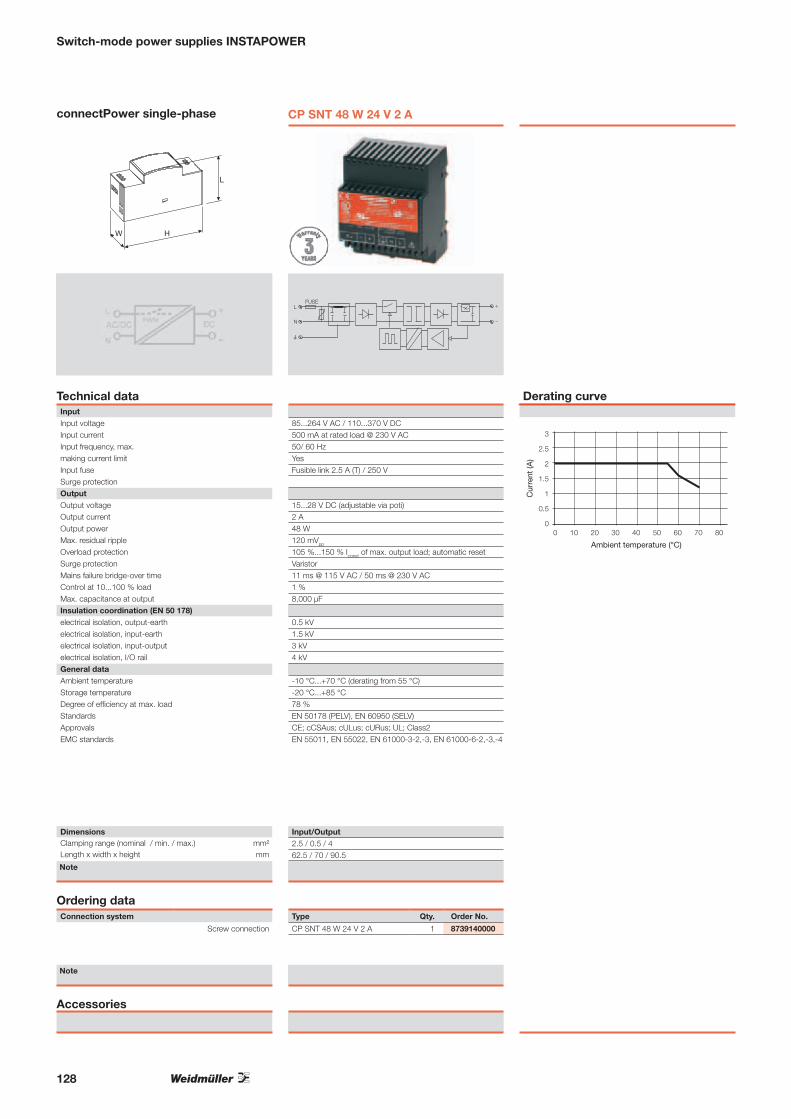
128
Switch-mode power supplies INSTAPOWER
connectPower single-phase
W H
L
Technical dataInputInput voltageInput currentInput frequency, max.making current limitInput fuseSurge protectionOutputOutput voltageOutput currentOutput powerMax. residual rippleOverload protectionSurge protectionMains failure bridge-over timeControl at 10...100 % loadMax. capacitance at outputInsulation coordination (EN 50 178)electrical isolation, output-earthelectrical isolation, input-earthelectrical isolation, input-outputelectrical isolation, I/O railGeneral dataAmbient temperatureStorage temperatureDegree of efficiency at max. loadStandardsApprovalsEMC standards
DimensionsClamping range (nominal / min. / max.) mm²Length x width x height mm
Note
Ordering dataConnection system
Screw connection
Note
Accessories
CP SNT 48 W 24 V 2 A
+FUSE
L
N −
85...264 V AC / 110...370 V DC 500 mA at rated load @ 230 V AC 50/ 60 Hz YesFusible link 2.5 A (T) / 250 V
15...28 V DC (adjustable via poti) 2 A 48 W120 mVpp
105 %...150 % Iconst of max. output load; automatic reset Varistor 11 ms @ 115 V AC / 50 ms @ 230 V AC 1 % 8,000 µF
0.5 kV1.5 kV3 kV4 kV
-10 °C...+70 °C (derating from 55 °C) -20 °C...+85 °C78 %EN 50178 (PELV), EN 60950 (SELV)CE; cCSAus; cULus; cURus; UL; Class2EN 55011, EN 55022, EN 61000-3-2,-3, EN 61000-6-2,-3,-4
Input/Output2.5 / 0.5 / 462.5 / 70 / 90.5
Type Qty. Order No.
CP SNT 48 W 24 V 2 A 1 8739140000
Derating curve
0 10 20 30 40 50 60 70 80
3
2.5
2
1.5
1
0.5
0
Ambient temperature (°C)
Cur
rent
(A)

129
Switch-mode power supplies INSTAPOWER
connectPower single-phase
W H
L
Technical dataInputInput voltageInput currentInput frequency, max.making current limitInput fuseSurge protectionOutputOutput voltageOutput currentOutput powerMax. residual rippleOverload protectionSurge protectionMains failure bridge-over timeControl at 10...100 % loadMax. capacitance at outputInsulation coordination (EN 50 178)electrical isolation, output-earthelectrical isolation, input-earthelectrical isolation, input-outputelectrical isolation, I/O railGeneral dataAmbient temperatureStorage temperatureDegree of efficiency at max. loadStandardsApprovalsEMC standards
DimensionsClamping range (nominal / min. / max.) mm²Length x width x height mm
Note
Ordering dataConnection system
Screw connection
Note
Accessories
CP SNT 48 W 48 V 1 A
+FUSE
L
N −
85...264 V AC / 110...370 V DC 500 mA at rated load @ 230 V AC 50/ 60 Hz YesFusible link 2.5 A (T) / 250 V
46...55 V DC (adjustable via poti) 1 A 48 W120 mVpp
105 %...150 % Iconst of max. output load; automatic reset Varistor 11 ms @ 115 V AC / 50 ms @ 230 V AC 1 % 8,000 µF
0.5 kV1.5 kV3 kV4 kV
-10 °C...+70 °C (derating from 55 °C) -20 °C...+85 °C80 %EN 50178 (PELV), EN 60950 (SELV)CE; cCSAus; cURus; UL; Class2EN 55011, EN 55022, EN 61000-3-2,-3, EN 61000-6-2,-3,-4
Input/Output2.5 / 0.5 / 462.5 / 70 / 90.5
Type Qty. Order No.
CP SNT 48 W 48 V 1 A 1 8879230000
Derating curve
0 10 20 30 40 50 60 70 80
2
1,5
1
0,5
0
Ambient temperature (°C)
Cur
rent
(A)

Marking system for photovoltaic systems
For more than 25 years, the Weidmüller name has stood for innovative and mutually compatible marking and printing systems with all the necessary software and service. As a technological and market leader, we feel it is our duty to move with the times. Our products set standards and play a significant part in helping you to master increasingly complex production processes efficiently and reliably.
The PrintJet PRO is part of this unique concept that unites hardware, software and service that have been developed and synchronised to perfection, offering everything from a single source. All of the elements knit together, offering you all sorts of new options in terms of marking terminals, wires, cables and devices. For big companies or small, the system has just the right modules for your needs and can be fine-tuned to meet specific requirements.
Identification systems
Weidmüller has set new standards in its field with its MultiCard program. With a choice of 180 versions and the ongoing expansion of its portfolio, which already includes labels, shrinkable sleeves and CableLine® markers, it caters for all possible needs. If necessary, we are happy to develop a customised solution for your specific needs too.
Marker
130

Identification systems
The PrintJet PRO is a groundbreaking printer, setting new standards in terms of performance and innovation. Our range of printing systems also includes the THM Plus for shrinkable sleeves and the SMark Laser for printing larger batches quickly and in top quality.
Printer
Import, edit and manage your data with our software package that consists of modules catering for the entire field of application, from the CAD workplace to implementing cabinet components in close cooperation with leading CAE manufacturers.
Software
Service
We are here to help you with your requirements at all times, assisting you with everything from installation to training sessions and a whole host of different solutions such as preprinted markers. We break down barriers and are there for you, wherever you are in the world.
For further information, please ask for our catalogue:
Identification systemsOrder number: 1125590000
7
Iden
tifi
kati
on
ssys
tem
eK
atal
og
201
0/20
11
IdentifikationssystemeKatalog
2010 |2011
7KA
TA
LOG
Bestellnummer:1125580000/01/2010/TMMD
www.weidmueller.com
ÄgyptenArgentinienAserbaidschanAustralienBahrainBelgienBosnien undHerzegowinaBrasilienBulgarienChileChinaCosta RicaDänemarkDeutschlandEcuadorEstlandFinnlandFrankreichGriechenlandGroßbritannienHongkong IndienIndonesienIranIrlandIslandIsraelItalienJapanJordanien
KanadaKasachstanKatarKolumbienKoreaKroatienKuwaitLettlandLibanonLitauenLuxemburgMalaysiaMaltaMazedonienMexikoMoldauNeuseelandNiederlandeNorwegenOmanÖsterreichPakistanPeruPhilippinenPolenPortugalRumänienRusslandSaudi-ArabienSchwedenSchweiz
SerbienSingapurSlowakeiSlowenienSpanienSüdafrikaTaiwanThailandTschechienTunesienTürkeiUkraineUngarnUruguayUsbekistanVenezuelaVereinigteArabischeEmirateVereinigteStaatenVietnamWeißrussland
Weidmüller positioniert sich weltweit erfolgreich unddauerhaft als führender Anbieter von Lösungen fürdie elektrische Verbindung, Übertragung undKonditionierung von Energie, Signalen und Datenim industriellen Umfeld.
Das Unternehmen entwickelt, produziert und vertreibtweltweit Produkte der elektrischen Verbindungstechnikund der Elektronik. Über ein weltweites Netzwerkvon Applikationsspezialisten bietet WeidmüllerEngineering-Dienstleistungen an und entwickeltanwendungsspezifische Lösungen.
Das gesamte Produkt- und Leistungsspektrumsichert unseren Kunden und Weidmüller in gleicherWeise dauerhaft Wettbewerbs- und Wertvorteile.
131

132
Identification systems
The Dekafix marker is the universal marker for terminals andplug-in connectors as well as electronic modules from theWeidmüller product range. Dekafix provides you with a widerange of standard printing options. The system is particularlysuitable for short sequences of numbers and is also availablewith customer specific printing.
• In strips for fast installation• Large selection of ready-to-use printed markers• Excellent printing quality thanks to the MC Laser• Available in 4 widths• Custom printing also possible
Material Polyamide 66, halogen-free
UL 94 flammability rating V2
Temperature range –40 °C to 100 °C
Printing black
DEK card as a terminal marker
Technical data
Colour Available in all colours of the international colour code; for MC
on request
� brown � red � orange
� yellow � green � blue
� violet � grey o white
Qty 500 pcs
Pitch DEK 5 = 5 mm
Printing variations FSZ = consecutive vertical line e.g. DEK 5 FSZ 21-30
GW = identical horizontal e.g. DEK 5 GW A
No. of characters horizontal vertical
DEK 5 max. 3 characters max. 3 characters
Specify colour and characters for special printing
Ordering data
GW
Blank
FWZ
FS
DEK 5 BL NEUTRAL 0473391693DEK 5 BR NEUTRAL 0473391692DEK 5 FSZ 1-10 0460660001DEK 5 FSZ 11-20 0460660011DEK 5 GE NEUTRAL 0473391687DEK 5 GN NEUTRAL 0473391688DEK 5 GR NEUTRAL 0473391691DEK 5 GW 1 0522660001DEK 5 GW 2 0522660002DEK 5 GW 3 0522660003DEK 5 GW 4 0522660004DEK 5 GW 5 0522660005DEK 5 GW 6 0522660006DEK 5 GW 7 0522660007DEK 5 GW 8 0522660008DEK 5 GW 9 0522660009DEK 5 GW 10 0522660010DEK 5 GW 11 0522660011DEK 5 GW 12 0522660012DEK 5 GW 13 0522660013
DEK 5 GW 14 0522660014DEK 5 GW 15 0522660015DEK 5 GW 16 0522660016DEK 5 GW 17 0522660017DEK 5 GW 18 0522660018DEK 5 GW 19 0522660019DEK 5 GW 20 0522660020DEK 5 GW L1 0522361075DEK 5 GW L2 0522361076DEK 5 GW L3 0522361077DEK 5 GW + 0576261198DEK 5 GW - 0576261199DEK 5 GW g 0576261202DEK 5 GW h 0576261203DEK 5 NEUTRAL 0473360000DEK 5 OR NEUTRAL 0473391690DEK 5 RT NEUTRAL 0473391686DEK 5 SW NEUTRAL 0473391694DEK 5 VI NEUTRAL 0473391689
Versions DEKType/Print Order No. Type/Print Order No.

133
Identification systems
Device and installation markers round off the range of switch-gear markers. By utilising Weidmüller’s device markers, userscomply with official regulations requiring marking of electricalequipment. Weidmüller offers corresponding markers fordevices made by well-known manufactures. Mirroring theiroriginal counterparts, these tags are attached with the traditional adhesive or rapid clip-on techniques. By utilising the corresponding software and system-compatible printer or plotter system, users can print their own markings on thesemarkers.
Weidmüller also offers ready-to-use printed labels in the formof a Symbol Packs or Service Packs.
A samples bag containing a selection of device and installationmarkers is available under the order no. 1646370000.
ClipCard as a device marker
Marko Cards are strips of labels printed with a lightning flash. This symbol is available in four differentsizes. For marking electrical equipment, with good resistance to alkyl-alcohols and petrol.
Marko Cards
Technical specificationMaterial Acrylic-coated fibre webbing
Adhesive Permanent acrylic copolymer
Min. temperature, continuous -29 °C
Max. temperature, continuous 80 °C
Material colour yellow
Quantity per pack: 10 sheets
Ordering dataType Length Height Printing No. per sheet Qty Order No.
Marko Card 100 mm 100 mm Lightning flash in triangle 3 10 1700550001
Marko Card 200 mm 200 mm Lightning flash in triangle 1 10 1700560001
Marko Card 25 mm 25 mm Lightning flash in triangle 14 10 1700530001
Marko Card 50 mm 50 mm Lightning flash in triangle 7 10 1700540001
Symbol Pack
Technical specificationMaterial Acrylic-coated fibre webbing
Adhesive Permanent acrylic copolymer
Min. temperature, continuous -45 °C
Max. temperature, continuous 80 °C
Material colour yellow
Quantity per pack: 10 sheets/pack
Symbol Pack is a pocket-sized package with preprinted electrical symbols on perforated sheets. Theperfect solution for marking electrical systems, with good resistance to alkyl-alcohols and petrol.
Ordering dataType Length Height Printing No. per sheet Qty Order No.
Symbol Pack 9 mm 19 mm Symbol 2 54 1 1685700000
Symbol Pack 14 mm 14 mm Symbol 1 48 1 1685690001
Symbol Pack 14 mm 14 mm h 48 1 1685690002
Symbol Pack 25 mm 25 mm Lightning flash in triangle 12 1 1741090000
Symbol Pack 50 mm 50 mm Lightning flash in triangle 4 1 1741100000
Symbol Pack 75 mm 75 mm Lightning flash in triangle 2 1 1741110000

134
Identification systems
The ClipCard device markers in MultiCard format represent an alternative to engraving. The range isused to identify electrical installations and switchgear. Thanks to the established MultiCard format, label-ling with SMark-Laser, PrintJet, Plotter and MC-Mobilo is possible.• Hardwearing printing quality with the PrintJet as a substitute for engraving• Universal fixing• Holder (fixed with screws or cable ties)• Tag rail (self-adhesive or screwed)• Self-adhesive tags
Technical data
Material Polyamide 66, halogen-free
Flammability classification toUL94 V2
Temperature range °C –40 … 100
Temperature range °C –40 … 60 (self-adhesive)
Approved air humidity Max. 60 %, only for screwable tags
Ordering data
Ordering data
Ordering data
ClipCard, blank
ClipCard, blank, self-adhesive
Special print
Qty. Order No.Width x
Type Length (mm) white silver grey red yellow
CC 15/17 MC 15 x 17 80 1876570000 1876610000 1079530000 1131930000
CC 15/27 MC 15 x 27 80 1876770000 1876760000 1079550000 1131940000
CC 15/45 MC 45 x 15 40 1111210000 1111240000 1111230000
CC 15/49 MC 15 x 49 40 1877260000 1877240000 1079570000 1076970000
CC 15/60 MC 15 x 60 40 1877350000 1877340000 1072640000 1131960000
CC 30/60 MC 30 x 60 30 1934420000 1934400000 1072670000 1009320000
CC 85/54 MC 54 x 85 10 1138400000 1138420000 1138410000
Qty. Order No.Width x
Type Length (mm) white silver grey red yellow
CC 15/17 K MC 15 x 17 80 1876590000 1876580000 1079540000 1131920000
CC 15/27 K MC 15 x 27 80 1876640000 1876780000 1079560000 1131910000
CC 15/45 K MC 45 x 15 40 1111250000 1111270000 1111260000
CC 15/49 K MC 15 x 49 40 1877220000 1877270000 1079580000 1131970000
CC 15/60 K MC 15 x 60 40 1877310000 1877360000 1072650000 1131890000
CC 30/60 K MC 30 x 60 30 1934390000 1934330000 1072680000 1085430000 1078320000
CC 85/54 K MC 54 x 85 10 1138430000 1138450000 1138440000
Qty. Order No.Width x
Type Length (mm) Colour and print details
CC 15/17 MC 15 x 17 16 1876620000
CC 15/17 K MC 15 x 17 16 1876600000
CC 15/27 MC 15 x 27 16 1876630000
CC 15/27 K MC 15 x 27 16 1876750000
CC 15/45 MC 45 x 15 8 1111190000
CC 15/45 K MC 45 x 15 8 1111200000
CC 15/49 MC 15 x 49 8 1877200000
CC 15/49 K MC 15 x 49 8 1877230000
CC 15/60 MC 15 x 60 8 1877300000
CC 15/60 K MC 15 x 60 8 1877320000
CC 30/60 MC 30 x 60 6 1934410000
CC 30/60 K MC 30 x 60 6 1934370000
CC 85/54 MC 54 x 85 2 1138460000
CC 85/54 K MC 54 x 85 2 1138470000

135
Identification systems
SlimFix are wire and cable markers featuring a space-savingdesign. The markers can also be attached to the wires afterthese have been installed. They are made from halogen-freematerial and fulfil V0/V2 flammability class requirements. SlimFixis an approved and listed marker for traffic engineering. Attachingeven small markers is no problem when using the SF tool.
• Halogen-free material• V0/V2 flammability class • Approved and listed markers, includes traffic engineering• Attach to conductor cross-sections greater than 16.0 mm2
with cable ties• Markers available in the proven MultiCard format• Also available in flammability class V0. Contact Weidmüller for
more information.SF/SFX
Material Wemid / Polyamide
Flammability class to UL94 V0/V2
Temperature range V0: –5 °C ... 120 °C/V2: –40 °C ... 100 °C
Possible printing systems SMark-Laser, PrintJet, Plotter MCP Plus oder MC-Mobilo
Colour Other colours on reques
� brown � red � orange
� yellow, � green � blue
� violet � grey o white
Notes on mounting SF: Slide onto unconnected wires; attach to
connected wires using SlimFix tool
SFX: Attach using cable ties
Minimum order quantity 1 pack
Special printing Specify special printing and colours per diskette,
Excel file or using the M-Print® PRO software.
SFX 9/24SFX 10/23 SFX 14/23
Halogen
SlimFix to mark cables
Technical data
Ordering data
SFX
SFX S application

136
Identification systems
SF - blank
Technical specification
Material Polyamide 66
UL 94 flammability rating V2
Min. temperature, continuous -40 °C
Max. temperature, continuous 100 °C
SlimFix made from V2 material is a conductor and cable marker system with a space-saving design.The SF V2 made from halogen free material exhibits good mechanical and printing characteristics. Arialis the recommended font when using the PrintJet. The SF tool permits easy installation.• halogen free material • flammability rating V2• SFX attached with cable ties (3.6 mm wide)
Ordering dataType Printing area Length Qty. Order No. Order No. Order No. Order No.
white yellow blue red
SF 00/12 12x3.2 mm 12 400 1919290000 1919260000 1919270000 1919280000
SF 0/12 12x3. 2 mm 12 400 1919240000 1919210000 1919220000 1919230000
SF 1/12 12x3.2 mm 12 400 1919390000 1919340000 1919360000 1919320000
SF 2/12 12x3.6 mm 12 400 1919490000 1919470000 1919480000 1919460000
SF 3/12 12x4.6 mm 12 320 1919540000 1919520000 1919550000 1919530000
SF 4/12 12x5.7 mm 12 128 1919600000 1919580000 1919590000 1919570000
SF 5/12 12x7.4 mm 12 160 1919650000 1919620000 1919630000 1919640000
SF 00/21 21x3.2 mm 21 400 1918580000 1918560000 1918590000 1918570000
SF 0/21 21x3.2 mm 21 400 1918500000 1918480000 1918510000 1918490000
SF 1/21 21x3.2 mm 21 400 1918630000 1918610000 1918620000 1918600000
SF 2/21 21x3.6 mm 21 400 1918690000 1918660000 1918700000 1918670000
SF 3/21 21x4.6 mm 21 320 1918910000 1918890000 1918920000 1918900000
SF 4/21 21x5.7 mm 21 192 1919080000 1919060000 1919090000 1919070000
SF 4,5/21 21x7.4 mm 21 96 1919020000 1919000000 1919030000 1919010000
SF 5/21 21x7.4 mm 21 160 1919140000 1919120000 1919150000 1919130000
SF 6/21 21x8.4 mm 21 160 1919190000 1919170000 1919200000 1919180000
SFX 10/23 23x5 mm 23 160 1852390000 1852360000 1852400000 1852370000
SFX 14/23 23x8.2 mm 23 160 1852440000 1852410000 1852450000 1852420000
SFX 9/24 23.9x9 mm 24 160 1852490000 1852460000 1852500000 1852470000
SFX 11/60 11x44 mm 60 60 1860120000 1860150000 1051870000 1963650000
SFX 30/60* 30x45 mm 60 30 1083230000 1083240000* Order No. for colour grey: 1083250000
SF - Custom printingType Printing area Length Qty. Order No.
SF 00/12 12x3.2 mm 12 80 1919300000
SF 0/12 12x3.2 mm 12 80 1919250000
SF 1/12 12x3.2 mm 12 80 1919420000
SF 2/12 12x3.6 mm 12 80 1919500000
SF 3/12 12x4.6 mm 12 64 1919510000
SF 4/12 12x5.7 mm 12 32 1919610000
SF 5/12 12x7.4 mm 12 32 1919660000
SF 00/21 21x3.2 mm 21 80 1918530000
SF 0/21 21x3.2 mm 21 80 1918470000
SF 1/21 21x3.2 mm 21 80 1918640000
SF 2/21 21x3.6 mm 21 80 1918650000
SF 3/21 21x4.6 mm 21 64 1918880000
SF 4/21 21x5.7 mm 21 48 1919050000
SF 4,5/21 21x7.4 mm 21 32 1918990000
SF 5/21 21x7.4 mm 21 32 1919110000
SF 6/21 21x8.4 mm 21 32 1919160000
SFX 10/23 23x5 mm 23 32 1852380000
SFX 14/23 23x8.2 mm 24 32 1852430000
SFX 9/24 23.9x9 mm 24 32 1852480000
SFX 11/60 11x44 mm 60 12 1860140000
SFX 30/60 30x45 mm 60 30 1083260000
Type Cond. ext. Ø. (max.) mm Cond. cross-section mm2
SFX only: max. width of cable tie = 3.60 mm
Selection table
0.9 / 1.00 – 1.30
1.20 – 1.60
1.70 – 2.10
2.20 – 2.90
3.00 – 3.70
3.60 – 6.00
4.10 – 4.90
4.80 – 7.40
5.80 – 7.80
from 7.00
SF 00
SF 0
SF 1
SF 2
SF 3
SF 4
SF 4.5
SF 5
SF 6
SFX
< 0.25
0.25 – 0.50
0.50 – 0.75
0.75 – 1.50
1.50 – 2.50
2.50 – 4.00
4.00 – 6.00
6.00 – 10.00
10.00 – 16.00
from 16.00

137
Identification systems
The special profile of the TM-I results in easy installation andsecure marking. TM-I tags are compatible with many of thesleeves available on the market. Their MultiCard format meansquick and convenient printing with the SMark-Laser, PrintJet,MCP Plus Plotter, MC-Mobilo or STI-S pen systems. Thanks tothe project name panels on the MultiCards, the tags are easyto separate and mount. TM-I is an acknowledged and accred-ited marker for traffic engineering applications. Five differenttag lengths are available for individual labelling with long character strings.
• Easily separated and mounted thanks to the project namepanels
• Acknowledged and accredited marker for traffic engineering• Fitting the sleeves first and inserting the labels later adds up
to maximum flexibility• Not suited for labelling with P-Ink or STI-S pen in connection
with CLI T sleeves
Material Polyamide 66, halogen-free
UL 94 flammability rating V2
Temperature range –40 °C to 100 °C
Printing black
Ordering data
Colour Other colours on request
� brown � red � orange
� yellow � green � blue
� violet � grey o white
Special printing Specify special printing and colours per diskette, Excel file or
using the M-Print® PRO software.
Minimum order quantity 1 pack
TM-I top to mark cables
Technical data
Halogen

138
Halogen
TM/HF - sleeve
Technical specificationMaterial Polyethylene LD
UL 94 flammability rating HB
Min. temperature, continuous -20 °C
Max. temperature, continuous 80 °C
Material colour transparent
The TM/HF sleeve is free from halogens and essentially free from other hazardous substances. Thesleeves are fitted with the TM-I 12 or TM-I 18. They are suitable for a wide range of cables and conduc-tors. This system has proved particularly beneficial in transport engineering. The slim design guaranteesa firm attachment to the cable.• halogen free,• slim design guarantees firm attachment to cable.• TMX 18 fixed with cable ties (3.6 mm wide)
Ordering dataType Length Insulation O.D. Cond. cross-section Qty Order No.
TM 0/12 HF/HB 12 mm 1.3-2.0 mm 0.22-0.5 mm2 1,000 1719760000
TM 0/18 HF/HB 18 mm 1.3-2.0 mm 0.22-0.5 mm2 1,000 1719770000
TM 1/12 HF/HB 12 mm 1.8-2.5 mm 0.5-1.5 mm2 1,000 1719780000
TM 1/18 HF/HB 18 mm 1.8-2.5 mm 0.5-1.5 mm2 1,000 1719790000
TM 2/12 HF/HB 12 mm 2.5-4.0 mm 0.75-2.5 mm2 1,000 1719800000
TM 2/18 HF/HB 18 mm 2.5-4.0 mm 0.75-2.5 mm2 1,000 1719810000
TM 3/12 HF/HB 12 mm 4.0-6.5 mm 2.5-6 mm2 500 1719820000
TM 3/18 HF/HB 18 mm 4.0-6.5 mm 2.5-6 mm2 500 1719830000
TM 4/12 HF/HB 12 mm 6.0-10.0 mm 10-35 mm2 500 1719840000
TM 4/18 HF/HB 18 mm 6.0-10.0 mm 10-35 mm2 500 1719850000
TM 5/12 HF/HB 12 mm 9.0-15.0 mm 25-70 mm2 200 1719860000
TM 5/18 HF/HB 18 mm 9.0-15.0 mm 25-70 mm2 200 1719870000
TM 6/12 HF/HB 12 mm 15.0-24.0 mm 35-150 mm2 200 1719880000
TM 6/18 HF/HB 18 mm 15.0-24.0 mm 35-150 mm2 200 1719890000
TMX 18 HF/HB 18 mm 10.0-317.0 mm 16-150 mm2 500 1748820000
Identification systems
Halogen
TM-I blank
Technical specificationMaterial Polyamide 66
UL 94 flammability rating V2
Min. temperature, continuous -40 °C
Max. temperature, continuous 100 °C
Ordering dataType Length Width Material colour Qty Order No.
TM-I 12 BLANK WS 12 mm 4 mm white 320 1718411044
TM-I 12 BLANK GE 12 mm 4 mm yellow 320 1718411687
TM-I 12 BLANK BL 12 mm 4 mm Blue 320 1718411693
TM-I 12 BLANK RT 12 mm 4 mm red 320 1718411686
TM-I 12 BLANK GN 12 mm 4 mm green 320 1718411688
TM-I 18 BLANK WS 18 mm 4 mm white 320 1718431044
TM-I 18 BLANK GE 18 mm 4 mm yellow 320 1718431687
TM-I 18 BLANK BL 18 mm 4 mm Blue 320 1718431693
TM-I 18 BLANK RT 18 mm 4 mm red 320 1718431686
TM-I 18 BLANK GN 18 mm 4 mm green 320 1718431688
TM-I Custom printing
Technical specificationMaterial Polyamide 66
UL 94 flammability rating V2
Min. temperature, continuous -40 °C
Max. temperature, continuous 100 °C
Material colour To customer specification
Type Length Width Qty Order No.
TM-I 12 CUSTOM PRINT 12 mm 4 mm 64 1718420000
TM-I 18 CUSTOM PRINT 18 mm 4 mm 64 1718440000

Identification systems
The PrintJet PRO inkjet printer prints markers for electric connectivity. These markers can be used for clear equipment identification on devices, cables and connectors. The labelling makes servicing, maintenance and troubleshooting much easier. Water-based ink is used for the black or spot colour printing. The print is crystal clear and resistant to environmental influences. The PrintJet PRO prints plastic markers in MultiCard format. In combination with the user-friendly M-Print® PRO software and the attached loader, the printer becomes an essential part of the production.The inkjet process being used, the subsequent fusing, as well as the printer cartridge and ink have all been specially adapted by Weidmüller for industrial use. The printer has excellent long-term use capabilities, thanks to its integrated loader.
• Top-quality, resistant printing
• Spot colour print
• Perfect for constant use
• Integrated loader for 20 MultiCards
• Ideal for large quantities
• The display shows all relevant information
• Flexible connection options, from LAN ports to USB ports
PrintJet PRO
Technical dataPrintJet PROType PrintJet PRO
Application Prints MultiCard markers
Technology Inkjet process
Print quality 600 / 1.200 dpi
Printer drivers Windows® 2000/XP/VISTA
Print software M-Print® PRO
System requirements Windows® 2000/XP/VISTA
Feed Integrated loader
Fusing Thermal fusing
Interface USB, LAN
Power supply AC 230 V or AC 115 V
Location Office conditions
Ambient temperature 20° to 35 °C
Dimensions (L x W x H) 1,060 x 500 x 310 mm
Weight 33 kg
Cartridge system Ink cartridge, CMYK (1,000,000 characters, Arial font size 6)
Scope of supply PrintJet printer, power cable, printer drivers, manuals (CD),
USB cable, M-Print® PRO software
Ordering data PrintJet PROType Order No.PrintJet PRO 115V 1024050000
PrintJet PRO 230V 1001180001AccessoriesPJ PRO TNTK INK SET COL Ink tank starter set, colour 1027110000
PJ PRO TNTK INK K l Ink tank Black 1027040000
PJ PRO TNTK INK C l Ink tank Cyan 1027050000
PJ PRO TNTK INK M l Ink tank Magenta 1027060000
PJ PRO TNTK INK Y l Ink tank Yellow 1027070000
PJ PRO TNAW waste pad 1024140000
139

Identification systems
Technical data
Here is an overview of the main functionsIntegrated product catalogue for all labels and markers, including images and links to the relevant web pages and product data sheets
Custom formatting of individual text characters (RTF)
Perform copy-and-paste functions with texts and their formats
Supports UNICODE for foreign-language texts, such as Russian, Chinese, Polish, etc.
Enter data on labels or worksheet
Numeric and alphanumeric counts and sequences
Extensive range of image formats (*.bmp, *.wmf, *.png, *.ico, *.jpeg, *.tif, *.gif)
Image library including all the important symbols used in electrical engineering
Permanent print preview: see how the printout will look during the design phase
Output devices supported: PrintJet PRO, PrintJet I+II, SMark-Laser, ThermoCard, THM
as well as standard printers with Win dows® drivers, plotter MCP
Assign product to specific printer; for example, ESG 9/20 to PrintJet, LaserMark to laser printer, etc.
Optimum and rapid adjustment of the output devices
Imports data from CAE systems
Import assistant to create your own import filter for numerous file formats (*.txt, *.csv, *.xml etc.)
Markers and labels can be designed in as many levels as required
Interface to RailDesigner®
Operating systems supportedWINDOWS® 2000/XP/VISTA/7
System requirementsRAM > 256 MB
Processor > Pentium PIII or comparable model
Grafik > 800 x 600 pixels with 256 colours
optimum: 1024 x 768 with 16-bit High Colour
Hard drive > 90 MB free storage
Miscellaneous mouse, keyboard, CD-ROM drive (to install the software)
M-Print® PRO is available in two editions:• M-Print® PRO Standard Edition for professional printing results with all of Weidmüller’s marking materials• M-Print® PRO Advanced Edition for professional printing results with all of Weidmüller’s marking materials plus labels to customer specification
Ordering data M-Print® PROType Order No.M-Print® PRO 1905490000
M-Print® PRO advanced 1905500000
Print and ordering software for markers and labels
M-Print® PRO is a professional software for printing and ordering Weidmüller markers and labels under Windows®. This software helps you to optimise your processes for marking electrical equipment. You can design, print and order your marking materials effortlessly, professionally and quickly: texts, frames, lines, graphics, barcodes, serial numbers and photos.
M-Print® PRO Label Designer
140

141

Professional tools for installation
Professional tools for installation
Practical tools for mounting combiner boxes
Weidmüller has been developing and manufacturing quality tools for demanding needs for more than 30 years. We always have our sights set on a single goal when developing new solutions: namely to make your work easier, facilitate smooth work processes and to secure your company’s productivity in the long term.
The KT 45 R has a lot going for it: an extremely narrow grip width, energy-efficient operation, cuts up to 400 mm2 and an easy release option even under load.
Cutting tool
The advantage of the AM 25 and AM 35 sheathing strippers for PVC round cables: a rotatable knife for precise circular, lengthwise and spiral cuts on cables with diameters of up to 35 mm.
Sheath stripper
The AM 16 sheathing stripper allows you to remove a section of sheathing in the middle of a cable too, in order to generate equipotential bonding for achieving electromagnetic compatibility with a clamping yoke.
Sheath stripper
You can achieve precise stripping results ranging from 0.08 to 10 mm2 with the stripax® selfdjusting stripping tool. The perfect addition: stripax® 16, 6 to 16 mm2, with a special blade form.
Stripping tool
142

Professional tools for installation
You can use the CTN series to crimp cable lugs ranging from 10 to 25 mm2 with just one hand and in accordance with the DIN 46234 and DIN 46235 standards.
Crimping tool
The rotating die of the PZ 6 roto means that wire end ferrules can be inserted from the front or the side. Highest processing quality is guaranteed with a single die of 0.14 to 6 mm2.
Crimping tool
The specially designed cutters on our KT tools result in smooth and straight cuts every time, without deforming the conductor.
Cutting tool
With this tool, you will always be within the correct torque range. It guarantees safe and gas-tight connections, prevents the screw clamps from being mechanically damaged, and results in a voltage drop well below the stipulated limits.
Torque screwdriver
For further information, please ask for our catalogue:
ToolsOrder number: 1161520000
6
Wer
kzeu
ge
Kat
alo
g 2
010/
2011
WerkzeugeKatalog
2010 |2011
6KA
TA
LOG
Bestellnummer:1161510000/02/2010/TMMD
www.weidmueller.com
ÄgyptenArgentinienAserbaidschanAustralienBahrainBelgienBosnien undHerzegowinaBrasilienBulgarienChileChinaCosta RicaDänemarkDeutschlandEcuadorEstlandFinnlandFrankreichGriechenlandGroßbritannienHongkong IndienIndonesienIranIrlandIslandIsraelItalienJapanJordanien
KanadaKasachstanKatarKolumbienKoreaKroatienKuwaitLettlandLibanonLitauenLuxemburgMalaysiaMaltaMazedonienMexikoMoldauNeuseelandNiederlandeNorwegenOmanÖsterreichPakistanPeruPhilippinenPolenPortugalRumänienRusslandSaudi-ArabienSchwedenSchweiz
SerbienSingapurSlowakeiSlowenienSpanienSüdafrikaTaiwanThailandTschechienTunesienTürkeiUkraineUngarnUruguayUsbekistanVenezuelaVereinigteArabischeEmirateVereinigteStaatenVietnamWeißrussland
Weidmüller positioniert sich weltweit erfolgreich unddauerhaft als führender Anbieter von Lösungen fürdie elektrische Verbindung, Übertragung undKonditionierung von Energie, Signalen und Datenim industriellen Umfeld.
Das Unternehmen entwickelt, produziert und vertreibtweltweit Produkte der elektrischen Verbindungstechnikund der Elektronik. Über ein weltweites Netzwerkvon Applikationsspezialisten bietet WeidmüllerEngineering-Dienstleistungen an und entwickeltanwendungsspezifische Lösungen.
Das gesamte Produkt- und Leistungsspektrumsichert unseren Kunden und Weidmüller in gleicherWeise dauerhaft Wettbewerbs- und Wertvorteile.
143

Cutting tools
Cutting tools
Technical data
• Cutting formation for different cable sizes increases the quality of the cuts for smaller cross-sections
• Not suitable for steel wires, steel-armoured cables, aluminium alloys and hard-drawn copper conductors!
• Cutting without deformation of the conductor
Max. cutting performance, copper cableSolid (max. conductor cross-section) mm²/AWGStranded (max. conductor cross-section) mm²/AWGFlexible (max. conductor cross-section) mm²/AWGFlexible, stranded (max. conductor diameter) mmMax. cutting performance, aluminium cableStranded (max. conductor cross-section) mm²/-Stranded (max. conductor diameter) mmsolid mm²Data / telephone / control cableMax. outer diameter mmTool dataLength / Width / Height mmWeight g
Note
max. 8 mm
max. 16 mm2
max. 16 mm2
max. 16 mm2
Version
Note
KT 8 KT 12
Tool closed
Type Qty. Order No.
KT 8 1 9002650000
KT 12 1 9002660000
Ordering data
KT8 KT1216 / 6 16 / 616 / 6 25 / 316 / 6 35 / 28 12
16 / 6 25 / 68 816 25
8 12
165 / 65 / 25 215 / 66 / 28180 300
KT 22
max. 22 mm
max. 25 mm2
max. 50 mm2
max. 95 mm2
max. 12 mm
max. 16 mm2
max. 25 mm2
max. 35 mm2
KT2225 / 350 / 195 / 3/022
70 / 2/02250
22
220 / 66 / 30460Tool closed
Type Qty. Order No.
KT 22 1 1157830000
144

Cutting tools
Cutting tools
Technical data
• Easy handling because of automatic opening• Safety lock reduces risk of injury• Not suitable for steel wires, steel-armoured
cables, aluminium alloys and hard-drawn copper conductors!
Max. cutting performance, copper cableSolid (max. conductor cross-section) mm²/AWGStranded (max. conductor cross-section) mm²/AWGFlexible (max. conductor cross-section) mm²/AWGFlexible, stranded (max. conductor diameter) mmMax. cutting performance, aluminium cableStranded (max. conductor cross-section) mm²/-Stranded (max. conductor diameter) mmsolid mm²Data / telephone / control cableMax. outer diameter mmTool dataLength / Width / Height mmWeight g
Note
Version
Note
Ordering data
max. 14 mm
max. 16 mm2
max. 35 mm2
max. 70 mm2
KT 14
Tool closed
Type Qty. Order No.
KT 14 1 1157820000
Specifying „solid-core aluminium cable“ corresponds to sector-shaped conductor with individual strands
KT1416 / 635 / 270 / 2/014
70 / 2/01435
14
215 / 66 / 28320
max. 20 mm
max. 16 mm2
max. 35 mm2
max. 70 mm2
KT 20
Tool closed
Type Qty. Order No.
KT 20 1 9002300000
Specifying „solid-core aluminium cable“ corresponds to sector-shaped conductor with individual strands
KT2016 / 635 / 270 / 2/020
70 / 2/02035
20
215 / 66 / 29400
145
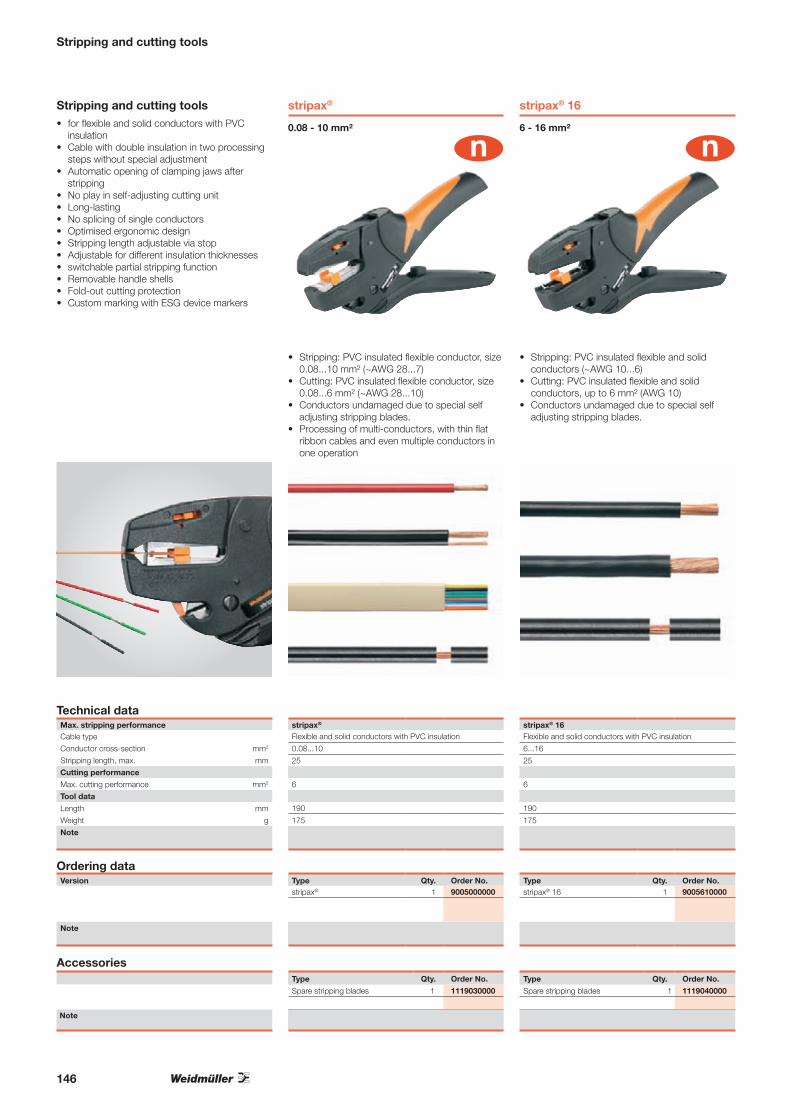
Stripping and cutting tools
Note
Type Qty. Order No.
Spare stripping blades 1 1119030000
AccessoriesType Qty. Order No.
Spare stripping blades 1 1119040000
Stripping and cutting tools• for flexible and solid conductors with PVC
insulation• Cable with double insulation in two processing
steps without special adjustment• Automatic opening of clamping jaws after
stripping• No play in self-adjusting cutting unit• Long-lasting• No splicing of single conductors• Optimised ergonomic design• Stripping length adjustable via stop• Adjustable for different insulation thicknesses• switchable partial stripping function• Removable handle shells• Fold-out cutting protection• Custom marking with ESG device markers
Technical dataMax. stripping performanceCable type
Conductor cross-section mm2
Stripping length, max. mm
Cutting performance
Max. cutting performance mm2
Tool data
Length mm
Weight g
Note
Ordering dataVersion
Note
stripax®
0.08 - 10 mm²
stripax® 16
6 - 16 mm²
stripax®
Flexible and solid conductors with PVC insulation
0.08...10
25
6
190
175
Type Qty. Order No.stripax® 1 9005000000
stripax® 16Flexible and solid conductors with PVC insulation
6...16
25
6
190
175
Type Qty. Order No.stripax® 16 1 9005610000
• Stripping: PVC insulated flexible conductor, size 0.08...10 mm² (~AWG 28...7)
• Cutting: PVC insulated flexible conductor, size 0.08...6 mm² (~AWG 28...10)
• Conductors undamaged due to special self adjusting stripping blades.
• Processing of multi-conductors, with thin flat ribbon cables and even multiple conductors in one operation
• Stripping: PVC insulated flexible and solid conductors (~AWG 10...6)
• Cutting: PVC insulated flexible and solid conductors, up to 6 mm² (AWG 10)
• Conductors undamaged due to special self adjusting stripping blades.
146

Stripping tools
Sheathing strippers
Technical data
• Sheathing stripper for PVC cables• Insulation can be stripped from any point along
the cable• Opening of slit insulation by means of integrated
cutter
Max. stripping performanceCable typeConductor cross-section -Conductor diameter mmDepth of cutCutting performanceUTP und STP data cables, max. diameter mmFlexible (max. conductor cross-section) mm²Tool dataLength mmWeight g
Note
Version
Note
Note
For round cable, Ø 6...17 mm
AM 16
Type Qty. Order No.
AM 16 1 9204190000
Type Qty. Order No.
Spare blade 1 9204260000Sheathing stripper
Ordering data
AM 16PVC round cable
6...170.8 - 2.5 mm
5360
Accessories
• Especially suitable for stripping cables in the cable duct, too
AMF 6/10
For ribbon cable, 6 mm² and 10 mm²
AMF 6/10PVC ribbon cable
0 - 4.0 mm
110115
Type Qty. Order No.
AMF 6/10 1 9204180000
Type Qty. Order No.
Spare blade 1 9204250000Sheathing stripper
147

Crimping tools for wire end ferrules
Crimping tools for wire end ferrules
Technical data
• For wire-end ferrules with and without plastic collars, according to DIN 46228 T.1 and T.4 (~ AWG 24...16)
• Ratchet for precise crimping.• Release option in the event of incorrect
operation
Description of contactType of contactCrimping range mm²Crimping range 1 (with multiple crimping positions) mm²Crimping range 2 (with multiple crimping positions) mm²Crimping range 3 (with multiple crimping positions) mm²Crimping range 4 (with multiple crimping positions) mm²Crimping range 5 (with multiple crimping positions) mm²Tool dataLength mmWeight g
Note
Version
Note
0.5...6 mm²
PZ 3
Type Qty. Order No.
PZ 3 1 0567300000
Ordering data
PZ 3Wire-end ferrules with/without plastic collars0.5...6
200426
• Only one die for the whole cross-section range• Wire-end ferrule insertion from the front
PZ 6 roto
0.14...6 mm²
• Only one die for the whole cross-section range• Rotating die enables wire-end ferrule insertion
from the front or side
PZ 6 RotoWire-end ferrules with/without plastic collars0.14...6
200428
Type Qty. Order No.
PZ 6 Roto 1 9014350000
148

Crimping tools for wire end ferrules
Crimping tools for wire end ferrules
Technical data
• For wire-end ferrules with and without plastic collars, according to DIN 46228 T.1 and T.4 (~ AWG 24...16)
• Ratchet for precise crimping.• Release option in the event of incorrect
operation
Description of contactType of contactCrimping range mm²Crimping range 1 (with multiple crimping positions) mm²Crimping range 2 (with multiple crimping positions) mm²Crimping range 3 (with multiple crimping positions) mm²Crimping range 4 (with multiple crimping positions) mm²Crimping range 5 (with multiple crimping positions) mm²Tool dataLength mmWeight g
Note
Version
Note
6...16 mm²
PZ 16
Type Qty. Order No.
PZ 16 1 9012600000
Ordering data
PZ 16Wire-end ferrules with/without plastic collars6...1661016
200418
• Crimp complies with Euro-Norm EN 60947-1• Approval according to VG 95211 (military
designation VG 95 236 T 14 B 002)• Three crimping stations corresponding to the
conductor cross-sections• Wire-end ferrule insertion from the side
PZ ZH 16
Twin wire-end ferrules from 6...16 mm²
• Three crimping stations corresponding to the conductor cross-sections
• Wire-end ferrule insertion from the side
PZ ZH 16Twin wire-end ferrules6...1661016
250730
Type Qty. Order No.
PZ ZH 16 1 9013600000
149
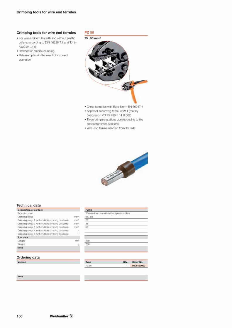
Crimping tools for wire end ferrules
Crimping tools for wire end ferrules
Technical data
• For wire-end ferrules with and without plastic collars, according to DIN 46228 T.1 and T.4 (~ AWG 24...16)
• Ratchet for precise crimping.• Release option in the event of incorrect
operation
Description of contactType of contactCrimping range mm²Crimping range 1 (with multiple crimping positions) mm²Crimping range 2 (with multiple crimping positions) mm²Crimping range 3 (with multiple crimping positions) mm²Crimping range 4 (with multiple crimping positions) -Crimping range 5 (with multiple crimping positions) -Tool dataLength mmWeight g
Note
Version
Note
25...50 mm²
PZ 50
Type Qty. Order No.
PZ 50 1 9006450000
Ordering data
PZ 50Wire-end ferrules with/without plastic collars25...50253550
250730
• Crimp complies with Euro-Norm EN 60947-1• Approval according to VG 95211 (military
designation VG 95 236 T 14 B 002)• Three crimping stations corresponding to the
conductor cross-sections• Wire-end ferrule insertion from the side
150

Crimping tools for other contacts
Crimping tools for other contacts
Technical data
• Ratchet for precise crimping.• Release option in the event of incorrect
operation• With stop for exact positioning of the contacts.• Tested according to DIN EN 60352 part 2
Description of contactType of contactCrimping range mm²Crimping range 1 (with multiple crimping positions) mm²Crimping range 2 (with multiple crimping positions) mm²Crimping range 3 (with multiple crimping positions) mm²Plug width -Tool dataLength mmWeight g
Note
Version
Note
0.5...2.5 mm²
HTI 15
Type Qty. Order No.
HTI 15 1 9014400000
Ordering data
HTI 15Insulated connector0.5...2.50.5...1.51.1...2.5
200434
For PVC, PC, and polyamide insulated connectors0.5...2.5 mm²(~AWG 20 ... AWG 14)
• Double-crimp profile, for crimping contact and insulation in one step
HTN 21
0.5...6 mm²
For uninsulated cable lugs and connectors0.5...6 mm²(AWG 20...10)
• Rolled cable lugs, for example acc. to DIN 46234
• Tubular cable lugs• Pin cable lugs• Parallel and serial connectors• Indent crimp• Alternatively available with or without
pivoting end stop
HTN 21 HTN 21 M. ANUninsulated connection Uninsulated connection0.5...6 0.5...60.5...1.5 0.5...1.51.1...2.5 1.1...2.52.6...6 2.6...6
200 200427 427End stop for secure contact positioning in tool
Type Qty. Order No.
HTN 21 1 9014610000
HTN 21 with pivoting end stop 1 9014100000
151

Crimping tools for other contacts
Crimping tools for other contacts
Technical data
• Ratchet for precise crimping.• Release option in the event of incorrect
operation• With stop for exact positioning of the contacts.
Description of contactType of contactCrimping range mm²Crimping range 1 (with multiple crimping positions) mm²Crimping range 2 (with multiple crimping positions) mm²Crimping range 3 (with multiple crimping positions) mm²Plug width -Tool dataLength mmWeight g
Note
Version
Note
0,5...6 mm²
CTI 6 G
Type Qty. Order No.
CTI 6 G 1 9202850000
Ordering data
CTI 6 GInsulated connector0.5...60.5...1.51.1...2.52.6...6
250747
For PVC, PC, and polyamide insulated connectors0.5...6 mm² (~AWG 20 ... AWG 10)
• Parallel-crimp profile, for crimping contact and insulation in one step
CTI 6
0,5...6 mm²
For PVC, PC, and polyamide insulated connectors0.5...6 mm² (~AWG 20 ... AWG 10)
• Double-crimp profile, for crimping contact and insulation in one step
CTI 6Insulated connector0.5...60.5...1.51.1...2.52.6...6
250730
Type Qty. Order No.
CTI 6 1 9006120000
152

Crimping tools for other contacts
Crimping tools for other contacts
Technical data
• Ratchet for precise crimping.• Release option in the event of incorrect
operation
Description of contactType of contactCrimping range mm²Crimping range 1 (with multiple crimping positions) mm²Crimping range 2 (with multiple crimping positions) mm²Crimping range 3 (with multiple crimping positions) mm²Plug width -Tool dataLength mmWeight g
Note
Version
Note
10...25 mm²
CTN 25 D 4
Type Qty. Order No.
CTN 25 D4 1 9006220000
For rolled cable lugs
Ordering data
CTN 25 D4Uninsulated connection10...25101625
250730
For uninsulated cable lugs and connectors
10...25 mm²
• Rolled cable lugs, acc. to DIN 46234• Pin cable lugs• Parallel and serial connectors• Indent crimp form
CTN 25 D 5
10...25 mm²
For uninsulated cable lugs and connectors
10...25 mm²
• Rolled cable lugs, acc. to DIN 46235• Pin cable lugs• Parallel and serial connectors• Hexagon crimp form
CTN 25 D5Uninsulated connection10...25101625
250730
Type Qty. Order No.
CTN 25 D5 1 9006230000
For tubular cable lugs
153

VDE-insulated torque screwdriver
DMSI manualDMSI MANUAL 0.5-1.7 0.5 - 1.7 Nm 9918390000
DMSI MANUAL 2.0-8.0 2.0 - 8.0 Nm 9918400000VDE-insulated torque screwdriver EN ISO 6798, BS EN 26789, ASME B107.14M
Type Size / AF a b c Order No.
VDE-insulated torque screwdriver
WK SIVDE-insulated interchangeable bits for VDE-insulated torque screwdriver; output acc. to DIN 5264, ISO 2380/1
WK SI 0,4x2,5 Max. 0.4 Nm 0.4 2.5 220 9918410000
WK SI 0,5x3,0 Max. 0.6 Nm 0.5 3.0 220 9918420000
WK SI 0,6x3,5 Max. 1.1 Nm 0.6 3.5 220 9918430000
WK SI 0,8x4,0 Max. 2.5 Nm 0.8 4.0 220 9918440000
WK SI 1,0x5,5 Max. 3.8 Nm 1.0 5.5 220 9918450000
WK IK PHVDE-insulated interchangeable bits for VDE-insulated torque screwdriver; output acc. to DIN 5260-PH, ISO 8764/1-PH
WK IK PH0 Max. 9 Nm 220 9918460000
WK IK PH1 Max. 3.8 Nm 220 9918470000
WK IK PH2 Max. 5.5 Nm 220 9918480000
WK IK PZVDE-insulated interchangeable bits for VDE-insulated torque screwdriver; output acc. to DIN 5260-PZ, ISO 8764/1-PZ
WK IK PZ0 Max. 9 Nm 220 9918490000
WK IK PZ1 Max. 3.8 Nm 220 9918500000
WK IK PZ2 Max. 5.5 Nm 220 9918510000
154

VDE-insulated screwdriver
SDI SSDI 0.4X2.0X60 A 0.4 2.0 60 9205690000
SDI 0,4x2,5x75 A 0.4 2.5 75 9008370000
SDI 0,5x3,0x100 B 0.5 3.0 100 9008380000
SDI 0,6x3,5x100 B 0.6 3.5 100 9008390000
SDI 0,8x4,0x100 B 0.8 4.0 100 9008400000
SDI 1,0x4,5x125 B 1.0 4.5 125 9008910000
SDI 1.0X4.5X175 B 1.0 4.5 175 9205700000
SDI 1,0x5,5x125 B 1.0 5.5 125 9008410000
SDI 1.0X5.5X175 B 1.0 5.5 175 9205710000
SDI 1,2x6,5x150 B 1.2 6.5 150 9008420000
SDI 1,6x8,0x175 B 1.6 8.0 175 9008430000
Type Blade type Size / AF a b c Order No.
SDIK PHSDIK PH0 0 60 9008560000
SDIK PH1 1 80 9008570000
SDIK PH2 2 100 9008580000
SDIK PH3 3 150 9008590000
SDIK PZSDIK PZ1 1 80 9008900000
SDIK PZ2 2 100 9008890000
SDIZSDIZ 0.6X3.5X100 0.6 3.5 100 9008450000
SDIZ 0.8X4.0X100 0.8 4.0 100 9008460000
SDIZ 0.8X5.5 150/248 9008640000
VDE insulated slot-head screwdriver, SDI DIN 7437, ISO 2380/2, drive output acc. to DIN 5264, ISO 2380/1. SoftFinish grip
VDE-insulated screwdriver with pilot tip, for working on live parts up to 1,000 V AC and 1,500 V DC, DIN EN 60900, IEC 900, Safety tested „GS“, each piece tested. Bit made from fully hardened, high-alloy chromium-vanadium-molybdenum steel, gun-metal finish.
VDE-insulated screwdriver, for working on live parts up to 1,000 V AC and 1,500 V DC. DIN EN 60900, IEC 900, Safety tested „GS“, each piece tested. Bit made from fully hardened, high-alloy chromium-vanadium-molybdenum steel, gun-metal finish.
VDE insulated slot-head screwdriver, SDI DIN 7437, ISO 2380/2, drive output acc. to DIN 5264, ISO 2380/1. SoftFinish grip
VDE-insulated screwdriver
VDE-insulated crosshead screwdriver, Phillips type, SDIK PH DIN 7438, ISO 8764/2-PH, output acc. to ISO 8764-PH, SoftFinish grip
VDE-insulated crosshead screwdriver Pozidrive type, SDIK PZ DIN 7438, ISO 8764/2-PZ, output acc. to ISO 8764-PZ, SoftFinish grip
155

Screwdriver SlimLine
VDE-insulated screwdriver SlimLine
VDE-insulated screwdriver, for working on live parts up to 1,000 V AC and 1,500 V DC. DIN EN 60900, IEC 900, Safety tested „GS“, each piece tested. Bit made from fully hardened, high-alloy chromium-vanadium-molybdenum steel, gun-metal finish.
A blade that is up to 33 % thinnerThe SlimLine design allows you to reach deeply inset fittings and tension clamp terminals.
SDI SL SSDI SL 0.6x3.5x100 B 0.6 3.5 100 1274660000
SDI SL 0.8x4.0x100 B 0.8 4.0 100 1274670000
SDI SL 1.0x4.5x125 B 1.0 4.5 125 1274680000
SDI SL 1.2x6.5x150 B 1.2 6.5 150 1274690000
VDE insulated slot-head screwdriver, SDI SL DIN 7437, ISO 2380/2, drive output acc. to DIN 5264, ISO 2380/1. SoftFinish grip
Type Blade type Size / AF a b c Order No.
SDIK SL PHVDE-insulated crosshead screwdriver, Phillips type, SDIK SL PHDIN 7438, ISO 8764/2-PH, output acc. to ISO 8764-PH, SoftFinish grip
SDIK SL PH1 1 80 1274710000
SDIK SL PH2 2 100 1274720000
SDIK SL PZVDE-insulated crosshead screwdriver Pozidrive type, SDIK SL PZDIN 7438, ISO 8764/2-PZ, output acc. to ISO 8764-PZ, SoftFinish grip
SDIK SL PZ1 1 80 1274730000
SDIK SL PZ2 2 100 1274740000
SDIS SL 2.5-5.5/PH/1/2SDI SL 0.6x3.5x100 B 0.6 3.5 100
SDI SL 0.8x4.0x100 B 0.8 4.0 100
SDI SL 1.0x5.5x125 B 1.0 4.5 125
SDI SL 1.2x6.5x150 B 1.2 6.5 150
SDIK SL PH1 1 80
SDIK SL PH2 2 100
SDIS SL 2.5-5.5/PH1/2 1274750000
6-part set: VDE insulated slotted and crosshead PH screwdriver set
156

VDE-insulated screwdriver
SDIS 2.5-5.5/PH/1/26-part set: VDE insulated slotted and crosshead PH screwdriver set SDI 0,4x2,5x75 0.4 2.5 80
SDI 0,5x3,0x100 0.5 3.0 100
SDI 0,8x4,0x100 0.8 4.0 100
SDI 1,0x5,5x125 1.0 5.5 125
SDI PH 1 1 80
SDI PH 2 2 100
SDIS 2,5-5,5/PH1/2 9009730000
Type Blade type Size / AF a b c Order No.
Weidmüller SoftFinish VDE-insulated electric screwdriver for working on live components with up to 1,000 V AC and 1,500 V DC, DIN EN 60900, IEC 900. Safety tested „GS“; each product tested.
SDIS 2.0-5.5SDI 0,4x2,0x60 A 0.4 2.0 60
SDI 0,4x2,5x75 A 0.4 2.5 75
SDI 0,5x3,0x100 B 0.5 3.0 100
SDI 0,6x3,5x100 B 0.6 3.5 100
SDI 0,8x4,0x100 B 0.8 4.0 100
SDI 1,0x5,5x125 B 1.0 5.5 125
SDIS 2.0-5.5 9205550000
VDE insulated slot-head screwdriver, SDI DIN 7437, ISO 2380/2, drive output acc. to DIN 5264, ISO 2380/1. SoftFinish grip
SDIS 2.5-5.5/PZ/1/2Six-piece set: VDE-insulated slotted and PZ-crosshead screwdriver set
SDI 0,4x2,5x75 A 0.4 2.5 80
SDI 0,5x3,0x100 B 0.5 3.0 100
SDI 0,8x4,0x100 B 0.8 4.0 100
SDI 1,0x5,5x125 B 1.0 5.5 125
SDI PZ 1 1 80
SDI PZ 2 2 100
SDIS 2,5-5,5/PZ1/2 1128540000
VDE-insulated screwdriver with pilot tip, for working on live parts up to 1,000 V AC and 1,500 V DC, DIN EN 60900, IEC 900, Safety tested „GS“, each piece tested. Bit made from fully hardened, high-alloy chromium-vanadium-molybdenum steel, gun-metal finish.
VDE-insulated screwdriver
157

Wire end ferrules with plastic collar
Weidmüller colour code Ordering datapacked loose Type ø mm2 AWG L1 L2 D1 D2 S1 S2 Stripping length Colour Qty. Order No.
H0.25/10 0.25 24 10.0 6.0 0.8 1.8 0.15 0.25 8.0 l light blue 500 9025740000
H0.25/12 0.25 24 12.0 8.0 0.8 1.8 0.15 0.25 10.0 l light blue 500 9025760000
H0.34/10 0.34 22 10.0 6.0 0.8 2.0 0.15 0.25 8.0 l turquoise 500 9025750000
H0.34/12 0.34 22 12.0 8.0 0.8 2.0 0.15 0.25 10.0 l turquoise 500 9025770000
H0.5/12 0.50 20 12.0 6.0 1.0 2.6 0.15 0.25 8.0 l orange 500 0409500000
H0.5/14 0.50 20 14.0 8.0 1.0 2.6 0.15 0.25 10.0 l orange 500 0690700000
H0.5/16 0.50 20 16.0 10.0 1.0 2.6 0.15 0.25 12.0 l orange 500 9025870000
H0.75/12 0.75 18 12.0 6.0 1.2 2.8 0.15 0.25 8.0 m white 500 0409600000
H0.75/14 0.75 18 14.0 8.0 1.2 2.8 0.15 0.25 10.0 m white 500 0462900000
H0.75/16 0.75 18 16.0 10.0 1.2 2.8 0.15 0.25 12.0 m white 500 9025860000
H0.75/18 0.75 18 18.0 12.0 1.2 2.8 0.15 0.25 14.0 m white 500 9025910000
H1.0/12 1.00 17 12.0 6.0 1.4 3.0 0.15 0.25 8.0 l yellow 500 0409700000
H1.0/14 1.00 17 14.0 8.0 1.4 3.0 0.15 0.25 10.0 l yellow 500 0463000000
H1.0/16 1.00 17 16.0 10.0 1.4 3.0 0.15 0.25 12.0 l yellow 500 9025950000
H1.0/18 1.00 17 18.0 12.0 1.4 3.0 0.15 0.25 15.0 l yellow 500 9025930000
H1.5/14 1.50 16 14.0 8.0 1.7 3.5 0.15 0.25 10.0 l red 500 0463100000
H1.5/16 1.50 16 16.0 10.0 1.7 3.5 0.15 0.25 12.0 l red 500 0635100000
H1.5/24 1.50 16 24.0 18.0 1.7 3.5 0.15 0.25 20.0 l red 500 0565600000
H2.5/15D 2.50 14 15.0 8.0 2.2 4.2 0.15 0.25 10.0 l blue 500 9019160000
H2.5/19D 2.50 14 19.0 12.0 2.2 4.2 0.15 0.25 14.0 l blue 500 9019170000
H2.5/25D 2.50 14 25.0 18.0 2.2 4.2 0.15 0.25 20.0 l blue 500 9019180000
H4.0/18D 4.00 12 18.0 10.0 2.8 4.8 0.2 0.3 12.0 l grey 500 9019190000
H4.0/20D 4.00 12 20.0 12.0 2.8 4.8 0.2 0.3 14.0 l grey 500 9019200000
H4.0/26D 4.00 12 26.0 18.0 2.8 4.8 0.2 0.3 20.0 l grey 100 9019210000
H6.0/20 6.00 10 20.0 12.0 3.5 6.3 0.2 0.3 14.0 l black 100 0533500000
H6.0/26 6.00 10 26.0 18.0 3.5 6.3 0.2 0.3 20.0 l black 100 0565700000
H10.0/22 10.00 7 22.0 12.0 4.5 7.6 0.2 0.4 15.0 l ivory 100 0534200000
H10.0/28 10.00 7 28.0 18.0 4.5 7.6 0.2 0.4 21.0 l ivory 100 0565800000
H16.0/22 16.00 6 22.0 12.0 5.8 8.8 0.2 0.4 15.0 l green 100 0565900000
H16.0/28 16.00 6 28.0 18.0 5.8 8.8 0.2 0.4 21.0 l green 100 0566000000
H25.0/30 25.00 3 30.0 16.0 7.3 11.2 0.2 0.4 18.0 l brown 50 0317000000
H25.0/36 25.00 3 36.0 22.0 7.3 11.2 0.2 0.4 24.0 l brown 50 0317100000
H35.0/30 35.00 2 30.0 16.0 8.3 12.7 0.2 0.4 19.0 l beige 50 0317200000
H35.0/39 35.00 2 39.0 25.0 8.3 12.7 0.2 0.4 28.0 l beige 50 0317300000
H50.0/36 50.00 1 36.0 20.0 10.3 15.0 0.3 0.5 26.0 l olive green 50 0444200000
H70.0/37 70.00 2/0 37.0 21.0 12.7 16.0 0.35 0.6 26.0 l yellow 25 9028200000
H95.0/44 95.00 3/0 44.0 25.0 14.7 18.0 0.35 0.6 31.0 l red 25 9028210000
H120.0/50 120.00 4/0 50.0 30.0 16.5 21.0 0.5 0.7 36.0 l blue 25 9028220000
H150.0/54 150.00 300 MCM 54.0 32.0 18.5 23.5 0.5 0.75 38.0 l yellow 25 9028230000
Weidmüller colour code Ordering datain multipack bag Type ø mm2 AWG L1 L2 D1 D2 S1 S2 Stripping length Colour Qty. Order No.
H0.14/10 0.14 26 10.0 6.0 0.6 1.5 0.15 0.25 8.0 l grey 500 9005180000
H0.14/12 0.14 26 12.0 8.0 0.6 1.5 0.15 0.25 10.0 l grey 500 9028240000
H0.25/10 0.25 24 10.0 6.0 0.8 1.8 0.15 0.25 8.0 l light blue 500 9026050000
H0.25/12 0.25 24 12.0 8.0 0.8 1.8 0.15 0.25 10.0 l light blue 500 9025780000
H0.34/10 0.34 22 10.0 6.0 0.8 2.0 0.15 0.25 8.0 l turquoise 500 9026030000
H0.34/12 0.34 22 12.0 8.0 0.8 2.0 0.15 0.25 10.0 l turquoise 500 9025790000
H0.5/12 0.50 20 12.0 6.0 1.0 2.6 0.15 0.25 8.0 l orange 500 9028260000
H0.5/14 0.50 20 14.0 8.0 1.0 2.6 0.15 0.25 10.0 l orange 500 9026060000
H0.5/16 0.50 20 16.0 10.0 1.0 2.6 0.15 0.25 12.0 l orange 500 9028270000
H0.75/12 0.75 18 12.0 6.0 1.2 2.8 0.15 0.25 8.0 m white 500 9028280000
H0.75/14 0.75 18 14.0 8.0 1.2 2.8 0.15 0.25 10.0 m white 500 9026070000
H0.75/16 0.75 18 16.0 10.0 1.2 2.8 0.15 0.25 12.0 m white 500 9028290000
H0.75/18 0.75 18 18.0 12.0 1.2 2.8 0.15 0.25 14.0 m white 500 9028300000
H1.0/12 1.00 17 12.0 6.0 1.4 3.0 0.15 0.25 8.0 l yellow 500 9028310000
H1.0/14 1.00 17 14.0 8.0 1.4 3.0 0.15 0.25 10.0 l yellow 500 9026080000
H1.0/16 1.00 17 16.0 10.0 1.4 3.0 0.15 0.25 12.0 l yellow 500 9028320000
H1.0/18 1.00 17 18.0 12.0 1.4 3.0 0.15 0.25 15.0 l yellow 500 9028340000
H1.5/14 1.50 16 14.0 8.0 1.7 3.5 0.15 0.25 10.0 l red 500 9026090000
H1.5/16 1.50 16 16.0 10.0 1.7 3.5 0.15 0.25 12.0 l red 500 9028350000
H2.5/15 2.50 14 15.0 8.0 2.2 4.2 0.15 0.25 10.0 l blue 500 9026100000
H4.0/18 4.00 12 18.0 10.0 2.8 4.8 0.2 0.3 12.0 l grey 250 9026010000
L2
L1
ø D
1S
1
ø D
2S
2
• Polypropylene conical cable entry• Heat-resistant up to 105 °C• Cable entry made from a not readily flammable material on request
For conductors from 0.14 to 150 mm2 (AWG 26-300MCM)Tin-plated copperDimensional tolerances to DIN 46228 part 4
158

159

Components for inverters
OMNIMATE Power PCB terminals and OMNIMATE Signal PCB connectors
Page 162-177
Heavy Duty Connectors
For further information, please ask for our catalogue: RockStar® – Heavy Duty ConnectorsOrder number: 5664240000
Industrial Ethernet for photovoltaic systems
Page 178-186
Components for inverters
160

Components for inverters
WM4 photovoltaic connectors
Page 12-14
Surge protection
Page 58-84
Terminals
Page 86-114
161

OMNIMATE Power PCB terminals
OMNIMATE Power PCB terminals High-power connections up to 150 A /1,000 V
The heavy duty PCB terminals are particularly suitable for use in inverters.
The OMNIMATE Power PCB terminals – ranging from the LUP in 10.16-mm pitch to the LXXX in 15.00-mm pitch – is approved for unlimited international use in applications according to UL 1059 (600 V) and IEC (1.000 V). Weidmüller‘s self-securing steel clamping yoke is 100 % maintenance free. It provides vibration-proof connections to the PCB for wires up to 50 mm².
With an unmatched clamping range, the LXXX 15.0 offers a safe and strong wire connection for cross-sections up to 50 mm² / AWG1 and 150 A to the circuit board.
Unrivalled clamping
50 m
m²
Weidmüller terminals meet the extended creepage and clearance distances according to UL and finger safety in accordance with the IEC 61800-5-1 device standard.
Standard-compliant integration
IEC 61800-5-1:2007
A
L1
Z
T
0
40
80
120
160
200
0 20 40 60 80 100 120Ambient temperature T [°C]
Load
cur
rent
I [A
]
max. No. of poles (4-pole)
LXXX 15.00/90 / H07V-R50
min. No. of poles (2-pole)
Conductor current to EN 60947-7-1
The high-performance WEMID insulation material helps increase the availability of the system. With an RTI (relative temperature index) of 120 °C, the OMNIMATE Power PCB terminals exceed the upper continuous-use temperature recommended by the Standard PA (100 °C) by 20 °C. Thus there are more power reserves and improved safety in event of temperature fluctuations or overloads.
Power reserve for safety
162

OMNIMATE Power PCB terminals
Terminals are available with custom direct printing, versatile Dekafix labelling, affordable adhesive strips and colour coding.
Labelling and assigning
The integrated “Wire Guard” mechanism on the OMNIMATE Power PCB terminals prevents wires from being inserted improperly and prevents a malfunctioning contact.
Wire protection
The required maintenance and measurements can be carried out in a safe, reliable and convenient manner.
Integrated test point
For further information, please ask for our catalogue:
Device connectivityand electronics housingsOrder number: 1250030000
2
OM
NIM
AT
E –
Ger
ätea
nsch
luss
tech
nik
und
Ele
ktro
nikg
ehäu
seK
atal
og
201
1/20
12
OMNIMATE – Geräteanschlusstechnikund ElektronikgehäuseKatalog
2011 |2012
2KA
TA
LOG
Bestellnummer:1250020000/01/2011/SMMD
www.weidmueller.com
ÄgyptenArgentinienAserbaidschanAustralienBahrainBelgienBosnien undHerzegowinaBrasilienBulgarienChileChinaCosta RicaDänemarkDeutschlandEcuadorEstlandFinnlandFrankreichGriechenlandGroßbritannienHongkong IndienIndonesienIranIrlandIslandIsraelItalienJapanJordanien
KanadaKasachstanKatarKolumbienKoreaKroatienKuwaitLettlandLibanonLitauenLuxemburgMalaysiaMaltaMazedonienMexikoMoldauNeuseelandNiederlandeNorwegenOmanÖsterreichPakistanPeruPhilippinenPolenPortugalRumänienRusslandSaudi-ArabienSchwedenSchweiz
SerbienSingapurSlowakeiSlowenienSpanienSüdafrikaTaiwanThailandTschechienTunesienTürkeiUkraineUngarnUruguayUsbekistanVenezuelaVereinigteArabischeEmirateVereinigteStaatenVietnamWeißrussland
Weidmüller ist weltweit führender Anbieter vonLösungen für die elektrische Verbindung, Übertragungund Wandlung von Energie, Signalen und Daten imindustriellen Umfeld.
Das Unternehmen mit Hauptsitz in Detmold entwickelt, produziert und vertreibt weltweit Produkte der elektrischen Verbindungstechnik und der Elektronik.Über ein Netzwerk von Applikationsspezialisten bietetWeidmüller Engineering-Dienstleistungen an undentwickelt anwendungsspezifische Lösungen.
Das gesamte Produkt- und Leistungsspektrum sichertunseren Kunden und Weidmüller in gleicher Weisedauerhaft Wettbewerbs- und Wertvorteile.
163
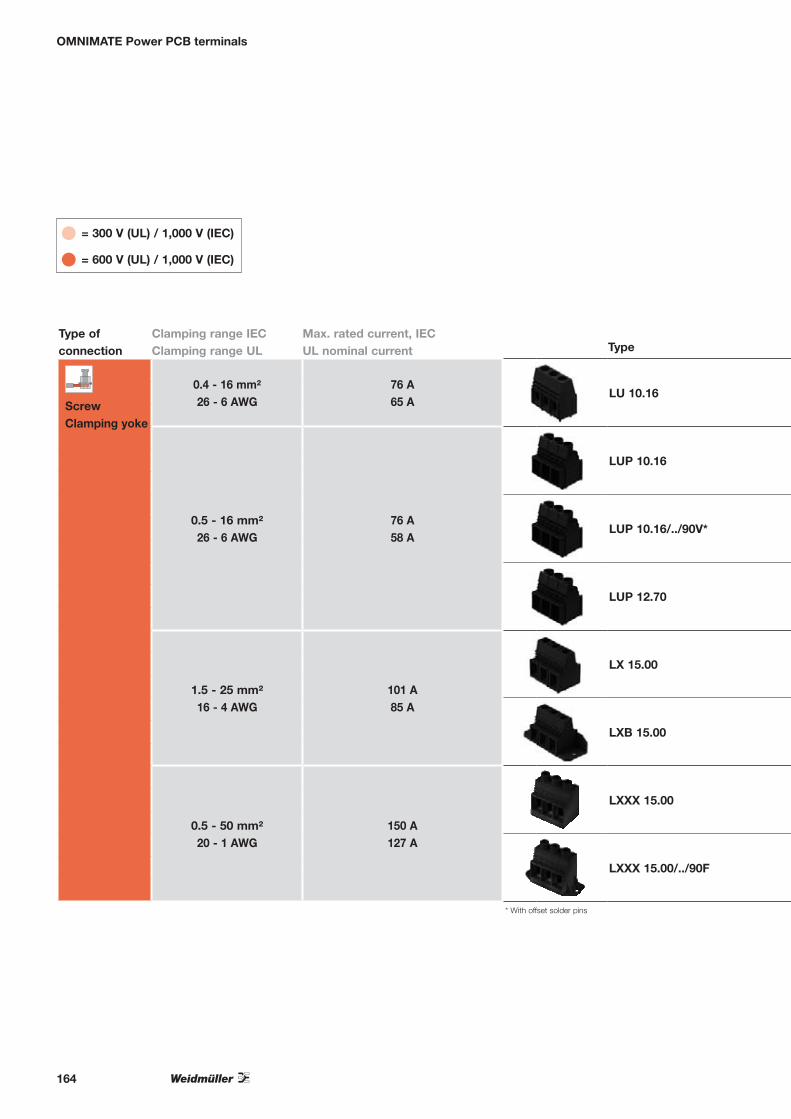
OMNIMATE Power PCB terminals
Pitch, in mm10.16 12.70 15.00
Max. rated voltage, IEC
1,000 V
UL nominal voltage 300 V 600 V
Type of connection
Clamping range IECClamping range UL
Max. rated current, IECUL nominal current Type Page
Screw Clamping yoke
0.4 - 16 mm²26 - 6 AWG
76 A65 A LU 10.16 166
0.5 - 16 mm²26 - 6 AWG
76 A58 A
LUP 10.16 167
LUP 10.16/../90V* 168
LUP 12.70 169
1.5 - 25 mm²16 - 4 AWG
101 A85 A
LX 15.00 170
LXB 15.00 171
0.5 - 50 mm²20 - 1 AWG
150 A127 A
LXXX 15.00 172
LXXX 15.00/../90F 172
= 300 V (UL) / 1,000 V (IEC)
= 600 V (UL) / 1,000 V (IEC)
* With offset solder pins
164

Pitch, in mm10.16 12.70 15.00
Max. rated voltage, IEC
1,000 V
UL nominal voltage 300 V 600 V
Type of connection
Clamping range IECClamping range UL
Max. rated current, IECUL nominal current Type Page
Screw Clamping yoke
0.4 - 16 mm²26 - 6 AWG
76 A65 A LU 10.16 166
0.5 - 16 mm²26 - 6 AWG
76 A58 A
LUP 10.16 167
LUP 10.16/../90V* 168
LUP 12.70 169
1.5 - 25 mm²16 - 4 AWG
101 A85 A
LX 15.00 170
LXB 15.00 171
0.5 - 50 mm²20 - 1 AWG
150 A127 A
LXXX 15.00 172
LXXX 15.00/../90F 172
OMNIMATE Power PCB terminals
165

OMNIMATE Power PCB terminals
LU 10.16/../90
High-power PCB Terminal with clamping yoke screw connection, in 10.16 mm pitch for wire cross-sections up to 16 mm² (AWG 6).• Increased derating reserves because WEMID
insulating material is used.• Wire outlet direction: 90° version.• 2- and 3-pole block construction can be
aligned together for higher pole counts.
Technical dataIn compliance with IEC 60664-1 Clamping range, max. mm²Solid core H05(07) V-U mm²Stranded H07 V-RFlexible H05(07) V-K mm²Flexible with ferrule mm²Ferrule with plastic collar mm²Stripping length mmScrewdriver blade According to normTightening torque range NmRated current, max. AAt ambient temperatureFor conductor cross-section mm²Overvoltage categoryPollution severityRated voltage VRated impulse voltage kVUL / CUL (Use Group)Rated voltage VRated current AAWG conductorCSA (Use Group)Rated voltage VRated current AAWG conductorGeneral dataType of insulation materialFlammability class UL 94Contact base materialMaterial of contact surfacePin dimensions = dSolder eyelet Ø = D mmSolder eyelet Ø tolerance
0.14...160.5...166...16
0.5...162.5...102.5...10
121.0 x 5.5DIN 52641.2...1.5
In compliance with IEC 60664-1 / IEC 61984
mm
AWG
AWG
mm
mm
76 7620°C 40°C
16III III II3 2 2
690 690 1,0006 6 4B C D
300 150 30065 65 10
26-6B C D
300 150 30065 65 10
22-6
Wemid (PA)V-0
E-Cutinned
1.2 x 1.21.6
+ 0,1
Product data
IEC: 1,000 V / 76 A / 0.5 - 16 mm² UL: 300 V / 65 A / AWG 26 - 6
For additional articles and information, refer to
catalog.weidmueller.com
AccessoriesScrewdriver
SD 1,0x5,5x150
SDI 1,0x5,5x125
Order No.9008350000
9008410000
Note:• Additional colours on request• Rated current related to rated cross-section and min. No.
of poles.• Wire end ferrule without plastic collar to DIN 46228/1• Wire end ferrule with plastic collar to DIN 46228/4• P on drg. = pitch• Rated data refer only to the component itself. Clearance and
creepage distances to other components are to be designed in accordance with the relevant application standards.
LU 10.16/../90
Dimensioned drawing
L1+P
L1
P
0,60.024"
18,30.720"
28
,51
.12
2"
6 ,50.255"
10
,16
0.4
00
"
1 ,6+0,10.063"
Ordering dataSolder pin length 4.5 mm
Colour black
Pitch 10.16 mmPol. L1 (inch) Qty. Order No.2 10.16 0.400 20 19341400003 20.32 0.800 20 19214500004 30.48 1.200 20 12262200005 40.64 1.600 20 12262300006 50.80 2.000 20 12262400007 60.96 2.400 20 12262500008 71.12 2.800 20 12262600009 81.28 3.200 20 122627000010 91.44 3.600 20 1226280000
Representative derating curve
166

OMNIMATE Power PCB terminals
LUP 10.16/../90
High-power PCB Terminal with clamping yoke screw connection, in 10.16 mm pitch for wire cross-sections up to 16 mm² (AWG 6).• Increased derating reserves because WEMID
insulating material is used.• Wire outlet direction: 90°• With integrated test point for the PS 2.0 test
plug.
Technical dataIn compliance with IEC 60664-1 Clamping range, max. mm²Solid core H05(07) V-U mm²Stranded H07 V-RFlexible H05(07) V-K mm²Flexible with ferrule mm²Ferrule with plastic collar mm²Stripping length mmScrewdriver blade According to normTightening torque range NmRated current, max. AAt ambient temperatureFor conductor cross-section mm²Overvoltage categoryPollution severityRated voltage VRated impulse voltage kVUL / CUL (Use Group)Rated voltage VRated current AAWG conductorCSA (Use Group)Rated voltage VRated current AAWG conductorGeneral dataType of insulation materialFlammability class UL 94Contact base materialMaterial of contact surfacePin dimensions = dSolder eyelet Ø = D mmSolder eyelet Ø tolerance
0.13...160.5...166...16
0.5...162.5...102.5...10
121.0 x 5.5DIN 52641.2...1.5
In compliance with IEC 60664-1 / IEC 61984
mm
AWG
AWG
mm
mm
76 7220°C 40°C
16III III II3 2 2
800 1,000 1,0008 8 6B C D
300 300 30058 58 10
26-6B C D
300 300 30058 58 10
22-6
Wemid (PA)V-0
E-Cutinned
1.2 x 1.21.6
+ 0,1
Product data
IEC: 1,000 V / 76 A / 0.5 - 16 mm² UL: 300 V / 58 A / AWG 26 - 6
For additional articles and information, refer to
catalog.weidmueller.com
AccessoriesScrewdriver
SD 1,0x5,5x150
SDI 1,0x5,5x125
Crosshead screwdriver
SDIK PZ2
SDK PZ2
Test plug
PS 2.0 MC
Order No.9008350000
9008410000
9008890000
9008540000
0310000000
Note:• Additional colours on request• Rated current related to rated cross-section and min. No.
of poles.• Wire end ferrule without plastic collar to DIN 46228/1• Wire end ferrule with plastic collar to DIN 46228/4• P on drg. = pitch• Rated data refer only to the component itself. Clearance and
creepage distances to other components are to be designed in accordance with the relevant application standards.
LUP 10.16/../90
with test point
Dimensioned drawing
L1
P
L1+P 0,80.031"
25,10.987"
31
,5
1.2
40
"
11 ,10.439"
10
,16
0.4
00
"
1 ,6+0,10.063"
Ordering dataSolder pin length 3.2 mm
Colour black
Pitch 10.16 mmPol. L1 (inch) Qty. Order No.2 10.12 0.400 20 12262900003 20.24 0.800 20 12263000004 30.48 1.200 20 12263100005 40.64 1.600 20 12263200006 50.80 2.000 20 12263300007 60.96 2.400 20 12263400008 71.12 2.800 20 12263500009 81.28 3.200 20 1226360000
Representative derating curve
167

OMNIMATE Power PCB terminals
LUP 10.16/../90V
High-power PCB Terminal with clamping yoke screw connection, in 10.16 mm pitch for wire cross-sections up to 16 mm² (AWG 6).• UL 600 V approval.• Increased derating reserves because WEMID
insulating material is used.• Wire outlet direction: 90°.• With integrated test point for PS 2.0 test plug.
Technical dataIn compliance with IEC 60664-1 Clamping range, max. mm²Solid core H05(07) V-U mm²Stranded H07 V-RFlexible H05(07) V-K mm²Flexible with ferrule mm²Ferrule with plastic collar mm²Stripping length mmScrewdriver blade According to normTightening torque range NmRated current, max. AAt ambient temperatureFor conductor cross-section mm²Overvoltage categoryPollution severityRated voltage VRated impulse voltage kVUL / CUL (Use Group)Rated voltage VRated current AAWG conductorCSA (Use Group)Rated voltage VRated current AAWG conductorGeneral dataType of insulation materialFlammability class UL 94Contact base materialMaterial of contact surfacePin dimensions = dSolder eyelet Ø = D mmSolder eyelet Ø tolerance
0.13...160.5...166...16
0.5...162.5...102.5...10
121.0 x 5.5DIN 52641.2...1.5
In compliance with IEC 60664-1 / IEC 61984
mm
AWG
AWG
mm
mm
76 7220°C 40°C
16III III II3 2 2
800 1,000 1,0008 8 6B C D
600 600 60051 51 5
22-6B C D
600 600 60051 51 5
22-6
Wemid (PA)V-0
E-Cutinned
1.2 x 1.21.6
+ 0,1
Product data
IEC: 1,000 V / 76 A / 0.5 - 16 mm² UL: 600 V / 51 A / AWG 22 - 6
For additional articles and information, refer to
catalog.weidmueller.com
AccessoriesScrewdriver
SD 1,0x5,5x150
SDI 1,0x5,5x125
Crosshead screwdriver
SDIK PZ2
SDK PZ2
Test plug
PS 2.0 MC
Order No.9008350000
9008410000
9008890000
9008540000
0310000000
Note:• Additional colours on request• Rated current related to rated cross-section and min. No.
of poles.• Wire end ferrule without plastic collar to DIN 46228/1• Wire end ferrule with plastic collar to DIN 46228/4• P on drg. = pitch• Rated data refer only to the component itself. Clearance and
creepage distances to other components are to be designed in accordance with the relevant application standards.
LUP 10.16/../90V
Dimensioned drawing
L1 + P
L1
P
0,80.031"
25,10.987"
11,10.439"
Ø 1,6 + 0,10.063"
31,5
1.24
0"
10,1
60.
400"
Ordering dataSolder pin length 3.2 mm
Colour black
Pitch 10.16 mmPol. L1 (inch) Qty. Order No.2 10.16 0.400 20 11929800003 20.32 0.800 20 11929900004 30.48 1.200 20 11930000005 40.64 1.600 20 11930100006 50.80 2.000 20 11930200007 60.96 2.400 20 11930300008 71.12 2.800 20 11930400009 81.28 3.200 20 1193050000
Representative derating curve
with test point
168
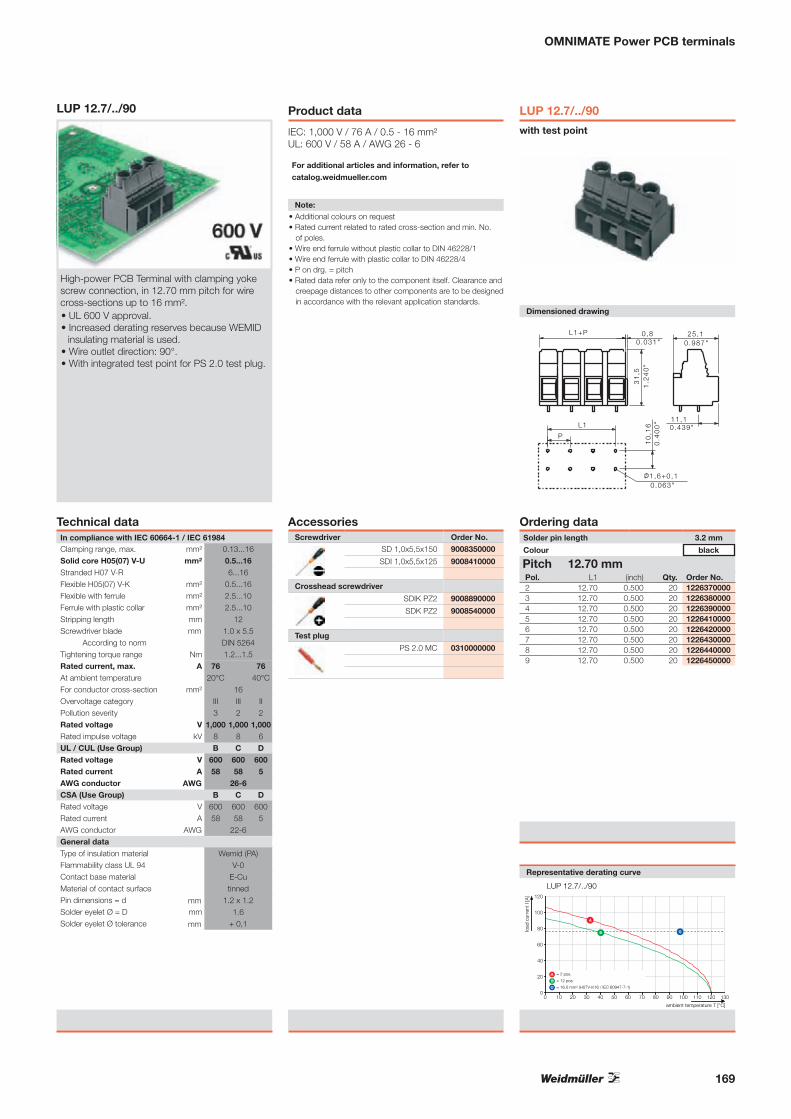
OMNIMATE Power PCB terminals
LUP 12.7/../90
High-power PCB Terminal with clamping yoke screw connection, in 12.70 mm pitch for wire cross-sections up to 16 mm².• UL 600 V approval.• Increased derating reserves because WEMID
insulating material is used.• Wire outlet direction: 90°.• With integrated test point for PS 2.0 test plug.
Technical dataIn compliance with IEC 60664-1 Clamping range, max. mm²Solid core H05(07) V-U mm²Stranded H07 V-RFlexible H05(07) V-K mm²Flexible with ferrule mm²Ferrule with plastic collar mm²Stripping length mmScrewdriver blade According to normTightening torque range NmRated current, max. AAt ambient temperatureFor conductor cross-section mm²Overvoltage categoryPollution severityRated voltage VRated impulse voltage kVUL / CUL (Use Group)Rated voltage VRated current AAWG conductorCSA (Use Group)Rated voltage VRated current AAWG conductorGeneral dataType of insulation materialFlammability class UL 94Contact base materialMaterial of contact surfacePin dimensions = dSolder eyelet Ø = D mmSolder eyelet Ø tolerance
0.13...160.5...166...16
0.5...162.5...102.5...10
121.0 x 5.5DIN 52641.2...1.5
In compliance with IEC 60664-1 / IEC 61984
mm
AWG
AWG
mm
mm
76 7620°C 40°C
16III III II3 2 2
1,000 1,000 1,0008 8 6B C D
600 600 60058 58 5
26-6B C D
600 600 60058 58 5
22-6
Wemid (PA)V-0
E-Cutinned
1.2 x 1.21.6
+ 0,1
Product data
IEC: 1,000 V / 76 A / 0.5 - 16 mm² UL: 600 V / 58 A / AWG 26 - 6
For additional articles and information, refer to
catalog.weidmueller.com
AccessoriesScrewdriver
SD 1,0x5,5x150
SDI 1,0x5,5x125
Crosshead screwdriver
SDIK PZ2
SDK PZ2
Test plug
PS 2.0 MC
Order No.9008350000
9008410000
9008890000
9008540000
0310000000
Note:• Additional colours on request• Rated current related to rated cross-section and min. No.
of poles.• Wire end ferrule without plastic collar to DIN 46228/1• Wire end ferrule with plastic collar to DIN 46228/4• P on drg. = pitch• Rated data refer only to the component itself. Clearance and
creepage distances to other components are to be designed in accordance with the relevant application standards.
LUP 12.7/../90
with test point
Dimensioned drawing
0,8L1+P0.031"
31
,51
.24
0"
25 ,10.987"
11,10.439"
10
,16
0.4
00
"
1 ,6+0,10.063"
L1
P
Ordering dataSolder pin length 3.2 mm
Colour black
Pitch 12.70 mmPol. L1 (inch) Qty. Order No.2 12.70 0.500 20 12263700003 12.70 0.500 20 12263800004 12.70 0.500 20 12263900005 12.70 0.500 20 12264100006 12.70 0.500 20 12264200007 12.70 0.500 20 12264300008 12.70 0.500 20 12264400009 12.70 0.500 20 1226450000
Representative derating curve
169

OMNIMATE Power PCB terminals
LX 15.00/../90
High-power PCB Terminal with clamping yoke screw connection, in 15.00 mm pitch for wire cross-sections up to 25 mm² (AWG 4).• UL 600 V approval.• Increased derating reserves because WEMID
insulating material is used.• Wire outlet direction: 90°.• With integrated test point for PS 2.0 test plug.• Versions up to 8 poles have block
construction.• Available with and without mounting flange.
Technical dataIn compliance with IEC 60664-1 Clamping range, max. mm²Solid core H05(07) V-U mm²Stranded H07 V-RFlexible H05(07) V-K mm²Flexible with ferrule mm²Ferrule with plastic collar mm²Stripping length mmScrewdriver blade According to normTightening torque range NmRated current, max. AAt ambient temperatureFor conductor cross-section mm²Overvoltage categoryPollution severityRated voltage VRated impulse voltage kVUL / CUL (Use Group)Rated voltage VRated current AAWG conductorCSA (Use Group)Rated voltage VRated current AAWG conductorGeneral dataType of insulation materialFlammability class UL 94Contact base materialMaterial of contact surfacePin dimensions = dSolder eyelet Ø = D mmSolder eyelet Ø tolerance
1.31...251.5...166...25
1.5...251.5...161.5...16
161.0 x 5.5DIN 5264
2.4...4
In compliance with IEC 60664-1 / IEC 61984
mm
AWG
AWG
mm
mm
101 10120°C 40°C
25III III II3 2 2
1,000 1,000 1,0008 8 6B C D
600 600 60085 85 5
16-4B C D
600 600 60085 85 5
16-4
Wemid (PA)V-0
E-Cutinned
1.2 x 1.21.6
+ 0,1
Product data
IEC: 1,000 V / 101 A / 1.5 - 25 mm² UL: 600 V / 85 A / AWG 16 - 4
For additional articles and information, refer to
catalog.weidmueller.com
AccessoriesScrewdriver
SD 1,2x6,5x150
SDI 1,2x6,5x150
Crosshead screwdriver
SDIK PZ2
SDK PZ2
Test plug
PS 2.0 MC
Order No.9009010000
9008420000
9008890000
9008540000
0310000000
Note:• Additional colours on request• Rated current related to rated cross-section and min. No.
of poles.• Wire end ferrule without plastic collar to DIN 46228/1• Wire end ferrule with plastic collar to DIN 46228/4• P on drg. = pitch• Rated data refer only to the component itself. Clearance and
creepage distances to other components are to be designed in accordance with the relevant application standards.
LX 15.00/../90
with test point
Dimensioned drawing
L1
P
L1 + 13 29 ,11 .144"L1 + 0 .512"
13 ,50 .531"
3 ,80 .15"
Ø 1 ,6 + 0 ,10 .063"
37
1.4
57
"1
2,5
0.4
92
"
Ordering dataSolder pin length 4.5 mm
Colour black
Pitch 15.00 mmPol. L1 (inch) Qty. Order No.1 0.00 0.000 20 12264600002 15.00 0.591 20 12264700003 30.00 1.181 20 11747200004 45.00 1.772 20 12264800005 60.00 2.362 20 12264900006 75.00 2.953 20 12265000007 90.00 3.543 20 12265100008 105.00 4.134 10 1921480000
Representative derating curve
170
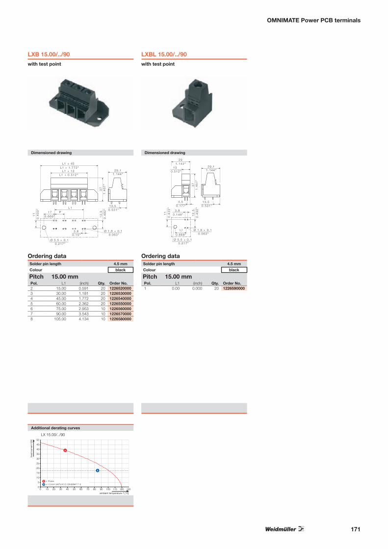
OMNIMATE Power PCB terminals
LXB 15.00/../90
with test point
Dimensioned drawing
L1P
L1 + 45
29 ,11 .144"
L1 + 1 .772"L1 + 13
L1 + 0 .512"
13 ,50 .531"
170 .669"
3 ,80 .15"
Ø 1 ,6 + 0 ,10 .063"
Ø 5 ,5 + 0 ,10 .217"
37
1.4
57
"1
2,5
0.4
92
"
11
0.4
33
"
Ordering dataSolder pin length 4.5 mm
Colour black
Pitch 15.00 mmPol. L1 (inch) Qty. Order No.2 15.00 0.591 20 12265200003 30.00 1.181 20 12265300004 45.00 1.772 20 12265400005 60.00 2.362 20 12265500006 75.00 2.953 10 12265600007 90.00 3.543 10 12265700008 105.00 4.134 10 1226580000
Additional derating curves
LXBL 15.00/../90
with test point
Dimensioned drawing
29
29 ,11 .144"
1 .142"13
0 .512"
13 ,50 .531"
170 .669"
3 ,80 .149"
4 ,50 .177"
Ø 1 ,6 + 0 ,10 .063"
Ø 5 ,5 + 0 ,10 .217"
37
1.4
57
"1
2,5
0.4
92
"
11
0.4
33
"
Ordering dataSolder pin length 4.5 mm
Colour black
Pitch 15.00 mmPol. L1 (inch) Qty. Order No.1 0.00 0.000 20 1226590000
171

OMNIMATE Power PCB terminals
LXXX 15.00/../90
High-power PCB Terminal with clamping yoke screw connection, in 15.00 mm pitch for wire cross-sections up to 50 mm² (AWG 1).• UL 600 V approval for unlimited international
usage in devices.• Increased derating reserves because WEMID
insulating material is used.• Wire outlet direction of 90°.• With integrated test point for PS 2.0 test plug.• Versions up to 8 poles have block
construction.• Available with and without mounting flange.
Technical dataIn compliance with IEC 60664-1 Clamping range, max. mm²Solid core H05(07) V-U mm²Stranded H07 V-RFlexible H05(07) V-K mm²Flexible with ferrule mm²Ferrule with plastic collar mm²Stripping length mmScrewdriver blade According to normTightening torque range NmRated current, max. AAt ambient temperatureFor conductor cross-section mm²Overvoltage categoryPollution severityRated voltage VRated impulse voltage kVUL / CUL (Use Group)Rated voltage VRated current AAWG conductorCSA (Use Group)Rated voltage VRated current AAWG conductorGeneral dataType of insulation materialFlammability class UL 94Contact base materialMaterial of contact surfacePin dimensions = dSolder eyelet Ø = D mmSolder eyelet Ø tolerance
0.5...500.5...166...50
0.5...350.5...350.5...35
181.2 x 6.5DIN 5264
2.5...4
In compliance with IEC 60664-1 / IEC 61984
mm
AWG
AWG
mm
mm
150 15020°C 40°C
35III III II3 2 2
1,000 1,000 1,0008 8 8B C D
600 600 600127 127 5
20-1B C D
600 600 600127 127 5
20-1
Wemid (PA)V-0
Copper alloytinned
1.2 x 1.21.6
+ 0,1
Product data
IEC: 1,000 V / 150 A / 0.5 - 50 mm² UL: 600 V / 127 A / AWG 20 - 1
For additional articles and information, refer to
catalog.weidmueller.com
AccessoriesScrewdriver
SD 1,2x6,5x150
SDI 1,2x6,5x150
Crosshead screwdriver
SDIK PZ2
SDK PZ2
Test plug
PS 2.0 MC
Order No.9009010000
9008420000
9008890000
9008540000
0310000000
Note:• Additional colours on request• Rated current related to rated cross-section and min. No.
of poles.• Wire end ferrule without plastic collar to DIN 46228/1• Wire end ferrule with plastic collar to DIN 46228/4• P on drg. = pitch• Rated data refer only to the component itself. Clearance and
creepage distances to other components are to be designed in accordance with the relevant application standards.
• IP 20 from 16 mm² to 50 mm²
LXXX 15.00/../90
with test point
Dimensioned drawing
L1 + 16L1 + 0.63"
Ø 1,6 + 0,10.063"
L1
P
311.22"
15,40.606"
12,5
0.49
2"
3,80.15"
51,5
2.02
8"
Ordering dataSolder pin length 4.5 mm
Colour black
Pitch 15.00 mmPol. L1 (inch) Qty. Order No.1 0.00 0.000 20 10471200002 15.00 0.591 20 10471300003 30.00 1.181 10 10471400004 45.00 1.772 10 1047150000
Representative derating curve
172

OMNIMATE Power PCB terminals
LXXX 15.00/../90F
with test point
Dimensioned drawing
L1 + 45L1 + 1.772"
Ø 1,6 + 0,10.063"
L1P
311.22"
15,40.606"
12,5
0.49
2"
3,80.15"
51,5
2.02
8"
Ø 5,5 + 0,10.217"
L1 + 16L1 + 0.63"
170.669"
110.
433"
Ordering dataSolder pin length 4.5 mm
Colour black
Pitch 15.00 mmPol. L1 (inch) Qty. Order No.1 0.00 0.000 20 10472800002 15.00 0.591 20 10472900003 30.00 1.181 10 10473000004 45.00 1.772 10 1047310000
Additional derating curves
LXXX 15.00/../90FL
with test point
Dimensioned drawing
L1 + 30,5L1 + 1.201"
Ø 1,6 + 0,10.063"
L1P
311.22"
15,40.606"
12,5
0.49
2"
3,80.15"
51,5
2.02
8"
Ø 5,5 + 0,10.217"
L1 + 16L1 + 0.63"
170.669"
110.
433"
Ordering dataSolder pin length 4.5 mm
Colour black
Pitch 15.00 mmPol. L1 (inch) Qty. Order No.1 0.00 0.000 20 10474400002 15.00 0.591 20 10474500003 30.00 1.181 10 10474600004 45.00 1.772 10 1047470000
LXXX 15.00/../90FR
with test point
Dimensioned drawing
L1 + 30,5L1 + 1.201"
Ø 1,6 + 0,10.063"
L1P
311.22"
15,40.606"
12,5
0.49
2" 3,80.15"
51,5
2.02
8"
Ø 5,5 + 0,10.217"
L1 + 16L1 + 0.63"
170.669"
110.
433"
Ordering dataSolder pin length 4.5 mm
Colour black
Pitch 15.00 mmPol. L1 (inch) Qty. Order No.1 0.00 0.000 20 10476000002 15.00 0.591 20 10476100003 30.00 1.181 10 10476200004 45.00 1.772 10 1047630000
173
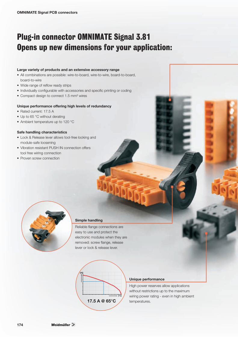
OMNIMATE Signal PCB connectors
Plug-in connector OMNIMATE Signal 3.81Opens up new dimensions for your application:
Large variety of products and an extensive accessory range• All combinations are possible: wire-to-board, wire-to-wire, board-to-board,
board-to-wire • Wide range of reflow ready strips • Individually configurable with accessories and specific printing or coding• Compact design to connect 1.5 mm² wires
Unique performance offering high levels of redundancy• Rated current: 17.5 A • Up to 65 °C without derating• Ambient temperature up to 120 °C
Safe handling characteristics • Lock & Release lever allows tool-free locking and
module-safe loosening• Vibration resistant PUSH IN connection offers
tool free wiring connection • Proven screw connection
Reliable flange connections are easy to use and protect the electronic modules when they are removed: screw flange, release lever or lock & release lever.
Simple handling
High power reserves allow applications without restrictions up to the maximum wiring power rating - even in high ambient temperatures.
Unique performance
[A]
[°C]
17.5 A @ 65°C
174

OMNIMATE Signal PCB connectors
PUSH IN spring connection technology: direct connection without tools – simply plug in the prepared conductors – finished! Intuitive operation using large release buttons.
Maintenance-free, secure, vibration-proof
ä
Minimum stack height, maximum clamping force and PUSH IN: the SCDN 3.81 simply handles two 7.9 mm flat BCF 3.81 with 1.5 mm² wire end ferrules.
Less space required
ä
For further information, please ask for our catalogue:
OMNIMATE – Device connectivityOrder number: 1271680000
OMNIMATE – Geräteanschlusstechnik für LED-BeleuchtungssteuerungenAnschlusslösungen passgenau integrieren
175

OMNIMATE Signal PCB connectors
Male header Male header Male plug
Levels 1 2 1Orientation 90° 180° 135° 270° 90° 180° 90° 90° 180° 180°
Solder connection
Solder connection Screw
Type SC SC SC SC SCD SCD SCDN SCDV SCDV SCZ
Flange options G/F G/F G/F G/F G/F G/F G/F G/F G/F G/F/FI/LR
Reflow solder connection Reflow solder connection
Type SC-SMT SC-SMT SC-SMT SC-SMT SCD-THR SCD-THR SCDN-THR SCDV-THR SCDV-THR
Flange options G/LF G/LF G/LF G/F G/F G/F G/F G/F G/F
Fem
ale
plu
g
Screw
BCZ 180° (G)/F/LR
BCZ 90° (G)/F
BCZ 270° (G)/F
PUSH IN
BCF 180° (G)/F/LR
So
cket
blo
cks
Solder connection
BCLSMT
90° (G)/F/LFI
BCLSMT
180° (G)/LFI
= Wire to board
= Board to board
= Wire to wire
= Board to wire
Female plug and header: (G)* = Closed (without flange) F = Flange with screw LFI = Inverted solder flange with nut LR = Lock & Release lever
* not included in the article description
Male header and plug: G = Closed (without flange) F = Screw flange with nut LF = Solder flange with nut LR = Lock & Release lever FI = Inverted flange with screw
Orientation
180º
270º
135º
90º
270º
90º
180º
225º
176

OMNIMATE Signal PCB connectors
Male header Male header Male plug
Levels 1 2 1Orientation 90° 180° 135° 270° 90° 180° 90° 90° 180° 180°
Solder connection
Solder connection Screw
Type SC SC SC SC SCD SCD SCDN SCDV SCDV SCZ
Flange options G/F G/F G/F G/F G/F G/F G/F G/F G/F G/F/FI/LR
Reflow solder connection Reflow solder connection
Type SC-SMT SC-SMT SC-SMT SC-SMT SCD-THR SCD-THR SCDN-THR SCDV-THR SCDV-THR
Flange options G/LF G/LF G/LF G/F G/F G/F G/F G/F G/F
Fem
ale
plu
g
Screw
BCZ 180° (G)/F/LR
BCZ 90° (G)/F
BCZ 270° (G)/F
PUSH IN
BCF 180° (G)/F/LR
So
cket
blo
cks
Solder connection
BCLSMT
90° (G)/F/LFI
BCLSMT
180° (G)/LFI
Complete system for all possible combinations and a comprehensive range of accessories
Wire to wire
Wire to board
Board to board
Board to wire
177

Industrial Ethernet
Industrial Ethernet for photovoltaic systems
Active and passive components for efficient networking in your photovoltaic systems
The aim of using components from the Industrial Ethernet branch, is that all devices within a system network together using just one bus technology for the whole system. Thereby process data and diagnostic functions can be exchanged independently of the device between the network participants, and also centrally monitored and controlled. Weidmüller offers for the networking of PV systems a comprehensive line of active and passive networking components.
This consists of the following individual components:
• Unmanaged and managed switches• Media converters • Power-over-Ethernet Switches• Industrial wireless components• Serial/Ethernet converters• Plug-in connectors for copper and fibre optic transmission
Serial/Ethernet converters allow access to components with serial interfaces over the Ethernet network, like controllers, measuring devices or inverters for example.
Investment protection
Media converters for conversion between copper and glass fibre media as well as for bridging larger distances for applications over a wide area.
Media flexibility
178

Industrial Ethernet
Thanks to Plug & Play unmanaged switches, connecting controllers or power meters into Ethernet networks is possible without any configuration effort.
Simple and quick component integration
The integrated ring-redundancy mechanism of the managed switches with a recovery time of ≤ 20 ms, avoids network failures in the PV system.
High system availabilityRecovery Time
< 20 ms
Compact RJ45 plugs for high data transmission rates for use in IP 67 outdoor applications.
Compact and reliable
RJ45 Push Pull plug for tool-less on-site assembly with an easy handling locking mechanism.
Simple handling
For further information, please ask for our catalogue:
Industrial EthernetOrder number: 1274570000
9
Ind
ust
rial
Eth
ern
etK
atal
og
201
1/20
12
Industrial EthernetKatalog
2011 |2012
9KA
TA
LOG
Bestellnummer:1274560000/06/2011/SMMD
www.weidmueller.com
ÄgyptenArgentinienAserbaidschanAustralienBahrainBelgienBosnien undHerzegowinaBrasilienBulgarienChileChinaCosta RicaDänemarkDeutschlandEcuadorEstlandFinnlandFrankreichGriechenlandGroßbritannienHongkong IndienIndonesienIranIrlandIslandIsraelItalienJapanJordanien
KanadaKasachstanKatarKolumbienKoreaKroatienKuwaitLettlandLibanonLitauenLuxemburgMalaysiaMaltaMazedonienMexikoMoldauNeuseelandNiederlandeNorwegenOmanÖsterreichPakistanPeruPhilippinenPolenPortugalRumänienRusslandSaudi-ArabienSchwedenSchweiz
SerbienSingapurSlowakeiSlowenienSpanienSüdafrikaTaiwanThailandTschechienTunesienTürkeiUkraineUngarnUruguayUsbekistanVenezuelaVereinigteArabischeEmirateVereinigteStaatenVietnamWeißrussland
Weidmüller ist weltweit führender Anbieter vonLösungen für die elektrische Verbindung, Übertragungund Wandlung von Energie, Signalen und Daten imindustriellen Umfeld.
Das Unternehmen mit Hauptsitz in Detmold entwickelt, produziert und vertreibt weltweit Produkte der elektrischen Verbindungstechnik und der Elektronik.Über ein Netzwerk von Applikationsspezialisten bietetWeidmüller Engineering-Dienstleistungen an undentwickelt anwendungsspezifische Lösungen.
Das gesamte Produkt- und Leistungsspektrum sichertunseren Kunden und Weidmüller in gleicher Weisedauerhaft Wettbewerbs- und Wertvorteile.
179
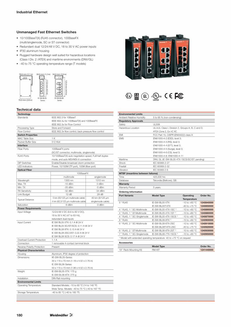
Industrial Ethernet
Unmanaged Fast Ethernet Switches
• 10/100BaseT(X) (RJ45 connector), 100BaseFX (multi/singlemode, SC or ST connector)
• Redundant dual 12/24/48 V DC, 18 to 30 V AC power inputs• IP30 aluminum housing• Rugged hardware design well suited for hazardous locations
(Class I Div. 2 /ATEX) and maritime environments (DNV/GL)• -40 to 75 °C operating temperature range (T models)
Technical dataTechnologyStandards IEEE 802.3 for 10BaseT
IEEE 802.3u for 100BaseT(X) and 100BaseFX
IEEE 802.3x for Flow Control
Processing Type Store and Forward
Flow Control IEEE 802.3x flow control, back pressure flow control
Switch Properties
MAC Table Size 1 K
Packet Buffer Size 512 Kbit
Interface
Fiber Ports 100BaseFX ports
(SC/ST connector, multimode, singlemode)
RJ45 Ports 10/100BaseT(X) auto negotiation speed, Full/Half duplex
mode, and auto MDI/MDI-X connection
DIP Switches Enable/Disable broadcast storm protection
LED Indicators Power, 10/100M (TP port), 100M (fiber port)
Optical Fiber
100BaseFX
multimode singlemode
Wavelength 1300 nm 1310 nm
Max. TX -10 dBm 0 dBm
Min. TX -20 dBm -5 dBm
RX Sensitivity -32 dBm -34 dBm
Link Budget 12 dB 29 dB
Typical Distance5 km (50/125 μm multimode cable)
4 km (62,5/125 μm multimode cable)
40 km (9/125 μm
singlemode cable)
Saturation -6 dBm -3 dBm
Power Requirements
Input Voltage 12/24/48 V DC (9.6 to 60 V DC),
18 to 30 V AC (47 to 63 Hz),
redundant dual inputs
Input Current IE SW BL05 5TX: 0.1 A @ 24 V
IE SW BL05 SC/ST/SCS: 0.11 A @ 24 V
IE SW BL08 8TX: 0.13 A @ 24 V
IE SW BL08 2SC/2ST: 0.22 A @ 24 V
IE SW BL08 SCS: 0.17 A @ 24 V
Overload Current Protection 1.1 A
Connection 1 removable 4-contact terminal block
Reverse Polarity Protection Present
Physical Characteristics
Housing Aluminum, IP30 degree of protection
Dimensions IIE-SW-BL05-Series:
30 x 115 x 70 mm (1.18 x 4.52 x 2.76 in)
IE-SW-BL08-Series:
50 x 115 x 70 mm (1.96 x 4.52 x 2.76 in)
Weight IE-SW-BL05-5TX: 175 g
IE-SW-BL08-8TX: 275 g
Installation DIN-Rail mounting
Environmental Limits
Operating Temperature Standard Models: -10 to 60 °C (14 to 140 °F)
Wide Temp. Models: -40 to 75 °C (-40 to 167 °F)
Storage Temperature -40 to 85 °C (-40 to 185 °F)
Environmental LimitsAmbient Relative Humidity 5 to 95 % (non-condensing)
Regulatory Approvals
Safety UL508
Hazardous Location UL/cUL Class I, Division 2, Groups A, B, C and D;
ATEX Zone 2, Ex nC IIC
EMI FCC Part 15, CISPR (EN55022) class A
EMS EN61000-4-2 (ESD), level 3;
EN61000-4-3 (RS), level 3;
EN61000-4-4 (EFT), level 3;
EN61000-4-5 (Surge), level 3;
EN61000-4-6 (CS), level 3;
EN61000-4-8; EN61000-4-11
Maritime DNV, GL (IE-SW-BL05-4TX-1SCS/SC/ST: pending)
Shock IEC 60068-2-27
Freefall IEC 60068-2-32
Vibration IEC 60068-2-6
MTBF (meantime between failures)
Time 425,000 hrs
Database Telcordia (Bellcore), GB
Warranty
Warranty Period 5 years
T ; u \ %
30.0 mm (1.2 in)
115.0 mm
(4.5 in)
50.0 mm (2.0 in)78.8 mm (3.1 in)
70.0 mm (2.8 in)IE-SW-BL05-
SeriesIE-SW-BL08-
Series
125.0 mm
(4.9 in)
Ordering Information
Port Variants Model Type Operating
Temperature
Order No.
5 * RJ45 IE-SW-BL05-5TX -10 to +60 °C 1240840000IE-SW-BL05T-5TX -40 to +75 °C 1240850000
4 * RJ45, 1 * SC-Multimode IE-SW-BL05-4TX-1SC 1) -10 to +60 °C 1240890000
4 * RJ45, 1 * ST-Multimode IE-SW-BL05-4TX-1ST 1) -10 to +60 °C 1240880000
4 * RJ45, 1 * SC-Singlemode IE-SW-BL05-4TX-1SCS 1) -10 to +60 °C 1240870000
8 * RJ45 IE-SW-BL08-8TX 1) -10 to +60 °C 1240900000
6 * RJ45, 2 * SC-Multimode IE-SW-BL08-6TX-2SC -10 to +60 °C 1240910000IE-SW-BL08T-6TX-2SC -40 to +75 °C 1240920000
6 * RJ45, 2 * ST-Multimode IE-SW-BL08-6TX-2ST 1) -10 to +60 °C 1240930000
7 * RJ45, 1 * SC-Singlemode IE-SW-BL08-7TX-1SCS 1) -10 to +60 °C 12409500001) Model with extended operating temperature -40 to +75 °C on request
Accessories
Model Type Order No.
19'' Rack Mounting Kit RM-KIT 1241440000
180

Industrial Ethernet
Unmanaged Fast Ethernet Switches
• Redundant dual 24 V DC power inputs• Relay output warning for power failure and port break alarm• Broadcast storm protection• Transparent transmission of VLAN tagged packets• -40 to 75 °C operating temperature range (T models)
Technical dataTechnologyStandards IEEE 802.3 for 10BaseT
IEEE 802.3u for 100BaseT(X) and 100BaseFX
IEEE 802.3x for Flow Control
Processing Type Store and Forward
Flow Control IEEE 802.3x flow control, back pressure flow
control
Switch Properties
MAC Table Size 1 K (IE-SW-VL09...Series), 4 K (IE-SW-VL16...Series)
Packet Buffer Size 512 Kbit (IE-SW-VL09...Series),
1.5 Mbit (IE-SW-VL16...Series)
Interface
Fiber Ports 100BaseFX ports (SC/ST connector)
RJ45 Ports 10/100BaseT(X) auto negotiation speed,
Full/Half duplex mode, and auto MDI/MDI-X
connection
DIP Switches Port break alarm mask
LED Indicators PWR1, PWR2, FAULT, 10/100M (TP port),
100M (fiber port)
Alarm Contact 1 relay output with current carrying capacity
of 1 A @ 24 V DC
Optical Fiber
100BaseFX
multimode
Wavelength 1300 nm
Max. TX -10 dBm
Min. TX -20 dBm
RX Sensitivity -32 dBm
Link Budget 12 dB
Typical Distance5 km (50/125 μm multimode cable)
4 km (62,5/125 μm multimode cable)
Saturation -6 dBm
Power Requirements
Input Voltage IE-SW-VL09...16-Ports: 24 V DC
(12 to 45 V DC), redundant dual inputs
Input Current IE-SW-VL09T-6TX-3SC: 0.31 A @ 24 V
IE-SW-VL16-16TX: 0.27 A @ 24 V
IE-SW-VL16 SC/ST: 0.44 A @ 24 V
Power Requirements
Overload Current Protection IE-SW-VL09/16...Series: 1.6 A
Connection 1 removable 6-pin terminal blocks
Reverse Polarity Protection Present
Physical Characteristics
Housing Metal, IP30 degree of protection
Dimensions
IE-SW-VL09...Series:
53.6 x 135 x 105 mm
(2.11 x 5.31 x 4.13 in)
IE-SW-VL16...Series:
80.5 x 135 x 105 mm
(3.16 x 5.31 x 4.13 in)
Weight IE-SW-VL09: 630 g
IE-SW-VL16: 1140g
Physical CharacteristicsInstallation DIN-Rail mounting
Environmental Limits
Operating Temperature Standard Models: 0 to 60 °C (32 to 140 °F)
Wide Temp. Models: -40 to 75 °C
(-40 to 167 °F)
Storage Temperature -40 to 85 °C (-40 to 185 °F)
Ambient Relative Humidity 5 to 95 % (non-condensing)
Regulatory Approvals
Safety IE-SW-VL09...Series: UL508, UL60950-1,
CSA C22.2 No. 60950-1, EN60950-1
IE-SW-VL16...Series: UL508, UL60950-1,
EN60950-1
Hazardous Location UL/cUL Class I, Division 2, Groups A, B, C
and D; ATEX Zone 2, Ex nC IIC
EMI FCC Part 15, CISPR (EN55022) class A
EMS EN61000-4-2 (ESD), level 3;
EN61000-4-3 (RS), level 3;
EN61000-4-4 (EFT), level 3;
EN61000-4-5 (Surge), level 3;
EN61000-4-6 (CS), level 3;
Maritime DNV, GL
Shock IEC 60068-2-27
Freefall IEC 60068-2-32
Vibration IEC 60068-2-6
MTBF (meantime between failures)
Time IE-SW-VL09...Series: 396,000 hrs
IE-SW-VL16...Series: 257,000 hrs
Database MIL-HDBK-217F, GB 25 °C
Warranty
Warranty Period 5 years
T ; u \ %
135.0 mm
(5.3 in)
135.0 mm
(5.3 in)
105.0 mm (4.1 in) 80.5 mm (3.2 in)
IE-SW-VL16-Series
2
4
6
1
3
5
7
100M
10M
8
TX
RX
TX
RX
9
FAULT
PWR2
PWR1
100M 100M
100M
53.6 mm (2.1 in)
IE-SW-VL09-Series
Ordering Information
Port Variants Model Type Operating
Temperature
Order No.
16 * RJ45 IE-SW-VL16-16TX 1) 0 to 60 °C 1241000000
6 * RJ45, 3 * SC-Multimode IE-SW-VL09T-6TX-3SC -40 to +75 °C 1240980000
14 * RJ45, 2 * SC-Multimode IE-SW-VL16-14TX-2SC 1) 0 to 60 °C 1241030000
14 * RJ45, 2 * ST-Multimode IE-SW-VL16-14TX-2ST 1) 0 to 60 °C 12410500001) Model with extended operating temperature -40 to +75 °C on request
Accessories
Model Type Order No.
19'' Rack Mounting Kit RM-KIT 1241440000
181
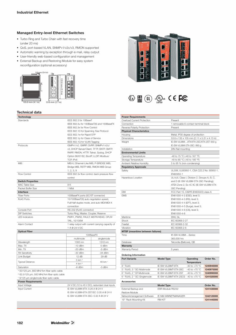
Industrial Ethernet
T ; u \ %
Managed Entry-level Ethernet Switches
• Turbo Ring and Turbo Chain with fast recovery time (under 20 ms)
• QoS, port-based VLAN, SNMPv1/v2c/v3, RMON supported• Automatic warning by exception through e-mail, relay output• User-friendly web-based configuration and management• External Backup and Restoring Module for easy system
reconfiguration (optional accessory)
Technical dataTechnologyStandards IEEE 802.3 for 10BaseT
IEEE 802.3u for 100BaseT(X) and 100BaseFX
IEEE 802.3x for Flow Control
IEEE 802.1D for Spanning Tree Protocol
IEEE 802.1w for Rapid STP
IEEE 802.1p for Class of Service
IEEE 802.1Q for VLAN Tagging
Protocols IGMPv1/v2, GMRP, GVRP, SNMPv1/v2c/
v3, DHCP Server/Client, TFTP, SNTP, SMTP,
RARP, RMON, HTTP, Telnet, Syslog, DHCP
Option 66/67/82, BootP, LLDP, Modbus/
TCP, IPv6
MIB MIB-II, Ethernet-Like MIB, P-BRIDGE MIB,
Bridge MIB, RSTP MIB, RMON MIB Group
1, 2, 3, 9
Flow Control IEEE 802.3x flow control, back pressure flow
control
Switch Properties
MAC Table Size 8 K
Packet Buffer Size 1 Mbit
Interface
Fiber Ports 100BaseFX ports (SC/ST connector)
RJ45 Ports 10/100BaseT(X) auto negotiation speed,
Full/Half duplex mode, and auto MDI/MDI-X
connection
Console Port RS-232 (RJ45 connector)
DIP Switches Turbo Ring, Master, Coupler, Reserve
LED Indicators PWR1, PWR2, FAULT, MSTR/HEAD, CPLR/
TAIL, 10/100M
Alarm Contact 1 relay output with current carrying capacity of
1 A @ 24 V DC
Optical Fiber
100BaseFX
multimode singlemode
Wavelength 1300 nm 1310 nm
Max. TX -10 dBm 0 dBm
Min. TX -20 dBm -5 dBm
RX Sensitivity -32 dBm -34 dBm
Link Budget 12 dB 29 dB
Typical Distance5 km a
40 km c
4 km b
Saturation -6 dBm -3 dBma 50/125 μm, 800 MHz*km fiber optic cable b 62.5/125 μm, 500 MHz*km fiber optic cable c 9/125 μm singlemode fiber optic cable
Power Requirements
Input Voltage 24 V DC (12 to 45 V DC), redundant dual inputs
Input Current IE-SW-VL08M-8TX: 0.26 A @ 24 V
IE-SW-VL08M-6TX-2ST/SC: 0.35 A @ 24 V
IE-SW-VL08M-5TX-3SC: 0.32 A @ 24 V
Power RequirementsOverload Current Protection Present
Connection 1 removable 6-contact terminal block
Reverse Polarity Protection Present
Physical Characteristics
Housing Metal, IP30 degree of protection
Dimensions 53.6 x 135 x 105 mm (2.11 x 5.31 x 4.13 in)
Weight IE-SW-VL08M-...8TX/6TX-2SC/6TX-2ST: 650 g
IE-SW-VL08M-5TX-3SC: 890 g
Installation DIN-Rail mounting
Environmental Limits
Operating Temperature -40 to 75 °C (-40 to 167 °F)
Storage Temperature -40 to 85 °C (-40 to 185 °F)
Ambient Relative Humidity 5 to 95 % (non-condensing)
Regulatory Approvals
Safety UL508, UL60950-1, CSA C22.2 No. 60950-1,
EN60950-1
Hazardous Location UL/cUL Class I, Division 2, Groups A, B, C,
and D (IE-SW-VL08M-5TX-3SC Pending);
ATEX Zone 2, Ex nC IIC (IE-SW-VL08M-5TX-
3SC Pending)
EMI FCC Part 15, CISPR (EN55022) class A
EMS EN61000-4-2 (ESD), level 3;
EN61000-4-3 (RS), level 3;
EN61000-4-4 (EFT), level 3;
EN61000-4-5 (Surge), level 3;
EN61000-4-6 (CS), level 3;
EN61000-4-8
Maritime DNV, GL
Shock IEC 60068-2-27
Freefall IEC 60068-2-32
Vibration IEC 60068-2-6
MTBF (meantime between failures)
Time IE-SW-VL08M-...Series:
363,000 hrs
Database Telcordia (Bellcore), GB
Warranty
Warranty Period 5 years
9.0 mm (0.4 in)
105.0 mm (4.1 in) 53.6 mm (2.1 in)
135.0 mm
(5.3 in)
Ordering Information
Port Variants Model Type Operating
Temperature
Order No.
8 * RJ45 IE-SW-VL08MT-8TX -40 to +75 °C 1240940000
5 * RJ45, 3 * SC-Multimode IE-SW-VL08MT-5TX-3SC -40 to +75 °C 1240970000
6 * RJ45, 2 * ST-Multimode IE-SW-VL08MT-6TX-2ST -40 to +75 °C 1240990000
6 * RJ45, 2 * SC-Singlemode IE-SW-VL08MT-6TX-2SCS -40 to +75 °C 1241020000
Accessories
Model Type Order No.
External Backup and
Restore Module
EBR-Module RS232 1241430000
Networkmanagement Software IE-NM-WMNETMANAGER 1242120000
19'' Rack Mounting Kit RM-KIT 1241440000
182

Industrial Ethernet
Managed Fast Ethernet Switches
• Plug-n-play Turbo Ring and Turbo Chain (recovery time < 20 ms), RSTP/STP (IEEE 802.1w/D) for Ethernet redundancy
• IEEE 1588 PTP, Modbus/TCP, LLDP, SNMP Inform, QoS, IGMP snooping, VLAN, IEEE 802.1X, HTTPS, SNMPv3, and SSH supported
• EBR-Module (External Backup and Restore Module) for system configuration backup (optional accessory)
Technical dataTechnologyStandards IEEE 802.3 for 10BaseT
IEEE 802.3u for 100BaseT(X) and 100BaseFX
IEEE 802.3x for Flow Control
IEEE 802.1D for Spanning Tree Protocol
IEEE 802.1w for Rapid STP
IEEE 802.1Q for VLAN Tagging
IEEE 802.1p for Class of Service
IEEE 802.1X for Authentication
IEEE 802.3ad for Port Trunk with LACP
Protocols IGMPv1/v2, GVRP, SNMPv1/v2c/v3, DHCP
Server/Client, BootP, TFTP, SNTP, SMTP, RARP,
GMRP, LACP, RMON, HTTP, HTTPS, Telnet,
Syslog, DHCP Option 66/67/82, SSH, SNMP In-
form, Modbus/TCP, LLDP, IEEE 1588 PTP, IPv6
MIB MIB-II, Ethernet-Like MIB, P-BRIDGE MIB,
Q-BRIDGE MIB, Bridge MIB, RSTP MIB,
RMON MIB Group 1, 2, 3, 9
Flow Control IEEE 802.3x flow control, back pressure flow control
Switch Properties
Priority Queues 4
Max. Number of Available VLANs 64
VLAN ID Range VID 1 to 4094
IGMP Groups 256
MAC Table Size 8 K
Packet Buffer Size 1 Mbit (IE-SW-PL08M)
2 Mbit (IE-SW-PL16M)
Interface
Fiber Ports 100BaseFX ports (SC/ST connector)
RJ45 Ports 10/100BaseT(X) auto negotiation speed, Full/Half
duplex mode, and auto MDI/MDI-X connection
Console Port RS-232 (RJ45 connector)
DIP Switches Turbo Ring, Master, Coupler, Reserve
LED Indicators PWR1, PWR2, FAULT, MSTR/HEAD,
CPLR/TAIL, 10/100M
Alarm Contact 2 relay outputs with current carrying
capacity of 1 A @ 24 V DC
Digital Inputs 2 inputs with the same ground,
electrically isolated
• +13 to +30 V for state “1”
• -30 to +3 V for state “0”
• Max. input current: 8 mA
Optical Fiber
100BaseFX
multimode singlemode
Wavelength 1300 nm 1310 nm
Max. TX -10 dBm 0 dBm
Min. TX -20 dBm -5 dBm
RX Sensitivity -32 dBm -34 dBm
Link Budget 12 dB 29 dB
Typical Distance
5 km (50/125 μm
multimode cable)
4 km (62,5/125 μm
multimode cable)
40 km (9/125 μm singlemode cable)
Saturation -6 dBm -3 dBm
Power RequirementsInput Voltage 24 V DC (12 to 45 V DC), redundant dual inputs
Input Current IE-SW-PL08M-8TX: 0.26 A @ 24 V
IE-SW-PL08M-6TX-2SC/ST/2SCS: 0.36 A @ 24 V
IE-SW-PL16M-16TX: 0.41 A @ 24 V
IE-SW-PL16M-14TX-2SC/ST: 0.51 A @ 24 V
Overload Current Protection Present
Connection 2 removable 6-contact terminal blocks
Reverse Polarity Protection Present
Physical Characteristics
Housing Metal, IP30 degree of protection
Dimensions IE-SW-PL08M: 80.2 x 135 x 105 mm (3.16 x
5.31 x 4.13 in) IE-SW-PL16M:
94 x 135 x 142.7 mm (3.7 x 5.31 x 5.62 in)
Weight IE-SW-PL08M: 1040 g
IE-SW-PL16M: 1586 g
Installation DIN-Rail mounting
Environmental Limits
Operating Temperature Standard Models: 0 to 60 °C (32 to 140 °F)
Wide Temp. Models: -40 to 75 °C
(-40 to 167 °F) (on request)
Storage Temperature -40 to 85 °C (-40 to 185 °F)
Ambient Relative Humidity 5 to 95 % (non-condensing)
Regulatory Approvals
Safety UL508, UL60950-1, CSA C22.2 No.
60950-1, EN60950-1
Hazardous Location UL/cUL Class I, Division 2, Groups A, B, C,
and D; ATEX Zone 2, Ex nC IIC
EMI FCC Part 15, CISPR (EN55022) class A
EMS EN61000-4-2 (ESD): IE-SW-PL08M...Series: level 3
IE-SW-PL16M...Series: level 2;
EN61000-4-3 (RS) level 3; EN61000-4-4 (EFT) level 2;
EN61000-4-5 (Surge) level 3;
EN61000-4-6 (CS) level 3; EN61000-4-8
Maritime DNV, GL
Shock IEC 60068-2-27
Freefall IEC 60068-2-32
Vibration IEC 60068-2-6
MTBF (meantime between failures)
Time IE-SW-PL08M...Series: 339,000 hrs
IE-SW-PL16M...Series: 247,000 hrs
Database Telcordia (Bellcore), GB
Warranty
Warranty Period 5 years
Ordering Information
T ; u \ % 105.0 mm (4.1 in) 80.2 mm (3.2 in)
9.0 mm (0.4 in) IE-SW_PL08M-Series
135.0 mm
(5.3 in)
142.7 mm (5.6 in) 94.0 mm (3.7 in)
135.0 mm
(5.3 in)
9.0 mm (0.4 in) IE-SW-PL16M-Serie
Port Variants Model Type Operating
Temperature
Order No.
8 * RJ45 IE-SW-PL08M-8TX 0 to 60 °C 1241040000
6 * RJ45, 2 * SC-Multimode IE-SW-PL08M-6TX-2SC 0 to 60 °C 1241070000
6 * RJ45, 2 * ST-Multimode IE-SW-PL08M-6TX-2ST 0 to 60 °C 1241080000
6 * RJ45, 2 * SC-Singlemode IE-SW-PL08M-6TX-2SCS 0 to 60 °C 1241090000
16 * RJ45 IE-SW-PL16M-16TX 0 to 60 °C 1241100000
14 * RJ45, 2 * SC-Multimode IE-SW-PL16M-14TX-2SC 0 to 60 °C 1241120000
14 * RJ45, 2 * ST-Multimode IE-SW-PL16M-14TX-2ST 0 to 60 °C 1241130000
Note: Models with extended operating temperature -40 to +75 °C on request
183
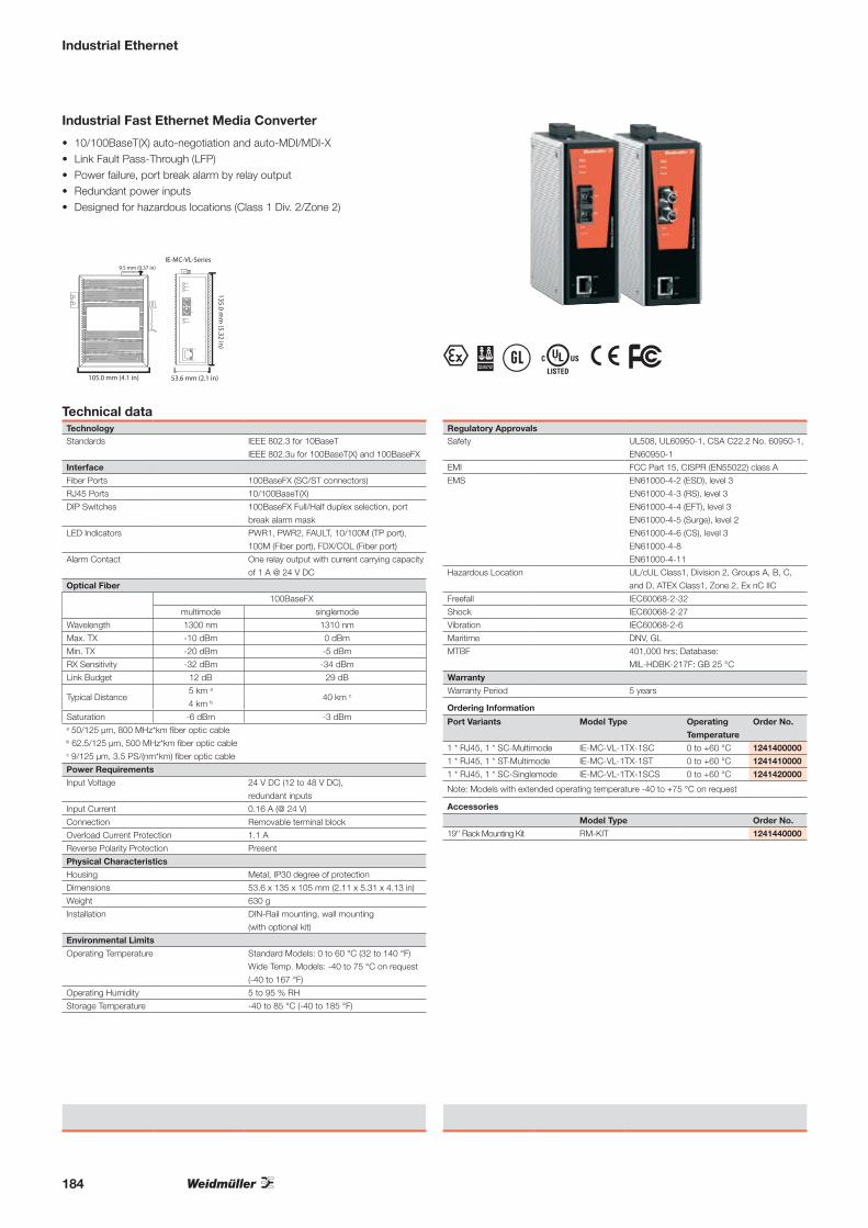
Industrial Ethernet
Industrial Fast Ethernet Media Converter
• 10/100BaseT(X) auto-negotiation and auto-MDI/MDI-X• Link Fault Pass-Through (LFP)• Power failure, port break alarm by relay output• Redundant power inputs• Designed for hazardous locations (Class 1 Div. 2/Zone 2)
Technical dataTechnologyStandards IEEE 802.3 for 10BaseT
IEEE 802.3u for 100BaseT(X) and 100BaseFX
Interface
Fiber Ports 100BaseFX (SC/ST connectors)
RJ45 Ports 10/100BaseT(X)
DIP Switches 100BaseFX Full/Half duplex selection, port
break alarm mask
LED Indicators PWR1, PWR2, FAULT, 10/100M (TP port),
100M (Fiber port), FDX/COL (Fiber port)
Alarm Contact One relay output with current carrying capacity
of 1 A @ 24 V DC
Optical Fiber
100BaseFX
multimode singlemode
Wavelength 1300 nm 1310 nm
Max. TX -10 dBm 0 dBm
Min. TX -20 dBm -5 dBm
RX Sensitivity -32 dBm -34 dBm
Link Budget 12 dB 29 dB
Typical Distance5 km a
4 km b40 km c
Saturation -6 dBm -3 dBma 50/125 μm, 800 MHz*km fiber optic cableb 62.5/125 μm, 500 MHz*km fiber optic cablec 9/125 μm, 3.5 PS/(nm*km) fiber optic cable
Power Requirements
Input Voltage 24 V DC (12 to 48 V DC),
redundant inputs
Input Current 0.16 A (@ 24 V)
Connection Removable terminal block
Overload Current Protection 1.1 A
Reverse Polarity Protection Present
Physical Characteristics
Housing Metal, IP30 degree of protection
Dimensions 53.6 x 135 x 105 mm (2.11 x 5.31 x 4.13 in)
Weight 630 g
Installation DIN-Rail mounting, wall mounting
(with optional kit)
Environmental Limits
Operating Temperature Standard Models: 0 to 60 °C (32 to 140 °F)
Wide Temp. Models: -40 to 75 °C on request
(-40 to 167 °F)
Operating Humidity 5 to 95 % RH
Storage Temperature -40 to 85 °C (-40 to 185 °F)
Regulatory ApprovalsSafety UL508, UL60950-1, CSA C22.2 No. 60950-1,
EN60950-1
EMI FCC Part 15, CISPR (EN55022) class A
EMS EN61000-4-2 (ESD), level 3
EN61000-4-3 (RS), level 3
EN61000-4-4 (EFT), level 3
EN61000-4-5 (Surge), level 2
EN61000-4-6 (CS), level 3
EN61000-4-8
EN61000-4-11
Hazardous Location UL/cUL Class1, Division 2, Groups A, B, C,
and D, ATEX Class1, Zone 2, Ex nC IIC
Freefall IEC60068-2-32
Shock IEC60068-2-27
Vibration IEC60068-2-6
Maritime DNV, GL
MTBF 401,000 hrs; Database:
MIL-HDBK-217F: GB 25 °C
Warranty
Warranty Period 5 years
T ; u \ %
135.0 mm
(5.32 in)
9.5 mm (0.37 in)
105.0 mm (4.1 in) 53.6 mm (2.1 in)
IE-MC-VL-Series
Ordering Information
Port Variants Model Type Operating
Temperature
Order No.
1 * RJ45, 1 * SC-Multimode IE-MC-VL-1TX-1SC 0 to +60 °C 1241400000
1 * RJ45, 1 * ST-Multimode IE-MC-VL-1TX-1ST 0 to +60 °C 1241410000
1 * RJ45, 1 * SC-Singlemode IE-MC-VL-1TX-1SCS 0 to +60 °C 1241420000
Note: Models with extended operating temperature -40 to +75 °C on request
Accessories
Model Type Order No.
19'' Rack Mounting Kit RM-KIT 1241440000
184

Industrial Ethernet
1 and 2- port Serial/Ethernet Converter for industrial automation
• Enhanced surge protection for serial, LAN, and power• Rugged screw-type terminal blocks for power and serial connectors • Cascading Ethernet ports for easy wiring • Redundant DC power inputs • Warning by relay output and email • Low power consumption
Technical dataEthernet InterfaceNumber of Ports 2
Speed 10/100 Mbps, auto MDI/MDIX
Connector 8-pin RJ45
Magnetic Isolation Protection 1.5 KV built-in
Ethernet Line Protection 1 KV (level 2) surge protection
Serial Interface
Number of Ports IE-CS-2TX-1RS232/485: 1
IE-CS-2TX-2RS232/485: 2
Serial Standards RS-232/422/485
Connector IE-CS-2TX-1RS232/485: DB9 for RS-232,
terminal block for RS-422/485
IE-CS-2TX-2RS232/485: DB9 for
RS-232/422/485
Serial Line Protection • 15 KV ESD protection for all signals
• 1 KV (level 2) surge protection
RS-485 Data Direction Control ADDC® (automatic data direction control)
Serial Communication Parameters
Data Bits 5, 6, 7, 8
Stop Bits 1, 1.5, 2
Parity None, Even, Odd, Space, Mark
Flow Control RTS/CTS and DTR/DSR (RS-232 only),
XON/XOFF
Baud rate 50 to 921.6 Kbps
Serial Signals
RS-232 TxD, RxD, RTS, CTS, DTR, DSR, DCD, GND
RS-422 Tx+, Tx-, Rx+, Rx-, GND
RS-485-4w Tx+, Tx-, Rx+, Rx-, GND
RS-485-2w Data+, Data-, GND
Software
Network Protocols ICMP, IP, TCP, UDP, DHCP, BOOTP, Telnet,
Rtelnet, DNS, SNMP, HTTP, SMTP, SNTP, IGMP
Configuration Options Web Console, Serial Console, Telnet Console,
Windows Utility
Windows Real COM Drivers Windows 95/98/ME/NT/2000, Windows
XP/2003/Vista/2008/7 x86/x64
Fixed TTY Drivers SCO Unix, SCO OpenServer, UnixWare 7,
UnixWare 2.1, SVR 4.2, QNX 4.25, QNX 6,
Solaris 10, FreeBSD, AIX 5.x, HP-UX 11i
Linux Real TTY Drivers Linux kernel 2.4.x, 2.6.x
Physical Characteristics
Housing Metal, IP30 degree of protection
Weight IE-CS-2TX-1RS232/485: 475 g
IE-CS-2TX-2RS232/485: 485 g
Dimensions 36 x 105 x 140 mm (1.42 x 4.13 x 5.51 in)
Environmental Limits
Operating Temperature 0 to 60 °C (32 to 140 °F)
Operating Humidity 5 to 95% RH
Storage Temperature -40 to 85 °C (-40 to 185 °F)
Power Requirements
Input Voltage 12 to 48 V DC
Power Consumption IE-CS-2TX-1RS232/485: 12 to 48 V DC;
220 mA @ 12 V DC, 110 mA @ 24 V DC
IE-CS-2TX-2RS232/485: 12 to 48 V DC;
250 mA @ 12 V DC, 125 mA @ 24 V DC
Regulatory ApprovalsEMC CE (EN55022 Class A, EN55024), FCC Part 15
Subpart B Class A
Safety UL508
Hazardous Location UL/cUL Class 1 Division 2 Groups A, B, C
and D
ATEX Class I, Zone 2 (Pending)
EMS EN61000-4-2 (ESD), Level 3
EN61000-4-3 (RS), Level 3
EN61000-4-4 (EFT), Level 4
EN61000-4-5 (Surge), Level 3
EN61000-4-6 (CS), Level 3
EN61000-4-8
EN61000-4-11
Shock IEC60068-2-27
Freefall IEC60068-2-32
Vibration IEC60068-2-6
Reliability
Alert Tools Built-in buzzer and RTC (real-time clock)
Automatic Reboot Trigger Built-in WDT (watchdog timer)
Warranty
Warranty Period 5 years
Pin Assignment
RS-232/422/485
DB9 male port
PIN RS-232 RS-422/RS-485-4w RS-485-2W
1 DCD TxD-(A) -
1 2 3 4 5
6 7 8 9
2 RXD TxD+(B) -
3 TXD RxD+(B) Data+(B)
4 DTR RxD-(A) Data-(A)
5 GND GND GND
6 DSR - -
7 RTS - -
8 CTS - -
Pin Assignment
RS-422/485 Terminal
Block Wiring
PIN RS-422/RS-485-4w RS-485-2w
1 TxD+(B) -
1 2 3 4 5
2 TxD-(A) -
3 RxD+(B) Data+(B)
4 RxD-(A) Data-(A)
5 GND GND
Ordering Information
Models Model Type Operating
Temperature
Order No.
2x RJ45; 1x RS-232; 1x RS-422/485 IE-CS-2TX-1RS232/485 0 to +60 °C 1242080000
2x RJ45; 2x RS-232/422/485 IE-CS-2TX-2RS232/485 0 to +60 °C 1242090000
Accessories
Model Type Order No.
19" Rack Mounting Kit RM-KIT 1241440000
105 mm (4.14 in) 8.8 mm (0.35 in)
140 mm
(5.51 in)
36 mm (1.42 in)
149 mm
(5.87 in)
% \
185

Industrial Ethernet plug-in connector
Plug PushPull V4 - RJ45
Technical data
Category
Degree of protection
Housing main material
Sheath diameter, min. / max.
Plugging cycles
Ambient temperature (operational), min. / max.
Wire cross-section, flexible, min. / max.
Wire cross-section, flexible, min. / max.
Wire cross-section, solid, min. / max.
Wire cross-section, solid, min. / max.
Connector standard
Note
Ordering data - Sets
RJ45 tool-free, AWG 26-22, TIA-A/-B/-PROFINET
RJ45 tool-free, AWG 26-22, TIA-B
RJ45 Crimp, AWG 27-24
Note
With kink prevention
Cat.6A / Class EA (ISO/IEC 11801 2010)
IP 67
PA UL 94 V0
5 mm / 10 mm
750
-40 °C...+70 °C
AWG 27 / AWG 24
0.46 mm / 0.61 mm
AWG 24 / AWG 22
0.36 mm / 0.51 mm
IEC 61076-3-106 Var. 4, IEC 60603-7-51
Type Qty. Order No.IE-PS-V04P-RJ45-FH-BP 10 1963170000
IE-PS-V04P-RJ45-TH-BP 10 1963190000
Ordering data - Empty housings
Note
Type Qty. Order No.IE-PH-V04P-BP 10 1962530000
AccessoriesType Qty. Order No.IE-CR-IP67-WS20-BU 10 1963020000
IE-CR-IP67-WS20-OG 10 1963010000
IE-CR-IP67-WS20-GN 10 1963040000
IE-CR-IP67-WS20-GY 10 1963000000
IE-CR-IP67-WS20-WH 10 1962990000
IE-CR-IP67-WS20-YE 10 1963030000
IE-PP-V04P 10 1963890000
Colour codingblue
orange
green
grey
white
yellow
Dust protection cap
Plug housing protective cap
Without kink prevention
Cat.6A / Class EA (ISO/IEC 11801 2010)
IP 67
PA UL 94 V0
5 mm / 10 mm
750
-40 °C...+70 °C
AWG 27 / AWG 24
0.46 mm / 0.61 mm
AWG 24 / AWG 22
0.36 mm / 0.51 mm
IEC 61076-3-106 Var. 4, IEC 60603-7-51
Type Qty. Order No.IE-PS-V04P-RJ45-FH 10 1963160000
IE-PS-V04P-RJ45-FH-B 10 1271240000
IE-PS-V04P-RJ45-TH 10 1963180000
Type Qty. Order No.IE-PH-V04P 10 1962520000
Type Qty. Order No.IE-CR-IP67-WS20-BU 10 1963020000
IE-CR-IP67-WS20-OG 10 1963010000
IE-CR-IP67-WS20-GN 10 1963040000
IE-CR-IP67-WS20-GY 10 1963000000
IE-CR-IP67-WS20-WH 10 1962990000
IE-CR-IP67-WS20-YE 10 1963030000
IE-PP-V04P 10 1963890000
186
187
Contents
Index
Index
Index Type 188
Index Order No. 191
Addresses worldwide 194

188
Type Order No. Page Type Order No. Page Type Order No. Page Type Order No. Page
AADP WF10/WF12 1780940000 107ADP WF6/WF8 1780930000 106AIE MULTI-STRIPAX PV 1204280000 18AM 16 9204190000 147AMF 6/10 9204180000 147
BBUGH BOX WM4 1243000000 14BUGH WM4 VPE100 1217960000 14BUGH WM4 VPE500 1217940000 14BUKO WM4 VPE100 1217760000 14BUKO WM4 VPE1500 1217750000 14
CCC 15/17 K MC NE GE 1131920000 134CC 15/17 K MC NE GR 1079540000 134CC 15/17 K MC NEUTR. SI 1876580000 134CC 15/17 K MC NEUTR. WS 1876590000 134CC 15/17 K MC SONDERD. 1876600000 134CC 15/17 MC NE GE 1131930000 134CC 15/17 MC NE GR 1079530000 134CC 15/17 MC NEUTRAL SI 1876610000 134CC 15/17 MC NEUTRAL WS 1876570000 134CC 15/17 MC SONDERD. 1876620000 134CC 15/27 K MC NE GE 1131910000 134CC 15/27 K MC NE GR 1079560000 134CC 15/27 K MC NEUTR. SI 1876780000 134CC 15/27 K MC NEUTR. WS 1876640000 134CC 15/27 K MC SONDERD. 1876750000 134CC 15/27 MC NE GE 1131940000 134CC 15/27 MC NE GR 1079550000 134CC 15/27 MC NEUTRAL SI 1876760000 134CC 15/27 MC NEUTRAL WS 1876770000 134CC 15/27 MC SONDERD. 1876630000 134CC 15/45 K MC NE GE 1111260000 134CC 15/45 K MC NE GR 1111270000 134CC 15/45 K MC NE WS 1111250000 134CC 15/45 K MC SDR 1111200000 134CC 15/45 MC NE GE 1111230000 134CC 15/45 MC NE GR 1111240000 134CC 15/45 MC NE WS 1111210000 134CC 15/45 MC SDR 1111190000 134CC 15/49 K MC NE GE 1131970000 134CC 15/49 K MC NE GR 1079580000 134CC 15/49 K MC NEUTR. SI 1877270000 134CC 15/49 K MC NEUTR. WS 1877220000 134CC 15/49 K MC SONDERD. 1877230000 134CC 15/49 MC NE GE 1076970000 134CC 15/49 MC NE GR 1079570000 134CC 15/49 MC NEUTRAL SI 1877240000 134CC 15/49 MC NEUTRAL WS 1877260000 134CC 15/49 MC SONDERD. 1877200000 134CC 15/60 K MC NE GE 1131890000 134CC 15/60 K MC NE GR 1072650000 134CC 15/60 K MC NEUTR. SI 1877360000 134CC 15/60 K MC NEUTR. WS 1877310000 134CC 15/60 K MC SONDERD. 1877320000 134CC 15/60 MC NE GE 1131960000 134CC 15/60 MC NE GR 1072640000 134CC 15/60 MC NEUTRAL SI 1877340000 134CC 15/60 MC NEUTRAL WS 1877350000 134CC 15/60 MC SONDERD. 1877300000 134CC 30/60 K MC NE GE 1078320000 134CC 30/60 K MC NE GR 1072680000 134CC 30/60 K MC NE RT 1085430000 134CC 30/60 K MC NEUTRAL SI 1934330000 134CC 30/60 K MC NEUTRAL WS 1934390000 134CC 30/60 K MC SONDERDRUCK 1934370000 134CC 30/60 MC NE GE 1009320000 134CC 30/60 MC NE GR 1072670000 134CC 30/60 MC NEUTRAL SI 1934400000 134CC 30/60 MC NEUTRAL WS 1934420000 134CC 30/60 MC SONDERDRUCK 1934410000 134CC 85/54 K MC NE GE 1138440000 134CC 85/54 K MC NE GR 1138450000 134CC 85/54 K MC NE WS 1138430000 134CC 85/54 K MC SDR 1138470000 134CC 85/54 MC NE GE 1138410000 134CC 85/54 MC NE GR 1138420000 134CC 85/54 MC NE WS 1138400000 134CC 85/54 MC SDR 1138460000 134CP M SNT 1000W 24V 40A 8951380000 121CP M SNT 120W 24V 5A 8951340000 119CP M SNT 180W 24V 7,5A 8951350000 120CP M SNT 250W 24V 10A 8951360000 120CP M SNT 500W 24V 20A 8951370000 121CP M SNT 70W 24V 3A 8951330000 119CP M SNT3 1000W 24V 40A 8951420000 123CP M SNT3 120W 24V 5A 8951390000 122CP M SNT3 250W 24V 10A 8951400000 122CP M SNT3 500W 24V 20A 8951410000 123CP SNT 24W 12V 1.5A 9928890012 124CP SNT 24W 24V 1A 9928890024 124CP SNT 24W 5V 2A 9928890005 125CP SNT 25W 5V 5A 8754960000 126CP SNT 48W 12V 4A 8754970000 127
CP SNT 48W 24V 2A 8739140000 128CP SNT 48W 48V 1A 8879230000 129CTF PV WM4 1222870000 19CTI 6 9006120000 152CTI 6 G 9202850000 152CTN 25 D4 9006220000 153CTN 25 D5 9006230000 153CTX PV 1249710000 19
DDEK 5 BL NEUTRAL 0473391693 132DEK 5 BR NEUTRAL 0473391692 132DEK 5 FSZ 1-10 0460660001 132DEK 5 FSZ 11-20 0460660011 132DEK 5 GE NEUTRAL 0473391687 132DEK 5 GN NEUTRAL 0473391688 132DEK 5 GR NEUTRAL 0473391691 132DEK 5 GW - 0576261199 132DEK 5 GW + 0576261198 132DEK 5 GW 1 0522660001 132DEK 5 GW 10 0522660010 132DEK 5 GW 11 0522660011 132DEK 5 GW 12 0522660012 132DEK 5 GW 13 0522660013 132DEK 5 GW 14 0522660014 132DEK 5 GW 15 0522660015 132DEK 5 GW 16 0522660016 132DEK 5 GW 17 0522660017 132DEK 5 GW 18 0522660018 132DEK 5 GW 19 0522660019 132DEK 5 GW 2 0522660002 132DEK 5 GW 20 0522660020 132DEK 5 GW 3 0522660003 132DEK 5 GW 4 0522660004 132DEK 5 GW 5 0522660005 132DEK 5 GW 6 0522660006 132DEK 5 GW 7 0522660007 132DEK 5 GW 8 0522660008 132DEK 5 GW 9 0522660009 132DEK 5 GW ERDE 0576261202 132DEK 5 GW ERDE I.KR. 0576261203 132DEK 5 GW L1 0522361075 132DEK 5 GW L2 0522361076 132DEK 5 GW L3 0522361077 132DEK 5 NEUTRAL 0473360000 132DEK 5 OR NEUTRAL 0473391690 132DEK 5 RT NEUTRAL 0473391686 132DEK 5 SW NEUTRAL 0473391694 132DEK 5 VI NEUTRAL 0473391689 132DEK 6 NEUTRAL 0468560000 105DMSI MANUELL 0,5-1,7 9918390000 154DMSI MANUELL 2,0-8,0 9918400000 154
EEBR-MODULE RS232 1241430000 182EMC-CONTACT 1067520000 79EMC-SET 1067470000 79EMC-TIE 1067490000 79ERAN MULTI-STRIPAX 9203100000 18ERME 10² SPX 4 1119030000 146ERME 16² SPX 4 1119040000 146ERME AM 16 9204260000 147ERME AMF 6/10 9204250000 147ERME MULTI-STRIPAX 9203070000 18ESG 6/15 K MC NEUTR. WS 1880100000 88EW 15 0382860000 113EW 15/2 1071900000 113EW 35 0383560000 113EW 35 DB 1269050000 113EW 35 GR 7032 0383530000 113EWK 1 0206160000 113EWK 2 0199360000 113
FFUSE 1KV DC 10A 10/38 1224910000 89FUSE 1KV DC 12A 10/38 1224920000 89FUSE 1KV DC 16A 10/38 1224930000 89FUSE 1KV DC 20A 10/38 1224950000 89FUSE 1KV DC 2A 10/38 1224870000 89FUSE 1KV DC 4A 10/38 1224880000 89FUSE 1KV DC 6A 10/38 1224890000 89FUSE 1KV DC 8A 10/38 1224900000 89
HH0,14/10 GR SV 9005180000 158H0,14/12 GR SV 9028240000 158H0,25/10 HBL 9025740000 158H0,25/10 HBL SV 9026050000 158H0,25/12 HBL 9025760000 158H0,25/12 HBL SV 9025780000 158H0,34/10 TK 9025750000 158H0,34/10 TK SV 9026030000 158H0,34/12 TK 9025770000 158H0,34/12 TK SV 9025790000 158H0,5/12 OR 0409500000 158H0,5/12 OR SV 9028260000 158
H0,5/14 OR 0690700000 158H0,5/14 OR SV 9026060000 158H0,5/16 OR 9025870000 158H0,5/16 OR SV 9028270000 158H0,75/12 W 0409600000 158H0,75/12 W SV 9028280000 158H0,75/14 W 0462900000 158H0,75/14 W SV 9026070000 158H0,75/16 W 9025860000 158H0,75/16 W SV 9028290000 158H0,75/18 W 9025910000 158H0,75/18 W SV 9028300000 158H1,0/12 GE 0409700000 158H1,0/12 GE SV 9028310000 158H1,0/14 GE 0463000000 158H1,0/14 GE SV 9026080000 158H1,0/16 GE 9025950000 158H1,0/16 GE SV 9028320000 158H1,0/18 GE 9025930000 158H1,0/18 GE SV 9028340000 158H1,5/14 R 0463100000 158H1,5/14 R SV 9026090000 158H1,5/16 R 0635100000 158H1,5/16 R SV 9028350000 158H1,5/24 R 0565600000 158H10,0/22 EB 0534200000 158H10,0/28 EB 0565800000 158H120,0/50 BL 9028220000 158H150,0/54 GE 9028230000 158H16,0/22 GN 0565900000 158H16,0/28 GN 0566000000 158H2,5/15 BL SV 9026100000 158H2,5/15D BL 9019160000 158H2,5/19D BL 9019170000 158H2,5/25D BL 9019180000 158H25,0/30 BR 0317000000 158H25,0/36 BR 0317100000 158H35,0/30 BE 0317200000 158H35,0/39 BE 0317300000 158H4,0/18 GR SV 9026010000 158H4,0/18D GR 9019190000 158H4,0/20D GR 9019200000 158H4,0/26D GR 9019210000 158H50/36 OLIV 0444200000 158H6,0/20 SW 0533500000 158H6,0/26 SW 0565700000 158H70,0/37 GE 9028200000 158H95,0/44 R 9028210000 158HA ADP WF6/WF10 1781050000 106HTI 15 9014400000 151HTN 21 9014610000 151HTN 21 M. AN 9014100000 151
IIE-CR-IP67-WS20-BU 1963020000 186IE-CR-IP67-WS20-GN 1963040000 186IE-CR-IP67-WS20-GY 1963000000 186IE-CR-IP67-WS20-OG 1963010000 186IE-CR-IP67-WS20-WH 1962990000 186IE-CR-IP67-WS20-YE 1963030000 186IE-CS-2TX-1RS232/485 1242080000 185IE-CS-2TX-2RS232/485 1242090000 185IE-MC-VL-1TX-1SC 1241400000 184IE-MC-VL-1TX-1SCS 1241420000 184IE-MC-VL-1TX-1ST 1241410000 184IE-NM-WMNETMANAGER 1242120000 182IE-PH-V04P 1962520000 186IE-PH-V04P-BP 1962530000 186IE-PP-V04P 1963890000 186IE-PS-V04P-RJ45-FH 1963160000 186IE-PS-V04P-RJ45-FH-B 1271240000 186IE-PS-V04P-RJ45-FH-BP 1963170000 186IE-PS-V04P-RJ45-TH 1963180000 186IE-PS-V04P-RJ45-TH-BP 1963190000 186IE-SW-BL05-4TX-1SC 1240890000 180IE-SW-BL05-4TX-1SCS 1240870000 180IE-SW-BL05-4TX-1ST 1240880000 180IE-SW-BL05-5TX 1240840000 180IE-SW-BL05T-5TX 1240850000 180IE-SW-BL08-6TX-2SC 1240910000 180IE-SW-BL08-6TX-2ST 1240930000 180IE-SW-BL08-7TX-1SCS 1240950000 180IE-SW-BL08-8TX 1240900000 180IE-SW-BL08T-6TX-2SC 1240920000 180IE-SW-PL08M-6TX-2SC 1241070000 183IE-SW-PL08M-6TX-2SCS 1241090000 183IE-SW-PL08M-6TX-2ST 1241080000 183IE-SW-PL08M-8TX 1241040000 183IE-SW-PL16M-14TX-2SC 1241120000 183IE-SW-PL16M-14TX-2ST 1241130000 183IE-SW-PL16M-16TX 1241100000 183IE-SW-VL08MT-5TX-3SC 1240970000 182IE-SW-VL08MT-6TX-2SCS 1241020000 182IE-SW-VL08MT-6TX-2ST 1240990000 182IE-SW-VL08MT-8TX 1240940000 182IE-SW-VL09T-6TX-3SC 1240980000 181IE-SW-VL16-14TX-2SC 1241030000 181IE-SW-VL16-14TX-2ST 1241050000 181IE-SW-VL16-16TX 1241000000 181
KKABELBINDERZANGE RT-1 1296000000 79KLTR ZDU6-2/D 1121050000 105KT 12 9002660000 144KT 14 1157820000 145KT 20 9002300000 145KT 22 1157830000 144KT 8 9002650000 144
LLM MT300 15X9 GE 1882890000 112LU 10.16/02/90 4.5SN BK BX 1934140000 166LU 10.16/03/90 4.5SN BK BX 1921450000 166LU 10.16/04/90 4.5SN BK BX 1226220000 166LU 10.16/05/90 4.5SN BK BX 1226230000 166LU 10.16/06/90 4.5SN BK BX 1226240000 166LU 10.16/07/90 4.5SN BK BX 1226250000 166LU 10.16/08/90 4.5SN BK BX 1226260000 166LU 10.16/09/90 4.5SN BK BX 1226270000 166LU 10.16/10/90 4.5SN BK BX 1226280000 166LUP 10.16/02/90 3.2SN BK BX 1226290000 167LUP 10.16/02/90V 3.2SN BK BX 1192980000 168LUP 10.16/03/90 3.2SN BK BX 1226300000 167LUP 10.16/03/90V 3.2SN BK BX 1192990000 168LUP 10.16/04/90 3.2SN BK BX 1226310000 167LUP 10.16/04/90V 3.2SN BK BX 1193000000 168LUP 10.16/05/90 3.2SN BK BX 1226320000 167LUP 10.16/05/90V 3.2SN BK BX 1193010000 168LUP 10.16/06/90 3.2SN BK BX 1226330000 167LUP 10.16/06/90V 3.2SN BK BX 1193020000 168LUP 10.16/07/90 3.2SN BK BX 1226340000 167LUP 10.16/07/90V 3.2SN BK BX 1193030000 168LUP 10.16/08/90 3.2SN BK BX 1226350000 167LUP 10.16/08/90V 3.2SN BK BX 1193040000 168LUP 10.16/09/90 3.2SN BK BX 1226360000 167LUP 10.16/09/90V 3.2SN BK BX 1193050000 168LUP 12.70/02/90 3.2SN BK BX 1226370000 169LUP 12.70/03/90 3.2SN BK BX 1226380000 169LUP 12.70/04/90 3.2SN BK BX 1226390000 169LUP 12.70/05/90 3.2SN BK BX 1226410000 169LUP 12.70/06/90 3.2SN BK BX 1226420000 169LUP 12.70/07/90 3.2SN BK BX 1226430000 169LUP 12.70/08/90 3.2SN BK BX 1226440000 169LUP 12.70/09/90 3.2SN BK BX 1226450000 169LX 15.00/01/90 4.5SN BK BX 1226460000 170LX 15.00/02/90 4.5SN BK BX 1226470000 170LX 15.00/03/90 4.5SN BK BX 1174720000 170LX 15.00/04/90 4.5SN BK BX 1226480000 170LX 15.00/05/90 4.5SN BK BX 1226490000 170LX 15.00/06/90 4.5SN BK BX 1226500000 170LX 15.00/07/90 4.5SN BK BX 1226510000 170LX 15.00/08/90 4.5SN BK BX 1921480000 170LXB 15.00/02/90 4.5SN BK BX 1226520000 171LXB 15.00/03/90 4.5SN BK BX 1226530000 171LXB 15.00/04/90 4.5SN BK BX 1226540000 171LXB 15.00/05/90 4.5SN BK BX 1226550000 171LXB 15.00/06/90 4.5SN BK BX 1226560000 171LXB 15.00/07/90 4.5SN BK BX 1226570000 171LXB 15.00/08/90 4.5SN BK BX 1226580000 171LXBL 15.00/01/90 4.5SN BK BX 1226590000 171LXXX 15.00/01/90 4.5SN BK BX 1047120000 172LXXX 15.00/01/90F 4.5SN BK BX 1047280000 173LXXX 15.00/01/90FL 4.5SN BK BX 1047440000 173LXXX 15.00/01/90FR 4.5SN BK BX 1047600000 173LXXX 15.00/02/90 4.5SN BK BX 1047130000 172LXXX 15.00/02/90F 4.5SN BK BX 1047290000 173LXXX 15.00/02/90FL 4.5SN BK BX 1047450000 173LXXX 15.00/02/90FR 4.5SN BK BX 1047610000 173LXXX 15.00/03/90 4.5SN BK BX 1047140000 172LXXX 15.00/03/90F 4.5SN BK BX 1047300000 173LXXX 15.00/03/90FL 4.5SN BK BX 1047460000 173LXXX 15.00/03/90FR 4.5SN BK BX 1047620000 173LXXX 15.00/04/90 4.5SN BK BX 1047150000 172LXXX 15.00/04/90F 4.5SN BK BX 1047310000 173LXXX 15.00/04/90FL 4.5SN BK BX 1047470000 173LXXX 15.00/04/90FR 4.5SN BK BX 1047630000 173
MMARKO-C. 25X25X25 B/DR. 1700530001 133MARKO-C. 50X50X50 B/DR. 1700540001 133MARKO-C.100X100X100 B/DR 1700550001 133MARKO-C.200X200X200 B/DR 1700560001 133MEW 1/32 0445600000 113MEW 35/1 1805610000 113M-PRINT PRO 1905490000 140M-PRINT PRO ADVANCED 1905500000 140MULTI-STRIPAX PV 1190490000 18MULTI-TOOL PV 1217280000 14
PPJ PRO TINTENAUFFANGWANNE 1024140000 139PJ PRO TINTENSET FARBE 1027110000 139PJ PRO TNTK INK C 1027050000 139PJ PRO TNTK INK K 1027040000 139PJ PRO TNTK INK M 1027060000 139PJ PRO TNTK INK Y 1027070000 139
189
Type Order No. Page Type Order No. Page Type Order No. Page Type Order No. Page
PRINTJET PRO 115V 1024050000 139PRINTJET PRO 230V 1001180001 139PS 2.0 MC 0310000000 105PU I 1+1 280V/12,5kA 8859100000 65PU I 1+1 LCF 260V/30KA 1266670000 68PU I 1+1R 280V/12,5kA 8859110000 65PU I 1+1R LCF 280V/30KA 1266680000 68PU I 3 280V/12,5kA 8858990000 65PU I 3 LCF 280V/30KA 1266600000 69PU I 3 R 280V/12,5kA 8859010000 65PU I 3 R LCF 280V/30KA 1266610000 69PU I 3+1 280V/12,5kA 8859080000 64PU I 3+1 LCF 280V/30KA 1266640000 68PU I 3+1R 280V/12,5kA 8859090000 64PU I 3+1R LCF 280V/30KA 1266650000 68PU II 1+1 280V/40kA 8859730000 66PU II 1+1R 280V/40kA 8859740000 66PU II 2+1 1000V DC 8882340001 62PU II 2+1R 1000V DC 8882350001 62PU II 3 1000VDC PV 1301680000 63PU II 3 280V/40kA 8859630000 67PU II 3 R 1000VDC PV 1301690000 63PU II 3 R 280V/40kA 8859650000 67PU II 3+1 280V/40kA 8859710000 66PU II 3+1R 280V/40kA 8859720000 66PV AC 1IN 3P SW 230/32/300mA SPD CG 7504814001 55PV AC 1IN SW 230/16/300mA SPD CG 7504812002 53PV AC 1IN SW 230/16/30mA SPD CG 7504812007 52PV AC 1IN SW 230/20/300mA SPD CG 7504812003 54PV AC 1IN SW 230/20/30mA SPD CG 7504812008 52PV AC 1IN SW 230/25/300mA SPD CG 7504812006 54PV AC 1IN SW 230/25/30mA SPD CG 7504812005 53PV AC 1IN SW 230/32/300mA SPD CG 7504812004 55PV AC 1IN SW 230/32/30mA SPD CG 7504812009 53PV DC 12IN SW FH SPD CG 1000V 7504813010 50PV DC 14IN SW FH SPD CG 14i+ 1000V 7504813003 51PV DC 16IN SW FH SPD CG 1000V 7504813011 51PV DC 16IN SW FH SPD CG 2x8i+ 1000V 7504813004 51PV DC 1IN SPD CG 1000V 7504811010 44PV DC 1IN SPD WM4 1000V 7504811001 44PV DC 1INx2 2MMPT 2SPD WM4 1000V 7504811002 45PV DC 1INx2 2MPPT 2SPD CG 1000V 7504811011 45PV DC 2INx2 2SW 2MPPT 2SPD CG 1000V 7504811012 45PV DC 2INx3 3SW 3MPPT 3SPD CG 1000V 7504811013 46PV DC 3IN SPD CG 1000V 7504811014 46PV DC 3IN SPD WM4 1000V 7504811005 47PV DC 3IN SW SPD CG 1000V 7504811015 47PV DC 3IN SW SPD WM4 600V 7504811006 47PV DC 4+2IN 2SW 2MPPT FH 2SPD CG 1000V 7504813008 49PV DC 4IN SW FH SPD CG 1000V 7504811016 48PV DC 4IN SW FH SPD CG 4i+ 1000V 7504811009 48PV DC 4IN SW FH SPD WM4 1000V 7504811007 49PV DC 8IN SW FH SPD CG 1000V 7504813009 49PV DC 8IN SW FH SPD CG 8i+ 1000V 7504813002 50PV SET WM4 1257780000 18PV-BOX D6.0 ES 1110210000 8PZ 16 9012600000 149PZ 3 0567300000 148PZ 50 9006450000 150PZ 6 Roto 9014350000 148PZ ZH 16 9013600000 149
RRECLINIC USB 1175040000 26RM-KIT 1241440000 180RM-KIT 1241440000 182RM-KIT 1241440000 184
SSD 0,6x3,5x100 9008330000 100SD 0,8x4,0x100 9008340000 101SD 1,0x5,5x150 9008350000 92SD 1,2x6,5x150 9009010000 102SDI 0,4x2,5x75 9008370000 155SDI 0,5x3,0x100 9008380000 155SDI 0,6x3,5x100 9008390000 155SDI 0,8x4,0x100 9008400000 155SDI 0.4X2.0X60 9205690000 155SDI 1,0x4,5x125 9008910000 155SDI 1,0x5,5x125 9008410000 155SDI 1,2x6,5x150 9008420000 155SDI 1,6x8,0x175 9008430000 155SDI 1.0X4.5X175 9205700000 155SDI 1.0X5.5X175 9205710000 155SDI SL 0,6X3,5X100 1274660000 156SDI SL 0,8X4,0X100 1274670000 156SDI SL 1,0X5,5X125 1274680000 156SDI SL 1,2X6,5X150 1274690000 156SDIK PH0 9008560000 155SDIK PH1 9008570000 155SDIK PH2 9008580000 155SDIK PH3 9008590000 155SDIK PZ1 9008900000 155SDIK PZ2 9008890000 155SDIK SL PH1 1274710000 156SDIK SL PH2 1274720000 156SDIK SL PZ1 1274730000 156SDIK SL PZ2 1274740000 156
SDIS 2,5-5,5/PH1/2 9009730000 157SDIS 2.0-5.5 9205550000 157SDIS 2.5-5.5/PZ/1/2 1128540000 157SDIS SL 3,5-6,5/PH/1/2 1274750000 156SDIZ 0,8X5,5 150/248 9008640000 155SDIZ 0.6X3.5X100 9008450000 155SDIZ 0.8X4.0X100 9008460000 155SF 0/12 NEUTRAL BL V2 1919220000 136SF 0/12 NEUTRAL GE V2 1919210000 136SF 0/12 NEUTRAL RT V2 1919230000 136SF 0/12 NEUTRAL WS V2 1919240000 136SF 0/12 SONDERDRUCK V2 1919250000 136SF 0/21 NEUTRAL BL V2 1918510000 136SF 0/21 NEUTRAL GE V2 1918480000 136SF 0/21 NEUTRAL RT V2 1918490000 136SF 0/21 NEUTRAL WS V2 1918500000 136SF 0/21 SONDERDRUCK V2 1918470000 136SF 00/12 NEUTRAL BL V2 1919270000 136SF 00/12 NEUTRAL GE V2 1919260000 136SF 00/12 NEUTRAL RT V2 1919280000 136SF 00/12 NEUTRAL WS V2 1919290000 136SF 00/12 SONDERDRUCK V2 1919300000 136SF 00/21 NEUTRAL BL V2 1918590000 136SF 00/21 NEUTRAL GE V2 1918560000 136SF 00/21 NEUTRAL RT V2 1918570000 136SF 00/21 NEUTRAL WS V2 1918580000 136SF 00/21 SONDERDRUCK V2 1918530000 136SF 1/12 NEUTRAL BL V2 1919360000 136SF 1/12 NEUTRAL GE V2 1919340000 136SF 1/12 NEUTRAL RT V2 1919320000 136SF 1/12 NEUTRAL WS V2 1919390000 136SF 1/12 SONDERDRUCK V2 1919420000 136SF 1/21 NEUTRAL BL V2 1918620000 136SF 1/21 NEUTRAL GE V2 1918610000 136SF 1/21 NEUTRAL RT V2 1918600000 136SF 1/21 NEUTRAL WS V2 1918630000 136SF 1/21 SONDERDRUCK V2 1918640000 136SF 2/12 NEUTRAL BL V2 1919480000 136SF 2/12 NEUTRAL GE V2 1919470000 136SF 2/12 NEUTRAL RT V2 1919460000 136SF 2/12 NEUTRAL WS V2 1919490000 136SF 2/12 SONDERDRUCK V2 1919500000 136SF 2/21 NEUTRAL BL V2 1918700000 136SF 2/21 NEUTRAL GE V2 1918660000 136SF 2/21 NEUTRAL RT V2 1918670000 136SF 2/21 NEUTRAL WS V2 1918690000 136SF 2/21 SONDERDRUCK V2 1918650000 136SF 3/12 NEUTRAL BL V2 1919550000 136SF 3/12 NEUTRAL GE V2 1919520000 136SF 3/12 NEUTRAL RT V2 1919530000 136SF 3/12 NEUTRAL WS V2 1919540000 136SF 3/12 SONDERDRUCK V2 1919510000 136SF 3/21 NEUTRAL BL V2 1918920000 136SF 3/21 NEUTRAL GE V2 1918890000 136SF 3/21 NEUTRAL RT V2 1918900000 136SF 3/21 NEUTRAL WS V2 1918910000 136SF 3/21 SONDERDRUCK V2 1918880000 136SF 4.5/21 NEUTRAL BL V2 1919030000 136SF 4.5/21 NEUTRAL GE V2 1919000000 136SF 4.5/21 NEUTRAL RT V2 1919010000 136SF 4.5/21 NEUTRAL WS V2 1919020000 136SF 4.5/21 SONDERDRUCK V2 1918990000 136SF 4/12 NEUTRAL BL V2 1919590000 136SF 4/12 NEUTRAL GE V2 1919580000 136SF 4/12 NEUTRAL RT V2 1919570000 136SF 4/12 NEUTRAL WS V2 1919600000 136SF 4/12 SONDERDRUCK V2 1919610000 136SF 4/21 NEUTRAL BL V2 1919090000 136SF 4/21 NEUTRAL GE V2 1919060000 136SF 4/21 NEUTRAL RT V2 1919070000 136SF 4/21 NEUTRAL WS V2 1919080000 136SF 4/21 SONDERDRUCK V2 1919050000 136SF 5/12 NEUTRAL BL V2 1919630000 136SF 5/12 NEUTRAL GE V2 1919620000 136SF 5/12 NEUTRAL RT V2 1919640000 136SF 5/12 NEUTRAL WS V2 1919650000 136SF 5/12 SONDERDRUCK V2 1919660000 136SF 5/21 NEUTRAL BL V2 1919150000 136SF 5/21 NEUTRAL GE V2 1919120000 136SF 5/21 NEUTRAL RT V2 1919130000 136SF 5/21 NEUTRAL WS V2 1919140000 136SF 5/21 SONDERDRUCK V2 1919110000 136SF 6/21 NEUTRAL BL V2 1919200000 136SF 6/21 NEUTRAL GE V2 1919170000 136SF 6/21 NEUTRAL RT V2 1919180000 136SF 6/21 NEUTRAL WS V2 1919190000 136SF 6/21 SONDERDRUCK V2 1919160000 136SFGH BOX WM4 1242990000 14SFGH WM4 VPE100 1217850000 14SFGH WM4 VPE500 1217830000 14SFKO WM4 VPE100 1217670000 14SFKO WM4 VPE1500 1217650000 14SFX 10/23 NE BL V2 1852400000 136SFX 10/23 NE GE V2 1852360000 136SFX 10/23 NE RT V2 1852370000 136SFX 10/23 NE WS V2 1852390000 136SFX 10/23 SDR V2 1852380000 136SFX 11/60 MC NE BL 1051870000 136SFX 11/60 MC NEUTRAL GE 1860150000 136SFX 11/60 MC NEUTRAL RT 1963650000 136
SFX 11/60 MC NEUTRAL WS 1860120000 136SFX 11/60 SONDERDRUCK 1860140000 136SFX 14/23 NEUTRAL BL V2 1852450000 136SFX 14/23 NEUTRAL GE V2 1852410000 136SFX 14/23 NEUTRAL RT V2 1852420000 136SFX 14/23 NEUTRAL WS V2 1852440000 136SFX 14/23 SONDERDR. V2 1852430000 136SFX 30/60 MC NE GE 1083240000 136SFX 30/60 MC NE WS 1083230000 136SFX 30/60 MC SDR 1083260000 136SFX 9/24 NE BL V2 1852500000 136SFX 9/24 NE GE V2 1852460000 136SFX 9/24 NE RT V2 1852470000 136SFX 9/24 NE WS V2 1852490000 136SFX 9/24 SDR V2 1852480000 136SKS 2,0-8,0 9008860000 112STRIPAX 9005000000 146STRIPAX 16 9005610000 146SYMBOL-P. 25X25X25 B/DR 1741090000 133SYMBOL-P. 50X50X50 B/DR 1741100000 133SYMBOL-P. 75X75X75 B/DR 1741110000 133SYMBOL-PACK 14X14 ERDE 1685690002 133SYMBOL-PACK 14X14 SYMB. 1685690001 133SYMBOL-PACK 9X19 SYMB. 1685700000 133
TTM 0/12 HF/HB 1719760000 138TM 0/18 HF/HB 1719770000 138TM 1/12 HF/HB 1719780000 138TM 1/18 HF/HB 1719790000 138TM 2/12 HF/HB 1719800000 138TM 2/18 HF/HB 1719810000 138TM 3/12 HF/HB 1719820000 138TM 3/18 HF/HB 1719830000 138TM 4/12 HF/HB 1719840000 138TM 4/18 HF/HB 1719850000 138TM 5/12 HF/HB 1719860000 138TM 5/18 HF/HB 1719870000 138TM 6/12 HF/HB 1719880000 138TM 6/18 HF/HB 1719890000 138TM-I 12 NEUTRAL BL 1718411693 138TM-I 12 NEUTRAL GE 1718411687 138TM-I 12 NEUTRAL GN 1718411688 138TM-I 12 NEUTRAL RT 1718411686 138TM-I 12 NEUTRAL WS 1718411044 138TM-I 12 SONDERDRUCK 1718420000 138TM-I 18 NEUTRAL BL 1718431693 138TM-I 18 NEUTRAL GE 1718431687 138TM-I 18 NEUTRAL GN 1718431688 138TM-I 18 NEUTRAL RT 1718431686 138TM-I 18 NEUTRAL WS 1718431044 138TM-I 18 SONDERDRUCK 1718440000 138TMX 18 HF/HB 1748820000 138TRANSCLINIC 14I+ 1238130000 32TRANSCLINIC 4I+ 1238100000 32TRANSCLINIC 7I+ 1238110000 32TRANSCLINIC 8I+ 1238120000 32TRANSCLINIC VI50 1175050000 26
VVSPC 2CL 12VDC 8924440000 75VSPC 2CL 12VDC R 8951470000 75VSPC 2CL 24VAC 8924490000 75VSPC 2CL 24VAC R 1093400000 75VSPC 2CL 24VDC 8924470000 75VSPC 2CL 24VDC R 8951480000 75VSPC 2CL 48VAC 8951490000 75VSPC 2CL 5VDC 8924400000 75VSPC 2CL 5VDC R 8951460000 75VSPC 2CL 60VAC 8951500000 75VSPC 2CL HF 12VDC 8924460000 77VSPC 2CL HF 12VDC R 8951690000 77VSPC 2CL HF 24VDC 8924510000 77VSPC 2CL HF 24VDC R 8951700000 77VSPC 2CL HF 5VDC 8924430000 77VSPC 2CL HF 5VDC R 8951680000 77VSPC BASE 2/4CH FG R 8951800000 78VSPC BASE 2/4CH R 8951790000 78VSPC BASE 2CL 8924710000 74VSPC BASE 2CL FG 8924270000 74VSPC BASE 2CL FG R 8951720000 74VSPC BASE 2CL R 8951710000 74VSPC CONTROL UNIT 24VDC 8972270000 80VSPC RS485 2CH 8924670000 79VSPC RS485 2CH R 8951670000 79VSSO WM4 1254870000 14V-TEST 8951860000 84
WWAD 12 M. BL. 1055960000 94WAD 12 NEUTRAL 1056260000 94WAD 16N GE BED 1083600000 96WAD 16N WS 1083500000 96WAD 20 GE WSD 9512260000 96WAD 20 WS 9512270000 96WAD 20 WS 9512270000 97WAD 5 M. BL. 1053460000 93
WAD 5 NEUTRAL 1056060000 93WAD 8 M. BL. 1053560000 94WAD 8 NEUTRAL 1056160000 94WAH 120 1064660000 111WAH 185/300 BE 1064760000 111WAH 35 1064460000 110WAH 70 BE 1064560000 110WAP 16+35 WTW 2.5-10 1050100000 93WAP 16+35 WTW 2.5-10 BL 1050180000 93WAP 2.5-10 1050000000 93WAP 2.5-10 BL 1050080000 93WD 1 25 K KARTE A 6 ST 1563900000 110WDU 10 1020300000 94WDU 10 BL 1020380000 94WDU 16/ZA 1028900000 94WDU 16/ZA BL 1028980000 94WDU 240 1802780000 97WDU 240 BL 1822210000 97WDU 35/IK/ZA 1029000000 95WDU 35/ZA 1028800000 95WDU 35/ZA BL 1028880000 95WDU 35N 1040400000 96WDU 35N BL 1040480000 96WDU 4 1020100000 93WDU 4 BL 1020180000 93WDU 50N 1820840000 96WDU 50N BL 1820850000 96WDU 6 1020200000 93WDU 6 BL 1020280000 93WDU 70N/35 9512190000 97WDU 70N/35 BL 9512420000 97WDU 95N/120N 1820550000 97WDU 95N/120N BL 1820560000 97WEW 32/1 1067600000 113WEW 32/1 SW 1272980000 113WEW 35/1 1059000000 94WEW 35/1 GR 1227890000 113WEW 35/1 SW 1162600000 113WEW 35/2 1061200000 93WEW 35/2 GR 7042 1859200000 113WEW 35/2 SW 1061210000 113WF 10 1780870000 107WF 10/2BZ 1789790000 109WF 12 1780880000 107WF 5 1790130000 106WF 6 1780850000 106WF 6/2BZ 1789770000 108WF 8 1780860000 107WF 8/2BZ 1789780000 108WFF 120 1028500000 111WFF 120 BL 1028580000 111WFF 120/AH 1029500000 111WFF 185 1028600000 111WFF 185 BL 1028680000 111WFF 185/AH 1029600000 111WFF 300 1028700000 111WFF 300 BL 1028780000 111WFF 300/AH 1029700000 111WFF 35 1028300000 110WFF 35 BL 1028380000 110WFF 35/AH 1029300000 110WFF 70 1028400000 110WFF 70 BL 1028480000 110WFF 70/AH 1029400000 110WK IK PH0 9918460000 154WK IK PH1 9918470000 154WK IK PH2 9918480000 154WK IK PZ0 9918490000 154WK IK PZ1 9918500000 154WK IK PZ2 9918510000 154WK SI 0,4x2,5 9918410000 154WK SI 0,5x3,0 9918420000 154WK SI 0,6x3,5 9918430000 154WK SI 0,8x4,0 9918440000 154WK SI 1,0x5,5 9918450000 154WPDB 70/16 1/10 1939460000 112WPE 10 1010300000 101WPE 16 1010400000 102WPE 35 1010500000 102WPE 35N 1717740000 103WPE 4 1010100000 100WPE 50N 1846040000 103WPE 6 1010200000 101WPE 70N/35 9512200000 103WPE 95N/120N 1846030000 104WQB 240/2 1802790000 97WQB 240/3 1802800000 97WQB-PEN 10 1060300000 101WQB-PEN 16 1060200000 102WQB-PEN 35 1060100000 102WQL 2 WF10 1781010000 107WQL 2 WF12 1781030000 107WQL 2 WF5 1812710000 106WQL 2 WF6 1780970000 106WQL 2 WF8 1780990000 107WQL 2 WFF120 1065100000 111WQL 2 WFF185 1065200000 111WQL 2 WFF300 1065300000 111WQL 2 WFF35 1064900000 110WQL 2 WFF70 1065000000 110

190
Type Order No. Page Type Order No. Page Type Order No. Page Type Order No. Page
WQL 3 WF10 1781020000 107WQL 3 WF12 1781040000 107WQL 3 WF5 1812740000 106WQL 3 WF6 1780980000 106WQL 3 WF8 1781000000 107WQL 3 WFF120 1065600000 111WQL 3 WFF185 1065700000 111WQL 3 WFF300 1065800000 111WQL 3 WFF35 1065400000 110WQL 3 WFF70 1065500000 110WQV 10/10 1052460000 94WQV 10/2 1052560000 94WQV 10/3 1054960000 94WQV 10/4 1055060000 94WQV 16/10 1053360000 94WQV 16/2 1053260000 94WQV 16/3 1055160000 94WQV 16/4 1055260000 94WQV 16N-PEN BL 1071360000 103WQV 35/10 1053160000 95WQV 35/2 1053060000 95WQV 35/3 1055360000 95WQV 35/4 1055460000 95WQV 35N/2 1079200000 96WQV 35N/3 1079300000 96WQV 35N/4 1079400000 96WQV 4/10 1052060000 93WQV 4/2 1051960000 93WQV 4/3 1054560000 93WQV 4/4 1054660000 93WQV 50N/2 1834060000 96WQV 50N/3 1834070000 96WQV 50N/4 1834080000 96WQV 6/10 1052260000 93WQV 6/2 1052360000 93WQV 6/3 1054760000 93WQV 6/4 1054860000 93WQV 70N/2 9512240000 97WQV 70N/3 9512250000 97WQV 70N/4 9531290000 97WQV 70N-PEN 9525840000 103WQV 95/120/2 1826890000 97WQV 95/120/3 1826900000 97WQV 95/120/4 1826910000 97WS 12/6 MC NEUTRAL 1609900000 105WSH 8 MT 1080400000 105WSI 25/1 10x38 1KV 1137790000 88WSI 25/1 10X38/LED 1KV 1137780000 88WTA 3 WDU4 1632350000 93WTA 3/ZA WDU4 1632360000 93WTA 5/1 1051260000 94WTW EN 1058800000 96WTW WF10/WF12 1780890000 107WTW WF10/WF12 2300 1780920000 107WTW WF6 1781220000 106WTW WF6 2300 1781230000 106WTW WF6-WF12 1781240000 106WTW WF8 1780900000 107WTW WF8 2300 1780910000 107WTW WFF120 1067300000 111WTW WFF185/300 1067400000 111WTW WFF35 1067100000 110WTW WFF70 1067200000 110
ZZAD 2/4 1609080000 105ZAD 3/4 1609120000 92ZAD 4/5 1746730000 92ZAP ZDU6-2 SW 1814710000 105ZAP/TW 10/16 1749580000 99ZAP/TW 5 1608830000 92ZAP/TW 5 BL 1608840000 92ZAP/TW ZDU10 1748660000 92ZAP/TW ZDU10 BL 1764110000 92ZAP/TW6/3AN 7907370000 98ZDU 10 1746750000 92ZDU 10 BL 1746760000 92ZDU 10/3AN 1767690000 92ZDU 10/3AN BL 1767700000 92ZDU 6 1608620000 92ZDU 6 BL 1608630000 92ZDU 6/3AN 7907410000 92ZDU 6/3AN BL 7907420000 92ZDU 6-2/D+ 1121120000 105ZEW 15 7920340000 113ZEW 35 9540000000 92ZEW 35 GR 1238040000 113ZEW 35/2 8630740000 113ZEW 35/2 GR 1227850000 113ZEW 35/2 SW 1162610000 113ZPE 10 1746770000 99ZPE 10/3AN 1767670000 99ZPE 6 1608670000 98ZPE 6/3AN 7907400000 98ZQV 10/2 1739680000 92ZQV 4N/10 GE 1758260000 93ZQV 4N/2 GE 1758250000 93ZQV 4N/20 GE 1909020000 93ZQV 4N/3 GE 1762630000 93
ZQV 4N/4 GE 1762620000 93ZQV 6/2 GE 1627850000 92ZQV 6/24 GE 1908990000 92ZQV 6/3 GE 1627860000 92ZQV 6/4 GE 1627870000 92ZTA 3 ZDU6 1654050000 92ZTA 7/ZA 1780670000 105

191
Order No. Type Page Order No. Type Page Order No. Type Page Order No. Type Page
01900000000199360000 EWK 2 113
02000000000206160000 EWK 1 113
03100000000310000000 PS 2.0 MC 1050317000000 H25,0/30 BR 1580317100000 H25,0/36 BR 1580317200000 H35,0/30 BE 1580317300000 H35,0/39 BE 158
03800000000382860000 EW 15 1130383530000 EW 35 GR 7032 1130383560000 EW 35 113
04000000000409500000 H0,5/12 OR 1580409600000 H0,75/12 W 1580409700000 H1,0/12 GE 158
04400000000444200000 H50/36 OLIV 1580445600000 MEW 1/32 113
04600000000460660001 DEK 5 FSZ 1-10 1320460660011 DEK 5 FSZ 11-20 1320462900000 H0,75/14 W 1580463000000 H1,0/14 GE 1580463100000 H1,5/14 R 1580468560000 DEK 6 NEUTRAL 105
04700000000473360000 DEK 5 NEUTRAL 1320473391686 DEK 5 RT NEUTRAL 1320473391687 DEK 5 GE NEUTRAL 1320473391688 DEK 5 GN NEUTRAL 1320473391689 DEK 5 VI NEUTRAL 1320473391690 DEK 5 OR NEUTRAL 1320473391691 DEK 5 GR NEUTRAL 1320473391692 DEK 5 BR NEUTRAL 1320473391693 DEK 5 BL NEUTRAL 1320473391694 DEK 5 SW NEUTRAL 132
05200000000522361075 DEK 5 GW L1 1320522361076 DEK 5 GW L2 1320522361077 DEK 5 GW L3 1320522660001 DEK 5 GW 1 1320522660002 DEK 5 GW 2 1320522660003 DEK 5 GW 3 1320522660004 DEK 5 GW 4 1320522660005 DEK 5 GW 5 1320522660006 DEK 5 GW 6 1320522660007 DEK 5 GW 7 1320522660008 DEK 5 GW 8 1320522660009 DEK 5 GW 9 1320522660010 DEK 5 GW 10 1320522660011 DEK 5 GW 11 1320522660012 DEK 5 GW 12 1320522660013 DEK 5 GW 13 1320522660014 DEK 5 GW 14 1320522660015 DEK 5 GW 15 1320522660016 DEK 5 GW 16 1320522660017 DEK 5 GW 17 1320522660018 DEK 5 GW 18 1320522660019 DEK 5 GW 19 1320522660020 DEK 5 GW 20 132
05300000000533500000 H6,0/20 SW 1580534200000 H10,0/22 EB 158
05600000000565600000 H1,5/24 R 1580565700000 H6,0/26 SW 1580565800000 H10,0/28 EB 1580565900000 H16,0/22 GN 1580566000000 H16,0/28 GN 1580567300000 PZ 3 148
05700000000576261198 DEK 5 GW + 1320576261199 DEK 5 GW - 1320576261202 DEK 5 GW ERDE 132
0576261203 DEK 5 GW ERDE I.KR. 132
06300000000635100000 H1,5/16 R 158
06900000000690700000 H0,5/14 OR 158
10000000001001180001 PRINTJET PRO 230V 1391009320000 CC 30/60 MC NE GE 134
10100000001010100000 WPE 4 1001010200000 WPE 6 1011010300000 WPE 10 1011010400000 WPE 16 1021010500000 WPE 35 102
10200000001020100000 WDU 4 931020180000 WDU 4 BL 931020200000 WDU 6 931020280000 WDU 6 BL 931020300000 WDU 10 941020380000 WDU 10 BL 941024050000 PRINTJET PRO 115V 1391024140000 PJ PRO TINTENAUFFANGWANNE 1391027040000 PJ PRO TNTK INK K 1391027050000 PJ PRO TNTK INK C 1391027060000 PJ PRO TNTK INK M 1391027070000 PJ PRO TNTK INK Y 1391027110000 PJ PRO TINTENSET FARBE 1391028300000 WFF 35 1101028380000 WFF 35 BL 1101028400000 WFF 70 1101028480000 WFF 70 BL 1101028500000 WFF 120 1111028580000 WFF 120 BL 1111028600000 WFF 185 1111028680000 WFF 185 BL 1111028700000 WFF 300 1111028780000 WFF 300 BL 1111028800000 WDU 35/ZA 951028880000 WDU 35/ZA BL 951028900000 WDU 16/ZA 941028980000 WDU 16/ZA BL 941029000000 WDU 35/IK/ZA 951029300000 WFF 35/AH 1101029400000 WFF 70/AH 1101029500000 WFF 120/AH 1111029600000 WFF 185/AH 1111029700000 WFF 300/AH 111
10400000001040400000 WDU 35N 961040480000 WDU 35N BL 961047120000 LXXX 15.00/01/90 4.5SN BK BX 1721047130000 LXXX 15.00/02/90 4.5SN BK BX 1721047140000 LXXX 15.00/03/90 4.5SN BK BX 1721047150000 LXXX 15.00/04/90 4.5SN BK BX 1721047280000 LXXX 15.00/01/90F 4.5SN BK BX 1731047290000 LXXX 15.00/02/90F 4.5SN BK BX 1731047300000 LXXX 15.00/03/90F 4.5SN BK BX 1731047310000 LXXX 15.00/04/90F 4.5SN BK BX 1731047440000 LXXX 15.00/01/90FL 4.5SN BK BX 1731047450000 LXXX 15.00/02/90FL 4.5SN BK BX 1731047460000 LXXX 15.00/03/90FL 4.5SN BK BX 1731047470000 LXXX 15.00/04/90FL 4.5SN BK BX 1731047600000 LXXX 15.00/01/90FR 4.5SN BK BX 1731047610000 LXXX 15.00/02/90FR 4.5SN BK BX 1731047620000 LXXX 15.00/03/90FR 4.5SN BK BX 1731047630000 LXXX 15.00/04/90FR 4.5SN BK BX 173
10500000001050000000 WAP 2.5-10 931050080000 WAP 2.5-10 BL 931050100000 WAP 16+35 WTW 2.5-10 931050180000 WAP 16+35 WTW 2.5-10 BL 931051260000 WTA 5/1 941051870000 SFX 11/60 MC NE BL 1361051960000 WQV 4/2 931052060000 WQV 4/10 931052260000 WQV 6/10 931052360000 WQV 6/2 931052460000 WQV 10/10 941052560000 WQV 10/2 941053060000 WQV 35/2 951053160000 WQV 35/10 951053260000 WQV 16/2 941053360000 WQV 16/10 941053460000 WAD 5 M. BL. 931053560000 WAD 8 M. BL. 94
1054560000 WQV 4/3 931054660000 WQV 4/4 931054760000 WQV 6/3 931054860000 WQV 6/4 931054960000 WQV 10/3 941055060000 WQV 10/4 941055160000 WQV 16/3 941055260000 WQV 16/4 941055360000 WQV 35/3 951055460000 WQV 35/4 951055960000 WAD 12 M. BL. 941056060000 WAD 5 NEUTRAL 931056160000 WAD 8 NEUTRAL 941056260000 WAD 12 NEUTRAL 941058800000 WTW EN 961059000000 WEW 35/1 94
10600000001060100000 WQB-PEN 35 1021060200000 WQB-PEN 16 1021060300000 WQB-PEN 10 1011061200000 WEW 35/2 931061210000 WEW 35/2 SW 1131064460000 WAH 35 1101064560000 WAH 70 BE 1101064660000 WAH 120 1111064760000 WAH 185/300 BE 1111064900000 WQL 2 WFF35 1101065000000 WQL 2 WFF70 1101065100000 WQL 2 WFF120 1111065200000 WQL 2 WFF185 1111065300000 WQL 2 WFF300 1111065400000 WQL 3 WFF35 1101065500000 WQL 3 WFF70 1101065600000 WQL 3 WFF120 1111065700000 WQL 3 WFF185 1111065800000 WQL 3 WFF300 1111067100000 WTW WFF35 1101067200000 WTW WFF70 1101067300000 WTW WFF120 1111067400000 WTW WFF185/300 1111067470000 EMC-SET 791067490000 EMC-TIE 791067520000 EMC-CONTACT 791067600000 WEW 32/1 113
10700000001071360000 WQV 16N-PEN BL 1031071900000 EW 15/2 1131072640000 CC 15/60 MC NE GR 1341072650000 CC 15/60 K MC NE GR 1341072670000 CC 30/60 MC NE GR 1341072680000 CC 30/60 K MC NE GR 1341076970000 CC 15/49 MC NE GE 1341078320000 CC 30/60 K MC NE GE 1341079200000 WQV 35N/2 961079300000 WQV 35N/3 961079400000 WQV 35N/4 961079530000 CC 15/17 MC NE GR 1341079540000 CC 15/17 K MC NE GR 1341079550000 CC 15/27 MC NE GR 1341079560000 CC 15/27 K MC NE GR 1341079570000 CC 15/49 MC NE GR 1341079580000 CC 15/49 K MC NE GR 134
10800000001080400000 WSH 8 MT 1051083230000 SFX 30/60 MC NE WS 1361083240000 SFX 30/60 MC NE GE 1361083260000 SFX 30/60 MC SDR 1361083500000 WAD 16N WS 961083600000 WAD 16N GE BED 961085430000 CC 30/60 K MC NE RT 134
10900000001093400000 VSPC 2CL 24VAC R 75
11100000001110210000 PV-BOX D6.0 ES 81111190000 CC 15/45 MC SDR 1341111200000 CC 15/45 K MC SDR 1341111210000 CC 15/45 MC NE WS 1341111230000 CC 15/45 MC NE GE 1341111240000 CC 15/45 MC NE GR 1341111250000 CC 15/45 K MC NE WS 1341111260000 CC 15/45 K MC NE GE 1341111270000 CC 15/45 K MC NE GR 1341119030000 ERME 10² SPX 4 1461119040000 ERME 16² SPX 4 146
11200000001121050000 KLTR ZDU6-2/D 1051121120000 ZDU 6-2/D+ 1051128540000 SDIS 2.5-5.5/PZ/1/2 157
11300000001131890000 CC 15/60 K MC NE GE 1341131910000 CC 15/27 K MC NE GE 1341131920000 CC 15/17 K MC NE GE 1341131930000 CC 15/17 MC NE GE 1341131940000 CC 15/27 MC NE GE 1341131960000 CC 15/60 MC NE GE 1341131970000 CC 15/49 K MC NE GE 1341137780000 WSI 25/1 10X38/LED 1KV 881137790000 WSI 25/1 10x38 1KV 881138400000 CC 85/54 MC NE WS 1341138410000 CC 85/54 MC NE GE 1341138420000 CC 85/54 MC NE GR 1341138430000 CC 85/54 K MC NE WS 1341138440000 CC 85/54 K MC NE GE 1341138450000 CC 85/54 K MC NE GR 1341138460000 CC 85/54 MC SDR 1341138470000 CC 85/54 K MC SDR 134
11500000001157820000 KT 14 1451157830000 KT 22 144
11600000001162600000 WEW 35/1 SW 1131162610000 ZEW 35/2 SW 113
11700000001174720000 LX 15.00/03/90 4.5SN BK BX 1701175040000 RECLINIC USB 261175050000 TRANSCLINIC VI50 26
11900000001190490000 MULTI-STRIPAX PV 181192980000 LUP 10.16/02/90V 3.2SN BK BX 1681192990000 LUP 10.16/03/90V 3.2SN BK BX 1681193000000 LUP 10.16/04/90V 3.2SN BK BX 1681193010000 LUP 10.16/05/90V 3.2SN BK BX 1681193020000 LUP 10.16/06/90V 3.2SN BK BX 1681193030000 LUP 10.16/07/90V 3.2SN BK BX 1681193040000 LUP 10.16/08/90V 3.2SN BK BX 1681193050000 LUP 10.16/09/90V 3.2SN BK BX 168
12000000001204280000 AIE MULTI-STRIPAX PV 18
12100000001217280000 MULTI-TOOL PV 141217650000 SFKO WM4 VPE1500 141217670000 SFKO WM4 VPE100 141217750000 BUKO WM4 VPE1500 141217760000 BUKO WM4 VPE100 141217830000 SFGH WM4 VPE500 141217850000 SFGH WM4 VPE100 141217940000 BUGH WM4 VPE500 141217960000 BUGH WM4 VPE100 14
12200000001222870000 CTF PV WM4 191224870000 FUSE 1KV DC 2A 10/38 891224880000 FUSE 1KV DC 4A 10/38 891224890000 FUSE 1KV DC 6A 10/38 891224900000 FUSE 1KV DC 8A 10/38 891224910000 FUSE 1KV DC 10A 10/38 891224920000 FUSE 1KV DC 12A 10/38 891224930000 FUSE 1KV DC 16A 10/38 891224950000 FUSE 1KV DC 20A 10/38 891226220000 LU 10.16/04/90 4.5SN BK BX 1661226230000 LU 10.16/05/90 4.5SN BK BX 1661226240000 LU 10.16/06/90 4.5SN BK BX 1661226250000 LU 10.16/07/90 4.5SN BK BX 1661226260000 LU 10.16/08/90 4.5SN BK BX 1661226270000 LU 10.16/09/90 4.5SN BK BX 1661226280000 LU 10.16/10/90 4.5SN BK BX 1661226290000 LUP 10.16/02/90 3.2SN BK BX 1671226300000 LUP 10.16/03/90 3.2SN BK BX 1671226310000 LUP 10.16/04/90 3.2SN BK BX 1671226320000 LUP 10.16/05/90 3.2SN BK BX 1671226330000 LUP 10.16/06/90 3.2SN BK BX 1671226340000 LUP 10.16/07/90 3.2SN BK BX 1671226350000 LUP 10.16/08/90 3.2SN BK BX 1671226360000 LUP 10.16/09/90 3.2SN BK BX 1671226370000 LUP 12.70/02/90 3.2SN BK BX 1691226380000 LUP 12.70/03/90 3.2SN BK BX 1691226390000 LUP 12.70/04/90 3.2SN BK BX 1691226410000 LUP 12.70/05/90 3.2SN BK BX 1691226420000 LUP 12.70/06/90 3.2SN BK BX 1691226430000 LUP 12.70/07/90 3.2SN BK BX 1691226440000 LUP 12.70/08/90 3.2SN BK BX 1691226450000 LUP 12.70/09/90 3.2SN BK BX 1691226460000 LX 15.00/01/90 4.5SN BK BX 1701226470000 LX 15.00/02/90 4.5SN BK BX 170

192
Order No. Type Page Order No. Type Page Order No. Type Page Order No. Type Page
1226480000 LX 15.00/04/90 4.5SN BK BX 1701226490000 LX 15.00/05/90 4.5SN BK BX 1701226500000 LX 15.00/06/90 4.5SN BK BX 1701226510000 LX 15.00/07/90 4.5SN BK BX 1701226520000 LXB 15.00/02/90 4.5SN BK BX 1711226530000 LXB 15.00/03/90 4.5SN BK BX 1711226540000 LXB 15.00/04/90 4.5SN BK BX 1711226550000 LXB 15.00/05/90 4.5SN BK BX 1711226560000 LXB 15.00/06/90 4.5SN BK BX 1711226570000 LXB 15.00/07/90 4.5SN BK BX 1711226580000 LXB 15.00/08/90 4.5SN BK BX 1711226590000 LXBL 15.00/01/90 4.5SN BK BX 1711227850000 ZEW 35/2 GR 1131227890000 WEW 35/1 GR 113
12300000001238040000 ZEW 35 GR 1131238100000 TRANSCLINIC 4I+ 321238110000 TRANSCLINIC 7I+ 321238120000 TRANSCLINIC 8I+ 321238130000 TRANSCLINIC 14I+ 32
12400000001240840000 IE-SW-BL05-5TX 1801240850000 IE-SW-BL05T-5TX 1801240870000 IE-SW-BL05-4TX-1SCS 1801240880000 IE-SW-BL05-4TX-1ST 1801240890000 IE-SW-BL05-4TX-1SC 1801240900000 IE-SW-BL08-8TX 1801240910000 IE-SW-BL08-6TX-2SC 1801240920000 IE-SW-BL08T-6TX-2SC 1801240930000 IE-SW-BL08-6TX-2ST 1801240940000 IE-SW-VL08MT-8TX 1821240950000 IE-SW-BL08-7TX-1SCS 1801240970000 IE-SW-VL08MT-5TX-3SC 1821240980000 IE-SW-VL09T-6TX-3SC 1811240990000 IE-SW-VL08MT-6TX-2ST 1821241000000 IE-SW-VL16-16TX 1811241020000 IE-SW-VL08MT-6TX-2SCS 1821241030000 IE-SW-VL16-14TX-2SC 1811241040000 IE-SW-PL08M-8TX 1831241050000 IE-SW-VL16-14TX-2ST 1811241070000 IE-SW-PL08M-6TX-2SC 1831241080000 IE-SW-PL08M-6TX-2ST 1831241090000 IE-SW-PL08M-6TX-2SCS 1831241100000 IE-SW-PL16M-16TX 1831241120000 IE-SW-PL16M-14TX-2SC 1831241130000 IE-SW-PL16M-14TX-2ST 1831241400000 IE-MC-VL-1TX-1SC 1841241410000 IE-MC-VL-1TX-1ST 1841241420000 IE-MC-VL-1TX-1SCS 1841241430000 EBR-MODULE RS232 1821241440000 RM-KIT 1801241440000 RM-KIT 1821241440000 RM-KIT 1841242080000 IE-CS-2TX-1RS232/485 1851242090000 IE-CS-2TX-2RS232/485 1851242120000 IE-NM-WMNETMANAGER 1821242990000 SFGH BOX WM4 141243000000 BUGH BOX WM4 141249710000 CTX PV 19
12500000001254870000 VSSO WM4 141257780000 PV SET WM4 18
12600000001266600000 PU I 3 LCF 280V/30KA 691266610000 PU I 3 R LCF 280V/30KA 691266640000 PU I 3+1 LCF 280V/30KA 681266650000 PU I 3+1R LCF 280V/30KA 681266670000 PU I 1+1 LCF 260V/30KA 681266680000 PU I 1+1R LCF 280V/30KA 681269050000 EW 35 DB 113
12700000001271240000 IE-PS-V04P-RJ45-FH-B 1861272980000 WEW 32/1 SW 1131274660000 SDI SL 0,6X3,5X100 1561274670000 SDI SL 0,8X4,0X100 1561274680000 SDI SL 1,0X5,5X125 1561274690000 SDI SL 1,2X6,5X150 1561274710000 SDIK SL PH1 1561274720000 SDIK SL PH2 1561274730000 SDIK SL PZ1 1561274740000 SDIK SL PZ2 1561274750000 SDIS SL 3,5-6,5/PH/1/2 156
12900000001296000000 KABELBINDERZANGE RT-1 79
13000000001301680000 PU II 3 1000VDC PV 63
1301690000 PU II 3 R 1000VDC PV 63
15600000001563900000 WD 1 25 K KARTE A 6 ST 110
16000000001608620000 ZDU 6 921608630000 ZDU 6 BL 921608670000 ZPE 6 981608830000 ZAP/TW 5 921608840000 ZAP/TW 5 BL 921609080000 ZAD 2/4 1051609120000 ZAD 3/4 921609900000 WS 12/6 MC NEUTRAL 105
16200000001627850000 ZQV 6/2 GE 921627860000 ZQV 6/3 GE 921627870000 ZQV 6/4 GE 92
16300000001632350000 WTA 3 WDU4 931632360000 WTA 3/ZA WDU4 93
16500000001654050000 ZTA 3 ZDU6 92
16800000001685690001 SYMBOL-PACK 14X14 SYMB. 1331685690002 SYMBOL-PACK 14X14 ERDE 1331685700000 SYMBOL-PACK 9X19 SYMB. 133
17000000001700530001 MARKO-C. 25X25X25 B/DR. 1331700540001 MARKO-C. 50X50X50 B/DR. 1331700550001 MARKO-C.100X100X100 B/DR 1331700560001 MARKO-C.200X200X200 B/DR 133
17100000001717740000 WPE 35N 1031718411044 TM-I 12 NEUTRAL WS 1381718411686 TM-I 12 NEUTRAL RT 1381718411687 TM-I 12 NEUTRAL GE 1381718411688 TM-I 12 NEUTRAL GN 1381718411693 TM-I 12 NEUTRAL BL 1381718420000 TM-I 12 SONDERDRUCK 1381718431044 TM-I 18 NEUTRAL WS 1381718431686 TM-I 18 NEUTRAL RT 1381718431687 TM-I 18 NEUTRAL GE 1381718431688 TM-I 18 NEUTRAL GN 1381718431693 TM-I 18 NEUTRAL BL 1381718440000 TM-I 18 SONDERDRUCK 1381719760000 TM 0/12 HF/HB 1381719770000 TM 0/18 HF/HB 1381719780000 TM 1/12 HF/HB 1381719790000 TM 1/18 HF/HB 1381719800000 TM 2/12 HF/HB 1381719810000 TM 2/18 HF/HB 1381719820000 TM 3/12 HF/HB 1381719830000 TM 3/18 HF/HB 1381719840000 TM 4/12 HF/HB 1381719850000 TM 4/18 HF/HB 1381719860000 TM 5/12 HF/HB 1381719870000 TM 5/18 HF/HB 1381719880000 TM 6/12 HF/HB 1381719890000 TM 6/18 HF/HB 138
17300000001739680000 ZQV 10/2 92
17400000001741090000 SYMBOL-P. 25X25X25 B/DR 1331741100000 SYMBOL-P. 50X50X50 B/DR 1331741110000 SYMBOL-P. 75X75X75 B/DR 1331746730000 ZAD 4/5 921746750000 ZDU 10 921746760000 ZDU 10 BL 921746770000 ZPE 10 991748660000 ZAP/TW ZDU10 921748820000 TMX 18 HF/HB 1381749580000 ZAP/TW 10/16 99
17500000001758250000 ZQV 4N/2 GE 931758260000 ZQV 4N/10 GE 93
17600000001762620000 ZQV 4N/4 GE 93
1762630000 ZQV 4N/3 GE 931764110000 ZAP/TW ZDU10 BL 921767670000 ZPE 10/3AN 991767690000 ZDU 10/3AN 921767700000 ZDU 10/3AN BL 92
17800000001780670000 ZTA 7/ZA 1051780850000 WF 6 1061780860000 WF 8 1071780870000 WF 10 1071780880000 WF 12 1071780890000 WTW WF10/WF12 1071780900000 WTW WF8 1071780910000 WTW WF8 2300 1071780920000 WTW WF10/WF12 2300 1071780930000 ADP WF6/WF8 1061780940000 ADP WF10/WF12 1071780970000 WQL 2 WF6 1061780980000 WQL 3 WF6 1061780990000 WQL 2 WF8 1071781000000 WQL 3 WF8 1071781010000 WQL 2 WF10 1071781020000 WQL 3 WF10 1071781030000 WQL 2 WF12 1071781040000 WQL 3 WF12 1071781050000 HA ADP WF6/WF10 1061781220000 WTW WF6 1061781230000 WTW WF6 2300 1061781240000 WTW WF6-WF12 1061789770000 WF 6/2BZ 1081789780000 WF 8/2BZ 1081789790000 WF 10/2BZ 109
17900000001790130000 WF 5 106
18000000001802780000 WDU 240 971802790000 WQB 240/2 971802800000 WQB 240/3 971805610000 MEW 35/1 113
18100000001812710000 WQL 2 WF5 1061812740000 WQL 3 WF5 1061814710000 ZAP ZDU6-2 SW 105
18200000001820550000 WDU 95N/120N 971820560000 WDU 95N/120N BL 971820840000 WDU 50N 961820850000 WDU 50N BL 961822210000 WDU 240 BL 971826890000 WQV 95/120/2 971826900000 WQV 95/120/3 971826910000 WQV 95/120/4 97
18300000001834060000 WQV 50N/2 961834070000 WQV 50N/3 961834080000 WQV 50N/4 96
18400000001846030000 WPE 95N/120N 1041846040000 WPE 50N 103
18500000001852360000 SFX 10/23 NE GE V2 1361852370000 SFX 10/23 NE RT V2 1361852380000 SFX 10/23 SDR V2 1361852390000 SFX 10/23 NE WS V2 1361852400000 SFX 10/23 NE BL V2 1361852410000 SFX 14/23 NEUTRAL GE V2 1361852420000 SFX 14/23 NEUTRAL RT V2 1361852430000 SFX 14/23 SONDERDR. V2 1361852440000 SFX 14/23 NEUTRAL WS V2 1361852450000 SFX 14/23 NEUTRAL BL V2 1361852460000 SFX 9/24 NE GE V2 1361852470000 SFX 9/24 NE RT V2 1361852480000 SFX 9/24 SDR V2 1361852490000 SFX 9/24 NE WS V2 1361852500000 SFX 9/24 NE BL V2 1361859200000 WEW 35/2 GR 7042 113
18600000001860120000 SFX 11/60 MC NEUTRAL WS 1361860140000 SFX 11/60 SONDERDRUCK 1361860150000 SFX 11/60 MC NEUTRAL GE 136
18700000001876570000 CC 15/17 MC NEUTRAL WS 1341876580000 CC 15/17 K MC NEUTR. SI 1341876590000 CC 15/17 K MC NEUTR. WS 1341876600000 CC 15/17 K MC SONDERD. 1341876610000 CC 15/17 MC NEUTRAL SI 1341876620000 CC 15/17 MC SONDERD. 1341876630000 CC 15/27 MC SONDERD. 1341876640000 CC 15/27 K MC NEUTR. WS 1341876750000 CC 15/27 K MC SONDERD. 1341876760000 CC 15/27 MC NEUTRAL SI 1341876770000 CC 15/27 MC NEUTRAL WS 1341876780000 CC 15/27 K MC NEUTR. SI 1341877200000 CC 15/49 MC SONDERD. 1341877220000 CC 15/49 K MC NEUTR. WS 1341877230000 CC 15/49 K MC SONDERD. 1341877240000 CC 15/49 MC NEUTRAL SI 1341877260000 CC 15/49 MC NEUTRAL WS 1341877270000 CC 15/49 K MC NEUTR. SI 1341877300000 CC 15/60 MC SONDERD. 1341877310000 CC 15/60 K MC NEUTR. WS 1341877320000 CC 15/60 K MC SONDERD. 1341877340000 CC 15/60 MC NEUTRAL SI 1341877350000 CC 15/60 MC NEUTRAL WS 1341877360000 CC 15/60 K MC NEUTR. SI 134
18800000001880100000 ESG 6/15 K MC NEUTR. WS 881882890000 LM MT300 15X9 GE 112
19000000001905490000 M-PRINT PRO 1401905500000 M-PRINT PRO ADVANCED 1401908990000 ZQV 6/24 GE 921909020000 ZQV 4N/20 GE 93
19100000001918470000 SF 0/21 SONDERDRUCK V2 1361918480000 SF 0/21 NEUTRAL GE V2 1361918490000 SF 0/21 NEUTRAL RT V2 1361918500000 SF 0/21 NEUTRAL WS V2 1361918510000 SF 0/21 NEUTRAL BL V2 1361918530000 SF 00/21 SONDERDRUCK V2 1361918560000 SF 00/21 NEUTRAL GE V2 1361918570000 SF 00/21 NEUTRAL RT V2 1361918580000 SF 00/21 NEUTRAL WS V2 1361918590000 SF 00/21 NEUTRAL BL V2 1361918600000 SF 1/21 NEUTRAL RT V2 1361918610000 SF 1/21 NEUTRAL GE V2 1361918620000 SF 1/21 NEUTRAL BL V2 1361918630000 SF 1/21 NEUTRAL WS V2 1361918640000 SF 1/21 SONDERDRUCK V2 1361918650000 SF 2/21 SONDERDRUCK V2 1361918660000 SF 2/21 NEUTRAL GE V2 1361918670000 SF 2/21 NEUTRAL RT V2 1361918690000 SF 2/21 NEUTRAL WS V2 1361918700000 SF 2/21 NEUTRAL BL V2 1361918880000 SF 3/21 SONDERDRUCK V2 1361918890000 SF 3/21 NEUTRAL GE V2 1361918900000 SF 3/21 NEUTRAL RT V2 1361918910000 SF 3/21 NEUTRAL WS V2 1361918920000 SF 3/21 NEUTRAL BL V2 1361918990000 SF 4.5/21 SONDERDRUCK V2 1361919000000 SF 4.5/21 NEUTRAL GE V2 1361919010000 SF 4.5/21 NEUTRAL RT V2 1361919020000 SF 4.5/21 NEUTRAL WS V2 1361919030000 SF 4.5/21 NEUTRAL BL V2 1361919050000 SF 4/21 SONDERDRUCK V2 1361919060000 SF 4/21 NEUTRAL GE V2 1361919070000 SF 4/21 NEUTRAL RT V2 1361919080000 SF 4/21 NEUTRAL WS V2 1361919090000 SF 4/21 NEUTRAL BL V2 1361919110000 SF 5/21 SONDERDRUCK V2 1361919120000 SF 5/21 NEUTRAL GE V2 1361919130000 SF 5/21 NEUTRAL RT V2 1361919140000 SF 5/21 NEUTRAL WS V2 1361919150000 SF 5/21 NEUTRAL BL V2 1361919160000 SF 6/21 SONDERDRUCK V2 1361919170000 SF 6/21 NEUTRAL GE V2 1361919180000 SF 6/21 NEUTRAL RT V2 1361919190000 SF 6/21 NEUTRAL WS V2 1361919200000 SF 6/21 NEUTRAL BL V2 1361919210000 SF 0/12 NEUTRAL GE V2 1361919220000 SF 0/12 NEUTRAL BL V2 1361919230000 SF 0/12 NEUTRAL RT V2 1361919240000 SF 0/12 NEUTRAL WS V2 1361919250000 SF 0/12 SONDERDRUCK V2 1361919260000 SF 00/12 NEUTRAL GE V2 1361919270000 SF 00/12 NEUTRAL BL V2 1361919280000 SF 00/12 NEUTRAL RT V2 1361919290000 SF 00/12 NEUTRAL WS V2 1361919300000 SF 00/12 SONDERDRUCK V2 1361919320000 SF 1/12 NEUTRAL RT V2 1361919340000 SF 1/12 NEUTRAL GE V2 1361919360000 SF 1/12 NEUTRAL BL V2 1361919390000 SF 1/12 NEUTRAL WS V2 136

193
Order No. Type Page Order No. Type Page Order No. Type Page Order No. Type Page
1919420000 SF 1/12 SONDERDRUCK V2 1361919460000 SF 2/12 NEUTRAL RT V2 1361919470000 SF 2/12 NEUTRAL GE V2 1361919480000 SF 2/12 NEUTRAL BL V2 1361919490000 SF 2/12 NEUTRAL WS V2 1361919500000 SF 2/12 SONDERDRUCK V2 1361919510000 SF 3/12 SONDERDRUCK V2 1361919520000 SF 3/12 NEUTRAL GE V2 1361919530000 SF 3/12 NEUTRAL RT V2 1361919540000 SF 3/12 NEUTRAL WS V2 1361919550000 SF 3/12 NEUTRAL BL V2 1361919570000 SF 4/12 NEUTRAL RT V2 1361919580000 SF 4/12 NEUTRAL GE V2 1361919590000 SF 4/12 NEUTRAL BL V2 1361919600000 SF 4/12 NEUTRAL WS V2 1361919610000 SF 4/12 SONDERDRUCK V2 1361919620000 SF 5/12 NEUTRAL GE V2 1361919630000 SF 5/12 NEUTRAL BL V2 1361919640000 SF 5/12 NEUTRAL RT V2 1361919650000 SF 5/12 NEUTRAL WS V2 1361919660000 SF 5/12 SONDERDRUCK V2 136
19200000001921450000 LU 10.16/03/90 4.5SN BK BX 1661921480000 LX 15.00/08/90 4.5SN BK BX 170
19300000001934140000 LU 10.16/02/90 4.5SN BK BX 1661934330000 CC 30/60 K MC NEUTRAL SI 1341934370000 CC 30/60 K MC SONDERDRUCK 1341934390000 CC 30/60 K MC NEUTRAL WS 1341934400000 CC 30/60 MC NEUTRAL SI 1341934410000 CC 30/60 MC SONDERDRUCK 1341934420000 CC 30/60 MC NEUTRAL WS 1341939460000 WPDB 70/16 1/10 112
19600000001962520000 IE-PH-V04P 1861962530000 IE-PH-V04P-BP 1861962990000 IE-CR-IP67-WS20-WH 1861963000000 IE-CR-IP67-WS20-GY 1861963010000 IE-CR-IP67-WS20-OG 1861963020000 IE-CR-IP67-WS20-BU 1861963030000 IE-CR-IP67-WS20-YE 1861963040000 IE-CR-IP67-WS20-GN 1861963160000 IE-PS-V04P-RJ45-FH 1861963170000 IE-PS-V04P-RJ45-FH-BP 1861963180000 IE-PS-V04P-RJ45-TH 1861963190000 IE-PS-V04P-RJ45-TH-BP 1861963650000 SFX 11/60 MC NEUTRAL RT 1361963890000 IE-PP-V04P 186
75000000007504811001 PV DC 1IN SPD WM4 1000V 447504811002 PV DC 1INx2 2MMPT 2SPD WM4 1000V 457504811005 PV DC 3IN SPD WM4 1000V 477504811006 PV DC 3IN SW SPD WM4 600V 477504811007 PV DC 4IN SW FH SPD WM4 1000V 497504811009 PV DC 4IN SW FH SPD CG 4i+ 1000V 487504811010 PV DC 1IN SPD CG 1000V 447504811011 PV DC 1INx2 2MPPT 2SPD CG 1000V 457504811012 PV DC 2INx2 2SW 2MPPT 2SPD CG 1000V 457504811013 PV DC 2INx3 3SW 3MPPT 3SPD CG 1000V 467504811014 PV DC 3IN SPD CG 1000V 467504811015 PV DC 3IN SW SPD CG 1000V 477504811016 PV DC 4IN SW FH SPD CG 1000V 487504812002 PV AC 1IN SW 230/16/300mA SPD CG 537504812003 PV AC 1IN SW 230/20/300mA SPD CG 547504812004 PV AC 1IN SW 230/32/300mA SPD CG 557504812005 PV AC 1IN SW 230/25/30mA SPD CG 537504812006 PV AC 1IN SW 230/25/300mA SPD CG 547504812007 PV AC 1IN SW 230/16/30mA SPD CG 527504812008 PV AC 1IN SW 230/20/30mA SPD CG 527504812009 PV AC 1IN SW 230/32/30mA SPD CG 537504813002 PV DC 8IN SW FH SPD CG 8i+ 1000V 507504813003 PV DC 14IN SW FH SPD CG 14i+ 1000V 517504813004 PV DC 16IN SW FH SPD CG 2x8i+ 1000V 517504813008 PV DC 4+2IN 2SW 2MPPT FH 2SPD CG 1000V 497504813009 PV DC 8IN SW FH SPD CG 1000V 497504813010 PV DC 12IN SW FH SPD CG 1000V 507504813011 PV DC 16IN SW FH SPD CG 1000V 517504814001 PV AC 1IN 3P SW 230/32/300mA SPD CG 55
79000000007907370000 ZAP/TW6/3AN 987907400000 ZPE 6/3AN 987907410000 ZDU 6/3AN 927907420000 ZDU 6/3AN BL 92
79200000007920340000 ZEW 15 113
86300000008630740000 ZEW 35/2 113
87300000008739140000 CP SNT 48W 24V 2A 128
87500000008754960000 CP SNT 25W 5V 5A 1268754970000 CP SNT 48W 12V 4A 127
88500000008858990000 PU I 3 280V/12,5kA 658859010000 PU I 3 R 280V/12,5kA 658859080000 PU I 3+1 280V/12,5kA 648859090000 PU I 3+1R 280V/12,5kA 648859100000 PU I 1+1 280V/12,5kA 658859110000 PU I 1+1R 280V/12,5kA 658859630000 PU II 3 280V/40kA 678859650000 PU II 3 R 280V/40kA 678859710000 PU II 3+1 280V/40kA 668859720000 PU II 3+1R 280V/40kA 668859730000 PU II 1+1 280V/40kA 668859740000 PU II 1+1R 280V/40kA 66
88700000008879230000 CP SNT 48W 48V 1A 129
88800000008882340001 PU II 2+1 1000V DC 628882350001 PU II 2+1R 1000V DC 62
89200000008924270000 VSPC BASE 2CL FG 748924400000 VSPC 2CL 5VDC 758924430000 VSPC 2CL HF 5VDC 778924440000 VSPC 2CL 12VDC 758924460000 VSPC 2CL HF 12VDC 778924470000 VSPC 2CL 24VDC 758924490000 VSPC 2CL 24VAC 758924510000 VSPC 2CL HF 24VDC 778924670000 VSPC RS485 2CH 798924710000 VSPC BASE 2CL 74
89500000008951330000 CP M SNT 70W 24V 3A 1198951340000 CP M SNT 120W 24V 5A 1198951350000 CP M SNT 180W 24V 7,5A 1208951360000 CP M SNT 250W 24V 10A 1208951370000 CP M SNT 500W 24V 20A 1218951380000 CP M SNT 1000W 24V 40A 1218951390000 CP M SNT3 120W 24V 5A 1228951400000 CP M SNT3 250W 24V 10A 1228951410000 CP M SNT3 500W 24V 20A 1238951420000 CP M SNT3 1000W 24V 40A 1238951460000 VSPC 2CL 5VDC R 758951470000 VSPC 2CL 12VDC R 758951480000 VSPC 2CL 24VDC R 758951490000 VSPC 2CL 48VAC 758951500000 VSPC 2CL 60VAC 758951670000 VSPC RS485 2CH R 798951680000 VSPC 2CL HF 5VDC R 778951690000 VSPC 2CL HF 12VDC R 778951700000 VSPC 2CL HF 24VDC R 778951710000 VSPC BASE 2CL R 748951720000 VSPC BASE 2CL FG R 748951790000 VSPC BASE 2/4CH R 788951800000 VSPC BASE 2/4CH FG R 788951860000 V-TEST 84
89700000008972270000 VSPC CONTROL UNIT 24VDC 80
90000000009002300000 KT 20 1459002650000 KT 8 1449002660000 KT 12 1449005000000 STRIPAX 1469005180000 H0,14/10 GR SV 1589005610000 STRIPAX 16 1469006120000 CTI 6 1529006220000 CTN 25 D4 1539006230000 CTN 25 D5 1539006450000 PZ 50 1509008330000 SD 0,6x3,5x100 1009008340000 SD 0,8x4,0x100 1019008350000 SD 1,0x5,5x150 929008370000 SDI 0,4x2,5x75 1559008380000 SDI 0,5x3,0x100 1559008390000 SDI 0,6x3,5x100 1559008400000 SDI 0,8x4,0x100 155
9008410000 SDI 1,0x5,5x125 1559008420000 SDI 1,2x6,5x150 1559008430000 SDI 1,6x8,0x175 1559008450000 SDIZ 0.6X3.5X100 1559008460000 SDIZ 0.8X4.0X100 1559008560000 SDIK PH0 1559008570000 SDIK PH1 1559008580000 SDIK PH2 1559008590000 SDIK PH3 1559008640000 SDIZ 0,8X5,5 150/248 1559008860000 SKS 2,0-8,0 1129008890000 SDIK PZ2 1559008900000 SDIK PZ1 1559008910000 SDI 1,0x4,5x125 1559009010000 SD 1,2x6,5x150 1029009730000 SDIS 2,5-5,5/PH1/2 157
90100000009012600000 PZ 16 1499013600000 PZ ZH 16 1499014100000 HTN 21 M. AN 1519014350000 PZ 6 Roto 1489014400000 HTI 15 1519014610000 HTN 21 1519019160000 H2,5/15D BL 1589019170000 H2,5/19D BL 1589019180000 H2,5/25D BL 1589019190000 H4,0/18D GR 1589019200000 H4,0/20D GR 1589019210000 H4,0/26D GR 158
90200000009025740000 H0,25/10 HBL 1589025750000 H0,34/10 TK 1589025760000 H0,25/12 HBL 1589025770000 H0,34/12 TK 1589025780000 H0,25/12 HBL SV 1589025790000 H0,34/12 TK SV 1589025860000 H0,75/16 W 1589025870000 H0,5/16 OR 1589025910000 H0,75/18 W 1589025930000 H1,0/18 GE 1589025950000 H1,0/16 GE 1589026010000 H4,0/18 GR SV 1589026030000 H0,34/10 TK SV 1589026050000 H0,25/10 HBL SV 1589026060000 H0,5/14 OR SV 1589026070000 H0,75/14 W SV 1589026080000 H1,0/14 GE SV 1589026090000 H1,5/14 R SV 1589026100000 H2,5/15 BL SV 1589028200000 H70,0/37 GE 1589028210000 H95,0/44 R 1589028220000 H120,0/50 BL 1589028230000 H150,0/54 GE 1589028240000 H0,14/12 GR SV 1589028260000 H0,5/12 OR SV 1589028270000 H0,5/16 OR SV 1589028280000 H0,75/12 W SV 1589028290000 H0,75/16 W SV 1589028300000 H0,75/18 W SV 1589028310000 H1,0/12 GE SV 1589028320000 H1,0/16 GE SV 1589028340000 H1,0/18 GE SV 1589028350000 H1,5/16 R SV 158
92000000009202850000 CTI 6 G 1529203070000 ERME MULTI-STRIPAX 189203100000 ERAN MULTI-STRIPAX 189204180000 AMF 6/10 1479204190000 AM 16 1479204250000 ERME AMF 6/10 1479204260000 ERME AM 16 1479205550000 SDIS 2.0-5.5 1579205690000 SDI 0.4X2.0X60 1559205700000 SDI 1.0X4.5X175 1559205710000 SDI 1.0X5.5X175 155
95100000009512190000 WDU 70N/35 979512200000 WPE 70N/35 1039512240000 WQV 70N/2 979512250000 WQV 70N/3 979512260000 WAD 20 GE WSD 969512270000 WAD 20 WS 969512270000 WAD 20 WS 979512420000 WDU 70N/35 BL 97
95200000009525840000 WQV 70N-PEN 103
95300000009531290000 WQV 70N/4 97
95400000009540000000 ZEW 35 92
99100000009918390000 DMSI MANUELL 0,5-1,7 1549918400000 DMSI MANUELL 2,0-8,0 1549918410000 WK SI 0,4x2,5 1549918420000 WK SI 0,5x3,0 1549918430000 WK SI 0,6x3,5 1549918440000 WK SI 0,8x4,0 1549918450000 WK SI 1,0x5,5 1549918460000 WK IK PH0 1549918470000 WK IK PH1 1549918480000 WK IK PH2 1549918490000 WK IK PZ0 1549918500000 WK IK PZ1 1549918510000 WK IK PZ2 154
99200000009928890005 CP SNT 24W 5V 2A 1259928890012 CP SNT 24W 12V 1.5A 1249928890024 CP SNT 24W 24V 1A 124

194
AE UnitedArabEmirates
Weidmuller Middle East FZE P.O. Box 8591 SAIF-Zone Sharjah – U. A. E. Phone +971 6 5572723 Fax +971 6 5572724 [email protected]
AR Argentina
CPI SA Bauness 2660 1431 Buenos Aires Phone +54 11 45238008 Fax + 54 11 45220546 [email protected] www.cpi.com.ar
AT Austria
Weidmüller GmbH. Industriezentrum Nö Süd Straße 2, Objekt M2 2355 Wiener Neudorf Phone +43 2236 6708-0 Fax +43 2236 6708-199 [email protected]
AU Australia
Weidmüller Pty. Ltd. P.O.Box 6944 Huntingwood Drive 43 Huntingwood, NSW, 2148 Phone +61 2 9671-9999 Fax +61 2 9671-9911 [email protected] www.weidmuller.com.au
AZ Azerbaijan
West Industries Ltd. Caspian Plaza, 5-th Floor 44 J. Jabbarly Str., Baku Phone +99412 499 15 15 Fax +99412 499 14 93 [email protected]
BA BosniaandHerzegovina
BH ES ELEKTROSISTEM d.o.o. Bul. Vojvode S. Stepanovica kod br. 272 78000 BiH - Banja Luka Phone +387 51 420-340 Fax +387 51 420-341 [email protected] www.elektrosistem.ba
BE Belgium
Weidmüller Benelux B.V. Mechelsesteenweg 519 bus 6 en 7 1930 Nossegem Phone +32 2 752 4070 Fax +32 2 751 3606 [email protected] www.weidmueller.be
BG Bulgaria
Weid-Bul EOOD 1756 Sofia 13, bul. "Kliment Ohridski" Phone +359 2 9632560 Fax +359 2 9631098 [email protected] www.weidbul.com
BH Bahrain
Khayber Trading Company P.O. Box 1976 Manama, Phone +973 720747 Fax +973 720331 [email protected]
BR Brazil
Weidmüller Conexel do Brasil Rua Garcia Lorca, 176 09695-900, Sao Paulo SP Phone +55 11 43669600 Fax +55 11 43621677 [email protected] www.conexel.com.br
BY Belarus
TECHNIKON Ltd.Oktyabrskaya Str. 16/5 Apt. 704, Minsk 220801 Phone +375 17 2275830 Fax +375 17 2275830 [email protected]
EE Estonia
Soots Interface OÜ Pärnu mnt 142 11317 Tallinn Phone +372 5296177 Fax +372 6096933 [email protected] www.sootsinterface.ee
EG Egypt
Standard Electric (OMEGA) 87, Mohamed Farid Street Heliopolis, Cairo Phone +20 26422977 Fax +20 26422955 [email protected]
ES Spain
Weidmüller S. A. Narcis Monturiol 11-13 Pol. Ind. Sudoeste 08960 Sant Just Desvern Barcelona Phone +34 93 4803386 Fax +34 93 3718055 [email protected] www.weidmuller.es
FI Finland
JUHA-ELEKTRO OY P. O. Box 57, 641 Helsinki Kylvöpolku 6, 680 Helsinki Phone +358 10 8328 100 Fax +358 10 8328 109 [email protected] www.juha-elektro.fi
FR France
Weidmüller E. U. R. L. 12, Chaussée Jules César B.P. 263 Osny 95523 Cergy Pontoise Cedex Phone +33 1 34245500 Fax +33 1 34245501 [email protected]
GB GreatBritain
Weidmüller Ltd.1 Abbey Wood Road Kings, West Malling ME19 4YT Phone +44 1732 877000 Fax +44 1732 874296 [email protected]
GR Greece
Electrorama S.A. 1 An. Martali Str. 41335 Larissa Phone +30 2410 552533188 Fax +30 2410 283463189 [email protected]
GreeceGA Contact Solutions 11, Ippokratous Str.14452 Metamorfosi Attika Phone +30 210 2823233 Fax +30 210 2823233 [email protected]
HK HongKong
United Equity Limited Suite B, 11/F International Industrial Centre 2-8 Kwei Tei Street, Fotan, Shatin Phone +852 26876739 Fax +852 26876735 [email protected]
HR Croatia
Elektro Partner d.o.o. Slavonska Avenija 24/6 10000 Zagreb Phone +385 1 6184793 Fax +385 1 6184795 [email protected]
HU Hungary
Weidmüller Kft Gubacsi út 6 1097 Budapest Phone +36 1 3827700 Fax +36 1 3827701 [email protected]
CA Canada
W Interconnections CANADA Ltd.10 Spy Court, Markham, Ontario L3 R5 H6 Phone +1 905 475-1507 Fax +1 905 475-2798 [email protected] www.weidmuller.ca
CH Switzerland
Weidmüller Schweiz AG Rundbuckstraße 2 8212 Neuhausen am Rheinfall Phone +41 52 6740707 Fax +41 52 6740708 [email protected] www.weidmueller.ch
CL Chile
Felipe Bahamondes S.A./ATS AGRO Maria Luisa Santander 0475 Casilla 3425 Santiago Phone +56 2 341-1271 Fax +56 2 341-1275 [email protected]
CN China
Weidmüller Interface International Trading (Shanghai) Co., Ltd. 25F, BM Intercontinental Business Center, 100 Yutong Road,Shanghai 200070 P.R. China Phone +86 21 22195008 Fax +86 21 22195009 www.cnweidmuller.com
CO Colombia
Automatización Avanzada S. A. Carrera 97 No.24c, 23 B4 4 Bogotá D. C. Phone +57 1 5478510 Fax +57 1 4223044 comercial@ automatizacionavanzada.com www.automatizacionavanzada.com
CR CostaRica
ELVATRON S.A.la Uruca 400 Norte Banco Costa Rica San José Costa Rica Phone +506 2 961060 Fax +506 5 200609 [email protected] www.elvatron.com
CZ CzechRepublic
Weidmüller s. r. o. Lomnického 5/1705 14000 Praha 4 Phone +420 2 44001400 Fax +420 2 44001499 [email protected] www.weidmueller.cz
DE Germany
Weidmüller GmbH & Co. KG P.O. Box 3054 32720 Detmold Ohmstraße 9 32758 Detmold Phone +49 5231 1428-0 Fax +49 5231 1428-116 [email protected] www.weidmueller.de
DK Denmark
Wexøe A/S Lejrvej 31 3500 Vaerloese Phone +45 45465800 Fax +45 45465801 [email protected] www.wexoe.dk
EC Ecuador
Elsystec S. A. Electricidad Sistemas y Tecnología Vasco de Contreras N35-25 y Mañosca, Quito Phone +593 2 2456510 Fax+593 2 2456755 [email protected]
ID Indonesia
PT. Nego Electrindo Ruko Mega Grosir Cempaka Mas, Blok I No 20 – 22 Jl. Let.Jend. Suprato – Jakarta 10640 Phone +62 21 42882255 Fax +62 21 42882266 [email protected]
IE Ireland
Please contact Weidmüller Ltd. in Great Britain
IL Israel
A.U.Shay Ltd. P.O. Box 10049 Embar Street 23/25 Petch-Tikwa 49222 Phone +972 3 9233601 Fax +972 3 9234601
IsraelATEKA Ltd. 23 Hayetzira St. Kiryat Aryeh 49130 Petach-Tikva, Israel Phone +972 3 9392344 Fax +972 3 9243273 [email protected] www.ateka.co.il
IN India
Weidmuller Electronics India Pvt. Ltd Plot # 32, 3rd Floor, North Court Lane North Avenue, Opp Jogger's ParkKalyani Nagar, Maharastra 411006 Pune Phone +91 9049800960 [email protected]
IR Iran
Tamin Ehtiajat Fani Tehran (TAF Co.) 72, Iranshahr Ave.(Unit # 5) 15816 Tehran Phone +98 21 8831-7851 Fax +98 21 8882-0268 [email protected]
IS Iceland
Samey Automation Center Lyngas 13, 210 Garoabaer, Phone +354 510 5200 Fax +354 510 5201 [email protected]
IT Italy
Weidmüller S.R.L. Via Albert Einstein 4 20092 Cinisello Balsamo Milano Phone +39 02 660681 Fax +39 02 6124945 [email protected] www.weidmuller.it
JO Jordan
HORIZONSP.O.Box: 330607 Amman Jordan 11133 Phone +962 6 4882114 Fax +962 6 4882115 [email protected]
JP Japan
Nihon Weidmüller Co. Ltd. Sphere Tower Tennoz, 2-2-8 Higashi-Shinagawa, Shinagawa-Ku, Tokyo 140-0002 Phone +81 3 6711-5300 Fax +81 3 6711-5333 www.weidmuller.co.jp
KR Korea
Weidmüller Korea Co., Ltd. 6floor, Sukyoung building, 242-54 Nonhyun-dong, Kangnam-Gu Seoul, Korea Zip: 135-830 Phone +82 2 5160003 Fax +82 2 5160090 [email protected]
KW Kuwait
KANA CONTROLS General Trading & Cont. CO. W.L.L. Al Rai Industrial Area, Plot 28-30, St. 31 P.O.Box: 25593 Safat, 13016 Phone +966-474 1373/4 Fax +966-474 1537 [email protected]
2
Addresses worldwide

195
LB Lebanon
Progress Engineering & Trading Enterprises Al Nahr Street Beirut Phone +961 1 444664 Fax +961 1 561880 [email protected]
LT Lithuania
ELEKTROS IRANGA Tinklu g.29a, 5319 Panevezys Phone +370 45582828 Fax +370 45582727 [email protected]
LU Luxembourg
Please contact Weidmüller Benelux B.V. in the Netherlands
LV Latvia
SIA "ABI4" 56A Daugavgrivas str. 1007 Riga Phone +371 67470999 Fax +371 67465637 [email protected]
MD Moldova
BERHORD A&D srl 44, srt. Sarmizegetusa 37/3 Off 414. b-dul Decebal, 3, Chisinau, MD 2001 Phone +373 22 507137 Fax +373 22 507134 [email protected]
ME Montenegro
Please contact ES-YU Elektrosistem in Serbia
MK Macedonia
ELEKTRO – SMK dooel UL. III Makedonska brigada b.b. 1000 Skopje Phone +389 22 460 295 Fax +389 22 460 298 [email protected]
MT Malta
E. S. S., Electrical Supplies & Services Ltd 104 J. Sciberras Str. Hamrun HMR 08 Phone +356 21 255 777 Fax +356 21 255 999 [email protected]
MU Mauritius
MUBELO Electrical Ltd Office 26, Gateway building, St Jean Road, Quatre Bornes Phone +230 467 0989 Fax +230 465 4051 [email protected]
MX Mexico
W Interconnections, S.A. DE C.V. Blvd. Hermanos Serdán No. 698 Col. San Rafael Oriente Puebla, C.P. 72029 Phone +52 222 [email protected]
MY Malaysia
Connect Plus Technology Sdn Bhd No. 43, Jalan PJS 11/22, Bandar Sunway, 46150 Petaling Jaya Selangor Darul Ehsan Phone +60 3 5633 7363Fax +60 3-5633 6562 [email protected] www.cptech.com.my
NL Netherlands
Weidmüller Benelux B.V. Franciscusweg 221 1216 SE Hilversum Postbus 1505 1200 BM Hilversum Phone +31 35 6261261 Fax +31 35 6232044 [email protected]
NO Norway
Siv. Ing. J. F. Knudtzen A/S Billingstadsletta 97 P.O. Box 160 1378 Nesbru Phone +47 66 983350 Fax +47 66 980955 [email protected] www.jfknudtzen.no
NZ NewZealand
Cuthbert S. Steward Limited 27 Te Puni Street POB 38496 Petone, Wellington Phone +64 4 5686156 Fax +64 4 5686056 [email protected]
OM Oman
DAN INTERNATIONAL LLC. PO.BOX 2901 111 Seeb Phone +968 503 677 Fax +968 503 755 [email protected]
PE Peru
IMGEPRO DEL PERU S.A.C. Jr. Arequipa 3410, Lima 31, Peru Phone / Fax +51 1 569-7678 [email protected] www.imgepro.pe
PH Philippines
Enclosure Systems Specialists Inc W-15 La Fuerza Compound 2241 Don Chino Roces Avenue Makati City 1231 Phone +63 2 813 8580 Fax +63 2 813 8596 [email protected]
PK Pakistan
Kana Controls (Pak) Apartment No. 33 C III Chenab Block, Allama Iqbal Town Lahore, Pakistan Phone +92 42 5419948 +92 42 7845160 Fax +92 42 5422895 [email protected] www.kanapak.com
PL Poland
Weidmüller Sp. z o.o. Ul. Goledzinowska 10 03-302 Warszawa Phone +48 22 5100940 Fax +48 22 5100941 [email protected] www.weidmuller.pl
PT Portugal
Weidmüller Sistemas de Interface S. A. Estrada Outeiro Polima, R. Augusto Dias da Silva, Lote B, Esct. 2 2785-515 Abóboda -São Domingos de Rana Phone +351 21 4459191 Fax +351 21 4455871 www.weidmueller.pt
QA Qatar
Doha Motors Trading Co. (Technical Division) Post Box No. 145 Airport Road Doha - Qatar Phone +974 465 1441 Fax +974 465 0925 [email protected]
RO Romania
Rominterface Impex SRL Str. Gh. Dem Teodorescu 30 A 30916 Bucuresti - sector 3 Phone +40 21 3220230 Fax + 40 21 3228857 [email protected]
RS Serbia
ES-YU Elektrosistem Pariske komune 41 11070 Novi Beograd, Serbia Phone +381 11 3018660 Fax +381 11 2693608 [email protected] www.elektrosistem.co.rs
RU Russia
Weidmüller Interface GmbH & Co. KG Representative OfficeWarshavskoye highway, 25A, bld. 6 117105 Moscow Phone +7 4 95 771-6940 Fax +7 4 95 771-6941 [email protected] www.weidmueller.rus
SA SaudiArabia
Al Abdulkarim Holding Co. P.O Box. 4 Dammam 31411 Phone +9668337110 Fax +9668338242 [email protected] www.akte.com.sa Saudi Electric Supply Co. P.O. Box 3298 Al Khobar 31952 Phone +966 3 882 9546227 Fax +966 3 882 9547 [email protected]
SE Sweden
Weidmüller AB Axel Daniessons väg 271 P.O. box 31025 200 49 Malmö Phone +46 (0) 7 71 43 00 44 Fax +46 (0) 40 37 48 60 [email protected] www.weidmuller.se
SG Singapore
Weidmuller Pte. Ltd. 70 Bendemeer Road #04-03 Luzerne Singapore 339940 Phone +65 6841 5311 Fax +65 6841 5377 [email protected] www.weidmuller.com.sg
SI Slovenia
ELEKTROSPOJI d.o.o.Stegne 25, 1000 Ljubljana Phone +386 15113810 Fax +386 15111604 [email protected] www.elektrospoji.si
SK Slovakia
ELEKTRIS s.r.o. Elektrárenská 1 83104 Bratislava Phone +421 2 49200113 Fax +421 2 49200119 [email protected]
TH Thailand
Pisanu Engineering Co., Ltd 800/43-45 Soi Trakulsuk Asoke-dindaeng Road, Dindaeng, Bangkok 10400 Phone +66 2 245 9113 Fax +66 2 6429220 [email protected] www.pisanu.co.th
TN Tunisia
Please contact Weidmüller E.U.R.L. in France
TR Turkey
Weidmüller Elektronik Ticaret Ltd. Sirketi Kavacik Mah. Orhan Veli Kanik Caddesi 9/1 34810 Beykoz –
.Istanbul
Phone +90 216 5371070 (Pbx) Fax +90 216 5371077 [email protected] www.weidmuller.com.tr
TW Taiwan
Fittatek Co., Ltd. 12F No. 185 Fu-Kuo Road, Tso Ying Dist, Kaohsiung Phone +886 7 556 0858 Fax +886 7 556 3279 [email protected] www.fittatek.com.tw
TaiwanEucan Enterprise Ltd. No. 145 He Ping 2nd Rd Kaohsiung Phone +886 7 715 6610 Fax +886 7 715 8748 [email protected] www.eucan.com.tw
UA Ukraine
TEKO INTERFACE ooo ul. Lewanewskogo 6 03058 Kiev Phone +38 044 401 09 90 Fax +38 044 401 08 64 [email protected] www.tekointerface.com.ua
US UnitedStates
W-Interconnections Inc. 821 Southlake Boulevard, Virginia - Richmond 23236 Phone +1 804 7942877 Fax +1 804 3792593 [email protected] www.weidmuller.com
UY Uruguay
REWO Uruguay S.AAv. Bolivia 2001 Esq Rocafuerte Carrasco Montevideo 11300 Phone / Fax +598 260 48439 [email protected]
UZ Uzbekistan
OOO “Elektro Potential” Gani Mavljanova str., 2B 100084 Tashkent Phone +998 98-3003821 Fax +998 71-1249286 [email protected]
VE Venezuela
Somerinca C.A. Quinta Sagrado Corazon de Jesus -3ra Transversal - Los Dos Caminos, Caracas 1070 - A Phone +58 212 2352748 Fax +58 212 2399341 [email protected] www.kmsomerinca.com.ve
VN Vietnam
AUMI Co., Ltd E1, La Thanh Hotel, 218 Doi Can Street, Lieu Giai Ward, Ba Dinh District, Hanoi City Phone +84 4762 8601 Fax +84 4266 1391 [email protected] Linh Kim Hai Co,. Ltd 78 Hoa Cuc Street Ward 7, Phu Bhuan District, Ho Chi Minh City Phone +84 8517 1717 Fax +84 8517 1818 [email protected] New Sky Co., Ltd 44/28 Tan Hai Street, Ward 13, Tan Binh District, Ho Chi Minh City Phone +84 8812 6593 Fax +84 8812 6594 [email protected] www.newsky-e.com
ZA SouthAfrica
Phambili Interface (Pty) Ltd P.O. Box 193, 1609 Johannesburg 5 Bundo Road, Sebenza 1610 Johannesburg, Endenvale Phone +27 11 452 1930 Fax +27 11 452 6455 [email protected] www.radinterface.co.za
DE Othercountries
Weidmüller Interface GmbH & Co. KGPostfach 3030 32720 Detmold Klingenbergstraße 16 32758 Detmold Phone +49 5231 14-0 Fax +49 5231 14-2083 [email protected] www.weidmueller.com
3
Group companies
Agency abroad
Without own Agency
DE
DE
DE

196
We cannot guarantee that there are no mistakes in thepublications or software provided by us to the customer for thepurpose of making orders. We try our best to quickly correcterrors in our printed media.
All orders are based on our general terms of delivery, which canbe reviewed on the websites of our group companies where youplace your order. On demand we can also send the general termsof delivery to you.

Co
mp
on
ents
an
d s
olu
tio
ns
for
ph
oto
volt
aic
syst
ems
Cat
alo
gu
e 2
011
Components and solutions for photovoltaic systemsCatalogue 2011
Order number:1296070000/09/2011/SMDM
Components and solutions for photovoltaic systems
Photovoltaic energy is a vital element of energy production from renewable energy sources. Its share of the electricity production will continue to increase significantly.
With our continuously expanding, comprehensive product range for the safe and reliable operation of photovoltaic systems, Weidmüller is a recognised market partner. Our consistent focus on innovative technologies for power generation produces dividends for our customers. With a broad range of highly effective components and solutions specially designed to meet the requirements of the photovoltaic market, Weidmüller increases the efficiency of photovoltaic systems.
An example of this is the junction box for photovoltaic panels. It permits fully automatic processing which accelerates the production of photovoltaic panels thereby optimising manufacturing costs. A wide range of pre-wired combiner boxes has been designed specifically for the requirements of 1,000 V DC systems, and they contain surge protection that is exactly right for the job. The option of integrated performance monitoring ensures that the photovoltaic system is operating at its maximum potential. Find out more about other products like CLINICS SOLAR, a unique tool for diagnosing photovoltaic panels, surge protection, photovoltaic plug-in connectors and professional tools for working with PV systems.
• Panel connection
• Installation components
• Monitoring systems
• Combiner boxes and components
• Components for inverters
www.weidmueller.com
ArgentinaAustraliaAustriaAzerbaijan BahrainBelarusBelgiumBosnia andHerzegovinaBrazilBulgariaCanadaChileChinaColombiaCosta RicaCroatiaCzech RepublicDenmarkEcuadorEgyptEstoniaFinlandFranceGermanyGreat BritainGreeceHong KongHungaryIcelandIndia
IndonesiaIranIrelandIsraelItalyJapanJordanKazakhstanKoreaKuwaitLatviaLebanonLithuaniaLuxembourgMacedoniaMalaysiaMaltaMexicoMoldovaNetherlandsNew ZealandNorwayOmanPakistan PeruPhilippinesPolandPortugalQatarRomaniaRussia
Saudi ArabiaSerbiaSingaporeSlovakiaSloveniaSouth AfricaSpainSwedenSwitzerlandTaiwanThailandTunisiaTurkeyUkraineUnited ArabEmiratesUnited StatesUruguayUzbekistanVenezuelaVietnam
Weidmüller is a leading international provider of solutionsfor electrical connectivity, transmission and conditioningof power, signal and data in industrial environments.
The company with headquarters in Detmold/Germanydevelops, produces and sells products in the field ofelectrical connectivity and electronics all over the world.Via a network of application specialists Weidmüller offersengineering services and develops application specificsolutions.
The complete product and service portfolio consistentlyassures both Weidmüller and its customers ofcompetitive advantages and an increase in value.
![ANIMALES EN INGLÉS - Imagenes Educativas€¦ · ANIMALES EN INGLÉS DOG [dog] CAT [cat]](https://static.documents.pub/doc/80x56/5f060d277e708231d4160c13/animales-en-ingls-imagenes-educativas-animales-en-ingls-dog-dog-cat-cat.jpg)


