14 CUX Cold Start Update Cold Start Enhancement MODEL: Classic Discovery AFFECTED VEHICLES: LH LJ 1993-1995 MY LJ 1994-1995 MY DETAIL During previous winters Land Rover has received numerous reports of poor starting in extremely cold weather of vehicles in the above VIN range. This condition would arise when a vehicle has been cold soaked overnight in ambient temperatures below -6°C (20°F). There may be complaints of long crank time, slow crank speed, or a no start condition. Upon inspection the engine will appear to be flooded (overfueled). Land Rover has developed the following procedure to correct this condition. All items must be completed in order to improve sub-zero starting performance.: In order to improve sub-zero starting performance, the following procedures must be completed: ^ Oil and filter change ^ Starter replacement ^ Replace battery cables ^ Change PROM in ECM ^ Update coil primary connections ^ Battery, charging system, and ignition system inspection and testing ACTION REQUIRED Upon customer complaint for the symptoms outlined, perform the specified repairs. PARTS INFORMATION YPG10002 - Eyelet Terminals, (Land Rover) (qty. 5) ERR3340 - Oil Filter PRM3652 - PROM (3.9 L Discovery and Classic) orPRM3653 - PROM (4.2 L Classic) ERR6087K - 1.7kW Starter PRC5235K - Negative Battery Cable AMR4803K - Positive Battery Cable AMR1057K - Starter to Chassis Cable ERR2926 - IACV Housing Gasket Locally Sourced Items ^ 5W40 or 5W30 Engine Oil (qty. 6 qts.) ^ Heat Shrink Tubing, 100 mm. (4 in) x 6 mm. (0.25 in.) Cranking speed is critical. The major elements determining cranking speed are:
Transcript
14 CUX Cold Start Update
Cold Start Enhancement MODEL:ClassicDiscovery AFFECTED VEHICLES:LH LJ 1993-1995 MYLJ 1994-1995 MY DETAILDuring previous winters Land Rover has received numerous reports of poor starting in extremely cold weather of vehicles in the above VIN range. This condition would arise when a vehicle has been cold soaked overnight in ambient temperatures below -6°C (20°F). There may be complaints of long crank time, slow crank speed, or a no start condition. Upon inspection the engine will appear to be flooded (overfueled). Land Rover has developed the following procedure to correct this condition. All items must be completed in order to improve sub-zero starting performance.:In order to improve sub-zero starting performance, the following procedures must be completed:^ Oil and filter change^ Starter replacement^ Replace battery cables^ Change PROM in ECM
^ Update coil primary connections^ Battery, charging system, and ignition system inspection and testing
ACTION REQUIREDUpon customer complaint for the symptoms outlined, perform the specified repairs.PARTS INFORMATIONYPG10002 - Eyelet Terminals, (Land Rover) (qty. 5)ERR3340 - Oil FilterPRM3652 - PROM (3.9 L Discovery and Classic) orPRM3653 - PROM (4.2 L Classic)ERR6087K - 1.7kW StarterPRC5235K - Negative Battery CableAMR4803K - Positive Battery CableAMR1057K - Starter to Chassis CableERR2926 - IACV Housing Gasket Locally Sourced Items^ 5W40 or 5W30 Engine Oil (qty. 6 qts.)^ Heat Shrink Tubing, 100 mm. (4 in) x 6 mm. (0.25 in.)
Cranking speed is critical. The major elements determining cranking speed are: oil viscosity, battery condition, starter strength, and wiring.Oil - Change the oil filter and the oil to a 5W40 or 5W30 grade oil. This is the most important element influencing the engine's ability to crank at an acceptable speed. 5W40 oil is required for temperatures below 32°F (0°C) and is recommended all year. A lighter weight oil dramatically increases the engine cranking speed and improves lubrication at low temperatures.Starter - Change the starter and the 3 battery leads. A new 1.7 kW starter should be installed in any vehicle that will need to be started at temperatures below -10°F. New cables will have to be installed in order to obtain the full benefit of the starter change. The performance of the entire system can be compromised if the various connections are loose
or corroded. It is important that all connections be tight and corrosion-free. Apply anti-corrosion wax to connections after they are cleaned and tightened.
FUEL SYSTEMThe correct fuelling calibration is essential to provide reliable starting and running of the engine while warming up.ECM - A new tune has been developed to optimize fueling calibration at temperatures below -23°C (-10°F). This should be installed in all vehicles that will be expected to operate in this temperature range. Use the following work procedure to replace the PROM:1. Remove the ECM from right side kick panel on Discovery and 1995 RR Classic/or under R/F seat on 1993 - 1994 RR Classic and disconnect the multiple connector. 2. Place the ECM on a grounded anti-static mat. Slip on anti-static wrist cuff and connect spiral jumper lead to the mat. Use longer jumper wire to ground the mat to an electrical conduit or a cold water pipe. 3. Remove four Torx(R) (T20) screws from the ECM and remove bottom half of cover.
4. Remove printed circuit board from case and place on anti-static mat. 5. Locate PROM cover and remove it by grasping with pliers across its width at one end or the other (avoid the center). A rocking motion aids removal. Set cover aside for later use. 6. Using the PROM removal tool, carefully lift the PROM from its socket. NOTE: Be careful not to damage Printed Circuit Board or other components. Store PROM in parts retention area with a completed Warranty Parts Tag.
7. Remove the new PROM (PRM3652) from its package and insert it into the socket. Make sure all pins are engaged before pressing PROM fully in socket (figure 1). Snap PROM cover in place. If it doesn't fit, recheck PROM for correct installation. 8. Place Printed Circuit Board in case and reassemble cover. Make sure gasket is in place. 9. Attach multiple connector to the ECM and perform the following checks: A. Switch on ignition. The fuel pump should run for a short period. Listen for any unusual noises such as injectors operating or relays clicking which would indicate a problem. B. Observe that the "Check Engine" light comes on and then extinguishes during the bulb check. If not, check the multiple connection and if necessary, replace the ECM.
C. If the vehicle fails steps A or B, recheck the multiple connector pins and socket. If this does not resolve the problem, check that the PROM was installed correctly.
Quality-check ProcedureStart the engine and observe the following:1. The "Check Engine" light remains out. 2. Idle speed smoothness is stabilized. 3. Switch on A/C and note idle speed compensation. 4. Rev the engine; no misfire should be noted. 5. Select drive (automatic transmission only) and note idle speed compensation (brakes applied). Replace the ECM if the vehicle fails any part of this procedure.
Otherwise:1. Attach a new label.
2. Install ECM and trim panels.
Battery and Charging.
Before performing any battery testing or charging operations, the external condition of the battery should be checked for damage, such as a cracked case or leaking terminals. The top surface of the battery and terminals should be clean and free from dirt, acid accumulation, and corrosion. A dirty battery cover can form a type of conductor which will permit current movement between posts, possibly discharging the battery if the vehicle is not driven regularly.HydrometerThe measurement of the acid concentration in the electrolyte is referred to as specific gravity of the electrolyte. The measurement of the specific gravity of the electrolyte is an accurate method for determining the state of charge of the battery.On standard batteries, a hydrometer is inserted into each cell to draw off some of the electrolyte. The specific gravity is then read and compared to the chart to determine the state of charge of each cell,State of Charge Specific Gravity Open-circuit Voltage
100% 1.260 2.1075% 1.230 2.0750% 1.200 2.0425% 1.170 2.01Discharged 1.110 1.95If all hydrometer readings are low but equal, the battery can be considered chargeable. Once a battery has been charged and the cell readings remain below 1.250 or if there is more than .050 difference between the cells, the battery should be replaced.
Load TestingOnce it has been determined that the battery is in good condition and properly charged, proceed with the load test as follows.1. Connect voltmeter and battery load tester across battery terminals according to the manufacturer's instructions. 2. Remove any surface charge from the battery if the battery has just been charged with a battery charger or the vehicle's charging system. To remove a surface charge, apply a 300 amp load across terminals for 15 seconds. Discontinue load and wait for 15 seconds to allow the battery to stabilize before proceeding with the test. NOTE: Do not remove surface charge from batteries that have been in storage.
3. Battery temperature should be estimated by touch and also by the surrounding temperature it was exposed to during the few hours before testing. Select the nearest estimated temperature in the table above and determine the minimum voltage which must be maintained while the battery supplies a specified electrical load. 4. Refer to the following chart for the correct load value of the battery being tested. If the vehicle is not equipped with a Land Rover or authorized Land Rover battery, see the battery manufacturer's specifications for load test values. If load test specifications are unavailable, a good rule of thumb is to apply 48-50% of the battery's cold cranking amperage as a load test value. For example, if the battery in question is rated at 575 cold cranking amps at 0°F (usually printed on battery cover), then the battery should be load tested at 280-287 amps. Battery Ratings Die-Hard Std/Gold Lucas 072
Cold Cranking Amps 600 amps/900 amps 590 ampsLoad Test Value 293 amps/439 amps 288 ampsReserve Capacity 115 min/135 min 120 min5. Apply a specified load selected from the preceding table for 15 seconds, then observe voltage while the load is connected. Turn off load immediately after noting voltage. 6. If the voltage is below the value as specified by the table in step 3, replace the battery. If the voltage equals or exceeds this value, the battery may be returned to service.
1. Connect voltage and amperage meter to the vehicle according to the manufacturer's instructions. NOTE: For inductive type ammeter, be sure to clip probe around all of the ground cables. 2. Turn off all accessories and lights. Turn the ignition to the "RUN" position and read the rate of discharge on the ammeter. 3. Start the engine and adjust idle speed to 3000 rpm. 4. Voltage reading should be 13.6 - 14.4 volts. If readings are excessive, the voltage regulator may be at fault. If readings are insufficient, the voltage regulator or alternator may be at fault. 5. Increase load control to obtain the highest reading on the ammeter scale without dropping voltage below 12 volts. 6. Turn load control off and return engine to idle. 7. Add ammeter readings obtained in steps 2 and 5. This is total alternator output. 8. If total alternator output is within 10% of rated output, the alternator is good.
Spark Plug Wires.
Electrical resistance increases as the temperature decreases. At the same time the battery is required to provide more power to operate the starter so the ignition system must be able to deliver a good spark to the cylinder.Check Secondary Ignition System1. Install coil primary eyelet connectors per Operation Pride Phase 1, article # 2-02. 2. Inspect wires visually. Be on the lookout for cracks, holes, or any damage to the cables or boots. Also check for hardening of the insulator. 3. Ensure that the wires are fully seated on the spark plug and in the distributor and coil. If any are found to be loose, inspect the loose end for any signs of arcing. Also, ensure that the wire terminal, boot, and mating half connector are clean and reassembled properly. Renew the wire if serious corrosion or damage is evident. 4. Using a spray bottle containing water, spray the wires with a mist. Look and listen while the engine is running for any signs of the wires arcing. 5. Attach TestBook with Bear Engine Analyzer to the vehicle. 6. Attach yellow lead to coil wire and plug into the spot where the eight leads for plug wires on Direct Ignition attach. The green trigger lead attaches to the # 1 plug wire. The small wire with the black clip attached to the battery leads must be clipped to the negative terminal of the ignition coil. The cables must be cleaned with brake cleaner for 75 mm on either side of the clip, where the high voltage pick-up and trigger pick-up clip on to the ignition cables. 7. Perform the secondary ignition test for conventional ignition. The following results will be observed in a good ignition system:^ Burn Time should be 0.4-2.0 ms^ Burn KV should be 1.5-2.5 KV^ Average KV should be 12-17 KV^ Snap KV should be 17-24 KV If any of these readings are abnormal, the secondary ignition is suspect and the following items should be checked:^ Base timing - The setting should be as specified in the workshop manual.^ Condition and gap of spark plugs^ Condition of distributor cap and rotor (cracks, dirt, carbon brush condition)^ Resistance of spark plug and coil wires - Resistance should be 3-6.5 K ohms per foot NOTE: These values assume that the fueling condition of the engine is normal.
A high average KV, somewhere around 35 KV is an indication of an open circuit on that cylinder. Check for an open circuit in the plug wire or poor connections at the spark plug or distributor.Variables that Raise Average KV are:
^ High Compression^ Loose connections (spark plug, distributor, and/or coil)^ Lean Mixture^ High resistance in a plug wire^ Carbon brush missing or broken in distributor cap^ Sudden load on engine^ Worn spark plug (gap greater than 0.05 in)^ Retarded timing
A very low average KV, around 2-3 KV indicates a short circuit in the plug wire or spark plug. Check for short circuit in the plug wire or ground electrode contacting center electrode of the spark plug. Any wires that are out of the above specification or show signs of arcing must be replaced.Variables that Lower Average KV are:^ Low Compression^ Rich Mixture^ Small spark plug gap^ Grounded or fouled plug^ Advanced timing Finally, if none of the previous checks has shown a failure in the secondary circuit (damage or high resistance), spray only the wire connections with a fine mist of water. Run the engine at idle and snap the throttle. At the same time listen for any signs of misfire. If there is no misfire, the wires should be considered serviceable.If misfire is detected, locate the misfiring cylinder and renew the wire to that cylinder. Then recheck for misfire. If the misfire is still apparent, other causes should be investigated (fueling, injectors, compression, spark plugs, distributor cap & rotor, crankshaft sensor, exhaust leak, etc.).
Iac Housing.1. Remove IACV multiplug. 2. Remove bolts securing IACV housing to plenum. 3. Remove gasket and discard.
4. Examine aperture on housing (figure 2). Faulty castings have an aperture of approximately 8 x 3 mm. (5/16 x 1/8 in.). Normal aperture should be 11 x 11 mm. (7/16 x 7/16 in.). See figure one!5. Corners marked in illustration are square on faulty castings (normally they should be slightly rounded). 6. On good castings, the IACV spring is clearly visible but more difficult to see on faulty castings. 7. If the casting is normal, reinstall casting on IACV with new gasket. 8. If casting is faulty, remove IACV from housing and file down housing aperture to meet specification as outlined above.
Base Idle Setting
NOTE: Use Loctite(R) 242 on threads before reinstalling. 1. Turn off all electrical accessories. 2. Connect an accurate tachometer (do not use vehicle tachometer). 3. Clamp idle speed control air bypass hose. 4. Observe idle speed; it must be 525 +/- 25 rpm.
5. If idle speed is not correct, remove tamper-proof plug from idle speed bypass screw. 6. Adjust idle speed until correct. 7. Remove clamp from bypass hose. 8. Replace tamper proof plug. 9. If MIL code 48 sets, reset code.
TESTING MANIFOLD VACUUM: Warm up the engine. If the needle holds steady with more than 1/2 a gauge graduation of fluctuation you're good to go, everything is normal. When you blip the throttle the needle should drop to as low as 2, pop back up to as high as 26, and quickly level off in the normal zone.
STICKY VALVES: A 3 or 4 point intermittent drop of the needle indicates a sticking valve(s).
IGNITION AND VALVE TIMING: A low, 10 to 14 inch, but steady reading indicates faulty ignition or valve timing. Set the ignition timing to the correct recommended spec and everything will probably be OK. You can even set the timing very close to specifications with
the vacuum gauge. Adjust the distributor to the highest steady vacuum reading at idle and you'll be close enough to know if that or valve timing is the problem. If you can't get the reading into the "normal" zone by adjusting the distributor then valve timing is the problem. Check and set the ignition timing with a timing light before driving the car, or at least back the timing off a hair and be on the alert for any pre-ignition pinging in the engine. Timing with a vacuum gauge will normally result in timing that is more advanced than what specifications call for. Faulty valve timing is pretty rare in a properly assembled engine, it doesn't change on it's own.
TIGHT LIFTERS OR BURNED VALVES: These conditions are indicated by an intermittent quick dropping of the needle into, as low as, the 14 inch zone. The drop and rise will be quick and consistent at idle. If you see this set the tappets if adjustable, and run the test again. If you get the same, or nearly so, readings again you have a burnt valve.
WEAK VALVE SPRINGS: Weak springs will show as a normal vacuum reading at idle but a wildly jerking and fluctuating needle when the engine is revved up and running steady. The range of fluctuation can be as much as form 10 inches to 22 inches.
WORN VALVE GUIDES: If the needle fluctuates with jerky motions somewhere in the 14 to 21 inch range at idle but steadies as speed in increased the valve guides are worn.
LEAKY HEAD GASKET: A jerky fluctuating needle in the 8 to 20 inch range is a good indicator of a leaky head gasket, but could be a combination of the above listed valve problems ganging up on you. In any case you'll end up pulling the head and pinning it down before long.
CHOKED MUFFLER: A normal reading at idle with a gradual drop to 0 or very near it as the engine is speeded up is caused by a choked muffler, clogged cat converter, or any stoppage of exhaust flow.
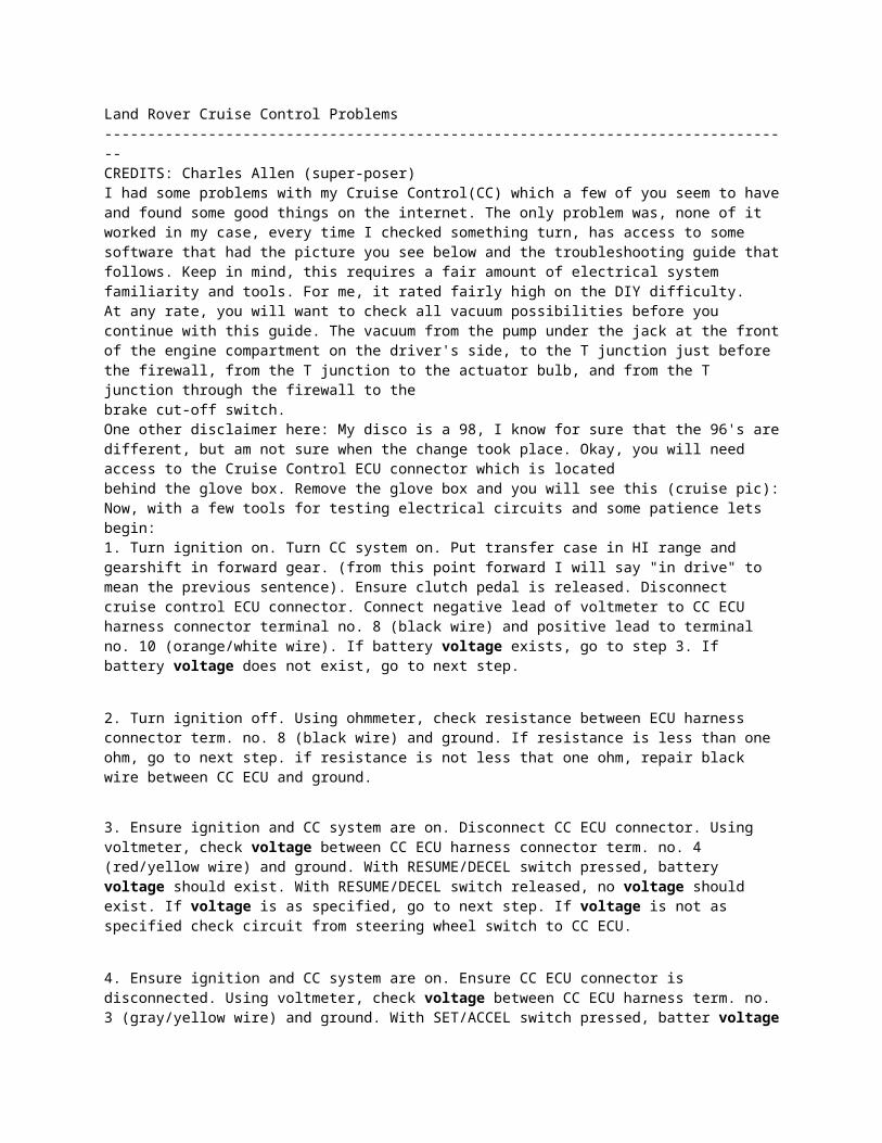
Land Rover Cruise Control Problems --------------------------------------------------------------------------------CREDITS: Charles Allen (super-poser)I had some problems with my Cruise Control(CC) which a few of you seem to have and found some good things on the internet. The only problem was, none of it worked in my case, every time I checked something turn, has access to some software that had the picture you see below and the troubleshooting guide that follows. Keep in mind, this requires a fair amount of electrical system familiarity and tools. For me, it rated fairly high on the DIY difficulty.At any rate, you will want to check all vacuum possibilities before you continue with this guide. The vacuum from the pump under the jack at the front of the engine compartment on the driver's side, to the T junction just before the firewall, from the T junction to the actuator bulb, and from the T junction through the firewall to the
brake cut-off switch.One other disclaimer here: My disco is a 98, I know for sure that the 96's are different, but am not sure when the change took place. Okay, you will need access to the Cruise Control ECU connector which is locatedbehind the glove box. Remove the glove box and you will see this (cruise pic):Now, with a few tools for testing electrical circuits and some patience lets begin:1. Turn ignition on. Turn CC system on. Put transfer case in HI range and gearshift in forward gear. (from this point forward I will say "in drive" to mean the previous sentence). Ensure clutch pedal is released. Disconnect cruise control ECU connector. Connect negative lead of voltmeter to CC ECU harness connector terminal no. 8 (black wire) and positive lead to terminal no. 10 (orange/white wire). If battery voltage exists, go to step 3. If battery voltage does not exist, go to next step.
2. Turn ignition off. Using ohmmeter, check resistance between ECU harness connector term. no. 8 (black wire) and ground. If resistance is less than one ohm, go to next step. if resistance is not less that one ohm, repair black wire between CC ECU and ground.
3. Ensure ignition and CC system are on. Disconnect CC ECU connector. Using voltmeter, check voltage between CC ECU harness connector term. no. 4 (red/yellow wire) and ground. With RESUME/DECEL switch pressed, battery voltage should exist. With RESUME/DECEL switch released, no voltage should exist. If voltage is as specified, go to next step. If voltage is not as specified check circuit from steering wheel switch to CC ECU.
4. Ensure ignition and CC system are on. Ensure CC ECU connector is disconnected. Using voltmeter, check voltage between CC ECU harness term. no. 3 (gray/yellow wire) and ground. With SET/ACCEL switch pressed, batter voltage should exist. With SET/ACCEL switch released, no voltage should exist. If voltage is as specified, go to next step. If voltage is not as specified, check circuit from steering wheel switch toCC ECU.
5. Ensure ignition is on. Ensure CC ECU connector is disconnected. Using voltmeter, check voltage between CC ECU harness term no. 5 (green/purple wire) and ground. With brake pedal pressed, battery voltage should exist. With brake pedal released, no voltage should exist. If voltage is as specified, go to next step. If voltage is not as specified, check green/purple wire between CC ECU and stoplight switch. Check stoplight switch. Repair as necessary.
6. Turn ignition on. Reconnect CC ECU connector. Using voltmeter, back-probe between CC ECU harness term no. 11 (yellow wire) and ground. Spin a rear tire at about 3 MPH. Voltage should be about 2.5 volts, or vary between zero and 5 volts. If voltage is as specified, go to next step. If voltage is not as specified, check yellowwire from CC ECU to the vehicle speed sensor. Check ECU. Repair as necessary.
7. Turn ignition on. Turn CC system on. Disconnect CC ECU harness connector. Connect a fused jumper wire between CC ECU harness term No. 1 (Orange/blue wire) and battery voltage. Connect another fused jumper wire between CC ECU harness term no. 7 (orange/red wire) and ground. If vacuum pump operates, go tonext step. If vacuum pump does not operate, check orange/blue and orange/red wires between CC ECU and vacuum pump. Check Vacuum pump. Repair as necessary.
8. Ensure ignition and CC system are on. Ensure CC ECU connector is disconnected. Connect a fuse jumper wire between CC ECU harness term. no. 1 (orange/blue wire) and battery voltage. Connect another fused jumper wire between CC ECU harness term. no. 7 (orange/red wire) and ground. Connect another fused jumper wire between CC ECU harness term. no. 6 (orange/pink wire) and ground. Vacuum pump should operate, valve should close and throttle should open wide. If system operates as specified, repair CC ECU. If system does not operate as specified, check orange/pink wire between CC ECU and vacuum pump. Check vacuum pump. Repair as necessary.I hope this helps someone. It's a fairly easy way to diagnose any electrical or component problem with this cruise control system. Read: Do steps 7 and 8 to check your vacuum pump.In my case the ECU was bad.
The follow is my experience in replacing the fuel pump using the non-LR part number listed in the Tech section - Parts Cross Reference . This is for a 4.0 – ’97, ’98 & ’99 D1 (different part numbers are listed for ’96 4.0 & the earlier 3.9). This is a really easy low tech job and about as easy to access as anything on your truck. It cost me just under $100 for all the parts and an extra 10 minutes to take apart the assembly to put the new pump in.
*Normal Disclaimer: I take responsibility for what I do on my truck, you do the same. This is a great and easy way to save quite a bit of coin and get a high quality pump w/ a lifetime guarantee; however, it is not a genuine LR part. Take your time and don’t break anything or you may have to buy a new pump assembly!
Notes:- have a fire extinguisher on hand- it’s easiest to do this w/ a ¼ tank or less, but can still be done w/ any amount of fuel in tank
* What you need before you take anything apart:- New fuel pump: MASTER E3270 – ask for pump from ’96 Chevy Impala V8 SS- New pump filter: MASTER FS22- ½” Fuel injection line: ~6” (note - regular fuel line isn’t flexible enough for the spring loaded assembly)*- 2x ½” fuel line clamps: note – fuel line clamps, not regular hose clamps are recommended- Fuel pressure gauge: if you have a Disco you should have this in your toolbox
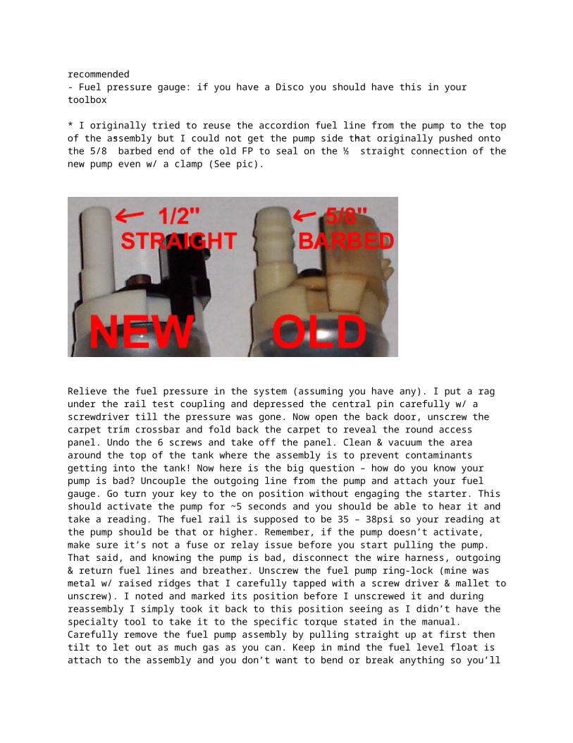
* I originally tried to reuse the accordion fuel line from the pump to the top of the assembly but I could not get the pump side that originally pushed onto the 5/8” barbed end of the old FP to seal on the ½” straight connection of the new pump even w/ a clamp (See pic).
Relieve the fuel pressure in the system (assuming you have any). I put a rag under the rail test coupling and depressed the central pin carefully w/ a screwdriver till the pressure was gone. Now open the back door, unscrew the carpet trim crossbar and fold back the carpet to reveal the round access panel. Undo the 6 screws and take off the panel. Clean & vacuum the area around the top of the tank where the assembly is to prevent contaminants getting into the tank! Now here is the big question – how do you know your pump is bad? Uncouple the outgoing line from the pump and attach your fuel gauge. Go turn your key to the on position without engaging the starter. This should activate the pump for ~5 seconds and you should be able to hear it and take a reading. The fuel rail is supposed to be 35 – 38psi so your reading at the pump should be that or higher. Remember, if the pump doesn’t activate, make sure it’s not a fuse or relay issue before you start pulling the pump. That said, and knowing the pump is bad, disconnect the wire harness, outgoing & return fuel lines and breather. Unscrew the fuel pump ring-lock (mine was metal w/ raised ridges that I carefully tapped with a screw driver & mallet to unscrew). I noted and marked its position before I unscrewed it and during reassembly I simply took it back to this position seeing as I didn’t have the specialty tool to take it to the specific torque stated in the manual. Carefully remove the fuel pump assembly by pulling straight up at first then tilt to let out as much gas as you can. Keep in mind the fuel level float is attach to the assembly and you don’t want to bend or break anything so you’ll have to tilt the assembly as you lift it out of the tank. The assembly is a really tight fit into the tank O-ring seal so it will take some effort.
I carefully popped off the float for ease of handling the assembly; if you do this be very careful not to break the tabs that hold it in place! Separate the electrical connection from
the pump (1), remove two screws (2) holding the fuel line retaining bracket and remove the hose from the pump (3) and the outlet connection above it (4). Push in the four tabs along the lower part of the housing (5) and separate the two halves – the two halves will still be connected via the return line on the assembly.
Take out the pump w/ the pump filter. Pry off the filter (6) and reuse the plastic bracket (7) on the bottom of the pump and the two rubber boots that go on the end of it (you’ll see the rubber boots in the lower half of the assembly when you take out the old pump). Make sure and clean out any particulate you find inside the assemble
Put the old bracket on the new pump then attach the new pump filter. Add the two rubber boots and put the new pump inside the assembly (you’ll have to bend up the pump filter like the old one was). Then snap the two halves of the assembly back together. Remove the old accordion fuel line from the retaining bracket and slide the fuel injection line through the rubber grommet in the retaining bracket. This is a real tight fit so you can use a small amount of new motor oil to lubricate. Attach the fuel line to the new pump (3) and secure it w/ a clamp. (2) Reattach the fuel line retaining bracket then attach fuel line to assembly (4) and secure w/ clamp. Insert electrical connection (1) – this is an exact fit & polarized correctly. Reattach the float if you removed it and you’re ready to install by reversing the process of removal. I reused the tank seal O-ring as it was still in very good shape. I suggest you install it around the tank opening first then put the assembly in rather than it other way around. Now hook everything back up except the outgoing line and use it to test pressure. This pump is rated at 60psi I believe. When you’re done with this, reconnect the outgoing line, start your engine and take a test drive then check for leaks and the pressure at the rail before you replace the access panel, carpet and trim crossbar. If you haven’t already, you should put in a new inline fuel filter that can accessed via the right rear wheel well as a matter of maintenance. If you still have low pressure at the rail with the new pump and inline fuel filter you should suspect the fuel regulator and/ or leaky injectors. I had low pressure & drop off to zero when the key turned off because I couldn’t get the old accordion fuel line on the assembly to seal around the outlet on the new pump, so I had to take out the assembly and replace the old line with new fuel injector line.
Disco Wheel bearings and seals (RR seals are better)
- 8 of Timken SET37, SKF BR37, FAG KIT38 or National A-37 (available at any parts store)
- 4 of hub seal RTC3511 (available from any Rover parts supplier like http://www.rovahfarm.com/)
engine description part number comment price/where
4.0 serpentine belt goodyear gatorback p/n 4070884
by bill b.
96 4.0 fuel filter purolator F33144
4.0 fuel pump MATER E3270 Mike Meyerauto zone for 79.99 lifetime warranty
3.9 fuel pump Carter P74006
3.9 fuel pump AC-Delco EP-241 GMC
3.9 fuel pump NAPA BK-610-1011 NAPA
3.9 fuel pump P74006 NAPA
3.9 idle air control valve IAC valve stepper motor
NAPA Part # MPF21738 by mike cox
4.0 idle Air Control Valve stepper motor AC-151 by pk
3.9 idle air control valve IAC valve stepper motor
AC Delco Part Number #25527077
by mike cox
- front disco1 brakepads BENDIX Part #141754 not proven -
- Tcase bearings Timken 6207 proven -
- Wheel bearings Timken 37 proven -
- Air filter disco1 Beck Arnley, made by Crosland, #042-1579
by Tate -
- Air Filter disco1 Wix: #42285 by Tate -
- Oil Filter disco1 Wix #51068 by Tate -
- Fuel Filter Wix #33481 by Tate -
- Spark Plug NGK V-Power BPR5EY, Stock #1233
by Tate -
- Precision U-joints, (discos may vary) NAPA #344 front and rear


![Cold Start Up[1].](https://static.documents.pub/doc/80x56/577d352d1a28ab3a6b8fbb5e/cold-start-up1.jpg)

