T-45C – Cold Start Procedure Based on the NATOP’s Flight Manual A1-T45AC-NFM-000 Summarized by Eduardo “Rudel_chw” Ahumada. In blue those items that can be omitted when on a hurry. In Red, items not implemented yet. 7.4 INTERIOR CHECK: 3. Parking brake – SET (From “7.3.2 In the Cockpit”). Engage by pulling the PARKING BRAKE handle until fully extended and rotating it clockwise. On DCS it requires just a click. The PK BRK caution light will illuminate if the throttle is advanced beyond the intermediate position while the Parking Brake is set. (Not implemented) 7. ENGINE switch – ON. The ENGINE switch is located on the left console. The switch has the following positions: START: This momentary position accelerates the GTS to full power, then automatically opens the start valve to admit air to the ATS, starting the engine. Use right click & hold to actuate. ON: Energizes the start control unit and permits fuel boost pump number 2 operation if all other parameters are met. Use left click to switch between OFF & ON. OFF: Manually shuts down the GTS operation and de-energizes the start control unit and, after 30 seconds, shuts the fuel boost pump number 2 OFF.
Transcript
T-45C – Cold Start Procedure Based on the NATOP’s Flight Manual A1-T45AC-NFM-000 Summarized by Eduardo “Rudel_chw” Ahumada. In blue those items that can be omitted when on a hurry. In Red, items not implemented yet.
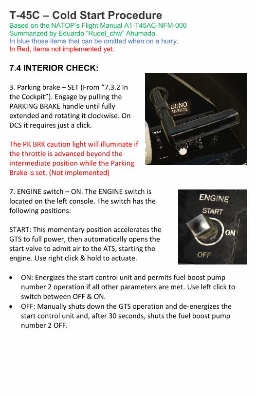
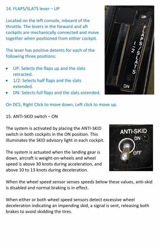
7.4 INTERIOR CHECK: 3. Parking brake – SET (From “7.3.2 In the Cockpit”). Engage by pulling the PARKING BRAKE handle until fully extended and rotating it clockwise. On DCS it requires just a click. The PK BRK caution light will illuminate if the throttle is advanced beyond the intermediate position while the Parking Brake is set. (Not implemented) 7. ENGINE switch – ON. The ENGINE switch is located on the left console. The switch has the following positions: START: This momentary position accelerates the GTS to full power, then automatically opens the start valve to admit air to the ATS, starting the engine. Use right click & hold to actuate.
ON: Energizes the start control unit and permits fuel boost pump number 2 operation if all other parameters are met. Use left click to switch between OFF & ON.
OFF: Manually shuts down the GTS operation and de-energizes the start control unit and, after 30 seconds, shuts the fuel boost pump number 2 OFF.
8. RUDDER TRIM knob – NEUTRAL. Located aft of the throttle, and is spring loaded to the center, neutral position. Rotating the knob left or right adds the corresponding rudder trim.
The rudder trim indicator is located forward of the throttle and indicates rudder trim position.
12. Throttle – Check it’s at OFF. The throttle controls the engine thrust in response to the throttle movement. The real Throttle has 4 detents:
Full Forward: Operates engine at Maximum Rated Thrust (MRT)
APPROACH IDLE: With landing gear down and aircraft weight-off-wheels, maintains minimum RPM at approximately 72%.
IDLE: Opens fuel shutoff valve to direct fuel to fuel spray nozzles.
OFF: Interrupts or prevents fuel flow to engine. On DCS press [Home] to actuate the Finger-lift, or click on it, to move the Throttle from OFF to IDLE and vice versa. 13. EXTERIOR LIGHTS master switch – AS REQUIRED. On DCS, use [L] for OFF and [LCtrl + L] for ON.
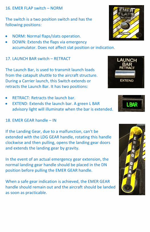
14. FLAPS/SLATS lever – UP Located on the left console, inboard of the throttle. The levers in the forward and aft cockpits are mechanically connected and move together when positioned from either cockpit. The lever has positive detents for each of the following three positions:
UP: Selects the flaps up and the slats retracted.
1/2: Selects half flaps and the slats extended.
DN: Selects full flaps and the slats extended. On DCS, Right Click to move down, Left click to move up. 15. ANTI-SKID switch – ON The system is activated by placing the ANTI-SKID switch in both cockpits in the ON position. This illuminates the SKID advisory light in each cockpit. The system is actuated when the landing gear is down, aircraft is weight-on-wheels and wheel speed is above 30 knots during acceleration, and above 10 to 13 knots during deceleration. When the wheel speed sensor senses speeds below these values, anti-skid is disabled and normal braking is in effect. When either or both wheel speed sensors detect excessive wheel deceleration indicating an impending skid, a signal is sent, releasing both brakes to avoid skidding the tires.
16. EMER FLAP switch – NORM The switch is a two position switch and has the following positions:
NORM: Normal flaps/slats operation.
DOWN: Extends the flaps via emergency accumulator. Does not affect slat position or indication.
17. LAUNCH BAR switch – RETRACT The Launch Bar, is used to transmit launch loads from the catapult shuttle to the aircraft structure. During a Carrier launch, this Switch extends or retracts the Launch Bar. It has two positions:
RETRACT: Retracts the launch bar.
EXTEND: Extends the launch bar. A green L BAR advisory light will illuminate when the bar is extended.
18. EMER GEAR handle – IN If the Landing Gear, due to a malfunction, can’t be extended with the LDG GEAR handle, rotating this handle clockwise and then pulling, opens the landing gear doors and extends the landing gear by gravity. In the event of an actual emergency gear extension, the normal landing gear handle should be placed in the DN position before pulling the EMER GEAR handle. When a safe gear indication is achieved, the EMER GEAR handle should remain out and the aircraft should be landed as soon as practicable.
19. LDG GEAR handle – DOWN The LDG GEAR handle is located on the left vertical console.
UP: With the aircraft weight off all wheels, raises the landing gear.
DN: Lowers the landing gear. The landing gear position lights are green in and labeled: NOSE, LEFT, and RIGHT. The light illuminates when the corresponding gear is down and locked. 20. MASTER ARM switch – SAFE All armament circuits are controlled by the master armament switch, with the exception of emergency jettisoning of external stores.
SAFE: De-energizes armament circuits.
MASTER ARM: Energizes armament circuits and illuminates MSTR ARM indicator light in the aft cockpit.
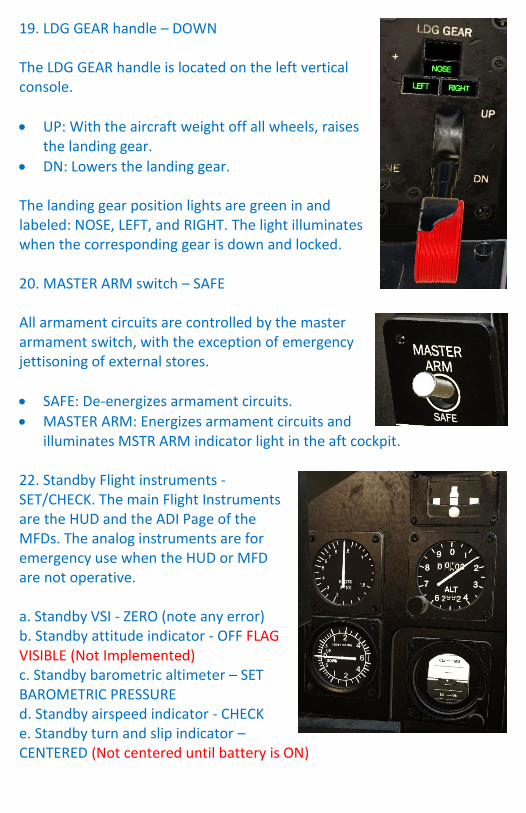
22. Standby Flight instruments - SET/CHECK. The main Flight Instruments are the HUD and the ADI Page of the MFDs. The analog instruments are for emergency use when the HUD or MFD are not operative. a. Standby VSI - ZERO (note any error) b. Standby attitude indicator - OFF FLAG VISIBLE (Not Implemented) c. Standby barometric altimeter – SET BAROMETRIC PRESSURE d. Standby airspeed indicator - CHECK e. Standby turn and slip indicator – CENTERED (Not centered until battery is ON)
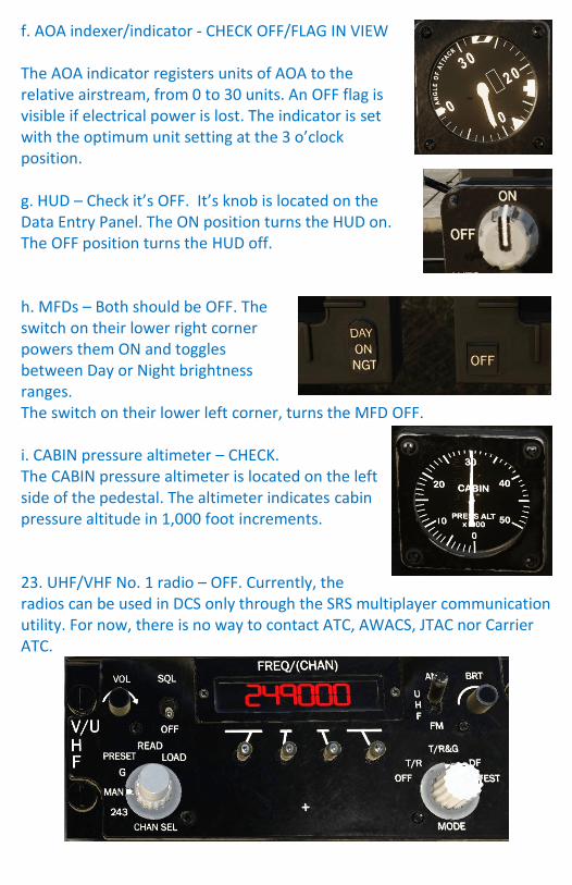
f. AOA indexer/indicator - CHECK OFF/FLAG IN VIEW The AOA indicator registers units of AOA to the relative airstream, from 0 to 30 units. An OFF flag is visible if electrical power is lost. The indicator is set with the optimum unit setting at the 3 o’clock position. g. HUD – Check it’s OFF. It’s knob is located on the Data Entry Panel. The ON position turns the HUD on. The OFF position turns the HUD off. h. MFDs – Both should be OFF. The switch on their lower right corner powers them ON and toggles between Day or Night brightness ranges. The switch on their lower left corner, turns the MFD OFF. i. CABIN pressure altimeter – CHECK. The CABIN pressure altimeter is located on the left side of the pedestal. The altimeter indicates cabin pressure altitude in 1,000 foot increments. 23. UHF/VHF No. 1 radio – OFF. Currently, the radios can be used in DCS only through the SRS multiplayer communication utility. For now, there is no way to contact ATC, AWACS, JTAC nor Carrier ATC.
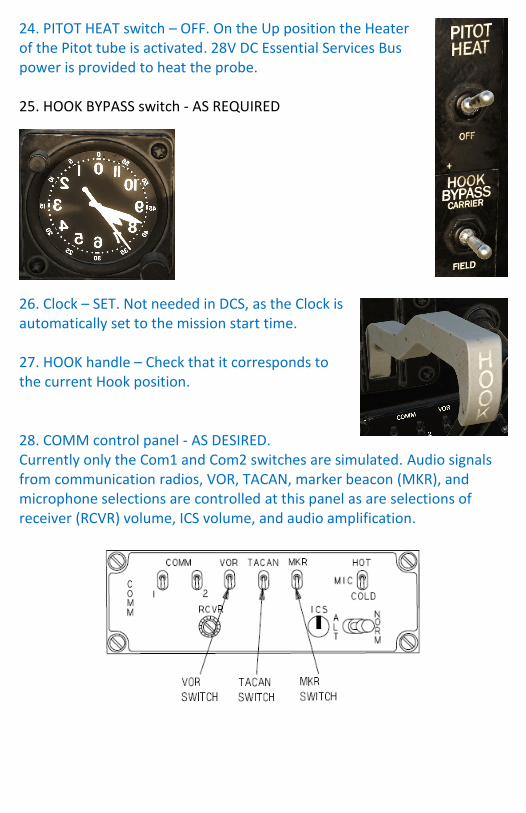
24. PITOT HEAT switch – OFF. On the Up position the Heater of the Pitot tube is activated. 28V DC Essential Services Bus power is provided to heat the probe. 25. HOOK BYPASS switch - AS REQUIRED
26. Clock – SET. Not needed in DCS, as the Clock is automatically set to the mission start time. 27. HOOK handle – Check that it corresponds to the current Hook position. 28. COMM control panel - AS DESIRED. Currently only the Com1 and Com2 switches are simulated. Audio signals from communication radios, VOR, TACAN, marker beacon (MKR), and microphone selections are controlled at this panel as are selections of receiver (RCVR) volume, ICS volume, and audio amplification.
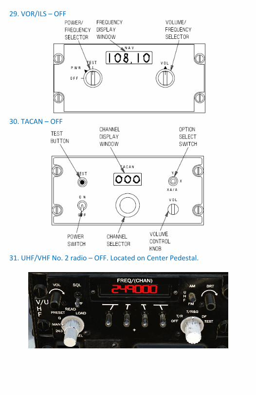
29. VOR/ILS – OFF
30. TACAN – OFF
31. UHF/VHF No. 2 radio – OFF. Located on Center Pedestal.
32. IFF – OFF. Not Simulated.
33. BATT switches - OFF 34. AC RESET switch – CENTERED 35. GEN switch – ON. The GEN switch is located on the PWR panel, on the right console and is a three position toggle switch, spring loaded to the ON position. The switch has the following positions:
RESET: Resets the generator voltage regulator.
ON: Generator is on, excitation power is supplied from the 28 VDC Essential Services Bus.
OFF Excitation power is removed, turning off the generator.
41. A-COLL/STROBE light switch – Set to A-COLL. This switch has three positions:
A-COLL/ STROBE: Turns on both red anti-collision lights and the white strobe light.
A-COLL: Turns on the red anti-collision lights only.
OFF: Turns off the anti-collision and strobe lights. 38. Exterior lights - AS DESIRED:
NAVIGATION Lights Switch. FLASH Wing and/or tail navigation lights flash if selected. STEADY the lights operate steady if selected.
TAIL Lights Switch. Can be set Bright, Off or Dim.
WING Lights Switch. Can be set Bright, Off or Dim.
FORMATION Lights Switch. Can be set Bright, Off or Dim.
39. Cockpit air conditioning - NORMAL/AS DESIRED. (Not Simulated) 40. Interior lights - AS REQUIRED. (MIP: Main Instrument Panel)
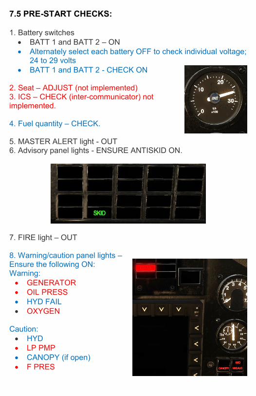
7.5 PRE-START CHECKS: 1. Battery switches
BATT 1 and BATT 2 – ON
Alternately select each battery OFF to check individual voltage; 24 to 29 volts
BATT 1 and BATT 2 - CHECK ON 2. Seat – ADJUST (not implemented) 3. ICS – CHECK (inter-communicator) not implemented. 4. Fuel quantity – CHECK. 5. MASTER ALERT light - OUT 6. Advisory panel lights - ENSURE ANTISKID ON.
7. FIRE light – OUT 8. Warning/caution panel lights – Ensure the following ON: Warning:
GENERATOR
OIL PRESS
HYD FAIL
OXYGEN
Caution:
HYD
LP PMP
CANOPY (if open)
F PRES
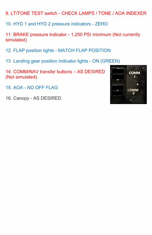
9. LT/TONE TEST switch - CHECK LAMPS / TONE / AOA INDEXER 10. HYD 1 and HYD 2 pressure indicators - ZERO 11. BRAKE pressure indicator - 1,250 PSI minimum (Not currently simulated) 12. FLAP position lights - MATCH FLAP POSITION 13. Landing gear position indicator lights - ON (GREEN) 14. COMM/NAV transfer buttons – AS DESIRED (Not simulated). 15. AOA - NO OFF FLAG 16. Canopy - AS DESIRED
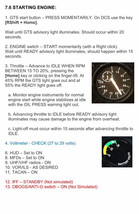
7.6 STARTING ENGINE: 1. GTS start button – PRESS MOMENTARILY. On DCS use the key [RShift + Home]. Wait until GTS advisory light illuminates. Should occur within 20 seconds.
2. ENGINE switch – START momentarily (with a Right click). Wait until READY advisory light illuminates, should happen within 15 seconds.
3. Throttle – Advance to IDLE WHEN RPM BETWEEN 15 TO 20%, pressing the [Home] key or clicking on the finger-lift. At 45% RPM the GTS light goes out and at 55% the READY light goes off.
a. Monitor engine instruments for normal engine start while engine stabilizes at idle with the OIL PRESS warning light out. b. Advancing throttle to IDLE before READY advisory light illuminates may cause damage to the engine from overheat. c. Light-off must occur within 15 seconds after advancing throttle to IDLE.
4. Voltmeter - CHECK (27 to 29 volts) 6. HUD – Set to ON 8. MFDs – Set to ON 9. UHF/VHF radios - ON 10. VOR/ILS - AS DESIRED 11. TACAN – ON 12. IFF – STANDBY (Not simulated) 13. OBOGS/ANTI-G switch – ON (Not Simulated)
7.7 POST-START: 1. Throttle - ADVANCE SLOWLY TO 70% RPM Following start, do not advance the throttle rapidly before the bleed valve closes, as there is a possibility that the engine will overheat. Once the bleed valve is closed there are no restrictions on the rate of throttle movement. 2. FUEL CONTR switch - MANUAL MFUEL advisory light illuminates. Note engine RPM may decrease by up to 6 percent. 3. FUEL CONTR switch – NORMAL M FUEL advisory light goes out and ensure previous RPM is achieved. 4. HYD 2 RESET button - PRESS Check that HYD caution light goes out and hydraulic pressure indicates in normal range 5. Hydraulic pressures - Check 3,000 PSI
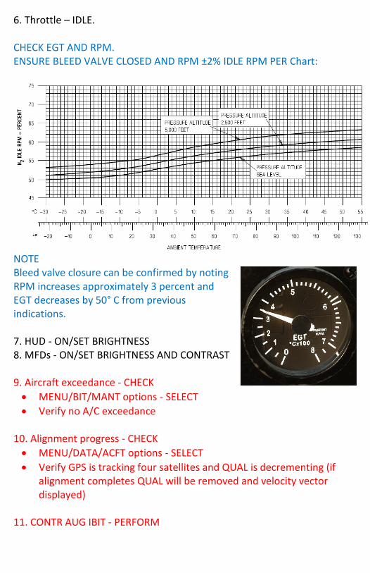
6. Throttle – IDLE. CHECK EGT AND RPM. ENSURE BLEED VALVE CLOSED AND RPM ±2% IDLE RPM PER Chart:
NOTE Bleed valve closure can be confirmed by noting RPM increases approximately 3 percent and EGT decreases by 50° C from previous indications. 7. HUD - ON/SET BRIGHTNESS 8. MFDs - ON/SET BRIGHTNESS AND CONTRAST 9. Aircraft exceedance - CHECK
MENU/BIT/MANT options - SELECT
Verify no A/C exceedance 10. Alignment progress - CHECK
MENU/DATA/ACFT options - SELECT
Verify GPS is tracking four satellites and QUAL is decrementing (if alignment completes QUAL will be removed and velocity vector displayed)
11. CONTR AUG IBIT - PERFORM
12. Stabilator trim: a. Pitch trim - CHECK BOTH DIRECTIONS (-3° to +8°) b. STBY STAB TRIM switch – LIFT GUARD COVER AND CHECK NORMAL TRIM STOPS. CHECK BOTH DIRECTIONS, CLOSE GUARD c. Pitch trim - SET FOR TAKEOFF/CATAPULT
Shore Take-Off: 2-3° Nose Up.
Carrier: 3.5° Nose Up 13. Aileron trim - CHECK BOTH DIRECTIONS AND SET AT NEUTRAL 14. Rudder trim - CHECK BOTH DIRECTIONS AND SET AT NEUTRAL. 15. Standby attitude indicator - PUSH TO ERECT.
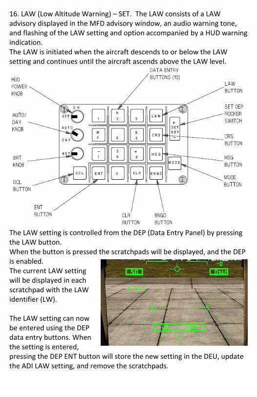
16. LAW (Low Altitude Warning) – SET. The LAW consists of a LAW advisory displayed in the MFD advisory window, an audio warning tone, and flashing of the LAW setting and option accompanied by a HUD warning indication. The LAW is initiated when the aircraft descends to or below the LAW setting and continues until the aircraft ascends above the LAW level.
The LAW setting is controlled from the DEP (Data Entry Panel) by pressing the LAW button. When the button is pressed the scratchpads will be displayed, and the DEP is enabled. The current LAW setting will be displayed in each scratchpad with the LAW identifier (LW). The LAW setting can now be entered using the DEP data entry buttons. When the setting is entered, pressing the DEP ENT button will store the new setting in the DEU, update the ADI LAW setting, and remove the scratchpads.
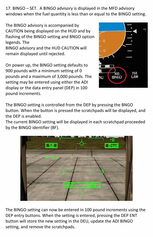
17. BINGO – SET. A BINGO advisory is displayed in the MFD advisory windows when the fuel quantity is less than or equal to the BINGO setting. The BINGO advisory is accompanied by CAUTION being displayed on the HUD and by flashing of the BINGO setting and BNGO option legends. The BINGO advisory and the HUD CAUTION will remain displayed until rejected. On power up, the BINGO setting defaults to 900 pounds with a minimum setting of 0 pounds and a maximum of 3,000 pounds. The setting may be entered using either the ADI display or the data entry panel (DEP) in 100 pound increments. The BINGO setting is controlled from the DEP by pressing the BNGO button. When the button is pressed the scratchpads will be displayed, and the DEP is enabled. The current BINGO setting will be displayed in each scratchpad proceeded by the BINGO identifier (BF).
The BINGO setting can now be entered in 100 pound increments using the DEP entry buttons. When the setting is entered, pressing the DEP ENT button will store the new setting in the DEU, update the ADI BINGO setting, and remove the scratchpads.
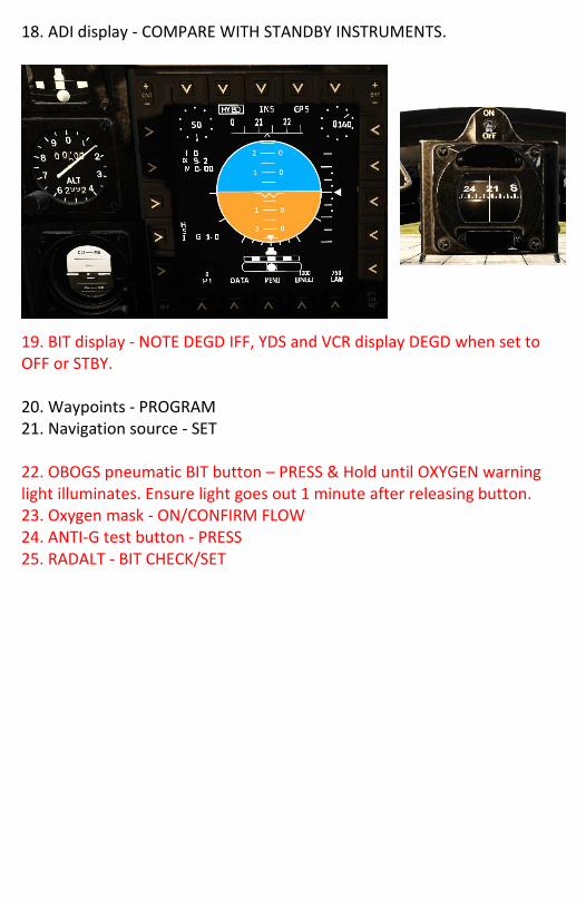
18. ADI display - COMPARE WITH STANDBY INSTRUMENTS.
19. BIT display - NOTE DEGD IFF, YDS and VCR display DEGD when set to OFF or STBY. 20. Waypoints - PROGRAM 21. Navigation source - SET 22. OBOGS pneumatic BIT button – PRESS & Hold until OXYGEN warning light illuminates. Ensure light goes out 1 minute after releasing button. 23. Oxygen mask - ON/CONFIRM FLOW 24. ANTI-G test button - PRESS 25. RADALT - BIT CHECK/SET
7.7.1 CHECK WITH PLANE CAPTAIN 1. Flight controls - FREE, FULL TRAVEL AND PROPER
MOVEMENT 2. Nose Wheel Steering – ENGAGE. On DCS, the NWS is always
engaged. The Flight Stick NWS button is used to select a higher turn rate and must be held.
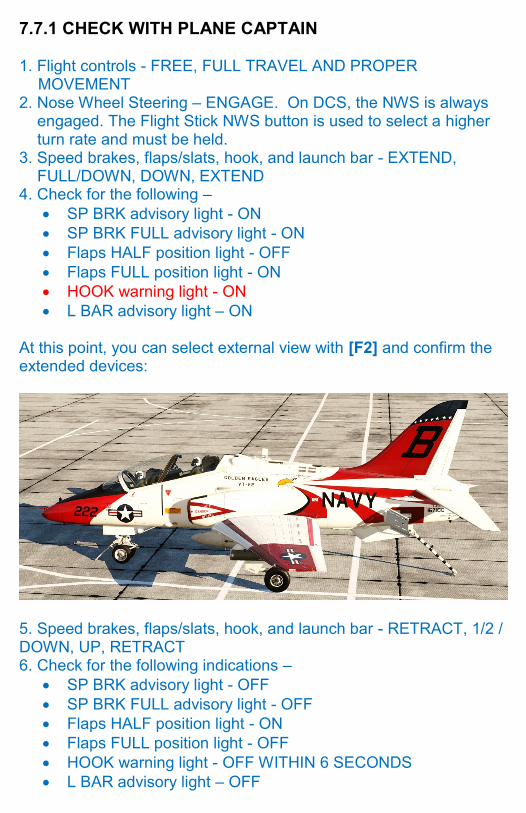
3. Speed brakes, flaps/slats, hook, and launch bar - EXTEND, FULL/DOWN, DOWN, EXTEND
4. Check for the following –
SP BRK advisory light - ON
SP BRK FULL advisory light - ON
Flaps HALF position light - OFF
Flaps FULL position light - ON
HOOK warning light - ON
L BAR advisory light – ON At this point, you can select external view with [F2] and confirm the extended devices:
5. Speed brakes, flaps/slats, hook, and launch bar - RETRACT, 1/2 / DOWN, UP, RETRACT 6. Check for the following indications –