66
14.1.a Packet Pg. 216 Attachment: Engineering Standards Manual Draft (2016 : Approval of the Engineering Standards Manual)
14.1.a
Packet Pg. 216
Atta
chm
ent:
Engi
neer
ing
Stan
dard
s M
anua
l Dra
ft (2
016
: App
rova
l of t
he E
ngin
eerin
g St
anda
rds
Man
ual)
City of Fort Walton Beach Engineering Standards Manual November 2012
~ 1 ~
City of Fort Walton Beach
EEngineering Standards Manual
TABLE OF CONTENTS SECTION 1.00 – INTRODUCTION ............................................................................................. 3 SECTION 2.00 – POLICY ........................................................................................................... 3 SECTION 3.00 - EROSION AND SEDIMENTATION CONTROL ...................................................... 3 EROSION AND SEDIMENTATION CONTROL STANDARD DETAILS ESM- 3.01 Silt Fence ............................................................................................................ 4 ESM -3.02 Floating Turbidity Barrier ................................................................................... 5 ESM -3.03 Inlet Protection .................................................................................................. 6 SECTION 4.00 – STORMWATER ............................................................................................... 7 4.01 – Design Standards ............................................................................................. 7 4.02 – Stormwater As-builts ....................................................................................... 8 STORMWATER STANDARD DETAILS ESM - 4.01 Retention Pond ................................................................................................. 9 ESM - 4.02 Detention Pond ............................................................................................... 10 ESM - 4.03 Type “C” Catch Basin ...................................................................................... 11 ESM - 4.04 Type “D” Catch Basin ...................................................................................... 12 ESM - 4.05 Type “E” Catch Basin ....................................................................................... 13 ESM - 4.06 Oil Skimmer for Outfall Structure ................................................................... 14 ESM - 4.07 Mitered End Section and Concrete Collar ...................................................... 15 ESM - 4.08 Standard Saddle Curb Inlet ............................................................................. 16 ESM - 4.09 Standard French Drain .................................................................................... 17 ESM - 4.10 Standard Underdrain Exfiltration ................................................................... 18 SECTION 5.00 – STREETS ....................................................................................................... 19 5.01 – Street Layout ................................................................................................. 19 5.02 – Pavement Design ........................................................................................... 19 5.03 – Curb & Gutter ................................................................................................ 20 STREETS STANDARD DETAILS ESM - 5.01 2-Lane City Street (60’ ROW) .......................................................................... 21 ESM - 5.02 4-Lane Undivided City Street (96’ ROW) ........................................................ 22 ESM - 5.03 4-Lane Divided City Street (112’ ROW) ........................................................... 23 ESM - 5.04 Standard Cul-de-sac ........................................................................................ 24 ESM - 5.05 Standard Offset Cul-de-sac ............................................................................. 25 ESM - 5.06 Standard T – Turn Around .............................................................................. 26 ESM - 5.07 Standard 2’ Ribbon Curb ................................................................................. 27 ESM - 5.08 Standard Drop Curb ........................................................................................ 28 ESM - 5.09 Standard Squareback Curb ............................................................................. 29 ESM - 5.10 Standard Rollback Curb & Gutter ................................................................... 30
SECTION 6.00 PARKING & VEHICULAR ACCESSABILITY ........................................................... 31
14.1.a
Packet Pg. 217
Atta
chm
ent:
Engi
neer
ing
Stan
dard
s M
anua
l Dra
ft (2
016
: App
rova
l of t
he E
ngin
eerin
g St
anda
rds
Man
ual)

City of Fort Walton Beach Engineering Standards Manual November 2012
~ 2 ~
6.01 – Off Street Vehicle Parking .............................................................................. 31 6.02 – Off Street Vehicle Loading .............................................................................. 31 6.03 – Bicycle Parking ............................................................................................... 31 6.04 – Parking Lot Design Standards ......................................................................... 31 PARKING AND VEHICULAR ACCESSABILITY STANDARD DETAILS ESM - 6.01 Bicycle Parking ................................................................................................ 32
SECTION 7.00 SIDEWALKS, MULTI-USE PATHS & DRIVEWAYS ................................................ 33 7.01 – Sidewalk Design Standards ............................................................................. 33 7.02 – Multi-use Path Design Standards .................................................................... 33 7.03 – Driveway Design Standards ............................................................................ 34 SIDEWALKS, MULTI-USE PATHS & DRIVEWAY STANDARD DETAILS ESM - 7.01 Standard Sidewalk .......................................................................................... 35 ESM - 7.02 Multi-use Path ................................................................................................ 36 ESM - 7.03 Standard Residential Driveway ....................................................................... 37 ESM - 7.04 Standard Commercial Driveway ..................................................................... 38 ESM - 7.05 Standard Commercial Driveway with Sidewalk at Back of Curb .................... 39 ESM - 7.06 Standard Driveway Turnout Curb & Gutter .................................................... 40 SECTION 8.00 ROADSIDE APPENDITURES .............................................................................. 41 8.01 – Solid Waste Receptacle Pads .......................................................................... 41 ROADSIDE APPENDITURE STANDARD DETAILS ESM - 8.01 Standard Concrete Dumpster Pad .................................................................. 42
SECTION 9.00 UTILITIES ........................................................................................................ 43 9.01 – Utility Easements ........................................................................................... 43 9.02 – Potable Water ............................................................................................... 43 9.03 – Sanitary Sewer ............................................................................................... 44 9.04 – Drainage ........................................................................................................ 45 9.05 – Reclaimed Water ........................................................................................... 45 9.06 – Utility As-builts .............................................................................................. 45 UTILITY STANDARD DETAILS ESM - 9.01 Numbers to Call for Line Spots and Other Utility Information ....................... 46 ESM - 9.02 Standard Utility Section .................................................................................. 47 ESM - 9.03 Standard Utility Locations ............................................................................... 48 ESM - 9.04 Water & Sewer Main Crossing/Separation ..................................................... 49 ESM - 9.05 Typical Reclaimed Water/Potable Water Crossing ......................................... 50 ESM - 9.06 Concrete Arch & Encasement ......................................................................... 51 ESM - 9.07 Standard Utility Patch Restoration ................................................................. 52 ESM - 9.08 Trench – Type “A” Bedding ............................................................................. 53 ESM - 9.09 Trench – Type “B” Bedding ............................................................................. 54 ESM - 9.10 Standard Thrust Block ..................................................................................... 55 ESM - 9.11 Gate Valve – 12” & Smaller ............................................................................. 56 ESM - 9.12 Standard Fire Hydrant ..................................................................................... 57 ESM - 9.13 ¾” – 2” Water Meter Installation ................................................................... 58 ESM - 9.14 4” & Larger Water Meter Installation ............................................................. 59 ESM - 9.15 Sanitary Sewer Service Lateral ........................................................................ 60
14.1.a
Packet Pg. 218
Atta
chm
ent:
Engi
neer
ing
Stan
dard
s M
anua
l Dra
ft (2
016
: App
rova
l of t
he E
ngin
eerin
g St
anda
rds
Man
ual)

City of Fort Walton Beach Engineering Standards Manual November 2012
~ 3 ~
ESM - 9.16 Standard Sewer Cleanout ............................................................................... 61 ESM - 9.17 Standard Sewer Manhole ............................................................................... 62 ESM - 9.18 Standard Sewer Manhole with Drop Connection ........................................... 63 APPENDIX 9A APPROVED MATERIALS FOR UTILITY CONSTRUCTION 9A-1 Approved Materials for Potable Water Construction .............................................. 65 9A-2 Approved Materials for Sanitary Sewer Construction.............................................. 67 9A-3 Approved Materials for Drainage Construction ....................................................... 68
14.1.a
Packet Pg. 219
Atta
chm
ent:
Engi
neer
ing
Stan
dard
s M
anua
l Dra
ft (2
016
: App
rova
l of t
he E
ngin
eerin
g St
anda
rds
Man
ual)

City of Fort Walton Beach Engineering Standards Manual November 2012
1.00 INTRODUCTION
The 2012 City of Fort Walton Beach Land Development Code was adopted on March 23, 2012and became effective on May 1, 2012. Many requirements contained in the previous LandDevelopment Code will now be located in the Engineering Standards Manual (ESM) of FortWalton Beach. The ESM is referenced throughout the Land Development Code, containinguniform minimum standards for the design and construction of required improvementsacceptable within the City of Fort Walton Beach.
2.00 POLICY
The Engineering Standards Manual shall serve as the official document that contains theminimum standards for design and construction of required improvements throughout theCity of Fort Walton Beach. The Engineering and Utility Services Director shall establish andmaintain the Engineering Standards Manual and such other standards for work within thepublic rights of way.
3.00 EROSION AND SEDIMENTATION CONTROL
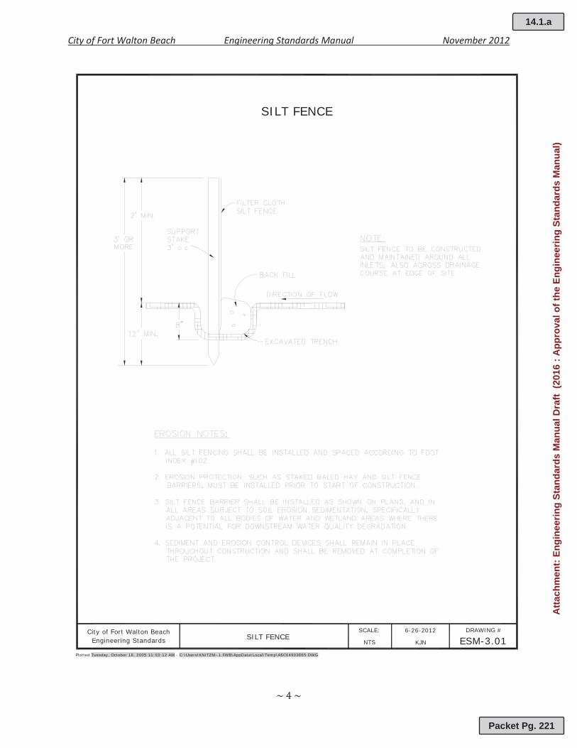
Erosion and sedimentation control measures shall be installed around the perimeter of allconstruction sites that disturb the existing topography. Unless otherwise noted in Citystandard details, all erosion control measures shall comply with the latest version of theFlorida Department of Transportation’s (FDOT) Design Standards and the Florida Departmentof Environmental Protection’s (FDEP) Florida Stormwater Erosion Control and SedimentationControl Inspector’s Manual. All development shall provide for erosion and sedimentationcontrol as follows:
a. An erosion control plan is required as part of the Stormwater Management Plan.b. Before the commencement of construction activity, erosion control measures must be
installed.c. Silt fencing shall be installed around the perimeter of the site to provide for erosion
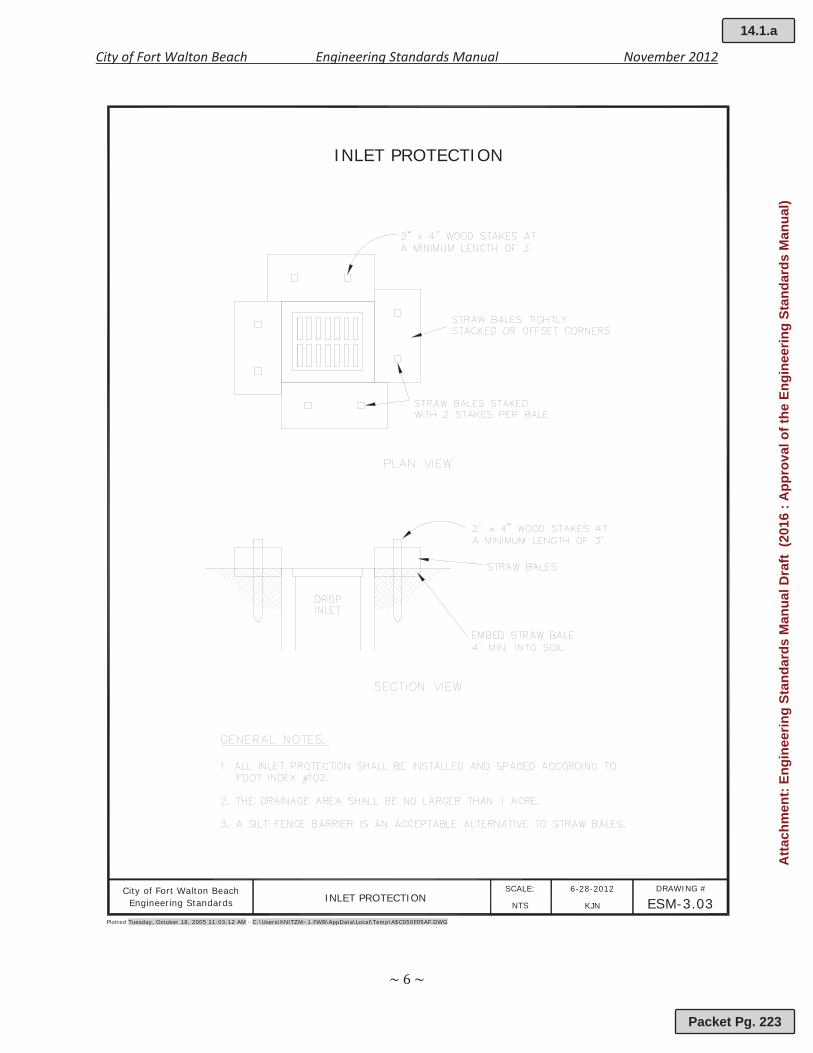
control and define the limits of construction activity.d. Onsite and downstream inlets shall be protected by temporary inlet protection.e. All soil stockpiles shall be protected against dusting and erosion.f. At all times during and after construction, disturbed areas shall be stabilized. Final
stabilized areas shall be sodded/seeded and established prior to project closeout.g. The requirements of an erosion and sedimentation control may be waived by the City for
developments less than one half (1/2) acre in size and are not located upstream fromadjacent properties.
(This section left intentionally blank)
14.1.a
Packet Pg. 220
Atta
chm
ent:
Engi
neer
ing
Stan
dard
s M
anua
l Dra
ft (2
016
: App
rova
l of t
he E
ngin
eerin
g St
anda
rds
Man
ual)
City of Fort Walton Beach Engineering Standards Manual November 2012
City of Fort Walton Beach SILT FENCE
6-26-2012 DRAWING #
ESM-3.01SCALE:
KJN
SILT FENCE
Plotted Tuesday, October 18, 2005 11:03:12 AM - C:\Users\KNITZM~1.FWB\AppData\Local\Temp\A$C64903E65.DWG
NTSEngineering Standards
14.1.a
Packet Pg. 221
Atta
chm
ent:
Engi
neer
ing
Stan
dard
s M
anua
l Dra
ft (2
016
: App
rova
l of t
he E
ngin
eerin
g St
anda
rds
Man
ual)

City of Fort Walton Beach Engineering Standards Manual November 2012
FLOATING TURBIDITY BARRIER
Plotted Tuesday, October 18, 2005 11:03:12 AM - C:\Users\KNITZM~1.FWB\AppData\Local\Temp\A$C096E03C7.DWG
City of Fort Walton BeachFLOATING TURBIDITY BARRIER
6-28-2012 DRAWING #
ESM-3.02SCALE:
KJNNTSEngineering Standards
14.1.a
Packet Pg. 222
Atta
chm
ent:
Engi
neer
ing
Stan
dard
s M
anua
l Dra
ft (2
016
: App
rova
l of t
he E
ngin
eerin
g St
anda
rds
Man
ual)
City of Fort Walton Beach Engineering Standards Manual November 2012
INLET PROTECTION
Plotted Tuesday, October 18, 2005 11:03:12 AM - C:\Users\KNITZM~1.FWB\AppData\Local\Temp\A$C050F05AF.DWG
City of Fort Walton BeachINLET PROTECTION
6-28-2012 DRAWING #
ESM-3.03SCALE:
KJNNTSEngineering Standards
14.1.a
Packet Pg. 223
Atta
chm
ent:
Engi
neer
ing
Stan
dard
s M
anua
l Dra
ft (2
016
: App
rova
l of t
he E
ngin
eerin
g St
anda
rds
Man
ual)
City of Fort Walton Beach Engineering Standards Manual November 2012
4.00 STORMWATER
4.01 Design Standards
In order to ensure the objectives and performance standards of this article will be met, thedesign, construction and maintenance of drainage systems shall be consistent with thefollowing standards:
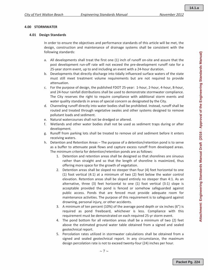
a. All developments shall treat the first one (1) inch of runoff on site and assure that thepost development run off rate will not exceed the pre development runoff rate for a25 year storm event, up to and including an event with a 24 hour duration.
b. Developments that directly discharge into tidally influenced surface waters of the statemust still meet treatment volume requirements but are not required to provideattenuation.
c. For the purpose of design, the published FDOT 25 year: 1 hour, 2 hour, 4 hour, 8 hour,and 24 hour rainfall distributions shall be used to demonstrate stormwater compliance.The City reserves the right to require compliance with additional storm events andwater quality standards in areas of special concern as designated by the City.
d. Channeling runoff directly into water bodies shall be prohibited. Instead, runoff shall berouted and treated through vegetative swales and other systems designed to removepollutant loads and sediment.
e. Natural watercourses shall not be dredged or altered.f. Wetlands and other water bodies shall not be used as sediment traps during or after
development.g. Runoff from parking lots shall be treated to remove oil and sediment before it enters
receiving waters.h. Detention and Retention Areas – The purpose of a detention/retention pond is to serve
as a buffer to attenuate peak flows and capture excess runoff from developed areas.The minimum criteria for detention/retention ponds are as follows:
1. Detention and retention areas shall be designed so that shorelines are sinuousrather than straight and so that the length of shoreline is maximized, thusoffering more space for the growth of vegetation.
2. Detention areas shall be sloped no steeper than four (4) feet horizontal to one(1) foot vertical (4:1) at a minimum of two (2) feet below the water controlelevation. Retention areas shall be sloped entirely no steeper than 4:1. As analternative, three (3) feet horizontal to one (1) foot vertical (3:1) slope isacceptable provided the pond is fenced or somehow safeguarded againstpublic access. Ponds that are fenced must provide adequate room formaintenance activities. The purpose of this requirement is to safeguard againstdrowning, personal injury, or other accidents.
3. A minimum of ten percent (10%) of the average pond depth or six inches (6”) isrequired as pond freeboard, whichever is less. Compliance with thisrequirement must be demonstrated on each required 25 yr storm event.
4. The pond bottom for all retention areas shall be a minimum of two (2) feetabove the estimated ground water table obtained from a signed and sealedgeotechnical report.
5. Percolation rates utilized in stormwater calculations shall be obtained from asigned and sealed geotechnical report. In any circumstance, the maximumdesign percolation rate is not to exceed twenty four (24) inches per hour.
14.1.a
Packet Pg. 224
Atta
chm
ent:
Engi
neer
ing
Stan
dard
s M
anua
l Dra
ft (2
016
: App
rova
l of t
he E
ngin
eerin
g St
anda
rds
Man
ual)
City of Fort Walton Beach Engineering Standards Manual November 2012
6. The treatment volume retained in retention ponds must be designed topercolate within seventy two (72) hours after a storm event. For detentionponds, a bleed down orifice must be properly sized to drawdown one half thetreatment volume between forty eight (48) and sixty (60) hours.
7. Although the use of wetlands for detention and purifying water is encouraged,care must be taken not to overload their capacity, thereby harming thewetlands and transitional vegetation. Wetlands should not be damaged by theconstruction of detention ponds.
4.02 Stormwater As builts
Upon completion of a project, the Contractor shall produce and submit a signed and sealedfull as built produced by a Florida Registered Land Surveyor. The amount of detail on therecord drawings shall include but is not limited to graphic scale, building footprints, gradesand contours of the stormwater system, pipe materials, pipe sizes, location ofappurtenances, and any other information deemed necessary by the City. The acceptanceof the record drawings by the City does not release the Contractor from the liability of theconstruction. The City reserves the right to verify the record drawings/as builts prior toacceptance.
(This section left intentionally blank)
14.1.a
Packet Pg. 225
Atta
chm
ent:
Engi
neer
ing
Stan
dard
s M
anua
l Dra
ft (2
016
: App
rova
l of t
he E
ngin
eerin
g St
anda
rds
Man
ual)
City of Fort Walton Beach Engineering Standards Manual November 2012
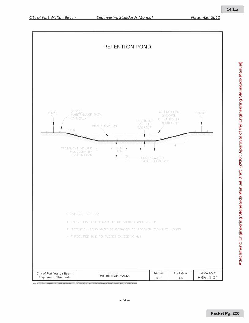
RETENTION POND
Plotted Tuesday, October 18, 2005 11:03:12 AM - C:\Users\KNITZM~1.FWB\AppData\Local\Temp\A$C00241BD9.DWG
City of Fort Walton BeachRETENTION POND
6-28-2012 DRAWING #
ESM-4.01SCALE:
KJNNTSEngineering Standards
14.1.a
Packet Pg. 226
Atta
chm
ent:
Engi
neer
ing
Stan
dard
s M
anua
l Dra
ft (2
016
: App
rova
l of t
he E
ngin
eerin
g St
anda
rds
Man
ual)

City of Fort Walton Beach Engineering Standards Manual November 2012
DETENTION POND
Plotted Tuesday, October 18, 2005 11:03:12 AM - C:\Users\KNITZM~1.FWB\AppData\Local\Temp\A$C0209419D.DWG
City of Fort Walton BeachDETENTION POND
6-28-2012 DRAWING #
ESM-4.02SCALE:
KJNNTSEngineering Standards
14.1.a
Packet Pg. 227
Atta
chm
ent:
Engi
neer
ing
Stan
dard
s M
anua
l Dra
ft (2
016
: App
rova
l of t
he E
ngin
eerin
g St
anda
rds
Man
ual)
City of Fort Walton Beach Engineering Standards Manual November 2012
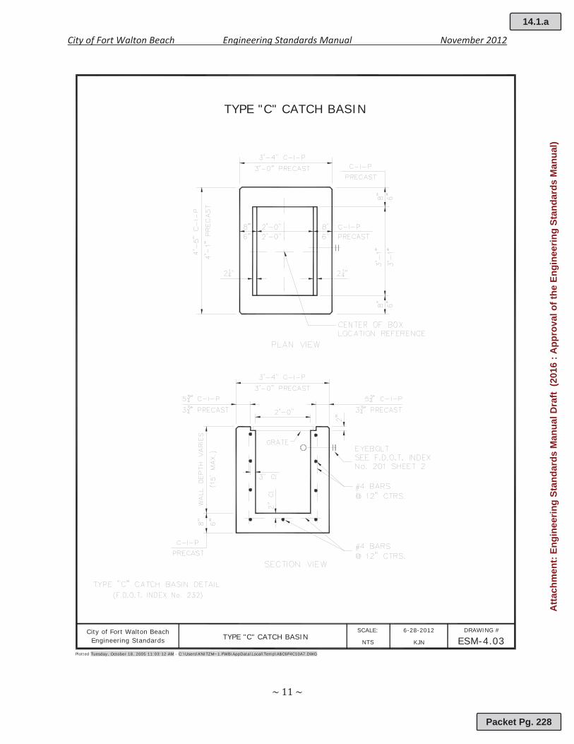
TYPE "C" CATCH BASIN
Plotted Tuesday, October 18, 2005 11:03:12 AM - C:\Users\KNITZM~1.FWB\AppData\Local\Temp\A$C6F4C10A7.DWG
City of Fort Walton BeachTYPE "C" CATCH BASIN
6-28-2012 DRAWING #
ESM-4.03SCALE:
KJNNTSEngineering Standards
14.1.a
Packet Pg. 228
Atta
chm
ent:
Engi
neer
ing
Stan
dard
s M
anua
l Dra
ft (2
016
: App
rova
l of t
he E
ngin
eerin
g St
anda
rds
Man
ual)
City of Fort Walton Beach Engineering Standards Manual November 2012
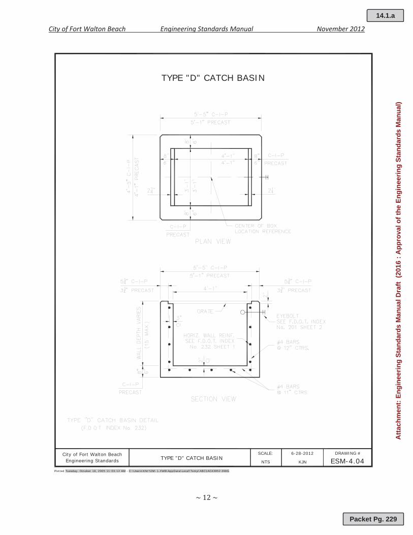
TYPE "D" CATCH BASIN
Plotted Tuesday, October 18, 2005 11:03:12 AM - C:\Users\KNITZM~1.FWB\AppData\Local\Temp\A$C1AC43852.DWG
City of Fort Walton BeachTYPE "D" CATCH BASIN
6-28-2012 DRAWING #
ESM-4.04SCALE:
KJNNTSEngineering Standards
14.1.a
Packet Pg. 229
Atta
chm
ent:
Engi
neer
ing
Stan
dard
s M
anua
l Dra
ft (2
016
: App
rova
l of t
he E
ngin
eerin
g St
anda
rds
Man
ual)
City of Fort Walton Beach Engineering Standards Manual November 2012
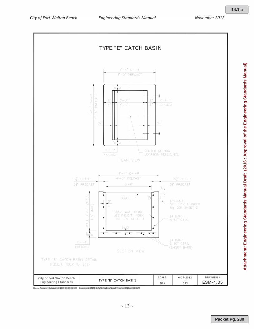
TYPE "E" CATCH BASIN
Plotted Tuesday, October 18, 2005 11:03:12 AM - C:\Users\KNITZM~1.FWB\AppData\Local\Temp\A$C720A5808.DWG
City of Fort Walton BeachTYPE "E" CATCH BASIN
6-28-2012 DRAWING #
ESM-4.05SCALE:
KJNNTSEngineering Standards
14.1.a
Packet Pg. 230
Atta
chm
ent:
Engi
neer
ing
Stan
dard
s M
anua
l Dra
ft (2
016
: App
rova
l of t
he E
ngin
eerin
g St
anda
rds
Man
ual)
City of Fort Walton Beach Engineering Standards Manual November 2012
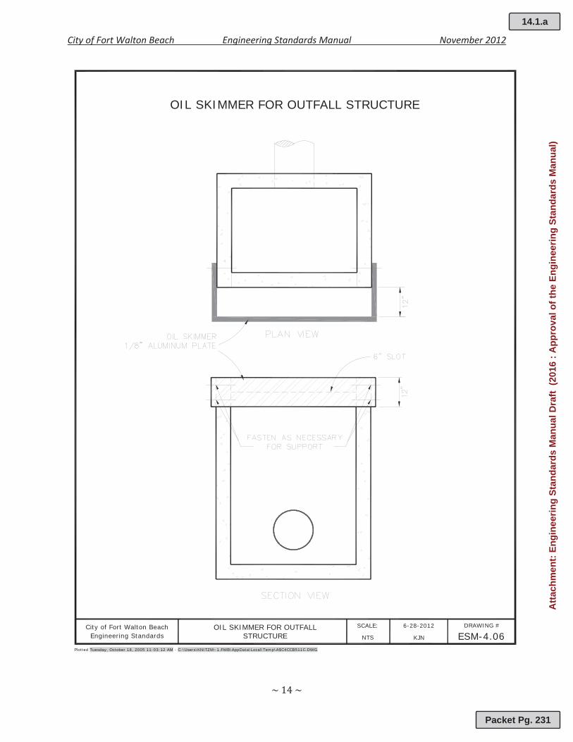
OIL SKIMMER FOR OUTFALL STRUCTURE
Plotted Tuesday, October 18, 2005 11:03:12 AM - C:\Users\KNITZM~1.FWB\AppData\Local\Temp\A$C4CCB511C.DWG
City of Fort Walton Beach OIL SKIMMER FOR OUTFALL 6-28-2012 DRAWING #
ESM-4.06SCALE:
KJNNTSEngineering Standards STRUCTURE
14.1.a
Packet Pg. 231
Atta
chm
ent:
Engi
neer
ing
Stan
dard
s M
anua
l Dra
ft (2
016
: App
rova
l of t
he E
ngin
eerin
g St
anda
rds
Man
ual)

City of Fort Walton Beach Engineering Standards Manual November 2012
MITERED END SECTION AND CONCRETE COLLAR
Plotted Tuesday, October 18, 2005 11:03:12 AM - C:\Users\KNITZM~1.FWB\AppData\Local\Temp\A$C33CC2EC9.DWG
City of Fort Walton Beach MITERED END SECTION 6-28-2012 DRAWING #
ESM-4.07SCALE:
KJNNTSEngineering Standards AND CONCRETE COLLAR
14.1.a
Packet Pg. 232
Atta
chm
ent:
Engi
neer
ing
Stan
dard
s M
anua
l Dra
ft (2
016
: App
rova
l of t
he E
ngin
eerin
g St
anda
rds
Man
ual)
City of Fort Walton Beach Engineering Standards Manual November 2012
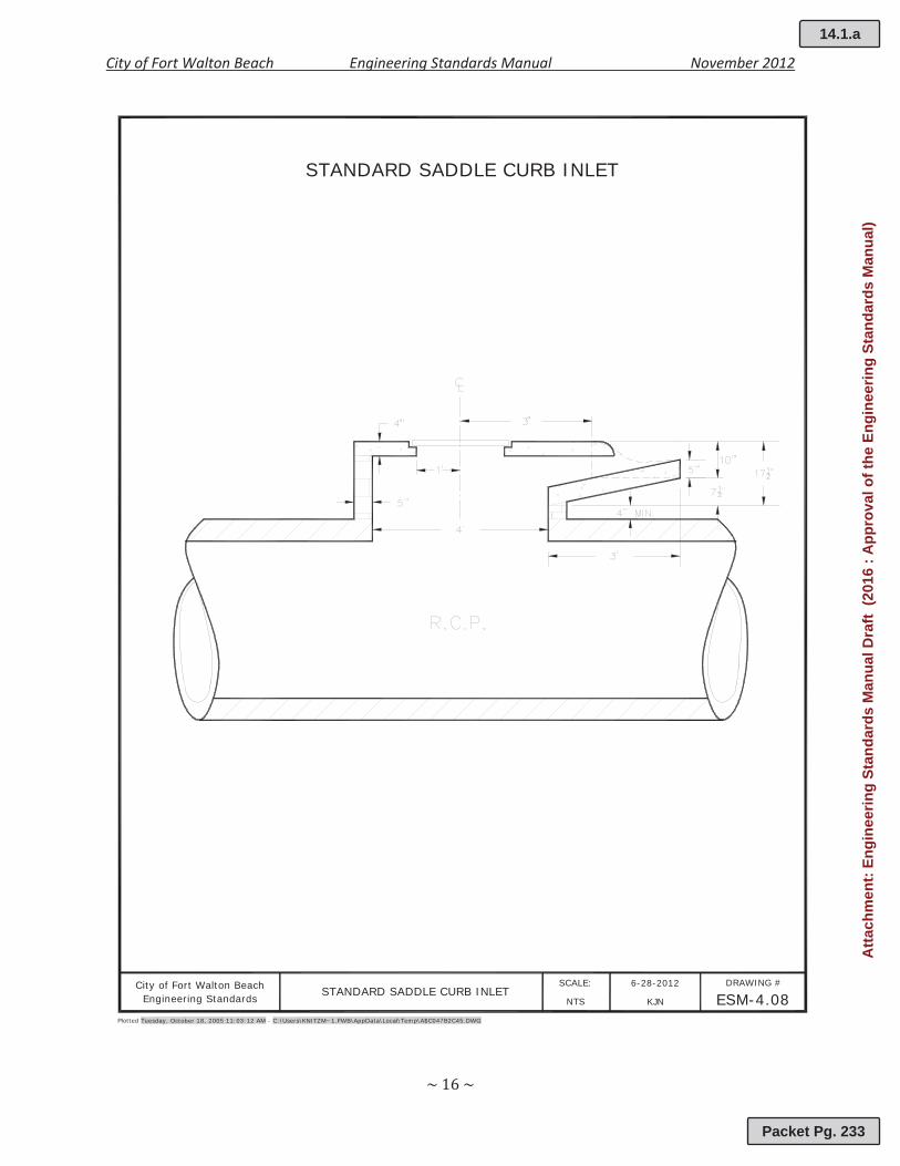
STANDARD SADDLE CURB INLET
Plotted Tuesday, October 18, 2005 11:03:12 AM - C:\Users\KNITZM~1.FWB\AppData\Local\Temp\A$C047B2C45.DWG
City of Fort Walton Beach 6-28-2012 DRAWING #
ESM-4.08SCALE:
KJNNTSEngineering StandardsSTANDARD SADDLE CURB INLET
14.1.a
Packet Pg. 233
Atta
chm
ent:
Engi
neer
ing
Stan
dard
s M
anua
l Dra
ft (2
016
: App
rova
l of t
he E
ngin
eerin
g St
anda
rds
Man
ual)

City of Fort Walton Beach Engineering Standards Manual November 2012
STANDARD FRENCH DRAIN
Plotted Tuesday, October 18, 2005 11:03:12 AM - C:\Users\KNITZM~1.FWB\AppData\Local\Temp\A$C2251152C.DWG
City of Fort Walton Beach 6-28-2012 DRAWING #
ESM-4.09SCALE:
KJNNTSEngineering Standards STANDARD FRENCH DRAIN
14.1.a
Packet Pg. 234
Atta
chm
ent:
Engi
neer
ing
Stan
dard
s M
anua
l Dra
ft (2
016
: App
rova
l of t
he E
ngin
eerin
g St
anda
rds
Man
ual)

City of Fort Walton Beach Engineering Standards Manual November 2012
STANDARD UNDERDRAIN EXFILTRATION
Plotted Tuesday, October 18, 2005 11:03:12 AM - C:\Users\KNITZM~1.FWB\AppData\Local\Temp\A$C7D377864.DWG
City of Fort Walton Beach 6-28-2012 DRAWING #
ESM-4.10SCALE:
KJNNTSEngineering Standards STANDARD UNDERDRAIN EXFILTRATION
14.1.a
Packet Pg. 235
Atta
chm
ent:
Engi
neer
ing
Stan
dard
s M
anua
l Dra
ft (2
016
: App
rova
l of t
he E
ngin
eerin
g St
anda
rds
Man
ual)

City of Fort Walton Beach Engineering Standards Manual November 2012
5.00 STREETS
5.01 Street Layout
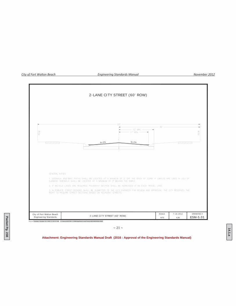
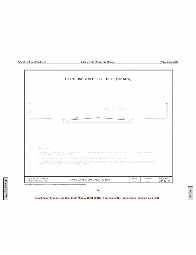
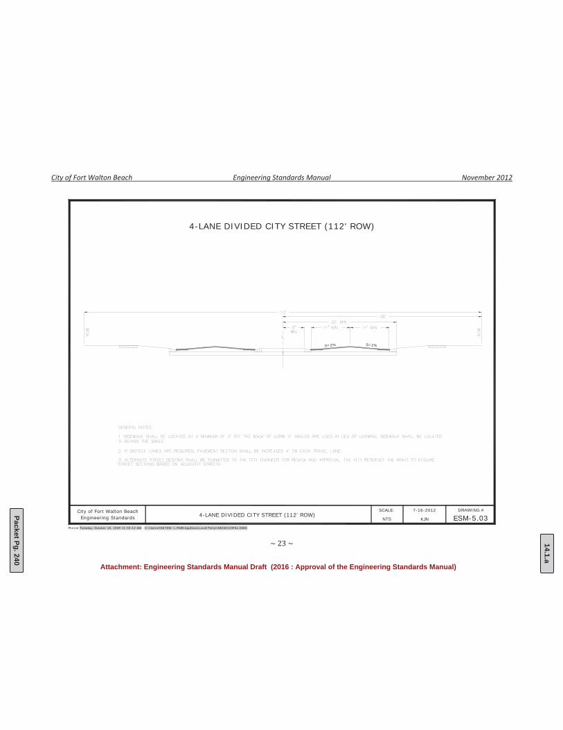
All streets within the City of Fort Walton Beach shall be designed and constructed toaccommodate vehicles, bicycles and pedestrians. The construction of state roads shall be inaccordance with the Florida Department of Transportation’s (FDOT) Standard Specificationsfor Road and Bridge Construction and FDOT Design Standards, latest edition. Theconstruction of City streets shall meet the following requirements:
a. The centerline of all roads shall be centered in the right of way. Location of the roadmay be offset from the right of way where the City determines that such changes areneeded for adequate traffic capacity, drainage, utilities, pedestrian access or other siteconstraints.
b. All travel lanes shall have a minimum lane width of eleven (11) feet measured from thecenterline of the road to the edge of pavement. One way streets shall be a minimum oftwelve (12) feet in width. Modification to existing City streets shall not result inpavement widths less than ten (10) feet in width.
c. Off Street Parking may be provided along one or both sides of a City street. Parkinglanes shall be the minimum set forth in Section 6.00
d. Bike lanes shall be clearly marked and located between the travel lane and the parkinglane or between the travel lane and the edge of pavement. Bike lanes shall be aminimum of four (4) feet in width.
e. Sidewalks are required along at least one side of all City streets.
5.02 Pavement Design
On streets and roadways within the jurisdiction of the City of Fort Walton Beach, theEngineer of Record is responsible to verify that applicable sound engineering principles areused in the structural design of flexible and rigid pavements systems. Unless otherwisenoted, all materials and workmanship shall meet Florida Department of Transportation’sFlexible Pavement Design Manual and Standard Specifications for Road and BridgeConstruction, latest edition, unless otherwise discussed herein.
a. The minimum service life of new pavement shall be twenty (20) years, while theminimum service life of rehabilitated pavements shall be ten (10) years.
b. Road base and subgrade shall be finished and prepared in accordance with Sections200, 210, 230, 204 and all sections referenced therein of the Florida Department ofTransportation Standard Specifications for Road and Bridge Construction, latest edition.
f. Vehicular surfaces shall be paved with asphalt in accordance with Sections 300, 320,330, 331 and 916 and all sections referenced therein of the Florida Department ofTransportation Standard Specifications for Road and Bridge Construction, latest edition.The City reserves the right to require additional paving or reinforcement dependingupon the type and amount of expected vehicular traffic.
c. For the construction of any new street within the City, the following tests will beprovided to the City by the contractor:
1. Compaction Test for Base Material (where applicable): One (1) for each 500square yards, but not less than one (1) in each section if the area is less than500 square yards.
14.1.a
Packet Pg. 236
Atta
chm
ent:
Engi
neer
ing
Stan
dard
s M
anua
l Dra
ft (2
016
: App
rova
l of t
he E
ngin
eerin
g St
anda
rds
Man
ual)

City of Fort Walton Beach Engineering Standards Manual November 2012
2. Asphalt Testing: One (1) set of the following tests for each 200 tons placed orone (1) set per day if less than 200 tons placed.
I. Stability, flow, unit weight, void total percentage total mix, and voidsfilled shall be determined from set of specimens prepared from eachfour hours plant operation in accordance with ASTM D 1559 and ASTMD 2726.
II. In place density tests will be performed from set (three cored samples)or each four hours plant operation; one half should be obtained atjoints.
d. Match existing curb line with cross slope of 1/4 inch per foot to center line, or asdirected by the City.
e. Hand work may be required in certain areas such as driveways, intersections, stormdrains, manholes, etc., to prevent standing water.
5.03 Curb and Gutter
The primary purpose for curbing along City streets is to convey stormwater to inlets,swales, and detention/retention areas. All curbing on streets and roads within the City ofFort Walton shall be a minimum of 3,000 psi concrete. Curb and gutter for City streets shallbe of the following type:
a. Ribbon Curbb. Drop Curbc. Square back Curbd. Rollback Curb
(This section left intentionally blank)
14.1.a
Packet Pg. 237
Atta
chm
ent:
Engi
neer
ing
Stan
dard
s M
anua
l Dra
ft (2
016
: App
rova
l of t
he E
ngin
eerin
g St
anda
rds
Man
ual)
City of Fort Walton Beach Engineering Standards Manual November 2012
S=2%S=2%
Plotted Tuesday, October 18, 2005 11:03:12 AM - C:\Users\KNITZM~1.FWB\AppData\Local\Temp\A$C00B33D9A.DWG
City of Fort Walton Beach 7-16-2012 DRAWING #
ESM-5.01SCALE:
KJNNTSEngineering Standards
2-LANE CITY STREET (60' ROW)
2-LANE CITY STREET (60' ROW)
14.1.a
Packet Pg. 238
Attachment: Engineering Standards Manual Draft (2016 : Approval of the Engineering Standards Manual)
City of Fort Walton Beach Engineering Standards Manual November 2012
S=2%
Plotted Tuesday, October 18, 2005 11:03:12 AM - C:\Users\KNITZM~1.FWB\AppData\Local\Temp\A$C309428BE.DWG
City of Fort Walton Beach 7-16-2012 DRAWING #
ESM-5.02SCALE:
KJNNTSEngineering Standards
4-LANE UNDIVIDED CITY STREET (96' ROW)
4-LANE UNDIVIDED CITY STREET (96' ROW)
S=2%
14.1.a
Packet Pg. 239
Attachment: Engineering Standards Manual Draft (2016 : Approval of the Engineering Standards Manual)
City of Fort Walton Beach Engineering Standards Manual November 2012
Plotted Tuesday, October 18, 2005 11:03:12 AM - C:\Users\KNITZM~1.FWB\AppData\Local\Temp\A$C40133FA1.DWG
City of Fort Walton Beach 7-16-2012 DRAWING #
ESM-5.03SCALE:
KJNNTSEngineering Standards
4-LANE DIVIDED CITY STREET (112' ROW)
4-LANE DIVIDED CITY STREET (112' ROW)
S=2%S=2%
14.1.a
Packet Pg. 240
Attachment: Engineering Standards Manual Draft (2016 : Approval of the Engineering Standards Manual)
City of Fort Walton Beach Engineering Standards Manual November 2012
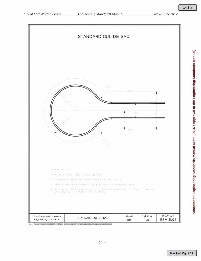
STANDARD CUL-DE-SAC
Plotted Tuesday, October 18, 2005 11:03:12 AM - C:\Users\KNITZM~1.FWB\AppData\Local\Temp\A$C34C019B9.DWG
City of Fort Walton Beach 7-11-2012 DRAWING #
ESM-5.04SCALE:
KJNNTSEngineering Standards STANDARD CUL-DE-SAC
14.1.a
Packet Pg. 241
Atta
chm
ent:
Engi
neer
ing
Stan
dard
s M
anua
l Dra
ft (2
016
: App
rova
l of t
he E
ngin
eerin
g St
anda
rds
Man
ual)
City of Fort Walton Beach Engineering Standards Manual November 2012
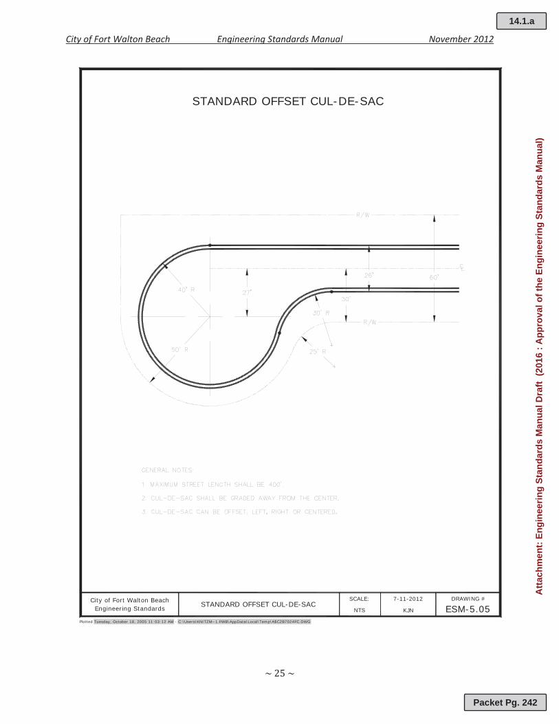
STANDARD OFFSET CUL-DE-SAC
Plotted Tuesday, October 18, 2005 11:03:12 AM - C:\Users\KNITZM~1.FWB\AppData\Local\Temp\A$C2B7024FC.DWG
City of Fort Walton Beach 7-11-2012 DRAWING #
ESM-5.05SCALE:
KJNNTSEngineering Standards STANDARD OFFSET CUL-DE-SAC
14.1.a
Packet Pg. 242
Atta
chm
ent:
Engi
neer
ing
Stan
dard
s M
anua
l Dra
ft (2
016
: App
rova
l of t
he E
ngin
eerin
g St
anda
rds
Man
ual)
City of Fort Walton Beach Engineering Standards Manual November 2012
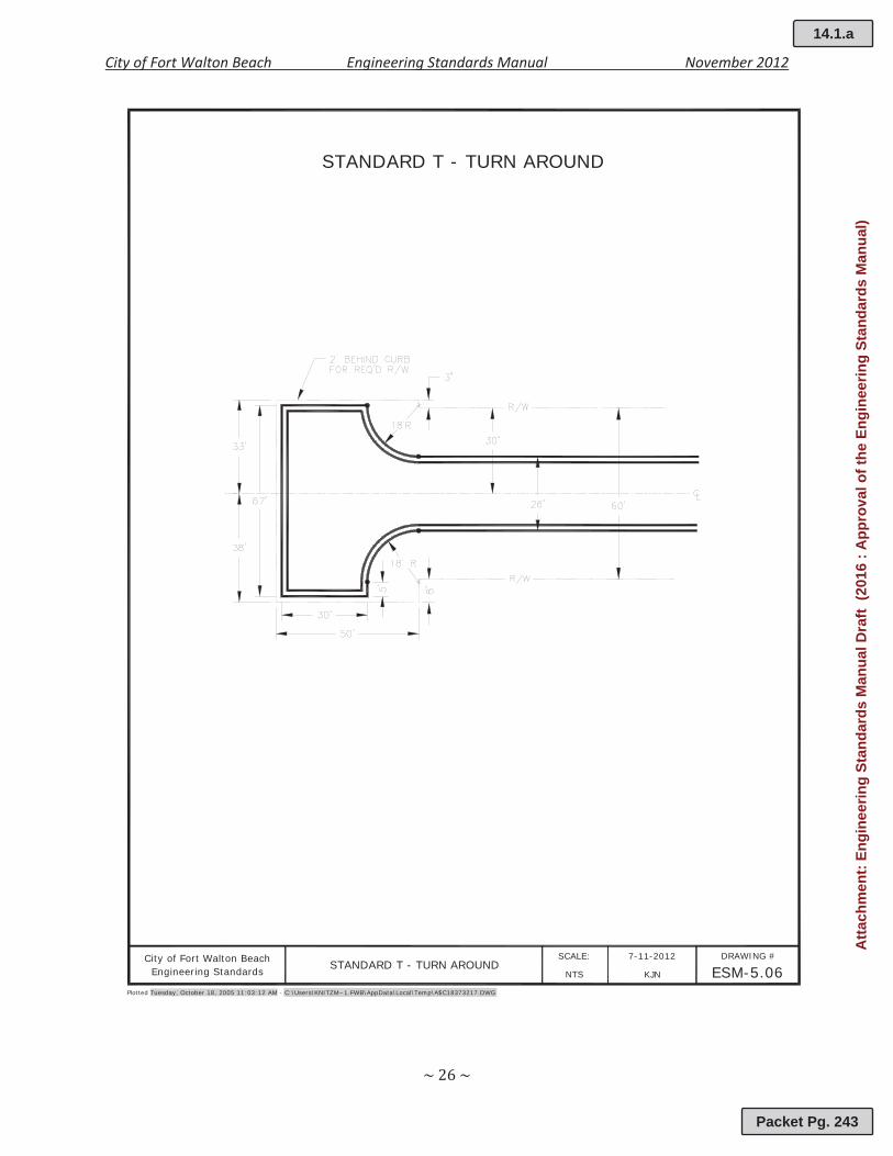
STANDARD T - TURN AROUND
Plotted Tuesday, October 18, 2005 11:03:12 AM - C:\Users\KNITZM~1.FWB\AppData\Local\Temp\A$C18373217.DWG
City of Fort Walton Beach 7-11-2012 DRAWING #
ESM-5.06SCALE:
KJNNTSEngineering Standards STANDARD T - TURN AROUND
14.1.a
Packet Pg. 243
Atta
chm
ent:
Engi
neer
ing
Stan
dard
s M
anua
l Dra
ft (2
016
: App
rova
l of t
he E
ngin
eerin
g St
anda
rds
Man
ual)

City of Fort Walton Beach Engineering Standards Manual November 2012
STANDARD 2' RIBBON CURB
Plotted Tuesday, October 18, 2005 11:03:12 AM - C:\Users\KNITZM~1.FWB\AppData\Local\Temp\A$C698F1B2C.DWG
City of Fort Walton Beach 7-11-2012 DRAWING #
ESM-5.07SCALE:
KJNNTSEngineering Standards STANDARD 2' RIBBON CURB
14.1.a
Packet Pg. 244
Atta
chm
ent:
Engi
neer
ing
Stan
dard
s M
anua
l Dra
ft (2
016
: App
rova
l of t
he E
ngin
eerin
g St
anda
rds
Man
ual)

City of Fort Walton Beach Engineering Standards Manual November 2012
STANDARD DROP CURB
Plotted Tuesday, October 18, 2005 11:03:12 AM - C:\Users\KNITZM~1.FWB\AppData\Local\Temp\A$C202D7140.DWG
City of Fort Walton Beach 7-11-2012 DRAWING #
ESM-5.08SCALE:
KJNNTSEngineering Standards STANDARD DROP CURB
14.1.a
Packet Pg. 245
Atta
chm
ent:
Engi
neer
ing
Stan
dard
s M
anua
l Dra
ft (2
016
: App
rova
l of t
he E
ngin
eerin
g St
anda
rds
Man
ual)
City of Fort Walton Beach Engineering Standards Manual November 2012
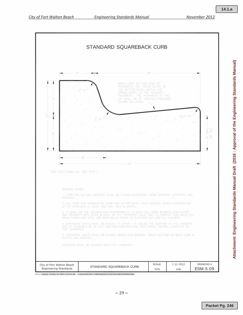
STANDARD SQUAREBACK CURB
Plotted Tuesday, October 18, 2005 11:03:12 AM - C:\Users\KNITZM~1.FWB\AppData\Local\Temp\A$C24D54B3A.DWG
City of Fort Walton Beach 7-11-2012 DRAWING #
ESM-5.09SCALE:
KJNNTSEngineering Standards STANDARD SQUAREBACK CURB
14.1.a
Packet Pg. 246
Atta
chm
ent:
Engi
neer
ing
Stan
dard
s M
anua
l Dra
ft (2
016
: App
rova
l of t
he E
ngin
eerin
g St
anda
rds
Man
ual)
City of Fort Walton Beach Engineering Standards Manual November 2012
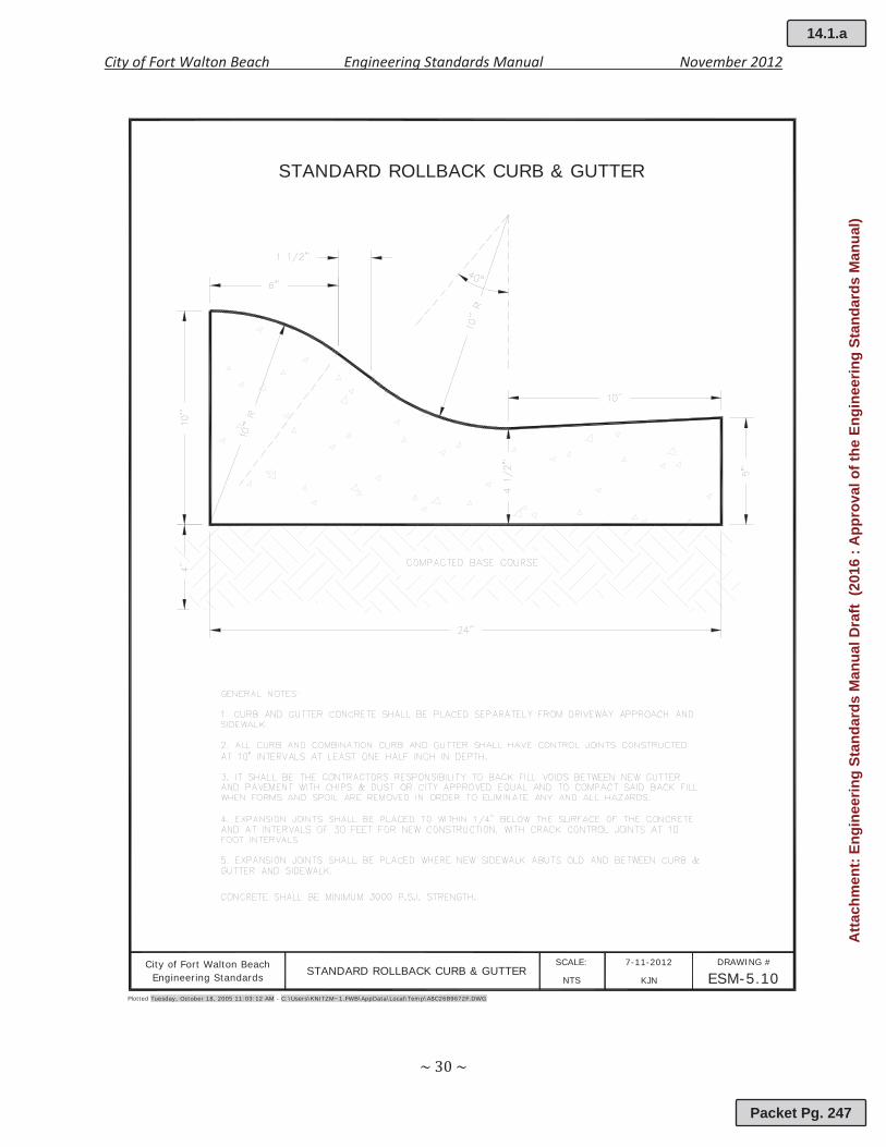
STANDARD ROLLBACK CURB & GUTTER
Plotted Tuesday, October 18, 2005 11:03:12 AM - C:\Users\KNITZM~1.FWB\AppData\Local\Temp\A$C26B9672F.DWG
City of Fort Walton Beach 7-11-2012 DRAWING #
ESM-5.10SCALE:
KJNNTSEngineering Standards STANDARD ROLLBACK CURB & GUTTER
14.1.a
Packet Pg. 247
Atta
chm
ent:
Engi
neer
ing
Stan
dard
s M
anua
l Dra
ft (2
016
: App
rova
l of t
he E
ngin
eerin
g St
anda
rds
Man
ual)
City of Fort Walton Beach Engineering Standards Manual November 2012
6.00 PARKING AND VEHICULAR ACCESSABILITY
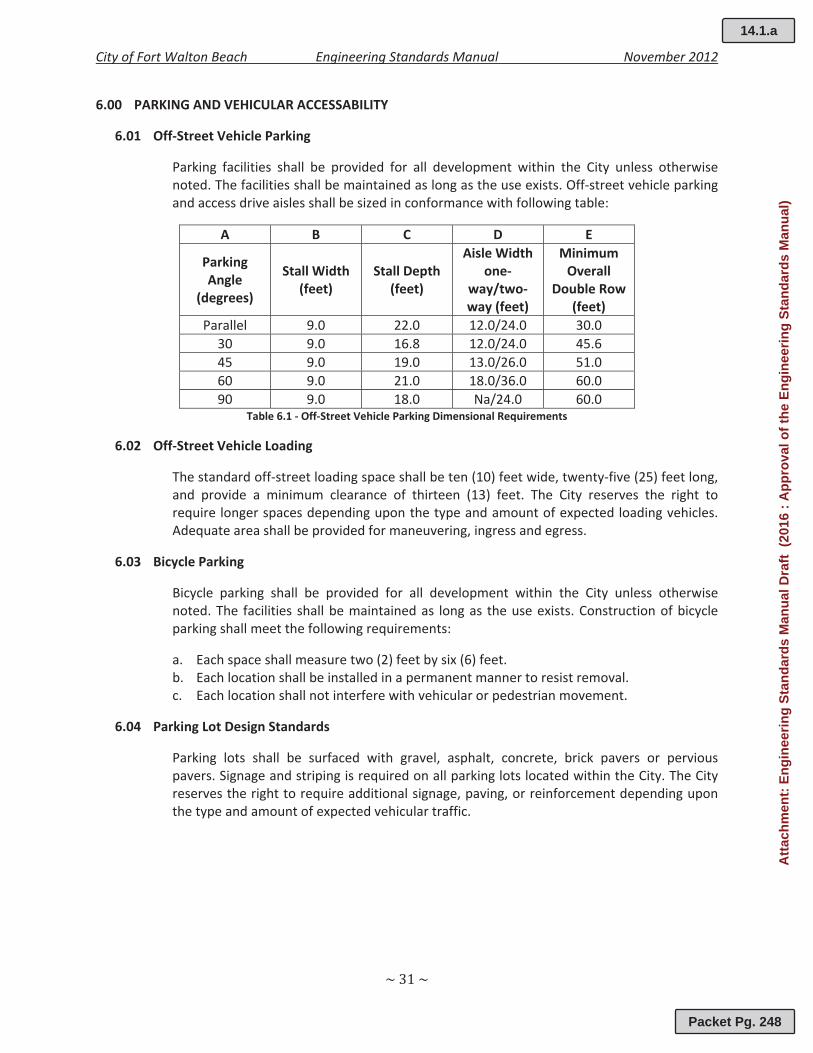
6.01 Off Street Vehicle Parking
Parking facilities shall be provided for all development within the City unless otherwisenoted. The facilities shall be maintained as long as the use exists. Off street vehicle parkingand access drive aisles shall be sized in conformance with following table:
A B C D E
ParkingAngle
(degrees)
Stall Width(feet)
Stall Depth(feet)
Aisle Widthone
way/twoway (feet)
MinimumOverall
Double Row(feet)
Parallel 9.0 22.0 12.0/24.0 30.030 9.0 16.8 12.0/24.0 45.645 9.0 19.0 13.0/26.0 51.060 9.0 21.0 18.0/36.0 60.090 9.0 18.0 Na/24.0 60.0
Table 6.1 Off Street Vehicle Parking Dimensional Requirements
6.02 Off Street Vehicle Loading
The standard off street loading space shall be ten (10) feet wide, twenty five (25) feet long,and provide a minimum clearance of thirteen (13) feet. The City reserves the right torequire longer spaces depending upon the type and amount of expected loading vehicles.Adequate area shall be provided for maneuvering, ingress and egress.
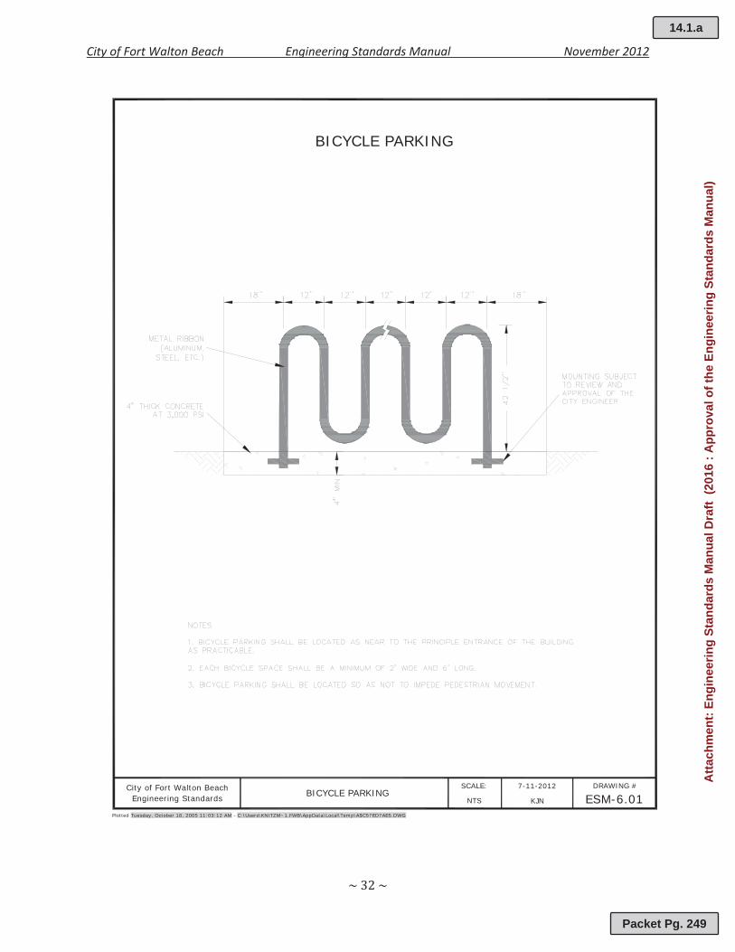
6.03 Bicycle Parking
Bicycle parking shall be provided for all development within the City unless otherwisenoted. The facilities shall be maintained as long as the use exists. Construction of bicycleparking shall meet the following requirements:
a. Each space shall measure two (2) feet by six (6) feet.b. Each location shall be installed in a permanent manner to resist removal.c. Each location shall not interfere with vehicular or pedestrian movement.
6.04 Parking Lot Design Standards
Parking lots shall be surfaced with gravel, asphalt, concrete, brick pavers or perviouspavers. Signage and striping is required on all parking lots located within the City. The Cityreserves the right to require additional signage, paving, or reinforcement depending uponthe type and amount of expected vehicular traffic.
14.1.a
Packet Pg. 248
Atta
chm
ent:
Engi
neer
ing
Stan
dard
s M
anua
l Dra
ft (2
016
: App
rova
l of t
he E
ngin
eerin
g St
anda
rds
Man
ual)
City of Fort Walton Beach Engineering Standards Manual November 2012
BICYCLE PARKING
Plotted Tuesday, October 18, 2005 11:03:12 AM - C:\Users\KNITZM~1.FWB\AppData\Local\Temp\A$C57ED7AE5.DWG
City of Fort Walton Beach 7-11-2012 DRAWING #
ESM-6.01SCALE:
KJNNTSEngineering Standards BICYCLE PARKING
14.1.a
Packet Pg. 249
Atta
chm
ent:
Engi
neer
ing
Stan
dard
s M
anua
l Dra
ft (2
016
: App
rova
l of t
he E
ngin
eerin
g St
anda
rds
Man
ual)
City of Fort Walton Beach Engineering Standards Manual November 2012
7.00 SIDEWALKS, MULTI USE PATHS, AND DRIVEWAYS
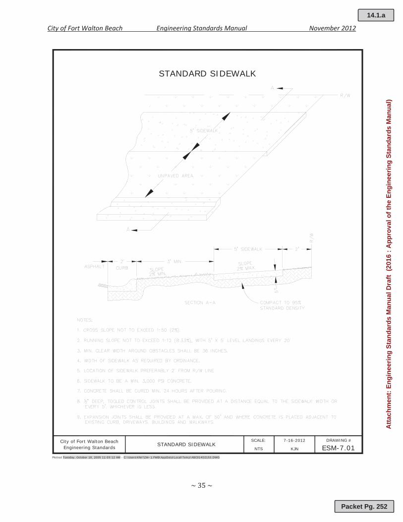
7.01 Sidewalk Design Standards
Sidewalks are required on at least one side of all City streets. All Sidewalks constructedwithin the City of Fort Walton Beach shall be constructed of a minimum of 3,000 psiconcrete and shall have a minimum concrete thickness of five (5) inches. Sidewalks locatedin state road right or way shall be in accordance with the Florida Department ofTransportation’s (FDOT) Standard Specifications for Road and Bridge Construction andFDOT Design Standards, latest edition. The City reserves the right to require apedestrian/access easement in order to accommodate sidewalks. Construction of Citysidewalk shall meet the following requirements:
d. Subgrade shall be firm and unyielding.e. The cross slope for all sidewalks shall not exceed 1:50 (2%).f. The longitudinal slope shall not exceed 1:12 (8.33%), with 5 feet x 5 feet landings every
20 feet.g. When longitudinal slopes exceed 1:12, an ADA railing and appropriate landings shall be
provided.h. Minimum clear width around obstacles shall be 36 inches.i. Concrete shall be cured a minimum of 24 hours after pouring.j. ½ inch deep, tooled control joints shall be provided at a distance equal to the sidewalk
width or very 5 feet, whichever is less.k. Expansion joints shall be provided at maximum of every fifty (50) feet and where
concrete is placed adjacent to existing curbs, driveways, buildings and walkways.
7.02 Multi Use Path Design Standards
The construction of multi use paths is encouraged on City streets where bike lanes are notfeasible. Multi use paths shall be designed and constructed to accommodate bothpedestrians and cyclists. Multi use paths constructed within the City of Fort Walton Beachshall be constructed of a minimum of 3,000 psi concrete. Multi use paths shall have aminimum concrete thickness of five (5) inches. One (1) inch of asphalt may be used as anacceptable alternative to concrete. Construction of City multi use paths shall conform tothe following guidelines:
a. Subgrade shall be firm and unyielding.b. The minimum width for all City multi use paths shall be eight (8) feet unless otherwise
noted.c. The cross slope for all multi use paths shall not exceed 1:50 (2%).d. The longitudinal slope shall not exceed 1:12 (8.33%), with 8 feet x 8 feet landings every
20 feet.e. When slopes exceed 1:12, an ADA railing and appropriate landings shall be provided.f. Minimum clear width around obstacles shall be 36 inches.g. Concrete shall be cured a minimum of 24 hours after pouring.h. ½ inch deep, tooled control joints shall be provided at a distance equal to the multi use
path width or every 8 feet, whichever is less.i. Expansion joints shall be provided at maximum of every fifty (50) feet and where
concrete is placed adjacent to existing curbs, driveways, buildings and walkways.
14.1.a
Packet Pg. 250
Atta
chm
ent:
Engi
neer
ing
Stan
dard
s M
anua
l Dra
ft (2
016
: App
rova
l of t
he E
ngin
eerin
g St
anda
rds
Man
ual)

City of Fort Walton Beach Engineering Standards Manual November 2012
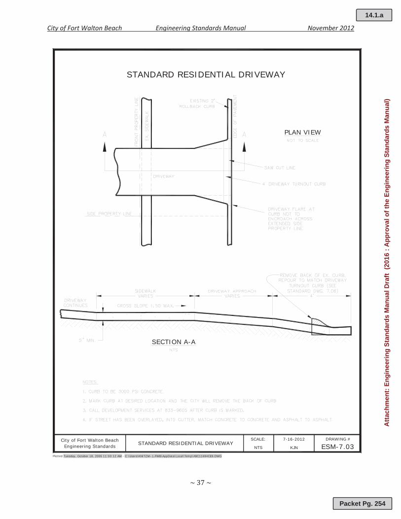
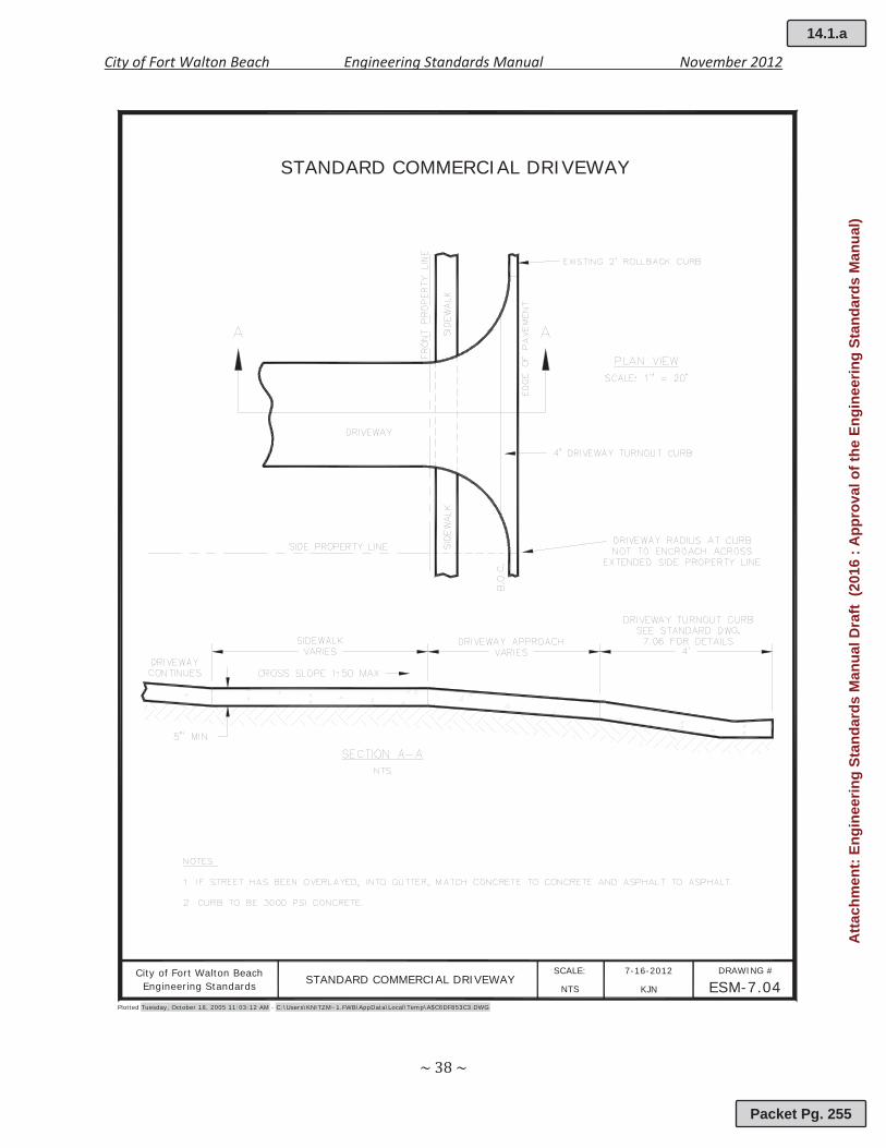
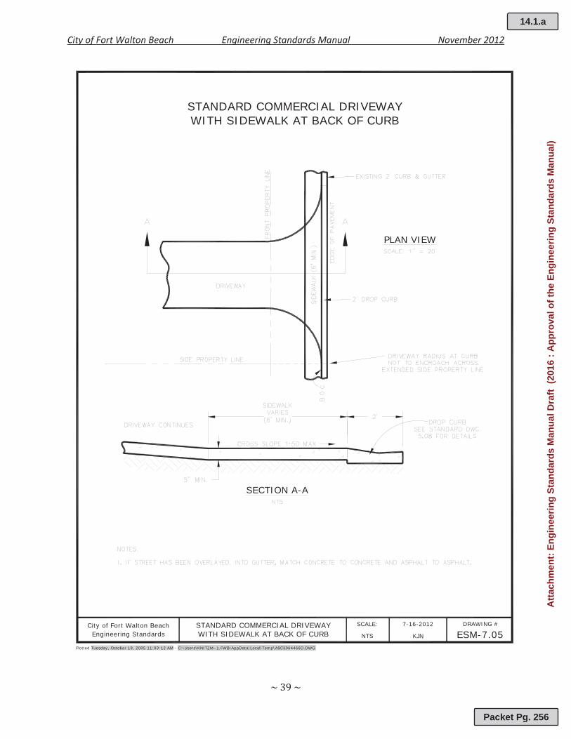
7.03 Driveway Design Standards
All driveways constructed within the City of Fort Walton Beach shall be paved from the edge ofpavement to the City right of way line. Driveways shall be constructed of a minimum of 3,000psi concrete or asphalt pavement. Driveways shall have a minimum thickness of five (5) inchesfor concrete pavements, and a minimum of one and one half (1 ½) inches for asphaltpavement. Driveways connecting to state road right or way shall be in accordance with theFlorida Department of Transportation’s (FDOT) Standard Specifications for Road and BridgeConstruction and FDOT Design Standards, latest edition. The City reserves the right to requireadditional paving or reinforcement depending upon the type and amount of expectedvehicular traffic. Construction of City driveways shall conform to the following guidelines:
a. Subgrade shall be firm and unyielding.b. The maximum width of the driveway shall be twenty four (24) feet unless the City
determines that a wider driveway would provide safer access.c. For driveways that intersect City sidewalk, the cross slope of a five (5) foot wide section is
to not exceed 1:50 (2%). Longitudinal slope not to exceed 1:12 (8.33%).d. Concrete shall be cured a minimum of 24 hours after pouring.e. Expansion joints shall be provided where concrete is placed adjacent to the existing curb,
driveways, buildings and walkways.f. If street has been overlaid into the gutter, match concrete to concrete and asphalt to
asphalt.
(This section left intentionally blank)
14.1.a
Packet Pg. 251
Atta
chm
ent:
Engi
neer
ing
Stan
dard
s M
anua
l Dra
ft (2
016
: App
rova
l of t
he E
ngin
eerin
g St
anda
rds
Man
ual)
City of Fort Walton Beach Engineering Standards Manual November 2012
STANDARD SIDEWALK
Plotted Tuesday, October 18, 2005 11:03:12 AM - C:\Users\KNITZM~1.FWB\AppData\Local\Temp\A$C014D2153.DWG
City of Fort Walton Beach 7-16-2012 DRAWING #
ESM-7.01SCALE:
KJNNTSEngineering Standards STANDARD SIDEWALK
14.1.a
Packet Pg. 252
Atta
chm
ent:
Engi
neer
ing
Stan
dard
s M
anua
l Dra
ft (2
016
: App
rova
l of t
he E
ngin
eerin
g St
anda
rds
Man
ual)

City of Fort Walton Beach Engineering Standards Manual November 2012
MULTI-USE PATH
Plotted Tuesday, October 18, 2005 11:03:12 AM - C:\Users\KNITZM~1.FWB\AppData\Local\Temp\A$C67A8769A.DWG
City of Fort Walton Beach 7-16-2012 DRAWING #
ESM-7.02SCALE:
KJNNTSEngineering Standards MULTI-USE PATH
14.1.a
Packet Pg. 253
Atta
chm
ent:
Engi
neer
ing
Stan
dard
s M
anua
l Dra
ft (2
016
: App
rova
l of t
he E
ngin
eerin
g St
anda
rds
Man
ual)
City of Fort Walton Beach Engineering Standards Manual November 2012
SECTION A-A
PLAN VIEW
STANDARD RESIDENTIAL DRIVEWAY
Plotted Tuesday, October 18, 2005 11:03:12 AM - C:\Users\KNITZM~1.FWB\AppData\Local\Temp\A$C11694CE9.DWG
City of Fort Walton Beach 7-16-2012 DRAWING #
ESM-7.03SCALE:
KJNNTSEngineering Standards STANDARD RESIDENTIAL DRIVEWAY
14.1.a
Packet Pg. 254
Atta
chm
ent:
Engi
neer
ing
Stan
dard
s M
anua
l Dra
ft (2
016
: App
rova
l of t
he E
ngin
eerin
g St
anda
rds
Man
ual)
City of Fort Walton Beach Engineering Standards Manual November 2012
STANDARD COMMERCIAL DRIVEWAY
Plotted Tuesday, October 18, 2005 11:03:12 AM - C:\Users\KNITZM~1.FWB\AppData\Local\Temp\A$C6DF853C3.DWG
City of Fort Walton Beach 7-16-2012 DRAWING #
ESM-7.04SCALE:
KJNNTSEngineering Standards STANDARD COMMERCIAL DRIVEWAY
14.1.a
Packet Pg. 255
Atta
chm
ent:
Engi
neer
ing
Stan
dard
s M
anua
l Dra
ft (2
016
: App
rova
l of t
he E
ngin
eerin
g St
anda
rds
Man
ual)
City of Fort Walton Beach Engineering Standards Manual November 2012
PLAN VIEW
SECTION A-A
Plotted Tuesday, October 18, 2005 11:03:12 AM - C:\Users\KNITZM~1.FWB\AppData\Local\Temp\A$C3064466D.DWG
City of Fort Walton Beach 7-16-2012 DRAWING #
ESM-7.05SCALE:
KJNNTSEngineering Standards
STANDARD COMMERCIAL DRIVEWAYWITH SIDEWALK AT BACK OF CURB
STANDARD COMMERCIAL DRIVEWAYWITH SIDEWALK AT BACK OF CURB
14.1.a
Packet Pg. 256
Atta
chm
ent:
Engi
neer
ing
Stan
dard
s M
anua
l Dra
ft (2
016
: App
rova
l of t
he E
ngin
eerin
g St
anda
rds
Man
ual)
City of Fort Walton Beach Engineering Standards Manual November 2012
Plotted Tuesday, October 18, 2005 11:03:12 AM - C:\Users\KNITZM~1.FWB\AppData\Local\Temp\A$C075D5449.DWG
City of Fort Walton Beach 7-16-2012 DRAWING #
ESM-7.06SCALE:
KJNNTSEngineering Standards
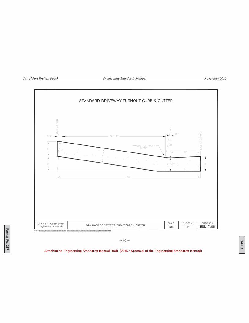
STANDARD DRIVEWAY TURNOUT CURB & GUTTER
STANDARD DRIVEWAY TURNOUT CURB & GUTTER
14.1.a
Packet Pg. 257
Attachment: Engineering Standards Manual Draft (2016 : Approval of the Engineering Standards Manual)
City of Fort Walton Beach Engineering Standards Manual November 2012
8.00 ROADSIDE APPENDITURES
8.01 Solid Waste Receptacle Pads
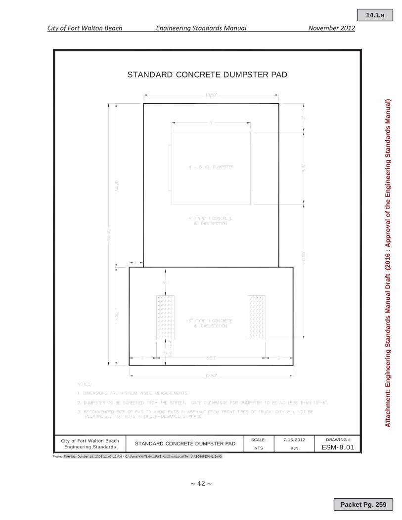
Solid Waste Receptacles shall be located in an accessible area determined by the City of FortWalton Beach’s Sanitation Department. Receptacle pads constructed within the City shall beconstructed of a minimum of 3,000 psi concrete and shall be a minimum of six (6) inchesthick. Solid waste receptacle pads and enclosures shall conform to the followingrequirements:
a. Subgrade shall be firm and unyielding.b. Concrete shall be cured a minimum of 24 hours after pouring.c. Expansion joints shall be provided where concrete is placed adjacent to the existing curb,
driveways, buildings and walkways.d. All receptacles shall be screened from the street.e. Gate clearance for the dumpster to be no less than 10’ 6”.
(This section left intentionally blank)
14.1.a
Packet Pg. 258
Atta
chm
ent:
Engi
neer
ing
Stan
dard
s M
anua
l Dra
ft (2
016
: App
rova
l of t
he E
ngin
eerin
g St
anda
rds
Man
ual)
City of Fort Walton Beach Engineering Standards Manual November 2012
Plotted Tuesday, October 18, 2005 11:03:12 AM - C:\Users\KNITZM~1.FWB\AppData\Local\Temp\A$C645E4042.DWG
City of Fort Walton Beach 7-16-2012 DRAWING #
ESM-8.01SCALE:
KJNNTSEngineering StandardsSTANDARD CONCRETE DUMPSTER PAD
STANDARD CONCRETE DUMPSTER PAD
14.1.a
Packet Pg. 259
Atta
chm
ent:
Engi
neer
ing
Stan
dard
s M
anua
l Dra
ft (2
016
: App
rova
l of t
he E
ngin
eerin
g St
anda
rds
Man
ual)
City of Fort Walton Beach Engineering Standards Manual November 2012
9.00 Utilities
9.01 Utility Easements
All potable water, sanitary sewer, drainage, and reclaimed water system improvementsshall be constructed within the right of way, platted easement, dedicated easement, or onproperty owned by the City of Fort Walton Beach. The City requires a utility easement forall utilities located outside the City right of way that are to be maintained by the City. Allutility easements for City infrastructure shall meet the following requirements:
a. Utility easements on plats shall be marked clearly and referenced from the right of wayand property lines. Dedication of the platted utility easement shall be shown on theplat and include any and all restrictions.
b. In circumstances where deeded utility easements are required, a utility easement shallbe prepared by a Florida Registered Land Surveyor and shall include a sketch and legaldescription.
c. Utility easements shall be for a specific purpose and permanent in nature.d. No structures or other physical barriers are permitted within the easement unless
otherwise approved by the City of Fort Walton Beach.e. Widths of utility easements shall be no less than three (3) times the depth of the pipe
or a minimum of ten (10) feet for potable water, sanitary sewer, drainage andreclaimed water. The City reserves the right to request a larger utility easementdepending on the proposed pipe depth, physical constraints, and environmentalconditions.
9.02 Potable Water
All potable water lines constructed within the City of Fort Walton Beach shall be installedwith a minimum vertical cover of thirty (30) inches. Potable water lines shall be located atleast ten (10) feet horizontally away from sanitary sewer or reclaimed water or currentFDEP standards. Where crossing under sanitary sewer, potable water lines shall have atleast eighteen (18) inches of vertical separation. In situations where vertical and/orhorizontal clearances are not met, the main shall be encased in concrete. Construction ofpotable water lines shall meet the following specifications listed below and in Appendix9A..
a. Pipe: All pipe used for the water distribution system shall be of the PVC (C900) orductile iron variety.
1. Polyvinyl Chloride pipe shall meet the requirements set forth in AWWA C900and shall be cell class 12454 per ASTM D1784. Plastic pipe and fittings shallbear the seal of the National Sanitation Foundation (NSF) for potable waterservice.
2. Ductile iron pipe shall meet the requirements set forth in AWWA C150 andC151.
b. Fittings: All fittings shall be ductile iron and meet the requirements set forth in AWWAC110, C111, and C153. Fittings shall be complete with gaskets, follower glands, alloysteel tee bolts and hex nuts. Retainer glands shall be made of ductile iron and shallmeet the requirements set forth in ASTM A536. Dimensions of the gland shall be suchthat it conforms to mechanical joint requirements set forth in AWWA C111 and C153.
14.1.a
Packet Pg. 260
Atta
chm
ent:
Engi
neer
ing
Stan
dard
s M
anua
l Dra
ft (2
016
: App
rova
l of t
he E
ngin
eerin
g St
anda
rds
Man
ual)
City of Fort Walton Beach Engineering Standards Manual November 2012
c. Tracer Wire: Detection wire shall be insulated single strand, solid copper with aminimum of 12 AWG. A continuous length of tracer wire shall be wrapped around thelength of all nonmetallic pipes.
d. Valves and Valve Boxes: Valves shall be of the resilient seat type and shall conform tothe requirements set forth in AWWA C509 and C515. Openings shall be in thecounterclockwise direction. Valve boxes shall be cast iron and of the adjustable variety.A traffic rated valve box shall accompany every valve.
e. Tapping Sleeves and Tapping Valves:1. Tapping sleeves shall be of the non restrainable type and shall have a 17 7 type
304 stainless steel body. All associated hardware shall be stainless steel.2. Tapping valves shall be of the ductile iron type and meet the requirements set
forth in AWWA C509. Valves shall be full port opening to accept shell cuttersand shall be provided with an alignment ring.
f. Corporation Stops: Corporation stops shall be either ground key or ball corporationvariety and shall conform to the requirements set forth in AWWA C800.
g. Service Saddle: Service saddles shall be designed to provide a drip tight connection andmade of a corrosion resistant material. All service saddles shall be fitting with a highpressure gasket.
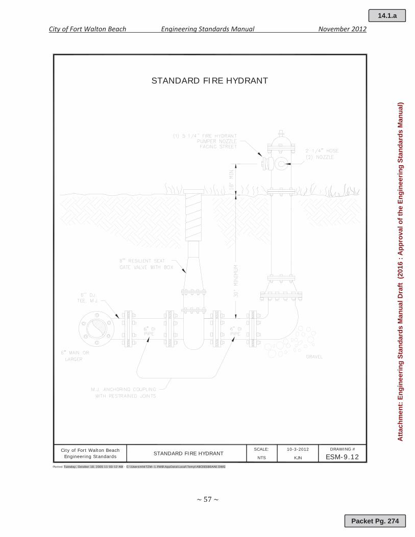
h. Fire Hydrants: Fire hydrants shall be manufactured by American Cast Iron PipeCompany©. Fire hydrants shall meet the requirements set forth in AWWA C502 andhave a three (3) way nozzle with a 5 ¼” Valve.
i. Services: Water services shall be either of the polyethylene or copper variety. Allpolyethylene water services shall meet the requirements set forth in AWWA C901 C. Allcopper tubing shall conform to ASTM B 88 96 and be of the Type K, soft variety.
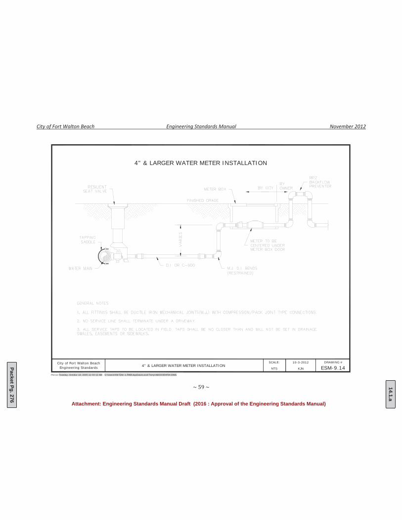
j. Meters: Water meters shall be manufactured by Hersey Meter Company©. Watermeters size ¾” to 2” shall be of the positive displacement type and shall have drive byread capabilities. Water meters 4” and above shall be of the compound type and shallhave drive by capabilities.
k. Backflow Prevention Devices: All backflow preventers shall meet the requirements setforth in AWWA C510 and C511.Residential backflows shall be of the in ground dualcheck type. Commercial backflows shall be of the reduced pressure (RPZ) type. Allbackflows shall be located on the customer side of the meter and are the responsibilityof the owner.
9.03 Sanitary Sewer
All sanitary sewer components constructed within the City of Fort Walton Beach shall belocated in the center of the road. The minimum horizontal clearance between water andsewer lines shall be ten (10) feet minimum or current FDEP standards. The minimumvertical clearance with a water line shall be eighteen (18) inches or current FDEP standards.Sewer lines shall be located below the water lines. Construction of sanitary sewercomponents shall meet the following specifications listed below and in Figure 9.2.
a. Pipe: All pipe used for the sanitary sewer system shall be of the PVC (SDR 35) or ductileiron variety.
1. Polyvinyl Chloride gravity sewer pipe shall be of the SDR 35 type and meet therequirements of cell class 12454 per ASTM D1784. Pipe sizes 4” – 15” shallmeet the requirements of ASTM D3034. Seals shall meet the requirement setforth in ASTM F477.
14.1.a
Packet Pg. 261
Atta
chm
ent:
Engi
neer
ing
Stan
dard
s M
anua
l Dra
ft (2
016
: App
rova
l of t
he E
ngin
eerin
g St
anda
rds
Man
ual)

City of Fort Walton Beach Engineering Standards Manual November 2012
2. Ductile iron pipe shall be used for pressurized sanitary sewer systems and meetthe requirements set forth in ASTM A 746. Ductile iron pipe shall be push onjoint and fittings shall be supplied from the same manufacturer. All pipes shallbe protected with a City approved coating.
b. Fittings: Fittings for gravity sewer pipe shall be plastic and shall conform torequirements set forth in ASTM D2680. Fittings for pressurized pipe shall be ductile ironand meet the requirements set forth in ANSI A21.1.
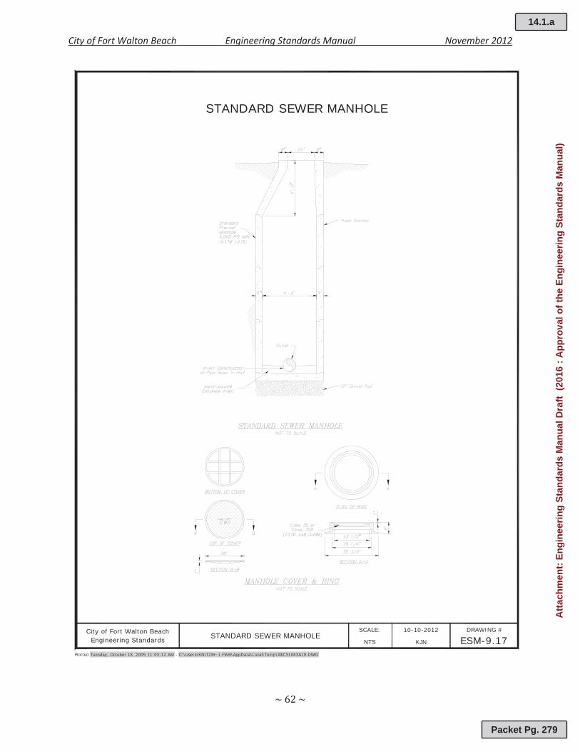
c. Precast Manholes: Precast concrete manhole risers, base sections, and tops shallconform to ASTM C478. The minimum compressive strength of the concrete shall be4,000 psi. Cast in place manholes shall not be used unless previously authorized by theCity.
d. Frames, Covers, and Grates: Manhole frames, covers, and gratings shall comply withASTM A48/A48M and shall be Class 35 gray iron, or Class 35B ductile iron unlessotherwise indicated. Manholes in vehicular traffic areas shall be rated for H 20 loading.
9.04 Drainage
Drainage components constructed within the City of Fort Walton Beach shall be installedwith a minimum vertical cover of twenty four (30) inches. The minimum vertical clearancewith water and sewer shall be eighteen (18) inches or current FDEP standards. Unlessotherwise directed, all stormwater pipe located within the City right of way shall bereinforced concrete pipe. Alternate material may be used outside the of the City right ofway. The use of corrugated metal pipe for drainage purposes is prohibited. Construction ofdrainage system components shall meet the following specifications listed in Appendix 9A.
9.05 Reclaimed Water (reserved for future use)
9.06 Utility As builts
Upon completion of utility installation that the City will maintain, the Contractor shallproduce and submit signed and sealed record drawings/as builts produced by a FloridaRegistered Land Surveyor. The amount of detail on the record drawings shall include but isnot limited to graphic scale, manhole rim and invert elevations, pipe material, pipe size,percent slope, location of appurtenances, and any other information deemed necessary bythe City. The acceptance of the record drawings by the City does not release the Contractorfrom the liability of the construction. The City reserves the right to verify the recorddrawings/as builts prior to acceptance.
(This section left intentionally blank)
14.1.a
Packet Pg. 262
Atta
chm
ent:
Engi
neer
ing
Stan
dard
s M
anua
l Dra
ft (2
016
: App
rova
l of t
he E
ngin
eerin
g St
anda
rds
Man
ual)
City of Fort Walton Beach Engineering Standards Manual November 2012
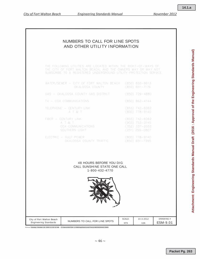
48 HOURS BEFORE YOU DIGCALL SUNSHINE STATE ONE CALL
1-800-432-4770
City of Fort Walton BeachNUMBERS TO CALL FOR LINE SPOTS
10-3-2012 DRAWING #
ESM-9.01SCALE:
KJN
NUMBERS TO CALL FOR LINE SPOTSAND OTHER UTILITY INFORMATION
Plotted Tuesday, October 18, 2005 11:03:12 AM - C:\Users\KNITZM~1.FWB\AppData\Local\Temp\A$C582D6A42.DWG
NTSEngineering Standards
14.1.a
Packet Pg. 263
Atta
chm
ent:
Engi
neer
ing
Stan
dard
s M
anua
l Dra
ft (2
016
: App
rova
l of t
he E
ngin
eerin
g St
anda
rds
Man
ual)
City of Fort Walton Beach Engineering Standards Manual November 2012
Plotted Tuesday, October 18, 2005 11:03:12 AM - C:\Users\KNITZM~1.FWB\AppData\Local\Temp\A$C4021795A.DWG
City of Fort Walton Beach 10-3-2012 DRAWING #
ESM-9.02SCALE:
KJNNTSEngineering Standards
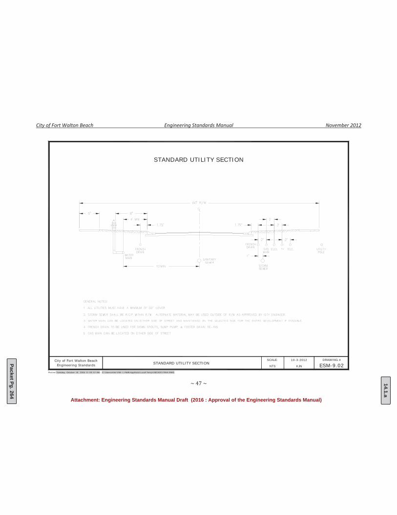
STANDARD UTILITY SECTION
STANDARD UTILITY SECTION
14.1.a
Packet Pg. 264
Attachment: Engineering Standards Manual Draft (2016 : Approval of the Engineering Standards Manual)
City of Fort Walton Beach Engineering Standards Manual November 2012
Plotted Tuesday, October 18, 2005 11:03:12 AM - C:\Users\KNITZM~1.FWB\AppData\Local\Temp\A$C580917D2.DWG
City of Fort Walton Beach 10-3-2012 DRAWING #
ESM-9.03SCALE:
KJNNTSEngineering Standards
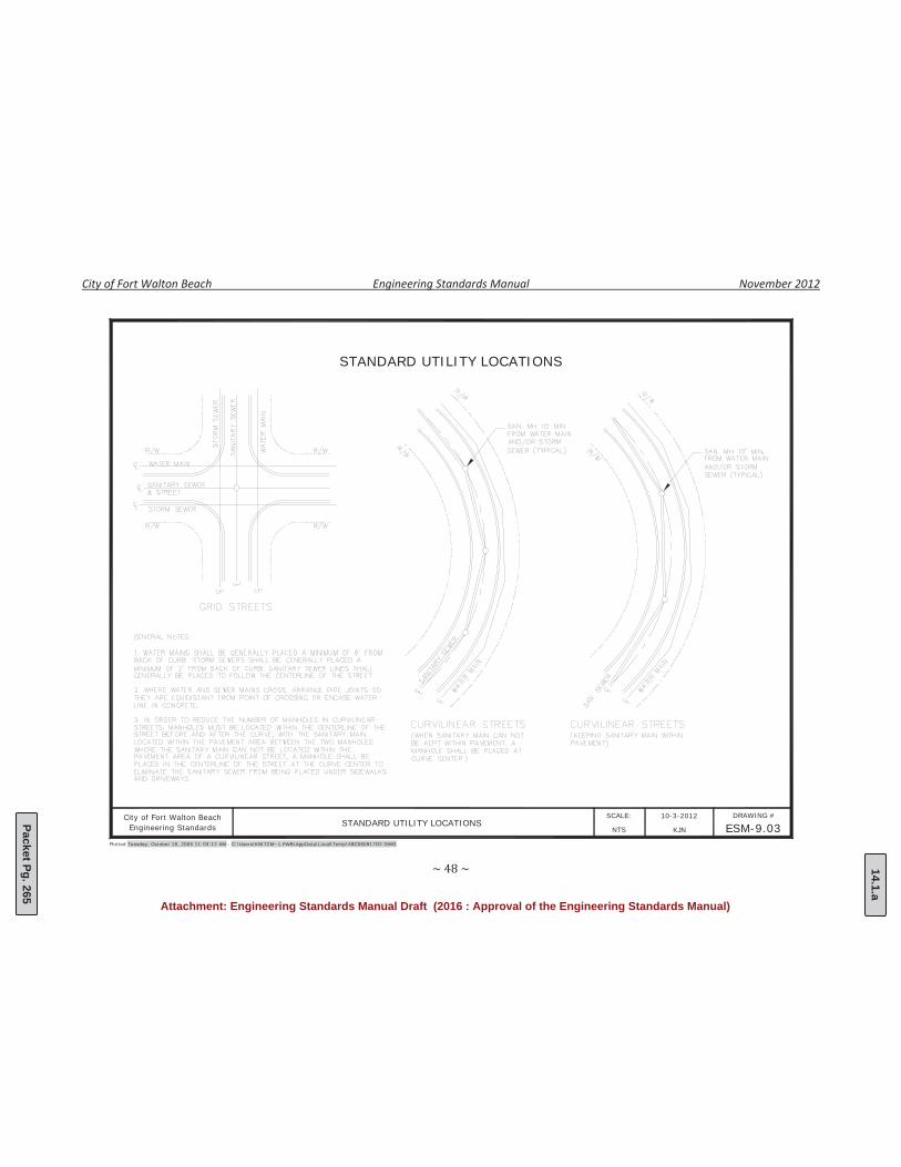
STANDARD UTILITY LOCATIONS
STANDARD UTILITY LOCATIONS
14.1.a
Packet Pg. 265
Attachment: Engineering Standards Manual Draft (2016 : Approval of the Engineering Standards Manual)
City of Fort Walton Beach Engineering Standards Manual November 2012
City of Fort Walton Beach WATER & SEWER MAIN 10-3-2012 DRAWING #
ESM-9.04SCALE:
KJN
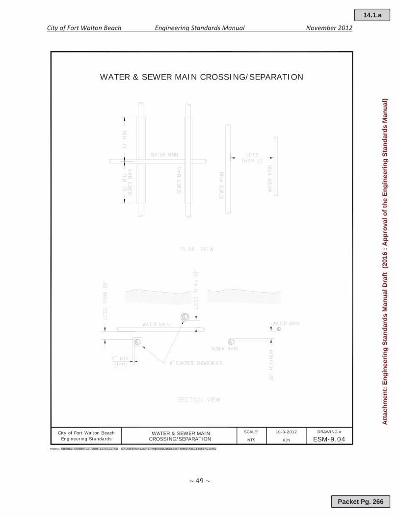
WATER & SEWER MAIN CROSSING/SEPARATION
Plotted Tuesday, October 18, 2005 11:03:12 AM - C:\Users\KNITZM~1.FWB\AppData\Local\Temp\A$C115562A0.DWG
NTSEngineering Standards CROSSING/SEPARATION
14.1.a
Packet Pg. 266
Atta
chm
ent:
Engi
neer
ing
Stan
dard
s M
anua
l Dra
ft (2
016
: App
rova
l of t
he E
ngin
eerin
g St
anda
rds
Man
ual)

City of Fort Walton Beach Engineering Standards Manual November 2012
City of Fort Walton Beach TYPICAL RECLAIMED 10-3-2012 DRAWING #
ESM-9.05SCALE:
KJN
TYPICAL RECLAIMED WATER/POTABLE WATER CROSSING
Plotted Tuesday, October 18, 2005 11:03:12 AM - C:\Users\KNITZM~1.FWB\AppData\Local\Temp\A$C6D24373B.DWG
NTSEngineering Standards WATER/POTABLE WATER CROSSING
14.1.a
Packet Pg. 267
Atta
chm
ent:
Engi
neer
ing
Stan
dard
s M
anua
l Dra
ft (2
016
: App
rova
l of t
he E
ngin
eerin
g St
anda
rds
Man
ual)
City of Fort Walton Beach Engineering Standards Manual November 2012
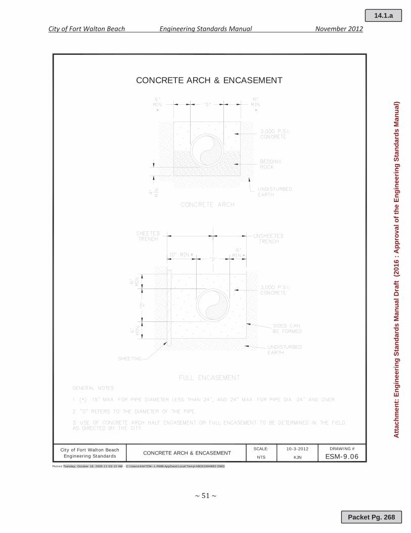
City of Fort Walton Beach CONCRETE ARCH & ENCASEMENT 10-3-2012 DRAWING #
ESM-9.06SCALE:
KJN
CONCRETE ARCH & ENCASEMENT
Plotted Tuesday, October 18, 2005 11:03:12 AM - C:\Users\KNITZM~1.FWB\AppData\Local\Temp\A$C61684BE2.DWG
NTSEngineering Standards
14.1.a
Packet Pg. 268
Atta
chm
ent:
Engi
neer
ing
Stan
dard
s M
anua
l Dra
ft (2
016
: App
rova
l of t
he E
ngin
eerin
g St
anda
rds
Man
ual)
City of Fort Walton Beach Engineering Standards Manual November 2012
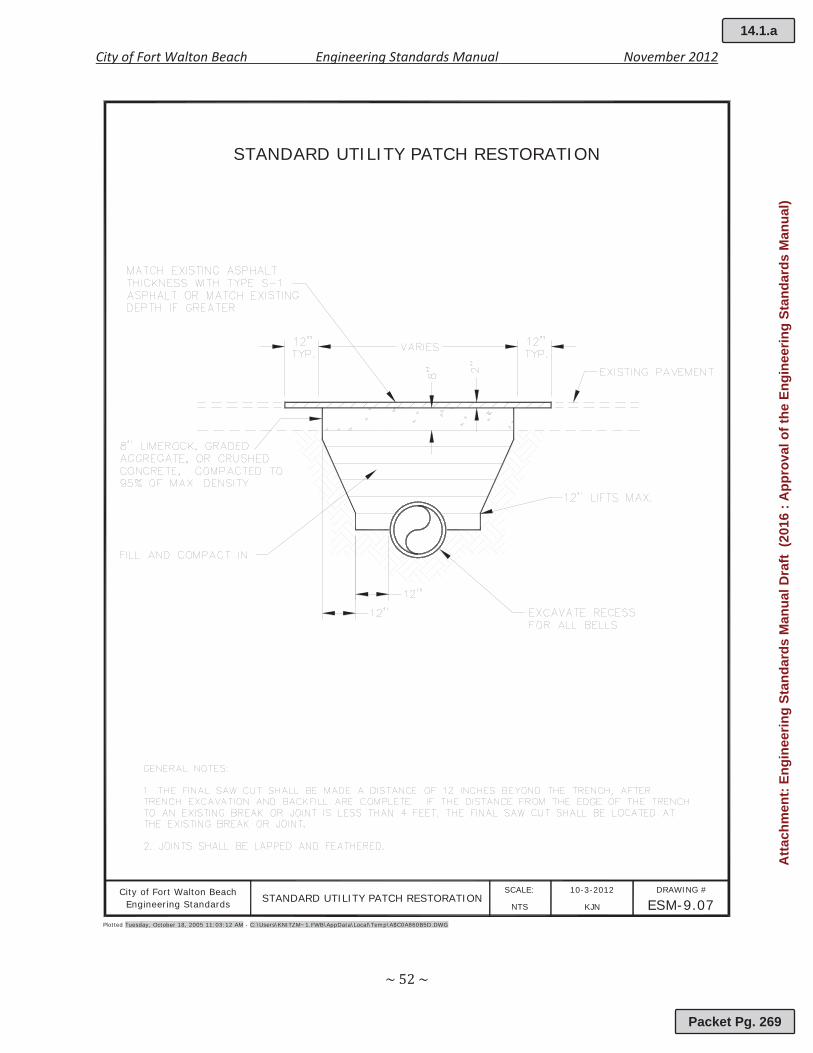
City of Fort Walton Beach STANDARD UTILITY PATCH RESTORATION 10-3-2012 DRAWING #
ESM-9.07SCALE:
KJN
STANDARD UTILITY PATCH RESTORATION
Plotted Tuesday, October 18, 2005 11:03:12 AM - C:\Users\KNITZM~1.FWB\AppData\Local\Temp\A$C0A860B5D.DWG
NTSEngineering Standards
14.1.a
Packet Pg. 269
Atta
chm
ent:
Engi
neer
ing
Stan
dard
s M
anua
l Dra
ft (2
016
: App
rova
l of t
he E
ngin
eerin
g St
anda
rds
Man
ual)
City of Fort Walton Beach Engineering Standards Manual November 2012
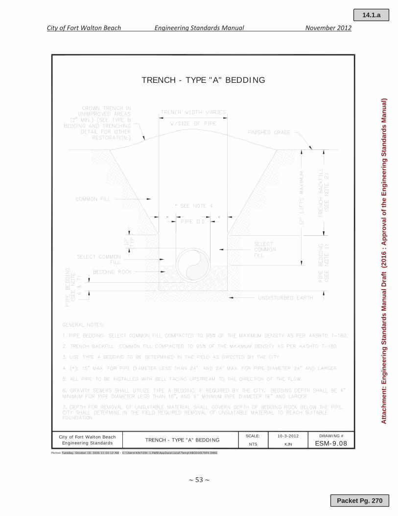
City of Fort Walton Beach TRENCH - TYPE "A" BEDDING10-3-2012 DRAWING #
ESM-9.08SCALE:
KJN
TRENCH - TYPE "A" BEDDING
Plotted Tuesday, October 18, 2005 11:03:12 AM - C:\Users\KNITZM~1.FWB\AppData\Local\Temp\A$C044578F4.DWG
NTSEngineering Standards
14.1.a
Packet Pg. 270
Atta
chm
ent:
Engi
neer
ing
Stan
dard
s M
anua
l Dra
ft (2
016
: App
rova
l of t
he E
ngin
eerin
g St
anda
rds
Man
ual)

City of Fort Walton Beach Engineering Standards Manual November 2012
City of Fort Walton Beach TRENCH - TYPE "B" BEDDING10-3-2012 DRAWING #
ESM-9.09SCALE:
KJN
TRENCH - TYPE "B" BEDDING
Plotted Tuesday, October 18, 2005 11:03:12 AM - C:\Users\KNITZM~1.FWB\AppData\Local\Temp\A$C7D2F0508.DWG
NTSEngineering Standards
14.1.a
Packet Pg. 271
Atta
chm
ent:
Engi
neer
ing
Stan
dard
s M
anua
l Dra
ft (2
016
: App
rova
l of t
he E
ngin
eerin
g St
anda
rds
Man
ual)

City of Fort Walton Beach Engineering Standards Manual November 2012
City of Fort Walton Beach STANDARD THRUST BLOCK10-3-2012 DRAWING #
ESM-9.10SCALE:
KJN
STANDARD THRUST BLOCK
Plotted Tuesday, October 18, 2005 11:03:12 AM - C:\Users\KNITZM~1.FWB\AppData\Local\Temp\A$C73D05CB2.DWG
NTSEngineering Standards
14.1.a
Packet Pg. 272
Atta
chm
ent:
Engi
neer
ing
Stan
dard
s M
anua
l Dra
ft (2
016
: App
rova
l of t
he E
ngin
eerin
g St
anda
rds
Man
ual)
City of Fort Walton Beach Engineering Standards Manual November 2012
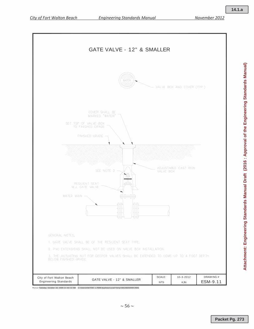
City of Fort Walton Beach GATE VALVE - 12" & SMALLER10-3-2012 DRAWING #
ESM-9.11SCALE:
KJN
GATE VALVE - 12" & SMALLER
Plotted Tuesday, October 18, 2005 11:03:12 AM - C:\Users\KNITZM~1.FWB\AppData\Local\Temp\A$C2E693DE9.DWG
NTSEngineering Standards
14.1.a
Packet Pg. 273
Atta
chm
ent:
Engi
neer
ing
Stan
dard
s M
anua
l Dra
ft (2
016
: App
rova
l of t
he E
ngin
eerin
g St
anda
rds
Man
ual)
City of Fort Walton Beach Engineering Standards Manual November 2012
City of Fort Walton Beach STANDARD FIRE HYDRANT10-3-2012 DRAWING #
ESM-9.12SCALE:
KJN
STANDARD FIRE HYDRANT
Plotted Tuesday, October 18, 2005 11:03:12 AM - C:\Users\KNITZM~1.FWB\AppData\Local\Temp\A$C0E5B6AA6.DWG
NTSEngineering Standards
14.1.a
Packet Pg. 274
Atta
chm
ent:
Engi
neer
ing
Stan
dard
s M
anua
l Dra
ft (2
016
: App
rova
l of t
he E
ngin
eerin
g St
anda
rds
Man
ual)

City of Fort Walton Beach Engineering Standards Manual November 2012
Plotted Tuesday, October 18, 2005 11:03:12 AM - C:\Users\KNITZM~1.FWB\AppData\Local\Temp\A$C46AA39D0.DWG
City of Fort Walton Beach 10-3-2012 DRAWING #
ESM-9.13SCALE:
KJNNTSEngineering Standards
3/4" - 2" WATER METER INSTALLATION
3/4" - 2" WATER METER INSTALLATION
14.1.a
Packet Pg. 275
Attachment: Engineering Standards Manual Draft (2016 : Approval of the Engineering Standards Manual)
City of Fort Walton Beach Engineering Standards Manual November 2012
Plotted Tuesday, October 18, 2005 11:03:12 AM - C:\Users\KNITZM~1.FWB\AppData\Local\Temp\A$C633D0F64.DWG
City of Fort Walton Beach 10-3-2012 DRAWING #
ESM-9.14SCALE:
KJNNTSEngineering Standards
4" & LARGER WATER METER INSTALLATION
4" & LARGER WATER METER INSTALLATION
14.1.a
Packet Pg. 276
Attachment: Engineering Standards Manual Draft (2016 : Approval of the Engineering Standards Manual)
City of Fort Walton Beach Engineering Standards Manual November 2012
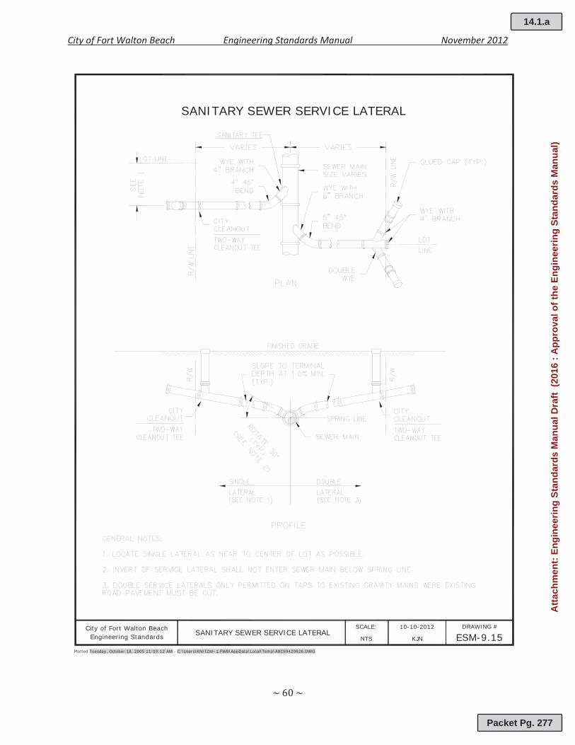
City of Fort Walton Beach SANITARY SEWER SERVICE LATERAL 10-10-2012 DRAWING #
ESM-9.15SCALE:
KJN
SANITARY SEWER SERVICE LATERAL
Plotted Tuesday, October 18, 2005 11:03:12 AM - C:\Users\KNITZM~1.FWB\AppData\Local\Temp\A$C59420626.DWG
NTSEngineering Standards
14.1.a
Packet Pg. 277
Atta
chm
ent:
Engi
neer
ing
Stan
dard
s M
anua
l Dra
ft (2
016
: App
rova
l of t
he E
ngin
eerin
g St
anda
rds
Man
ual)
City of Fort Walton Beach Engineering Standards Manual November 2012
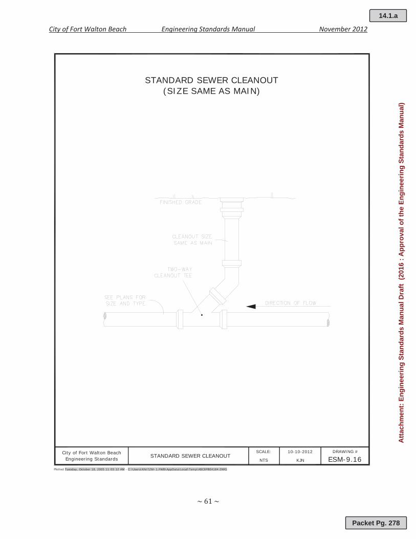
City of Fort Walton Beach STANDARD SEWER CLEANOUT10-10-2012 DRAWING #
ESM-9.16SCALE:
KJN
STANDARD SEWER CLEANOUT(SIZE SAME AS MAIN)
Plotted Tuesday, October 18, 2005 11:03:12 AM - C:\Users\KNITZM~1.FWB\AppData\Local\Temp\A$C6FBE4184.DWG
NTSEngineering Standards
14.1.a
Packet Pg. 278
Atta
chm
ent:
Engi
neer
ing
Stan
dard
s M
anua
l Dra
ft (2
016
: App
rova
l of t
he E
ngin
eerin
g St
anda
rds
Man
ual)
City of Fort Walton Beach Engineering Standards Manual November 2012
City of Fort Walton Beach STANDARD SEWER MANHOLE 10-10-2012 DRAWING #
ESM-9.17SCALE:
KJN
STANDARD SEWER MANHOLE
Plotted Tuesday, October 18, 2005 11:03:12 AM - C:\Users\KNITZM~1.FWB\AppData\Local\Temp\A$C31083A19.DWG
NTSEngineering Standards
14.1.a
Packet Pg. 279
Atta
chm
ent:
Engi
neer
ing
Stan
dard
s M
anua
l Dra
ft (2
016
: App
rova
l of t
he E
ngin
eerin
g St
anda
rds
Man
ual)

City of Fort Walton Beach Engineering Standards Manual November 2012
City of Fort Walton Beach STANDARD SEWER MANHOLE 10-10-2012 DRAWING #
ESM-9.18SCALE:
KJN
STANDARD SEWER MANHOLEWITH DROP CONNECTION
Plotted Tuesday, October 18, 2005 11:03:12 AM - C:\Users\KNITZM~1.FWB\AppData\Local\Temp\A$C36A14484.DWG
NTSEngineering Standards WITH DROP CONNECTION
14.1.a
Packet Pg. 280
Atta
chm
ent:
Engi
neer
ing
Stan
dard
s M
anua
l Dra
ft (2
016
: App
rova
l of t
he E
ngin
eerin
g St
anda
rds
Man
ual)
City of Fort Walton Beach Engineering Standards Manual November 2012
APPENDIX 9A“RESERVED”
14.1.a
Packet Pg. 281
Atta
chm
ent:
Engi
neer
ing
Stan
dard
s M
anua
l Dra
ft (2
016
: App
rova
l of t
he E
ngin
eerin
g St
anda
rds
Man
ual)


