25
1436 Non-inverting Op Amp

1436 Non-inverting Op Amp
Op Amp Amplifier Basics
OThere are two basics forms in
which an Op Amp (Operational
Amplifier) can be used as an
amplifier:
O Inverting configuration
ONon-inverting configuration

741 DIP Pinout Diagram
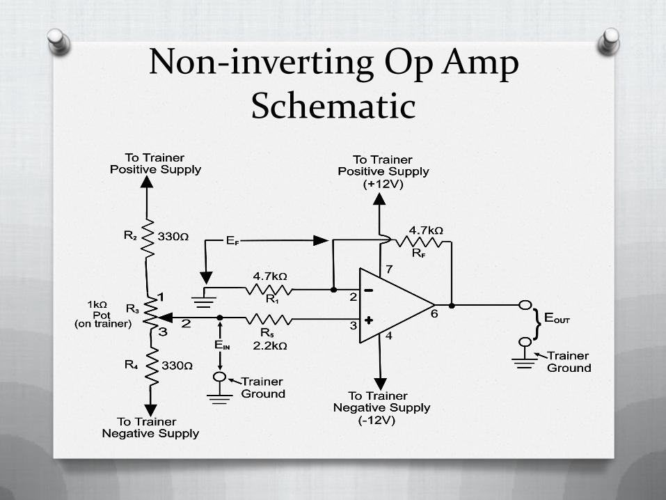
Non-inverting Op Amp Schematic

Practical Considerations for the 741 Non-inverting Op Amp
OThe input bias current is about 80 nA
OThe input offset current is about 10 nA
OThe input impedance is about 2 Meg Ohms
OThe common mode voltage should
be within +/-12V for +/-15V supply
OThe output impedance is about 75
ohms.
OThe voltage gain rolls off 6dB per
octave starting at 100kHz.
OMaximum output Current: 20mA

OThere is a finite input offset which
must be zeroed by a resistor
between pins 1 and 5. The input
offset is typically 2mV to <6mV.
OThe slew rate is 0.5V/microsecond.
O There is some temperature
dependence
OPositive input voltages yield positive
output voltages
ONegative input voltages yield
negative output voltages
OThus, the non-inverting amplifier
does not invert the phase of the
input signal
OThe feedback voltage will have the
same polarity and amplitude
O The voltage between the two input
terminals of a normally operating Op
Amp is always zero volts.
O The maximum output-voltage swing of
an Op Amp should ideally be equal to
the value of the applied voltage.
O The actual maximum output swing of
the 741 Op Amp is actually a little less
than the theoretical maximum.
(Applied Voltage)
O The op amp will no longer operate
linearly if you try to exceed this value
OThe accuracy of the circuits to meet
the calculated values is dependent
on the actual values of the
components used. (Values with their
tolerances)
ORemember resistors have a
tolerance.
O The calculated gain of the amplifier
will very likely be different than the
measured gain.
OThis is true for capacitors and pretty
much any component manufactured
by man.
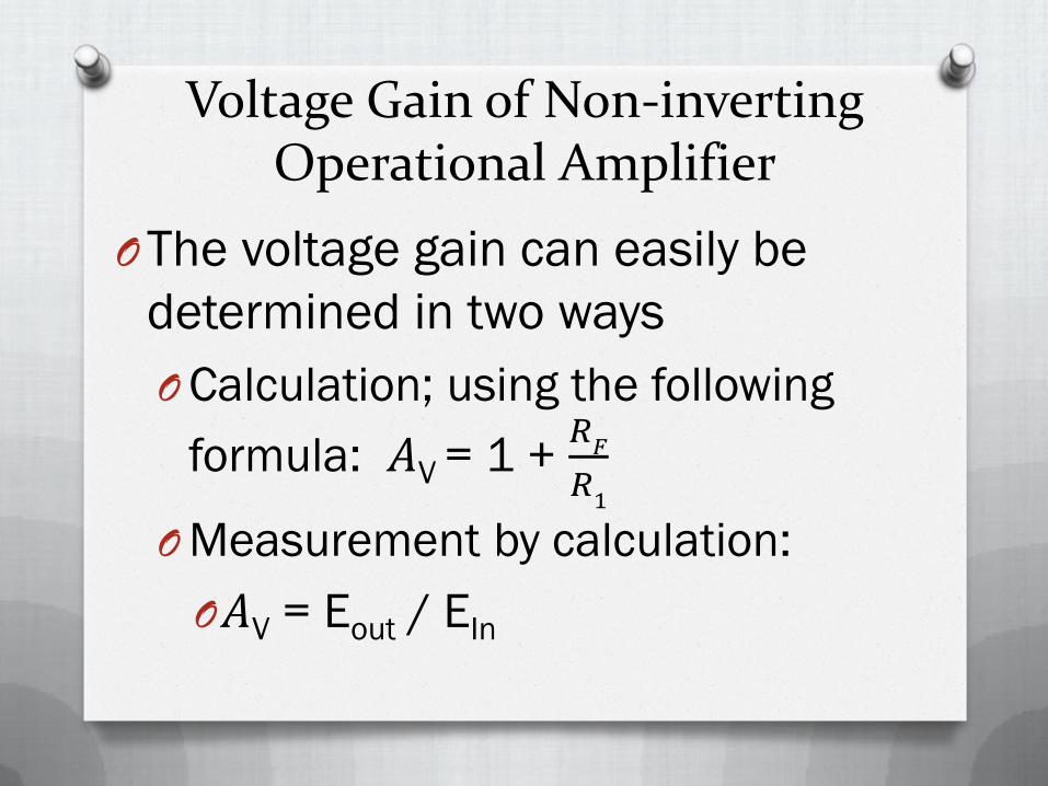
Voltage Gain of Non-inverting Operational Amplifier
OThe voltage gain can easily be
determined in two ways
OCalculation; using the following
formula: 𝐴V = 1 + 𝑅𝐹
𝑅1
OMeasurement by calculation:
O𝐴V = Eout / EIn

Non-inverting Op Amp Schematic
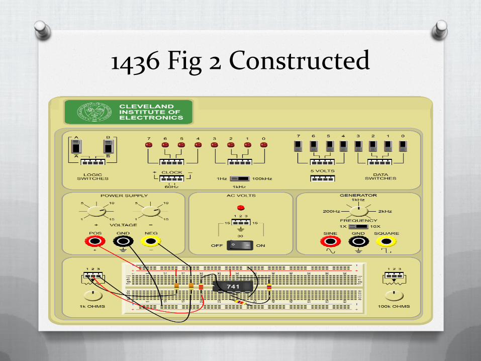
1436 Fig 2 Constructed
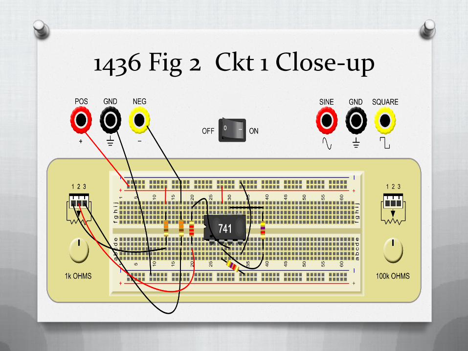
1436 Fig 2 Ckt 1 Close-up
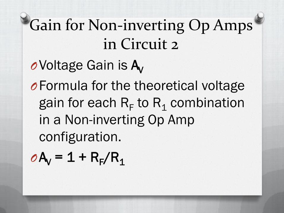
Gain for Non-inverting Op Amps in Circuit 2
OVoltage Gain is AV
OFormula for the theoretical voltage
gain for each RF to R1 combination
in a Non-inverting Op Amp
configuration.
OAV = 1 + RF/R1
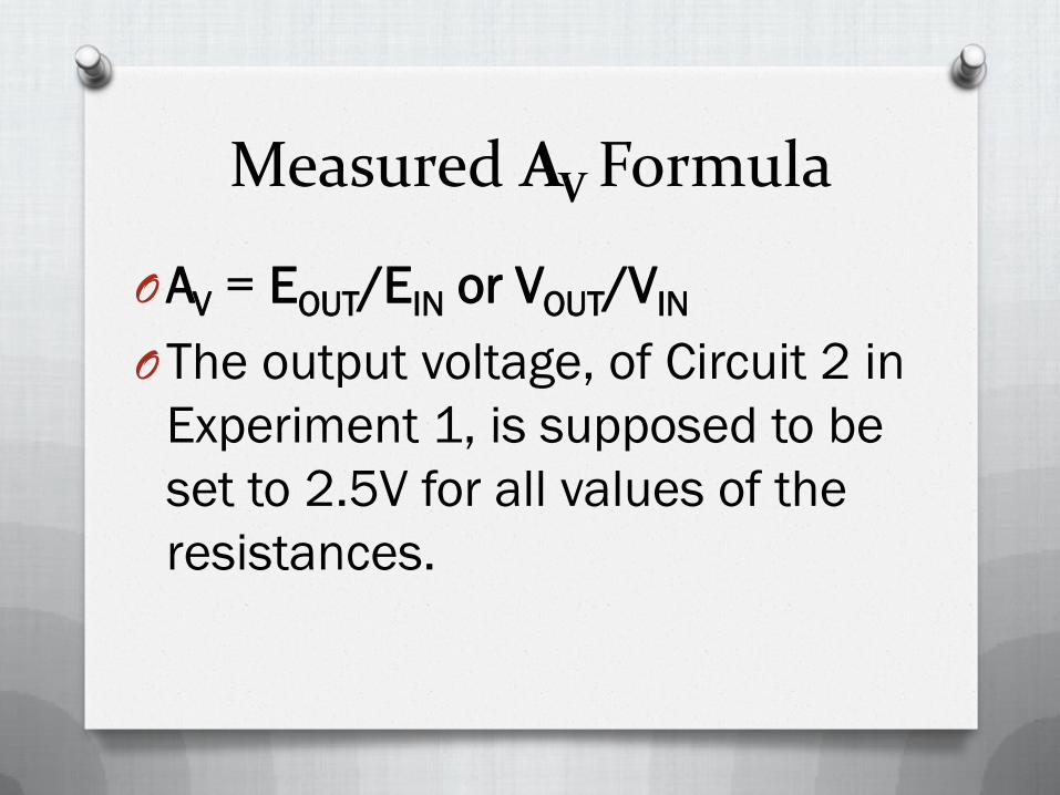
Measured AV Formula
OAV = EOUT/EIN or VOUT/VIN
OThe output voltage, of Circuit 2 in
Experiment 1, is supposed to be
set to 2.5V for all values of the
resistances.

Additional Discussion
ORemember: the theoretical and
measured Voltage Gains can vary
as much as 20% due to the
resistor tolerances.
O It is not unusual to see gains
from 1 to approximately 11 with
the values of resistances used.

Schematic for circuit 2 Exp. 1
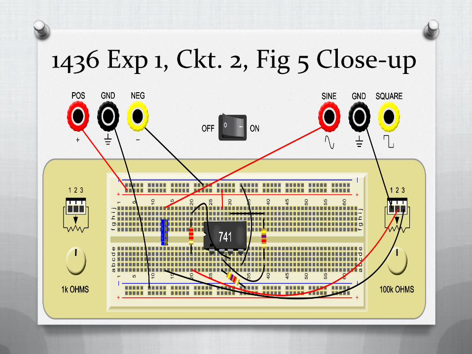
1436 Exp 1, Ckt. 2, Fig 5 Close-up
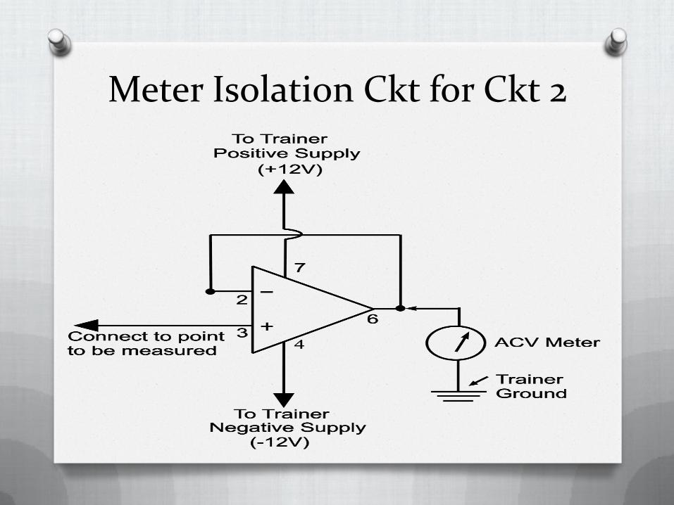
Meter Isolation Ckt for Ckt 2

QUESTIONS?
Resources
O Lesurf, J. (n.d.). Unpublished raw data, University of St. Andrews, St. Andrews, Scotland. Retrieved from http://www.st-andrews.ac.uk/~www_pa/Scots_Guide/datasheets/Opamps/741.html
O Nave, R. (n.d.). The 741: Practical considerations. Retrieved from http://hyperphysics.phy-astr.gsu.edu/hbase/electronic/a741p.html
O Rosenow. (2001). Lesson 1436:
Operational amplifier characteristics.
Cleveland: Cleveland Institute of
Electronics.

The End
Developed and Produced by the Instructors in the CIE Instruction Department.
© Copyright 01/2012
All Rights Reserved / Jan. 2012


