26
1436 Voltage Follower Op Amp Cleveland Institute of Electronics Lesson 1436 Request a course catalog

1436 Voltage Follower Op Amp
Cleveland Institute of Electronics Lesson 1436 Request a course catalog
Op Amp Amplifier Basics
OThere are two basics forms in
which an Op Amp (Operational
Amplifier) can be used as an
amplifier:
O Inverting configuration
ONon-inverting configuration
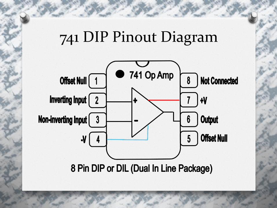
741 DIP Pinout Diagram

Voltage Follower Op Amp Schematic

Practical Considerations for the 741Voltage Follower Op Amp
O The input signal is applied to the
non-inverting input
OBecause of this, the output signal is
not inverted or in phase with the
input

O Inverting input is connected to the
output pin of the Op Amp
OOne assumption is the RF is zero Ω
OR1 is shown to be of infinite
resistance
OThis amplifier has unity gain and
does not invert the phase of the
input signal

OUnity gain means the gain is 1
O This also means you have a 1:1
ratio from the output to the input
O This also means what you put into
the Op Amp is what you get out
OAV = 1 + RF/R1
OAV = 1 + 0/∞ = 1

Practical Considerations for the 741 Operational Amplifier
OThe input bias current is about 80 nA
OThe input offset current is about 10 nA
OThe input impedance is about 2 Meg Ohms

OThe common mode voltage should
be within +/-12V for +/-15V supply
OThe output impedance is about 75
ohms.
OThe voltage gain rolls off 6dB per
octave starting at 100kHz.
OMaximum output Current: 20mA
OThere is a finite input offset which
must be zeroed by a resistor
between pins 1 and 5. The input
offset is typically 2mV to <6mV.
OThe slew rate is 0.3V to 0.5V/
microsecond.
O There is some temperature
dependence

O The voltage between the two input
terminals of a normally operating Op
Amp is always zero volts.
O The maximum output-voltage swing of
an Op Amp should ideally be equal to
the value of the applied voltage.
O The actual maximum output swing of
the 741 Op Amp is actually a little less
than the theoretical maximum.
(Applied Voltage)

O The op amp will no longer operate
linearly if you try to exceed this value
OThe accuracy of the circuits to meet
the calculated values is dependent
on the actual values of the
components used. (Values with their
tolerances)

ORemember resistors have a
tolerance.
O The calculated gain of the amplifier
will very likely be different than the
measured gain.
OThis is also true for capacitors and
pretty much any component
manufactured by man.
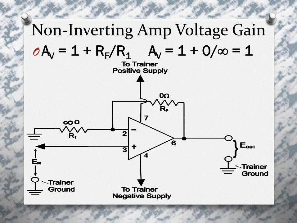
Non-Inverting Amp Voltage Gain OAV = 1 + RF/R1 AV = 1 + 0/∞ = 1

Voltage Follower Voltage Gain OVOUT = VIN EOUT = EIN

Additional Discussion
OThe Voltage Follower provides
impedance matching
O This means this Op Amp provides a
high resistance to a signal source
that would otherwise be severely
loaded down by a low resistance
value.

OAs stated earlier, the output impedance is about 75 Ohms and can drive loads with relatively low resistance values.
OYou will be applying both positive and negative voltages to the following voltage follower circuit.
OYou should see the gain is 1 or unity and no phase inversion take place.
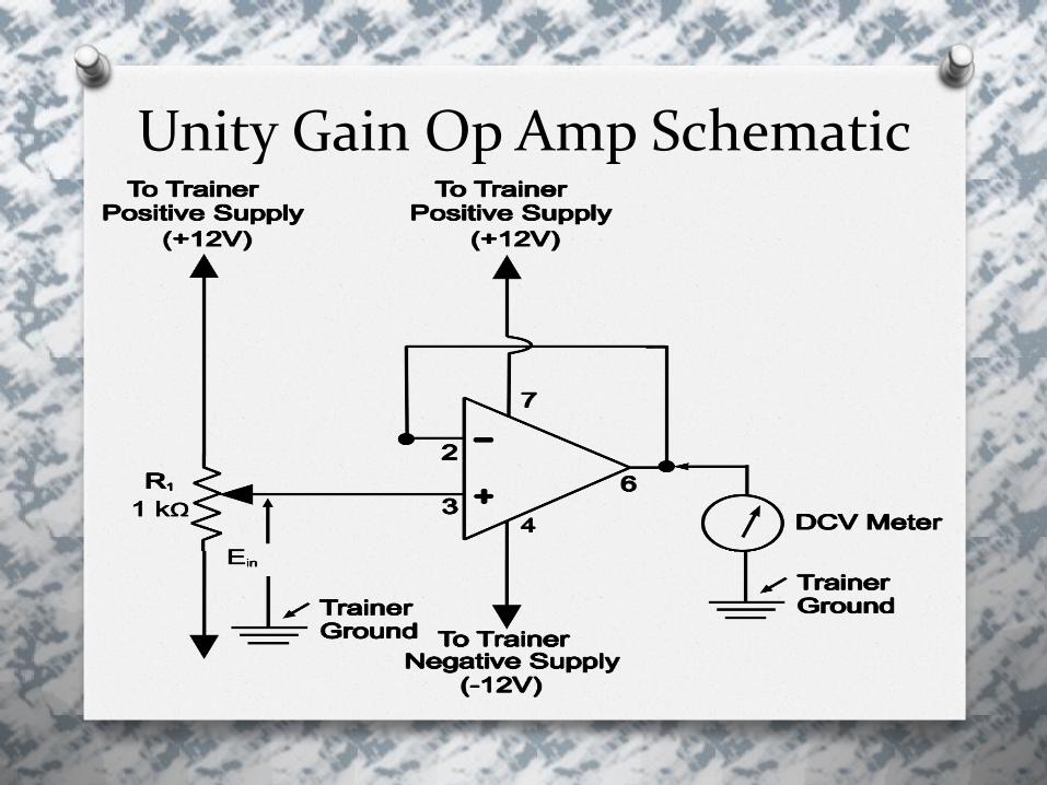
Unity Gain Op Amp Schematic
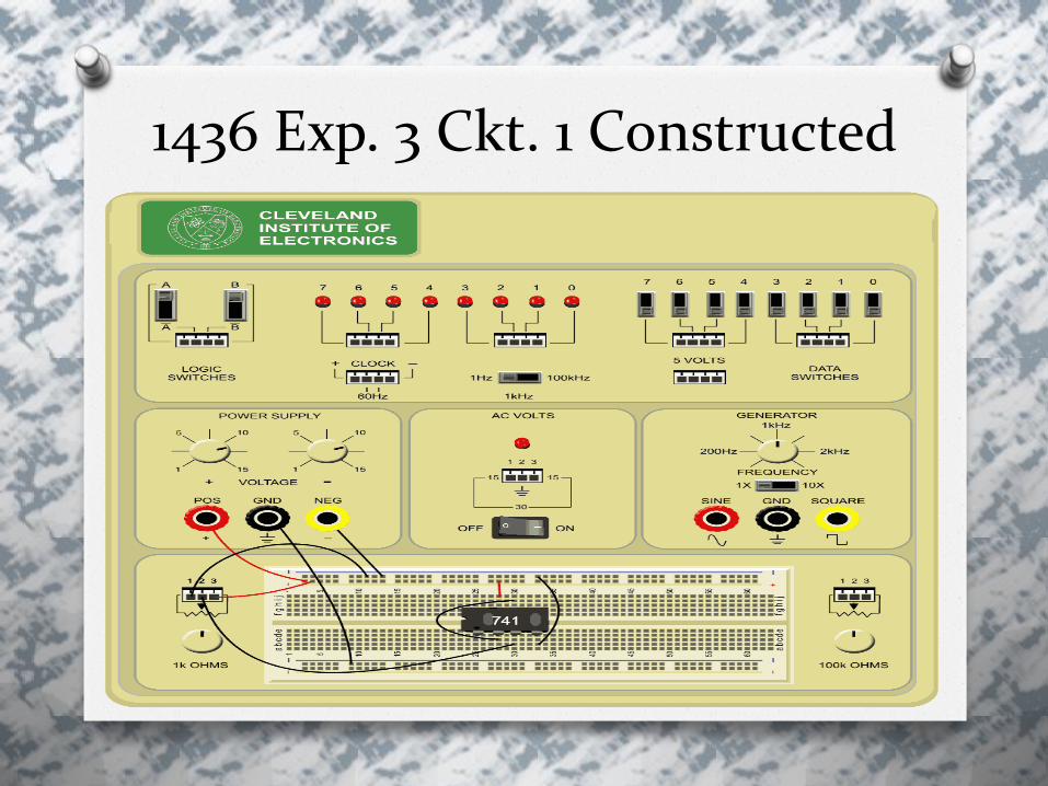
1436 Exp. 3 Ckt. 1 Constructed
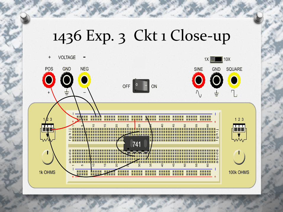
1436 Exp. 3 Ckt 1 Close-up

Schematic for circuit 3 Exp. 2

1436 Exp. 3, Ckt. 2, Close-up

Meter Isolation Ckt for Ckt 2

QUESTIONS?

Resources
O Rosenow. (2001). Lesson 1436:
Operational amplifier characteristics.
Cleveland: Cleveland Institute of
Electronics.

The End
Developed and Produced by the Instructors in the CIE Instruction Department.
© Copyright 01/2012
All Rights Reserved / Jan. 2012


