Robway Crane Safety Systems Pty Ltd Adelaide, South Australia
1450 Manual
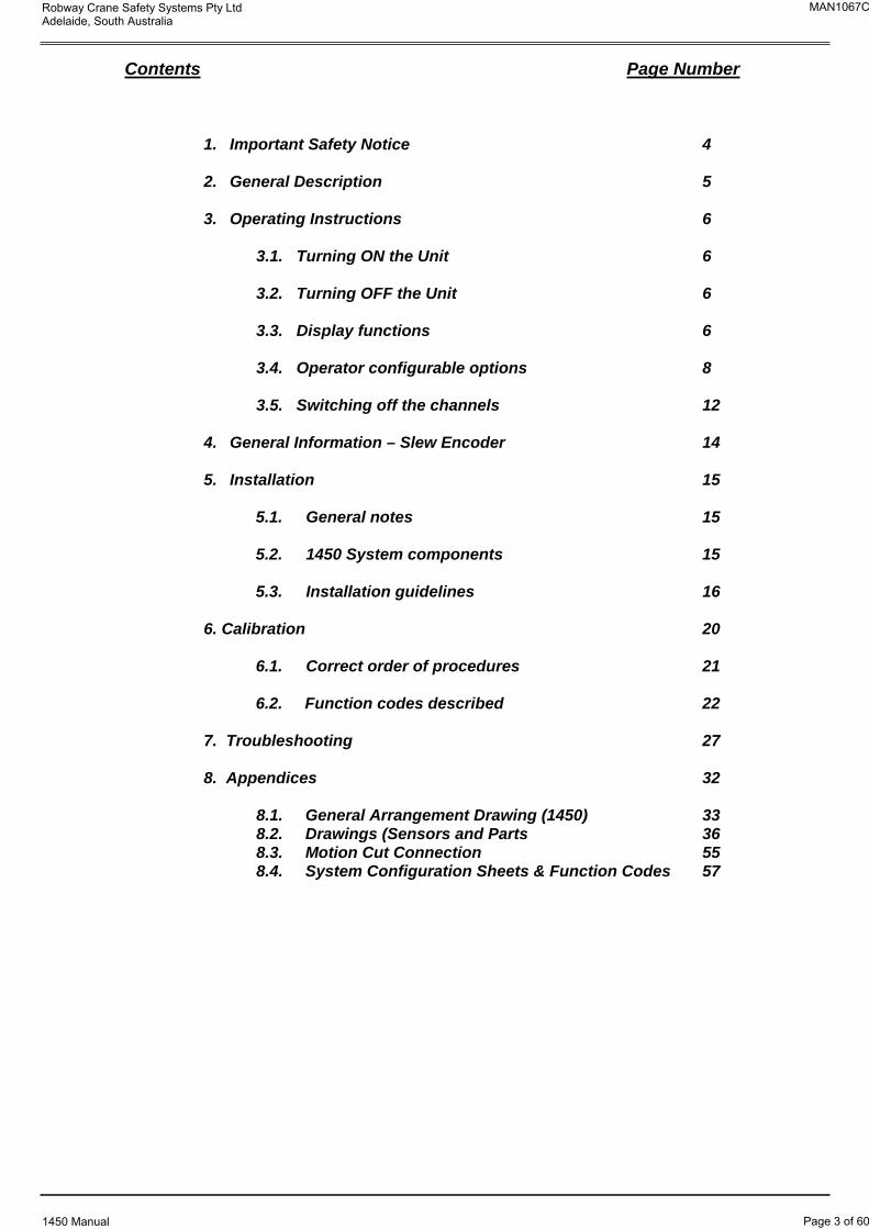
Contents Page Number
1. Important Safety Notice 4
2. General Description 5
3. Operating Instructions 6
3.1. Turning ON the Unit 6
3.2. Turning OFF the Unit 6
3.3. Display functions 6
3.4. Operator configurable options 8
3.5. Switching off the channels 12
4. General Information – Slew Encoder 14
5. Installation 15
5.1. General notes 15
5.2. 1450 System components 15
5.3. Installation guidelines 16
6. Calibration 20
6.1. Correct order of procedures 21
6.2. Function codes described 22
7. Troubleshooting 27
8. Appendices 32
8.1. General Arrangement Drawing (1450) 33 8.2. Drawings (Sensors and Parts 36 8.3. Motion Cut Connection 55 8.4. System Configuration Sheets & Function Codes 57
MAN1067C
Page 3 of 60
Robway Crane Safety Systems Pty Ltd Adelaide, South Australia
1450 Manual
1. Important Safety Notice
The Model 1450 Length / Angle / Radius / Slew Zone and ATB Indication System
is a device that allows the operator to set the low and high (or minimum and
maximum) limits of the length, angle, and radius, and warns the operator of “out
of limits” condition and/or overhoist (two-blocking) condition which could cause
damage to property, crane and personnel.
The system is not a substitute for good operator judgement, experience and safe
crane operation. The operator is solely responsible for the safe operation of the
crane.
The operator must, prior to operation of the crane, read this manual carefully and
thoroughly and shall ensure that all operational instructions and warnings are
understood and complied with.
Proper system operation requires the operator to correctly set the operational
limits and parameters of the System to match the crane setup and working
configuration.
The system is equipped with a Cancel/Mute-Alarm button on the panel which
bypasses alarms and motion cut function (if crane motion cut controls are
installed) at which time the system can no longer warn of “out of limits”
condition and/or overshoist condition and must only be operated strictly in
accordance to the crane manufacturer’s setup and operation procedures. The
operator shall be solely responsible for the use and operation of this button.
MAN1067C
Page 4 of 60
Robway Crane Safety Systems Pty Ltd Adelaide, South Australia
1450 Manual
2. General Description
The Model 1450 is a member of the ROBWAY 1400 Series Indication Systems and
is specifically designed for low-cost applications.
Please note that the 1450 is NOT a safe load indicator.
It does not contain any load charts and therefore cannot warn of approaching
overloads.
The 1450 is a microprocessor-controlled Length, Angle, Radius, Slew Zone and ATB indicator.
It is suitable for most low-cost applications for strut (lattice) boom or telescopic cranes with or without fly-jibs.
The 1450 is fully configurable on site and requires very little installation time and operator training.
Although not a safe load indicator, the 1450 can be configured to give warning and motion cut on Two-Blocking and on reaching operator settable Length / Angle / Radius / Slew Zone limits. These limits stay in effect until changed or cancelled by the operator. They are remembered even after the 1450 has been switched off (with the exception of Slew Zone limits).
These limits can be very convenient for radius spotting or as a reminder not to go outside certain operating regions. The 1450 activates both visual and audible alarms if these limits are reached or passed. Optionally, the 1450 can activate motion cut if this option is turned on. Please see Section 6. “Calibration” for details.
MAN1067C
Page 5 of 60
Robway Crane Safety Systems Pty Ltd Adelaide, South Australia
1450 Manual
3. Operating Instructions
The following sections explain how to operate the 1450 System and make best use of its capabilities.
3.1. Turning ON the Unit
Power to the unit is from the crane battery through the start-up or ignition key. In some applications an additional switch may be used to enable the operator to switch the unit on/off as required.
As soon as power is applied to the unit, its display and other indicators should light up and the unit should go through its self-test operation.
3.2. Turning OFF the Unit
The unit will stop working as soon as the power is removed from it by switching off any of the switches indicated in Section 3.1 above.
3.3. Display Functions
The display window functions are selected by the SELECT push button. The current function is indicated by the lamp next to its label being switched ON. The initial function of this window is set to displaying RADIUS.
Other functions can be selected by pressing the SELECT key once to activate
the next function, or by pressing and holding the SELECT key to step through the functions in turn. The functions for the display window are as follows:
LENGTH
When the LENGTH display is selected, using the SELECT button, the display window shows the current length value. This length value indicates the current main boom length when the MAIN indicator is ON and it shows the main boom plus the fly jib length when the FLY indicator is ON.
Please note, that the main boom length will only be changing if the 1450 isconfigured for telescopic crane application and it will be showing a fixed value if the 1450 is configured for a strut boom crane application.
Note:To configure system for STRUT BOOM crane application, switch OFF the Length Channel in function code F-05 or F-06. Please refer to Section 3.5. “Switching Off the Channels”, Section 6.26. “View Uncalibrated Boom Length Input”, and Section 6.27. “View Calibrated Boom Length Input” for details and instructions.
The fly jib length, added to the main boom length when the fly is selected, can be varied. Please refer to Section 3.4.4. “Changing Fly Jib Length” for setting required fly jib length.
MAN1067C
Page 6 of 60
Robway Crane Safety Systems Pty Ltd Adelaide, South Australia
1450 Manual
ANGLE
When the ANGLE display is selected, using the SELECT button, the display window shows the current angle value. This angle value indicates the main boom angle regardless of whether MAIN or FLY is selected.
Please note, that the main boom angle is automatically read by the 1450 froman angle sensor (which is mounted on the side of the main boom during installation time). The fly jib offset angle is set by the operator. Please refer to Section 3.4.5. “Changing Fly Jib Offset Angle” for setting required fly jib offset angle.
RADIUS
Radius is the horizontal distance (the distance measured on the ground) from the centre line of rotation to the centre of the load.
When the RADIUS display is selected, using the SELECT button, the display window shows the current radius value. This radius value indicates the radius of the main boom when the MAIN indicator is ON and it indicates the radius of the fly jib when the FLY indicator is ON.
Note:For telescopic cranes, functions to correct for boom deflection have been implemented on the 1450. Please refer to Section 6. “Calibration” for details.
LIMIT
The limit indicator cannot be selected. This indicator comes on automatically when the operator presses the LIMIT button to view or change the limit settings for length, angle or radius, or it comes on in conjunction with one of the Length / Angle / Radius indicators to indicate a specific limit has been reached, i.e.:
The radius indicator and the limit indicator blinking means that a radius limit has been exceeded. The length indicator and the limit indicator blinking means that a length limit has been exceeded. The angle indicator and the limit indicator blinking means that an angle limit has been exceeded. The limit indicator blinking alone means that a slew zone limit has been exceeded.
CANCEL
Should any “out of limits” condition and/or overhoist condition occur and alarms/motion cut activate, the operator can disable these by pressing the CANCEL button. As a reminder of alarm/motion cut over-ride, the 1450 will have its O/RIDE and ALARM indicators ON.
The CANCEL button should only be used if it is absolutely necessary and must be de-activated as soon as possible. If the CANCEL button is not de-activated after use, you may not be able to see any other “out of limits” conditions.TEST
This button starts up a self-test procedure. When activated the 1450 will check its input channels, show test patterns in the display window so that the operator can check the operation of the display. The 1450 will also activate the
MAN1067C
Page 7 of 60
Robway Crane Safety Systems Pty Ltd Adelaide, South Australia
1450 Manual
audible/visual alarms and the motion cut relay if connected. We recommend that this button be pressed periodically. If there is any error/s the 1450 will
display an ERROR CODE (refer to Section 7. “Troubleshooting” for details).
ATB Indicator (Red LED)
If the optional Anti-Two-Block switch is installed, this indicator will be activated when a Two-Blocking condition is detected and will be lit until this condition is removed. Please note that motion cut will not be activated if the O/RIDE lamp is ON (refer to CANCEL button on previous page).
If this lamp or LED is ON when the optional switch is NOT installed then the Anti-Two-Block inputs are left open incorrectly. Ensure that the “ATB” bullet type connectors of the power cable are shorted together.
3.4. Operator Configurable Options
The 1450 is fully configurable on site by the operator. This allows the operator to change the boom length, fly jib length and jib offset angle whenever the
crane is re-configured.
Please note however, if these options are not accurately set, the 1450 will also be inaccurate
There are some variables that are not altered in calibration mode but rather in normal mode. Viewing and changing these parameters is done by use of the
“User-Menu.”
This menu can be displayed any time during normal operation by pressing and holding the UP or DOWN arrow keys on the top right of the display for approximately two seconds.
When the menu is entered the display will show one of five prompts (in special cases the menu may be limited to less than five).
- LS - (action)
- rS - (action)
- JL - (value)
- JA - (value)
- BL - (value)
These prompts indicate the settings for Left Side Limit, Right Side Limit, Jib
Length, Jib Angle and Boom Length respectively. The UP / DOWN arrow keys can be used to cycle through them. Pressing the ENTER key at any of these prompts will allow the indicated value to be altered or action to be performed. Pressing the CANCEL key will exit the User-Menu and return the 1450 to normal operation.
NOTE:When the User-Menu is displayed, the 1450 is effectively in an Over-Ride condition and thus limits and motion cuts do not occur. This is indicated to the operator by the O/Ride LED illuminating and a short audible beep sounding every 5 seconds.
MAN1067C
Page 8 of 60
Robway Crane Safety Systems Pty Ltd Adelaide, South Australia
1450 Manual
3.4.1. Setting Left-Side Slew Zone Limit
This function requires the intallation of the Robway Slew Encoder. Please see Section 4. “General Information - Slew Encoder” for details.
Setting the Left-Side Slew Zone Limit is done by using the User Menu.
Enter the User Menu (by pressing the UP or DOWN arrow) and cycle through the menu until “-LS-” is displayed.
Slew the boom to the left-most position of the safe zone. Press ENTER. The message “LEFT SIDE SET” will be displayed briefly on the LCD screen. From now on the alarm and the motion cut will occur when the boom reaches this position while rotating to the left.
3.4.2. Setting Right-Side Slew Zone Limit
This function requires the intallation of the Robway Slew Encoder. Please see Section 4. “General Information - Slew Encoder” for details.
Setting the Right-Side Slew Zone Limit is done by using the User Menu.
Enter the User Menu (by pressing the UP or DOWN arrow) and cycle through the menu until “-rS-” is displayed.
Slew the boom to the right-most position of the safe zone. Press ENTER. The message “RGHT SIDE SET” will be displayed briefly on the LCD screen. From now on the alarm and the motion cut will occur when the boom reaches this position while rotating to the right.
3.4.3. Changing Main Boom Length
Changing main boom length is only allowed if the 1450 is configured for strut boom operation.
Note:To configure system for STRUT BOOM crane application, switch OFF the Length Channel in function code F-05 or F-06. Please refer to Section 3.5. “Switching Off the Channels”, Section 6.26. “View Uncalibrated Boom Length Input”, and Section 6.27. “View Calibrated Boom Length Input” for details and instructions.
Changing the Main Boom length (as well as Jib Length and Jib angle) is done by using the User Menu.
Enter the User Menu (by pressing the UP or DOWN arrow) and cycle through the menu until “-BL-” is displayed.
Hit ENTER to display the current setting for the Boom Length on the screen. If this value does not need to be varied, press the CANCEL key to return to the menu prompt. If the length is not correct, use the UP and DOWN arrows to alter the number displayed in the window. Once the correct Boom Length is displayed, press the ENTER key to store this value or press the CANCEL key to ignore the new value and retain the previous setting.
3.4.4. Changing Fly Jib Length
MAN1067C
Page 9 of 60
Robway Crane Safety Systems Pty Ltd Adelaide, South Australia
1450 Manual
To change the Fly Jib length, press the UP or DOWN button until the User Menu prompt is displayed.
Press the UP/DOWN keys until the prompt for setting the Jib Length is displayed (“-JL-”).
Press ENTER to display the current setting for the Jib Length. Use the UP and DOWN keys to alter this value as required and press the ENTER key to store the displayed value, or press the CANCEL key to ignore the displayed value’ and retain the previous setting. In either case, the display will return to showing the menu prompts. Press CANCEL to exit the User Menu.
3.4.5. Changing Fly Jib Offset Angle
To change the Fly Jib Angle, press the UP or DOWN button until the User Menu prompt is displayed.
Press the UP/DOWN keys until the prompt for setting the Jib Angle is displayed (“-JA-”).
Press ENTER to display the current setting for the Jib Angle. Use the UP and DOWN keys to alter this value as required and press the ENTER key to store the displayed value, or press the CANCEL key to ignore the displayed value and retain the previous setting. In either case, the display will return to showing the menu prompts. Press CANCEL to exit the User Menu.
3.4.6. Setting Low/High Limits On Length
Setting limits on boom length when operating in strut boom mode is allowed. The limits in this case will restrict the User from operating on a boom length which is outside of the length limits.
Note:To configure system for STRUT BOOM crane application, switch OFF the Length Channel in function code F-05 or F-06. Please refer to Section 3.5. “Switching Off the Channels”, Section 6.26. “View Uncalibrated Boom Length Input”, and Section 6.27. “View Calibrated Boom Length Input” for details and instructions.
To set limits on the main boom length, press the SELECT button until the LENGTH indicator comes ON.
If you want the limits to be activated while working over the main boom sheave, make sure that the MAIN indicator is ON,. If you want the limits to be active while working over the FLY sheave then make sure that the FLY indicator is ON. Use the MAIN button to change from MAIN to FLY or FLY to MAIN.
If you want to set a low limit for the main boom length then retract the main boom to the length where you want the alarm to go off. Then press and hold the LIMIT/ENTER button and press the DOWN arrow button.
If you want to set a high limit for the main boom length then extend the main boom to the length where you want the alarm to go off. Then press and hold the LIMIT/ENTER button and press the UP arrow button.
If it is not possible or advisable to drive the crane to the desired limit, then it is
MAN1067C
Page 10 of 60
Robway Crane Safety Systems Pty Ltd Adelaide, South Australia
1450 Manual
possible to alter the limit setting by hand. Follow the procedure outlined above for setting the limit, however, when the UP or DOWN arrow is pressed to select the limit as a low or high limit, DON’T release the LIMIT/ENTER button.
While still pressing the LIMIT/ENTER button, the UP and DOWN keys can be used to alter the value for the limit which is going to be set. Once the value displayed shows the limit desired, release the LIMIT/ENTER key to store the new limit.
Note that you may have both LOW and HIGH limit set for LENGTH The alarms will go off if any one of the limits is reached.
3.4.7. Setting Low/High Limits On Angle
To set limits on the main boom angle, press the SELECT button until the ANGLE indicator comes ON.
If you want the limits to be activated while working over the main boom sheave, make sure that the MAIN indicator is ON,. If you want the limits to be active while working over the FLY sheave then make sure that the FLY indicator is ON Use the MAIN button to change from MAIN to FLY orFLYto MAIN
If you want to set a low limit for the main boom angle then luff down to the main boom angle where you want the alarm to go off. Then press and hold the LIMIT/ENTER button and press the DOWN arrow button.
If you want to set a high limit for the main boom angle then luff up to the main boom angle where you want the alarm to go off. Then press and hold the LIMIT/ENTER button and press the UP arrow button.
If it is not possible or advisable to drive the crane to the desired limit, then it is possible to alter the limit setting by hand. Follow the procedure outlined above for setting the limit, however, when the UP or DOWN arrow is pressed to select the limit as a low or high limit, DON’T release the LIMIT/ENTER button.
While still pressing the LIMIT/ENTER button, the UP and DOWN keys can be used to alter the value for the limit which is going to be set. Once the value displayed shows the limit desired, release the LIMIT/ENTER key to store the new limit.
Note that you may have both LOW and HIGH limit set for ANGLE. The alarms will go off if any one of the limits is reached.
3.4.8. Setting Low/High Limits On Radius
To set limits on the radius, press the SELECT button until the RADIUS indicator comes ON.
If you want the limits to be activated while working over the main boom sheave, make sure that the MAIN indicator is ON,. Ifyou want the limits to be active while working over the FLY sheave then make sure that the FLY indicator is ON Use the MAIN button to change from MAIN to FLY orFLYto MAIN
If you want to set a low limit for the radius then luff down to the radius value where you want the alarm to go off. Then press and hold the LIMIT/ENTER button and press the DOWN arrow button.
If you want to set a high limit for the radius then luff up to the radius value where you want the alarm to go off. Then press and hold the LIMIT/ENTER
MAN1067C
Page 11 of 60
Robway Crane Safety Systems Pty Ltd Adelaide, South Australia
1450 Manual
button and press the UP arrow button.
If it is not possible or advisable to drive the crane to the desired limit, then it is possible to alter the limit setting by hand. Follow the procedure outlined above for setting the limit, however, when the UP or DOWN arrow is pressed to select the limit as a low or high limit, DON’T release the LIMIT/ENTER button.
While still pressing the LIMIT/ENTER button, the UP and DOWN keys can be used to alter the value for the limit which is going to be set. Once the value displayed shows the limit desired, release the LIMIT/ENTER key to store the new limit.
Note that you may have both LOW and HIGH limit set for RADIUS. The alarms will go off if any one of the limits is reached.
3.4.9. Reviewing Current Limit Settings
To check the limits set for length, angle or radius press the SELECT button until the correct indicator is lit, i.e. LENGTH if you want to check limits for length, etc.
Make sure that the MAIN indicator is ON if you want to check the limits while working over the main boom sheave. If you want to check the limits while working over the FLY sheave then make sure that the FLY indicator is ON Use the MAIN button to change from MAIN to FLY or FLY to MAIN
Now press the LIMIT/ENTER button, the display will show the low and high limits set in turn until the LIMIT/ENTER button is released.
3.4.10. Clearing Current Limit Settings
To clear the limits set for length, angle or radius press the SELECT button until the correct indicator is lit, i.e. LENGTH if you want to check limits for length, etc.
Make sure that the MAIN indicator is ON if you want to check the limits while working over the main boom sheave. If you want to check the limits while working over the FLY sheave then make sure that the FLY indicator is ON. Use the MAIN button to change from MAIN to FLY or FLY to MAIN. Now press and hold the LIMIT/ENTER button then press the CANCEL button as well. This will “clear” the low limit to -90.0 and set the high limit to 100.0, for the selected function.
To clear the limits set for the slew zone set both left- and right-side limits to the same position. Turning off the 1450 system also clears the slew zone limits.
3.5. Switching Off the Channels
The device has been designed in such a way that unused sensors can be individually disabled. This can be done in calibration mode (see Section 6. “Calibration for details).
Respective function codes are:
F-01 or F-02 to switch off/on the angle sensor F-05 or F-06 to switch off/on the length sensor F-09 to switch off/on the slew zone encoder
It is important that unused sensor channels are disabled (switched off) to avoid system failure alarms.
MAN1067C
Page 12 of 60
Robway Crane Safety Systems Pty Ltd Adelaide, South Australia
1450 Manual
MAN1067C
Page 13 of 60
Robway Crane Safety Systems Pty Ltd Adelaide, South Australia
1450 Manual
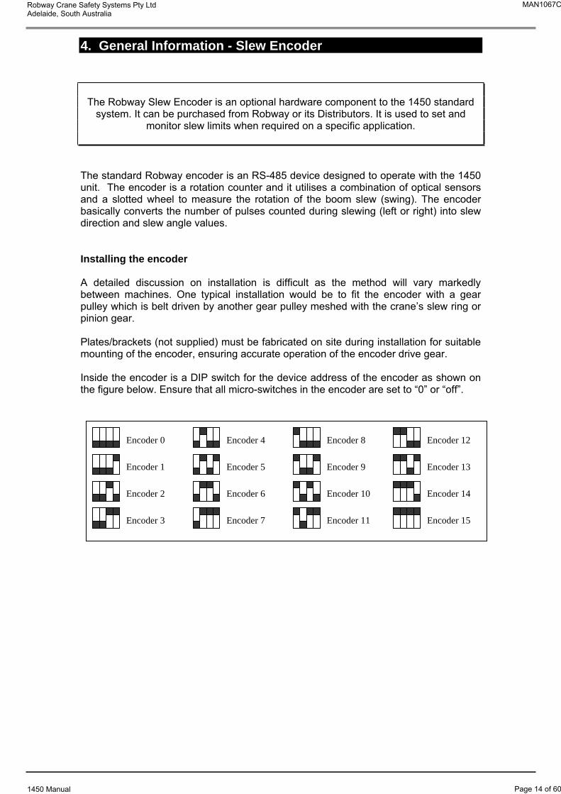
4. General Information - Slew Encoder
The Robway Slew Encoder is an optional hardware component to the 1450 standard system. It can be purchased from Robway or its Distributors. It is used to set and
monitor slew limits when required on a specific application.
The standard Robway encoder is an RS-485 device designed to operate with the 1450 unit. The encoder is a rotation counter and it utilises a combination of optical sensors and a slotted wheel to measure the rotation of the boom slew (swing). The encoder basically converts the number of pulses counted during slewing (left or right) into slew direction and slew angle values.
Installing the encoder
A detailed discussion on installation is difficult as the method will vary markedly between machines. One typical installation would be to fit the encoder with a gear pulley which is belt driven by another gear pulley meshed with the crane’s slew ring or pinion gear.
Plates/brackets (not supplied) must be fabricated on site during installation for suitable mounting of the encoder, ensuring accurate operation of the encoder drive gear.
Inside the encoder is a DIP switch for the device address of the encoder as shown on the figure below. Ensure that all micro-switches in the encoder are set to “0” or “off”.
Encoder 2
Encoder 3
Encoder 4
Encoder 5
Encoder 6
Encoder 7
Encoder 8
Encoder 9
Encoder 10
Encoder 11
Encoder 12
Encoder 13
Encoder 14
Encoder 15
Encoder 1
Encoder 0
MAN1067C
Page 14 of 60
Robway Crane Safety Systems Pty Ltd Adelaide, South Australia
1450 Manual
5. Installation
This part of the manual is intended for technical people who have been trained by ROBWAY or its distributors. It contains all necessary information to install and
commission the ROBWAY 1450 system.
The following sections should be read initially, at least once to understand the general concept of the installation and calibration procedures. Special attention should be paid to Section 6.1 which describes the CORRECT ORDER OF PROCEDURES.
Using the FUNCTION CODE listing at the rear of this manual, the installer should then use those functions to carry out the required operations. For a detailed description of the individual function codes the installer should refer to Section 6.2 FUNCTION CODES DESCRIBED.
5.1. General Notes
In general, each installation will differ from others, which makes a general description of installation almost impossible. For each installation, however, information will be available in the form of diagrams and instructions. This information will be supplied in the manual with the system, and it is this information the installer must refer to. The main purpose of the installation information is to enable the correct wiring of the display, assuming the sensors have been correctly installed. If there are any queries with regard to the installation of the system, the installer should call the authorised ROBWAY distributor from which the system was purchased.
The majority of the information required for installation is contained in the wiring diagrams supplied with the manual. This diagram should contain all of the components used in the system, and their interconnection. Detailed information such as cable/connector type may not be provided unless these are to be sourced by the installer. Information relating to the mounting of the display etc. will also not generally be given as this is often decided on-site once the equipment has been received. Unless specific detail is given, a common sense approach must be taken with all decisions.
5.2. 1450 System Components
The 1450 Display Module,
The computerised display and control systems.
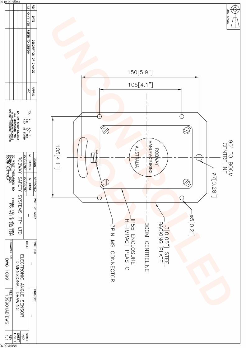
Angle Sensor (STRUT/LATTICE BOOM cranes only),
This is an electronic angle sensor, housed in an IP68 enclosure, used for Strut Boom cranes. The angle sensor is used to send a signal which is proportional to the angle of the boom.
Recoil Drum with Integral Length/Angle Sensor (TELESCOPIC cranes only),
MAN1067C
Page 15 of 60
Robway Crane Safety Systems Pty Ltd Adelaide, South Australia
1450 Manual
For Telescopic cranes, the length and angle sensors are contained in a single Recoil Drum mounted at the side of the boom. The end of the payout cable of the drum is terminated at the boom tip to monitor the boom length as the boom retracts and extends. This payout cable is also used to wire the ATB switch/es when required.
Cabling,
Allows the connection of system components in a convenient manner.
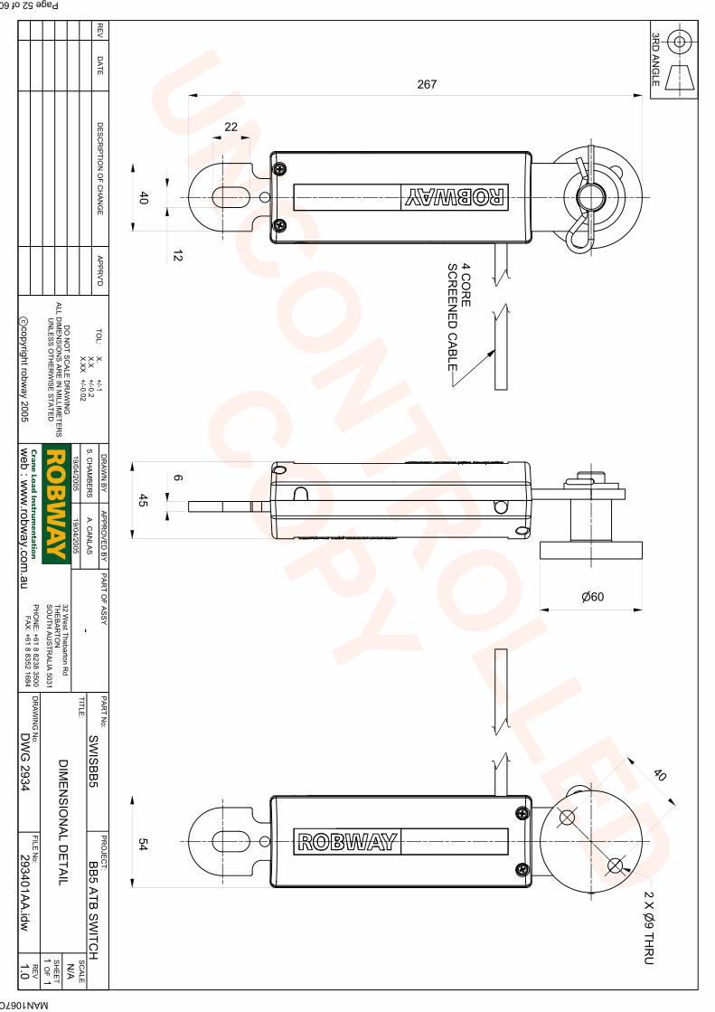
Optional Anti-Two-Block,
This allows the computer to automatically detect and warn of Two-Blocking condition. For installation and use of this system refer to its own, separate manual.
Please note that if the optional Ani-2-Block assembly is not used, you must connect the TWO BULLET connectors, marked as “ATB”, together (i.e. short the wires together), otherwise the 1445/1455 will always sound the alarms and indicate Two-Blocking condition, i.e. the ATB LED indicator on the front panel will be ON.
Optional Slew Encoder,
Used to monitor the relative slew position of the boom. Please see also Section 4. “General Information – Slew Encoder” for details.
5.3. Installation Guidelines
5.3.1. Display Unit
Fit the Display Unit in a convenient position in the crane cabin such that the operator can view the displays and reach the push buttons comfortably.
Standard back plate bracket and kit comprising of bolts and nuts are provided. Special bracket may need to be fabricated on site for suitable mounting in the cabin.
Care must also be taken to ensure that the mounting bracket for the display is earthed onto the chassis of the crane to ensure the display is protected against radio frequency interference.
Fix the angle sensor orientated for right hand side (RHS) of the boom in a convenient position close to the operator's cab by bolting/welding the mounting bracket provided in a vertical plane at 90 degrees to the boom centreline.
It is usual to fit the angle sensor to the 'inside' of the LHS boom butt
section. This position usually provides good mechanical protection.
Ensure the arrow on the enclosure is pointing to the boom tip.
MAN1067C
Page 16 of 60
Robway Crane Safety Systems Pty Ltd Adelaide, South Australia
1450 Manual
Mount/bolt the sensor on the mounting bracket and route the cable carefully around the boom pivot to the cab. Clip the cable to the boom and turret using adequate straps/cable ties provided ensuring that cable is not pinched or stretched as boom moves through its full luffing arc (see also “Cabling – Boom Sensors” item in this Section). Only connect the plug when finished welding.
Please note that high tensile booms require proper welding procedure specifications. Obtain specialist assistance in these cases.
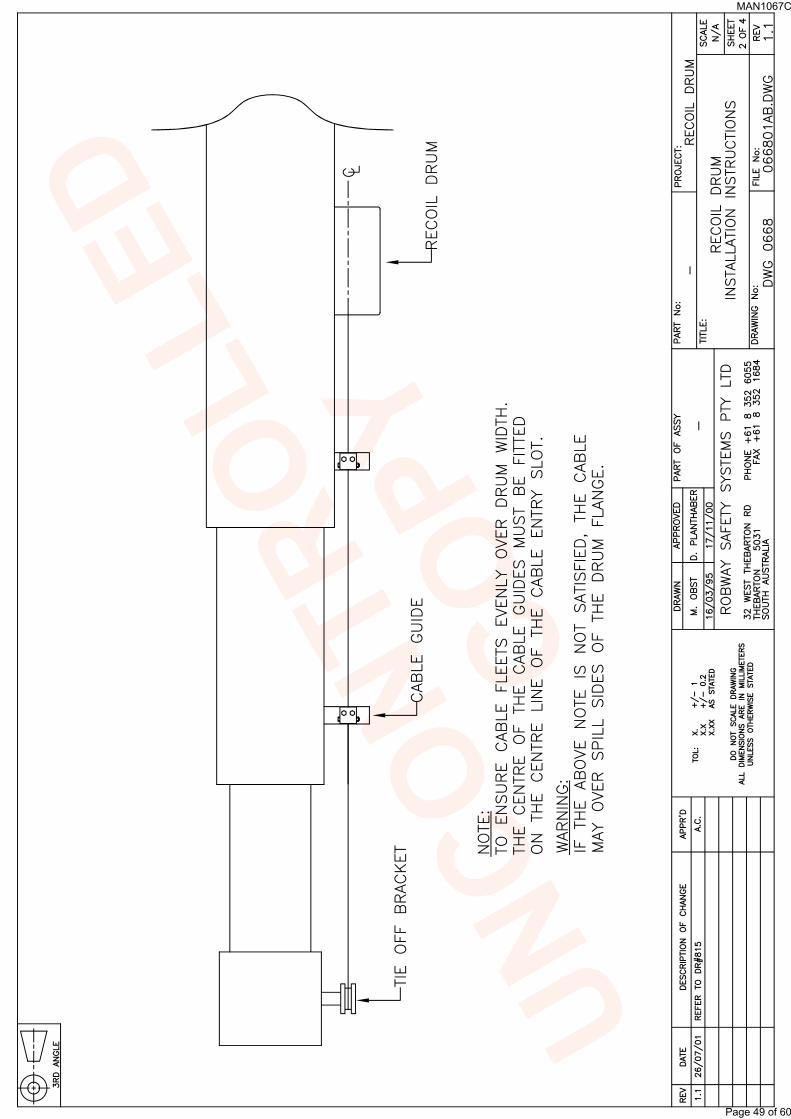
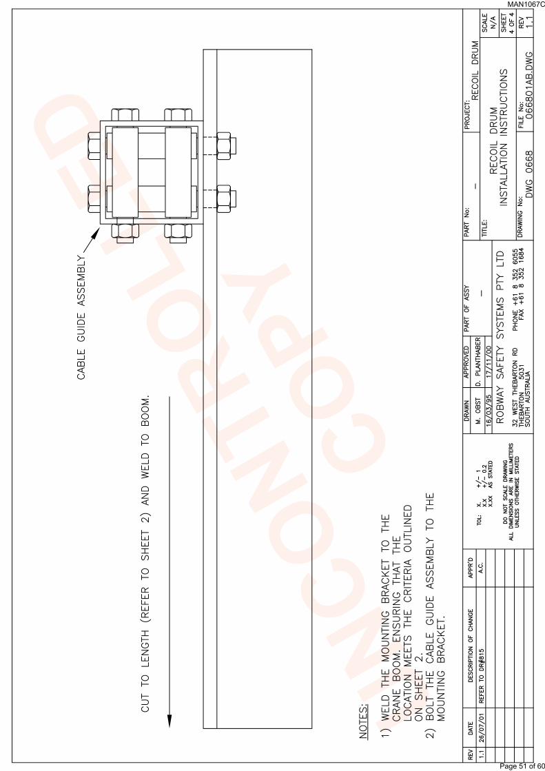
5.3.3. Recoil Drum (Telescopic Cranes Only)
The Recoil Drum contains both the angle and length sensors for telescopic cranes. The payout cable of the drum is also used for wiring the ATB switch/es if required.
Fix the recoil drum and payout cable to the RHS side of the main boom (LH installations require the electronic angle sensor to be repositioned on its mount, refer to recoil drum electrical drawing at rear of this manual) by welding the mounting bolts provided. Mount the recoil drum on the bolts ensuring that the electrical connection socket pointing towards the cabin. Ensure the recoil drum is mounted 'squarely' to the boom side panel, this is essential to avoid incorrect payout wire spooling problems. Select a convenient uninterrupted payout cable alignment along the side of the booms and cut and weld the anchor post provided to a suitable position on the boom head, so that the cable can be clamped into the groove on the post to obtain a temporary line. Select positions for the intermediate cable guides provided, one for each telescoping section and one or more for the main boom allowing 3-4m between the drum and the nearest cable guide. Measure the distance from the cable to the sides of the booms, record lengths and mark the positions for the guides. Cut and weld the guides to the boom after removing the cable. Refit the cable through the eyes and anchor to the post using the clamp provided. Adjust the position of each eye so that the cable passes through just touching the top of the ring. When booms deflect and pads wear the cable will take up a lower position in the eye.
Maximize the recoil drum spring tension by releasing the payout cable from the boom tip and extend until the spring 'locks up' (boom must be fully extended). Return 2 turns back onto the recoil drum. Cut off excess payout cable and re-terminate back onto the boom tip stand-off securing bracket
Remove the cover from the recoil drum. Fully retract the boom and turn the large gear attached to the recoil drum length potentiometer back to minimum position. Verify the start position by viewing the uncalibrated length (refer to the Function Code list at the rear of this manual). Nominally, about 50 raw counts is a good starting point. Fully extend the boom to check continuity of length drive. Make sure all mounting bolts for reeling drum are tight. Replace cover on reeling drum.
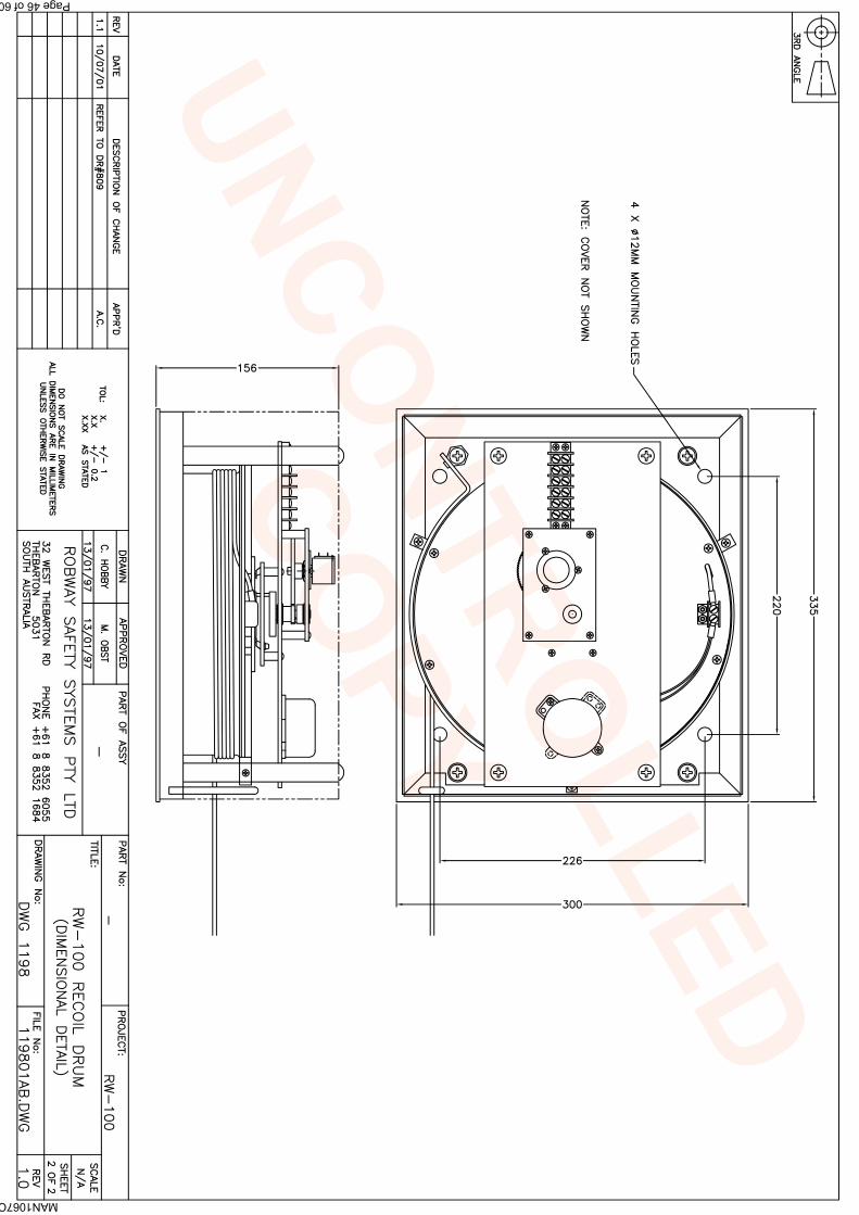
Drawing Reference:DWG 2488 (Sheet 1-2 of 2) – “RW-10 Recoil Drum (No ATB), General
Arrangement” DWG 1539 (Sheet 1-2 of 2) – “RW-10 Recoil Drum (with ATB), General
Arrangement” DWG 2159 – “RW-10 (No ATB) Wiring Diagram” DWG 1239 – “RW-10 (with ATB) Wiring Diagram, General Arrangement” DWG 1198 (Sheet 1-2 of 2) – “RW-100 Recoil Drum, General Arrangement” DWG 1199 – “RW-100 Wiring Diagram, General Arrangement”
MAN1067C
Page 17 of 60
Robway Crane Safety Systems Pty Ltd Adelaide, South Australia
Fix the anti-two-block (ATB) switch mounting pin by bolting or welding it to the boom head preferably so that the bob weight (when suspended from the switch) can be fitted to the static hoist rope below the rope anchor. Check that the switch works correctly as the boom luffs throughout its working range.
Additional switches (for fly-jibs) can be added. Connection is via the bullet-type connectors from the cable. When more than one ATB switch is required (e.g. main & fly), connect the ATB cables of the switches in series via the bullet-type connectors.
Hang the bob weight assembly from the switch eye after cutting the chain to length if desired to suit winch line speed. Repeat the procedure if required for rooster or fly jib.
The sensor cables are shielded instrumentation cables and are normally quite robust. They should be treated with care, however, as even a small amount of damage can be very costly due to down-time or intermittent behaviour. Always support the cable in such a way that there is no "excessive" strain applied, such as tension or flexing. The cable should be strapped to a fixed member that it runs along, unless it is held within a cable tray or trunking. The cable should be clipped at 600mm intervals. Avoid sharp bends such as around a sharp corner. Where there is to be flexing, the installer must ensure that the bending is reduced to an absolute minimum to avoid fatigue breakage of the conductors.
5.3.7. Connectors
It is recommended that the installer applies a suitable silicone grease (e.g., Dow Corning 4 “Electrical Insulating Compound”) on the plugs and sockets prior to connecting the cables. The silicone grease should be smeared across the connector contact points to increase the water proofing of the connector.
5.3.8. Motion Cut Control Wiring
The 1450 System provides an output signal that can be utilised for crane motion control if required.
The ampere rating of this signal is approx 1 ampere only and must not be
used to directly operate hydraulic or mechanical solenoid devices or high
MAN1067C
Page 18 of 60
Robway Crane Safety Systems Pty Ltd Adelaide, South Australia
1450 Manual
capacity relays. For such devices a “slave” relay must be used to switch
ampere ratings exceeding 1 ampere.
This signal is at ‘negative polarity’ when all is normal and no alarm state
exists. In alarm, this signal will “float” causing the motion-cut switching
device to drop out through loss of sufficient voltage potential across the
coil.
If motion cut is required the client shall provide appropriate solenoids (or relay devices) to de-activate the appropriate function and wire them as shown per the drawings at the back of this manual.
A typical automotive type relay (contact rating of 10 amperes) can be used as a “slave relay”. Most of these relays usually have 5 push-on spade type connections, 2 for coil +ve and –ve and 3 for the relay contacts, one for common (COM) , one for normally closed (NC) and one for normally open (NO) condition. The coil voltage must match the crane electrics.
Drawing Reference: DWG 1011 – “1400 Series Motion Cut Control Wiring”
1. Permanent display damage may occur if incorrect motion-cut connections are made.
2. POWER MUST BE DISCONNECTED before attempting connections.
3. NEVER insert larger capacity fuses than those originally supplied.
4. Obtain specialist assistance if you are unfamiliar with crane electrics.
MAN1067C
Page 19 of 60
Robway Crane Safety Systems Pty Ltd Adelaide, South Australia
1450 Manual
6. Calibration
After installing the 1450 System modules, the unit must be calibrated to ensure accurate load measurement. The following sections explain how it is done.
Before calibrating the 1450, make sure that all system modules are correctly installed as described in Section 5. “Installation” and attached drawings.
Procedures in the following sections can only be used while in CALIBRATION MODE.
To enter CALIBRATION MODE you have to SWITCH OFF the 1450 unit, then press and hold the CANCEL button WHILE SWITCHING ON the unit. You should release the CANCEL button after hearing the first beep from the unit.
If CALIBRATION MODE is successfully entered the 1450 will show “F-00” on the display. If the message does not show, repeat procedure.
Once in calibration mode all procedures are activated via a FUNCTION CODE. Each FUNCTION CODE enables ONE procedure. A list of available FUNCTION CODES can be found at the rear of this manual.
Note that the FUNCTION CODE listing can be different from application to application and therefore the one supplied with this manual must always be
used.
To select a FUNCTION CODE use the UP/DOWN arrows to select its code then press the ENTER button in the lower right corner of the display. Once a function code is selected and the ENTER key pressed you are expected to enter a new value for the function code selected.
Normally the current value of the function is used as the starting value. You have the option of using the UP/DOWN arrow keys to change this value or can press the CANCEL or the ENTER keys.
If the CANCEL button is pressed the operation will be cancelled and previous calibration value will be retained, the 1450 should return to the F-xx prompt.
If the ENTER key is pressed, however, the last value shown in the window will be accepted and calibration data changed accordingly.
MAN1067C
Page 20 of 60
Robway Crane Safety Systems Pty Ltd Adelaide, South Australia
1450 Manual
6.1. Correct Order of Procedures
When calibrating the 1450, the installer should follow the following order of procedures.
1. Enter correct crane geometry details,
F-13 – Slew Offset F-14 – Distance Between Foot Pin & Centre of Main Boom
Sheave F-15 – Main Sheave Radius F-16 – Distance Between Jib Centre Line & Centre of Jib Sheave F-17 – Jib Sheave Radius
2. Verify sensor operation,
F-01 – Raw Counts of Angle Sensor Input F-05 – Raw Counts of Length Sensor Input (if telescopic crane) F-09 – Raw Counts of Slew Encoder Input (if slew encoder
F-07 – Calibrate Short Boom Length F-08 – Calibrate Long Boom Length
5. Apply radius correction, if required (telescopic cranes only),
F-10 – Correct Radius for Winch Selected
6. Apply averagingof samples if needed,
This function code (F-11) may be used to improve stability of sensor readout (only if display readout seems erratic). Factory default setting is “0” and can be changed with this function code. Maximum setting is “25”.
7. Configure motion cut activation if required,
F-18 – Enable/Disable Motion Cut on Anti-Two-Block (ATB) F-19 – Enable/Disable Motion Cut on Limits
MAN1067C
Page 21 of 60
Robway Crane Safety Systems Pty Ltd Adelaide, South Australia
1450 Manual
6.2. Function Codes Described
This section describes the individual calibration functions in more detail.
6.2.1. Exit Calibration Mode (F-00)
This function is normally used after all desired calibration functions have been completed. Once selected the 1450 exits calibration mode and re-enters normal operating mode.
Exiting calibration mode can also be achieved by pressing the CANCEL key while the F-xx prompt is shown in the display window.
6.2.2. View Uncalibrated Angle Input (F-01)
Use this function code to view the “raw data” or “raw count” of the angle input signal. Signal from the angle sensor is converted to a number in the range of 0 - 1023 by the 1450. The valid working range of the sensor is 33 to 999, i.e. the raw data should vary within 33 to 999 counts between the minimum and maximum angle. This can be verified by viewing this function while luffing the boom throughout its full operating range.
Raw data below 33 represents a short circuit in the sensor (or in the cable), and counts above 999 (typically 1023) refers to an open circuited sensor (or break in the cable). Refer to Section 7. “Troubleshooting” and correct the problems prior to calibrating the angle sensor.
While this function is active you can disable the angle channel by pressing the ENTER key. This will instruct the computer to ignore input from the angle sensor. It will remain in this mode until the ENTER key is pressed again while in this function.
When the angle channel is disabled, the OFF message will be shown as a reminder. Press the CANCEL key to exit this function.
6.2.3. View Calibrated Angle Input (F-02)
This function is only useful when you want to look at the actual angle without leaving calibration mode. Remember that calibration mode can only be entered by switching the 1450 off and then on again. This may not always be desirable or practical. In such cases use this function to look at the actual angle in degrees.
While this function is active you can disable the angle channel by pressing the ENTER key. This will instruct the computer to ignore input from the angle sensor. It will remain in this mode until the ENTER key is pressed again while in this function.
When the angle channel is disabled, the OFF message will be shown as a reminder. Press the CANCEL key to exit this function.
MAN1067C
Page 22 of 60
Robway Crane Safety Systems Pty Ltd Adelaide, South Australia
1450 Manual
6.2.4. Calibrate Low Angle (F-03)
Use this function to calibrate the low angle as follows:
Safely luff the boom down to a low angle, e.g. 30°,
Enter calibration mode, if not already activated, and select the correct function code (F-03) for calibrating low boom angle,
Accurately measure the actual boom angle using an angle finder,
Use the UP/DOWN keys to ramp the display to the required value then press ENTER to accept this value.
6.2.5. Calibrate High Angle (F-04)
Use this function to calibrate the low angle as follows:
Safely luff the boom up to a high angle, e.g. 65°,
Enter calibration mode, if not already activated, and select the correct function code (F-04) for calibrating high boom angle,
Accurately measure the actual boom angle using an angle finder,
Use the UP/DOWN keys to ramp the display to the required value then press ENTER to accept this value.
Use this function code to view the “raw data” or “raw count” of the length input signal. Signal from the length sensor is converted to a number in the range of 0 - 1023 by the 1450. The valid working range of the sensor is 33 to 999, i.e. the raw data should vary within 33 to 999 counts between the short (fully retracted) and long (fully extended) boom length. This can be verified by viewing this function while telescoping the boom from fully retracted to its full extension.
Raw data below 33 represents a short circuit in the sensor (or in the cable), and counts above 999 (typically 1023) refers to an open circuited sensor (or break in the cable). Refer to Section 7. “Troubleshooting” and correct the problems prior to calibrating the boom length sensor.
While this function is active you can disable the length channel by pressing the ENTER key. This will instruct the computer to ignore input from the length sensor. It will remain in this mode until the ENTER key is pressed again while in this function.
When the length channel is disabled, the OFF message will be shown as a reminder. Press the CANCEL key to exit this function.
This function is only useful when you want to look at the actual boom length without leaving calibration mode. Remember that calibration mode can only be
MAN1067C
Page 23 of 60
Robway Crane Safety Systems Pty Ltd Adelaide, South Australia
1450 Manual
entered by switching the 1450 off and then on again. This may not always be desirable or practical. In such cases use this function to look at the actual boom length in metres.
While this function is active you can disable the length channel by pressing the ENTER key. This will instruct the computer to ignore input from the length sensor. It will remain in this mode until the ENTER key is pressed again while in this function.
When the length channel is disabled, the OFF message will be shown as a reminder.
Press the CANCEL key to exit this function.
6.2.8. Calibrate Short Boom Length (F-07) – Telescopic Cranes Only
Use this function to calibrate the short boom length as follows:
Fully retract the main boom,
Enter calibration mode, if not already activated, and select the correct function code (F-07) for calibrating short boom length,
Check the fully retracted value of the main boom from the crane’s charts,
Use the UP/DOWN keys to ramp the display to the fully retracted value then press ENTER to accept this value.
6.2.9. Calibrate Long Boom Length (F-08) – Telescopic Cranes Only
Use this function to calibrate the short boom length as follows:
Fully extend the main boom,
Enter calibration mode, if not already activated, and select the correct function code (F-08) for calibrating long boom length,
Check the fully extended value of the main boom from the crane’s charts,
Use the UP/DOWN keys to ramp the display to the fully extended value then press ENTER to accept this value.
6.2.10. View Shaft Encoder Raw Counts (F-09)
Use this function to view the raw data or raw count of the slew encoder.
While this function is active you can disable the encoder input signal by pressing the ENTER key. This will instruct the computer to ignore input from the encoder. It will remain in this mode until the ENTER key is pressed again while in this function.
When the encoder signal is disabled, the OFF message will be shown as a reminder. Press the CANCEL key to exit this function.
MAN1067C
Page 24 of 60
Robway Crane Safety Systems Pty Ltd Adelaide, South Australia
1450 Manual
6.2.11. Correct Radius for Winch Selected (F-10) – Telescopic Cranes Only
Use this function to correct the radius readout for the winch selected (main or aux).
6.2.12. Select Number of Samples to Average (F-11)
This function allows you to stabilise the displayed angle and length readouts in the event the numbers are changing erratically. It is mainly used for display filtering purposes. Default value from factory is “0”, and maximum number settable is “25”.
6.2.13. Clear All Calibration Data (F-12) – USE EXTREME CAUTION!
Activating this function will clear all the calibration data. Any on-site changes made will be lost. This must only be used by Robway-trained personnel for troubleshooting purposes.
6.2.14. Slew Offset (F-13)
Slew offset is the horizontal distance between boom foot pin and centre of slew. The value is “negative” if foot pin is behind the centre of rotation or slew, and “positive” if foot pin is at the front of the centre of rotation.
Measure and enter the value of slew offset in this function code.
6.2.15. Distance Between Foot Pin and Centre of Main Boom Sheave (F-14)
Measure as per the illustration below and enter the value in this function code.
6.2.16. Main Sheave Radius (F-15)
Measure and enter the value in this function code.
6.2.17. Distance Between Jib Centre Line and Centre of Jib Sheave (F-16)
Measure as per the illustration below and enter the value in this function code.
MAN1067C
Page 25 of 60
Robway Crane Safety Systems Pty Ltd Adelaide, South Australia
1450 Manual
6.2.18. Jib Sheave Radius (F-17)
Measure and enter the value in this function code.
6.2.19. Enable/Disable Motion Cut on Anti-2-Block (F-18)
The ENTER key is used to toggle between ENABLE and DISABLE. Press ENTER to toggle to desired configuration and then press CANCEL to exit function.
6.2.20. Enable/Disable Motion Cut on Limits (F-19)
The ENTER key is used to toggle between ENABLE and DISABLE. Press ENTER to toggle to desired configuration and then press CANCEL to exit function.
6.2.21. Retracted Boom Length in Metrew (F-20) – Telescopic Cranes Only
This is used only for calculating radius correction. Altering this value will clear radius correction data. Please see also Section 6.2.11 “Correct Radius for Winch Selected”.
MAN1067C
Page 26 of 60
Robway Crane Safety Systems Pty Ltd Adelaide, South Australia
1450 Manual
7. Troubleshooting
The 1450 system incorporates a number of software features that are designed to help
the service person quickly identify a fault, however it must be stressed that these features cannot identify everything. They can only be used as a guide to identify additional checks that can be made. Some notes are provided below, followed by some example faults and possible causes.
1. Identify the symptoms. Take time to find out exactly what is happening to indicate a problem. If possible have the problem demonstrated so you can "describe it in your own words". Sometimes what someone else has told you is only part of the story.
2. Leave the calibration alone! Too many times a re-calibration has been attempted in order to rectify a problem before that problem has been correctly identified. This leads to added confusion as the perspective is generally moved from the real fault to "calibration problems". We have often received a message indicating that our display has "not accepted the calibration data". Most times this is due to a fault in a cable or sensor which was not identified prior to re-calibration. Re-calibration must only be performed when all physical inputs have been verified for correct operation, and in actual fact is rarely ever needed.
3. Do you have your simulator with you? A simulator is a very quick way to verify if the fault is external to the display and will save you a lot of heartache.
4. Have you read the manual? When all else fails, read the manual! Your answer may actually be in there.
5. Know what information you need to gather. If you collect the correct information from the display the job is half done. Before you begin to suspect faults with the system, you must satisfy yourself that the display is correctly configured for the crane environment. In other words, check that the limits are set correctly. Are all of the sensors connected? In general if sensors have been supplied with the system, they must always be connected. The display will check them continuously and issue an error if that sensor cannot be detected. Check your length, angle, radius, and slew limits to verify that the equipment is permitted to be in that situation. If there is still a problem once these have been checked, then you will need to check the hardware.
6. The main pieces of useful information obtainable from the displays are
the raw counts. The raw count shows what the actual inputs are doing (i.e. like a signal strength indication). These raw counts are manipulated in software according to the calibration data stored in the display to produce the readouts on the Display Unit. If the calibration has been done incorrectly, or the configuration is incorrect, or something else is wrong, then the Display Unit readouts (e.g. the ANGLE or LENGTH values) may provide
you with misleading information. YOU MUST USE THE "VIEW
UNCALIBRATED...." FUNCTION CODES TO DETERMINE THE
CORRECT OPERATION OF THE EXTERNAL SENSORS, NOT THE
"CALIBRATED" VALUES. For correct operation these values must be in
MAN1067C
Page 27 of 60
Robway Crane Safety Systems Pty Ltd Adelaide, South Australia
1450 Manual
the range 33 to 999. Anything outside of this range will produce an error. Refer to Section 6. “Calibration” on how to access these raw counts.
7. Check the obvious. Once you have found a problem with a sensor for example, check all of the obvious things to do with that sensor such as making sure all of the connectors are tight. Be systematic - make notes about what you have done and what you found. You will find that under pressure you can easily forget what you have checked and it becomes very easy to miss things.
MAN1067C
Page 28 of 60
Robway Crane Safety Systems Pty Ltd Adelaide, South Australia
1450 Manual
EXAMPLE PROBLEMS AND POSSIBLE CAUSES
Problems That Produce Error Codes:
Error code 101.
This is indicating that the signal from the angle sensor is too low or too high. This should be confirmed by viewing the UNCALIBRATED ANGLE INPUT and noting that the value shown in the LOAD display is less than 33, or greater than 999.
Possible causes:
Angle sensor incorrectly mounted. This is especially critical for the Electronic Angle Sensor. Refer to Section 6. “Installation” of the manual for installation of the angle sensor.
The angle sensor signal wire is short circuited to the shield or to the angle 0V.
The angle sensor signal wire is shorted to the excitation positive wire.
The angle sensor is not connected or there is an open circuit in either the angle sensor signal wire or the angle excitation positive wire.
The angle sensor excitation voltage is shorted. If this is the case it will also affect the length and load channels.
The angle sensor 0V wire is open circuit.
Error code 110.
This is indicating that the signal from the length sensor is too low or too high. This should be confirmed by viewing the length raw counts and noting that the "r" value is less than 33, or greater than 999.
Possible causes:
The length potentiometer may not have been set up as per the manual. Refer to the manual for the installation of the length sensor, particularly the initial rotation of the gear wheel by 1/8 of a turn.
The length sensor signal wire is short-circuited to the shield or to the length 0V.
The length sensor signal wire is short-circuited to the excitation positive wire.
The length sensor is not connected or there is an open circuit in either the length sensor signal wire, the length excitation positive wire, or the length 0V wire.
Payout cable may have broken.
The length sensor excitation voltage is shorted. If this is the case, it will also affect the angle channel.
Error code 301.
This is indicating that the angle being measured is outside of its allowed range.
MAN1067C
Page 29 of 60
Robway Crane Safety Systems Pty Ltd Adelaide, South Australia
1450 Manual
Possible causes:
A genuine violation of the angle limits has occurred. The angle sensor mounting may have loosened allowing the sensor
to move. Check the angle displayed against the actual angle of the boom.
Error code 302.
This is indicating that the length being measured is outside of its allowed range.
Possible causes:
A genuine violation of the length limits has occurred.
The length potentiometer mounting may have loosened allowing the sensor to move.
Check the length displayed against the actual boom length.
Payout cable may have fallen off the reeling drum.
Payout cable may have been broken or become tangled.
Error code 304.
This is indicating that the radius being measured is outside of its allowed range.
Possible causes:
A genuine violation of the radius limits has occurred. Check as per Error Code 301 and 302.
Error code 310.
This is indicating that the slew zone being detected is outside of its allowed range.
Possible causes:
A genuine violation of the slew zone limit has occurred.
The orientation or position of the slew switch is incorrect. The slew switch is incorrectly wired.
The slew switch or the cable has suffered some damage and is not reading correctly.
Problems That Do Not Produce Error Codes:
When the system starts in the morning the displays are erratic, but settle
during the day.
This is a common sign of moisture ingress into either the display, the connectors, the sensors or the cable. These should be checked, dried and sealed.
The display does not start.
MAN1067C
Page 30 of 60
Robway Crane Safety Systems Pty Ltd Adelaide, South Australia
1450 Manual
You should check the power supply. Refer to the manual for allowable voltage ranges. If these are correct you may need to open the Control Unit and check the fuses.
The unit is on alarm, but no error code on display.
Check for Two blocking condition. If no Two Blocking condition exist but the ATB LED on display is ON,
check the “earth lead” from the display for proper grounding to crane chassis.
If “earth lead” is OK, check the ATB switch and cable for faults.
MAN1067C
Page 31 of 60
Robway Crane Safety Systems Pty Ltd Adelaide, South Australia