Page 1
15-447 Computer Architecture Fall 2007 ©
Sep 10th, 2007
Majd F. [email protected]
www.qatar.cmu.edu/~msakr/15447-f07/
CS-447– Computer Architecture
M,W 10-11:20am
Lecture 4Instruction Set Architecture
Page 2
15-447 Computer Architecture Fall 2007 ©
Done by nowDone by now
°Read the first 3 chapters of the book
°Review the slides
°Come see us during office hours
°Working on the project
Page 3
15-447 Computer Architecture Fall 2007 ©
Program Concept
°Hardwired systems are inflexible
°General purpose hardware can do different tasks, given correct control signals
° Instead of re-wiring, supply a new set of control signals
Page 4
15-447 Computer Architecture Fall 2007 ©
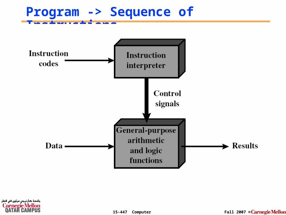
What is a program?°A sequence of steps
°For each step, an arithmetic or logical operation is done
°For each operation, a different set of control signals are needed
Page 5
15-447 Computer Architecture Fall 2007 ©
Execution of a Program
Page 6
15-447 Computer Architecture Fall 2007 ©
Program -> Sequence of Instructions
Page 7
15-447 Computer Architecture Fall 2007 ©
Function of Control Unit°For each operation a unique code is provided
• e.g. ADD, MOVE
°A hardware segment accepts the code and issues the control signals
°We have a computer!
Page 8
15-447 Computer Architecture Fall 2007 ©
Computer Components: Top Level View
Page 9
15-447 Computer Architecture Fall 2007 ©
Instruction Cycle°Two steps:• Fetch
• Execute
Page 10
15-447 Computer Architecture Fall 2007 ©
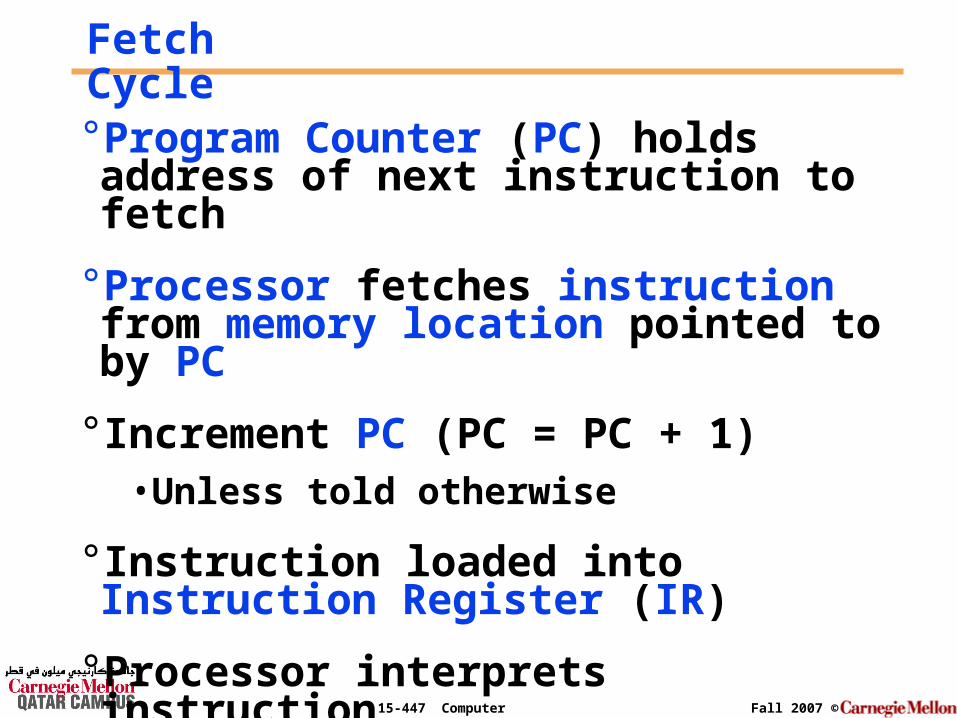
Fetch Cycle°Program Counter (PC) holds address of next instruction to fetch
°Processor fetches instruction from memory location pointed to by PC
° Increment PC (PC = PC + 1)• Unless told otherwise
° Instruction loaded into Instruction Register (IR)
°Processor interprets instruction
Page 11
15-447 Computer Architecture Fall 2007 ©
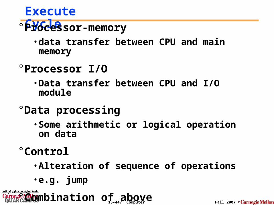
Execute Cycle° Processor-memory
• data transfer between CPU and main memory
° Processor I/O• Data transfer between CPU and I/O module
° Data processing• Some arithmetic or logical operation on data
° Control• Alteration of sequence of operations
• e.g. jump
° Combination of above
Page 12
15-447 Computer Architecture Fall 2007 ©
Instruction Set Architecture
I/O systemProcessor
CompilerOperating
System(Windows XP)
Application (MediaPlayer)
Digital DesignCircuit Design
Instruction Set Architecture
Datapath & Control
Transistors
MemoryHardware
Software Assembler
Layout & Technology
The Language ofthe Computer
Page 13
15-447 Computer Architecture Fall 2007 ©
Chapter objectives
°The goal of this lecture is to discuss an instruction set (a simple one), showing both how instructions are represented in hardware & the relationship between high-level programming languages (for example C-language which you know) and this more primitive one.
°Next time: the different addressing modes.
Page 14
15-447 Computer Architecture Fall 2007 ©
°By learning how to represent instructions, you will also discover the secret of computing: the stored-program concept.
Chapter objectives (2)
Page 15
15-447 Computer Architecture Fall 2007 ©
Translating & Starting a Program
C Program
Compiler
Assembly Language Program
Assembler
Object: Machine language module
Linker
Executable: Machine language program
Page 16
15-447 Computer Architecture Fall 2007 ©
Translating & Optimizing a Program: The Compiler
The Compiler transforms the C program into an assembly language program, a symbolic form of what the machine understands.
Page 17
15-447 Computer Architecture Fall 2007 ©
Translating a Program: The Assembler
The Assembler transforms the
Assembly program into a machine language module.
Page 18
15-447 Computer Architecture Fall 2007 ©
Stitching a Program: The Linker
The linker or link editor takes all the independently assembled machine language programs and “stitches” them together.
There are three steps for the linker: 1) Place code and data modules symbolically
in memory2) Determine the addresses of data and instruction labels3) Patch both the internal and external references
Page 19
15-447 Computer Architecture Fall 2007 ©
What Happens in Hardware?
CPU Memory
Instructions
Data
Page 20
15-447 Computer Architecture Fall 2007 ©
Address Bus & Data Bus
DataBus
AddressBus
CPU Memory
Page 21
15-447 Computer Architecture Fall 2007 ©
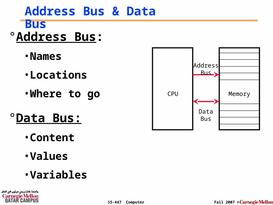
Address Bus & Data Bus
DataBus
AddressBus
CPU Memory
°Address Bus:
• Names
• Locations
• Where to go
°Data Bus:
• Content
• Values
• Variables
Page 22
15-447 Computer Architecture Fall 2007 ©
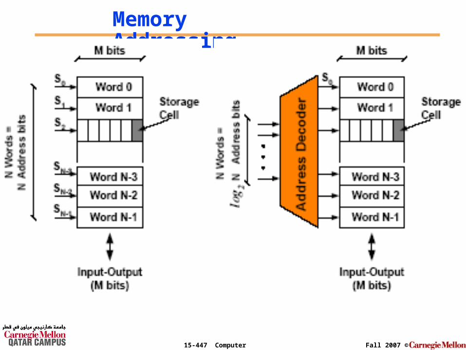
Memory Addressing
Page 23
15-447 Computer Architecture Fall 2007 ©
Example of Memory with AddrBus = 1
Decoder1 to 2
Memory
01
DataBus = 1
Decoder1 to 2
Memory
01
DataBus = 2
Address Bus = 1 Address Bus = 1
Page 24
15-447 Computer Architecture Fall 2007 ©
Example of Memory with AddrBus = 1
Decoder1 to 2
Memory
01
Address Bus = 1 Data Bus = 8
Page 25
15-447 Computer Architecture Fall 2007 ©
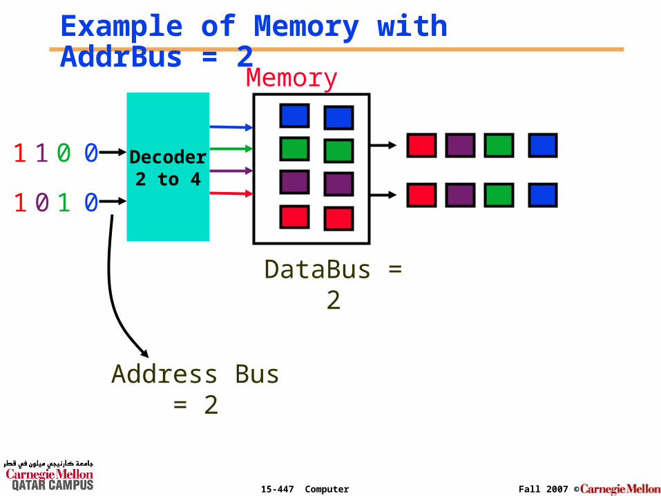
Example of Memory with AddrBus = 2
Decoder2 to 4
Memory
0
1
DataBus = 1
0
0
0
1
1
1
Address Bus = 2
Page 26
15-447 Computer Architecture Fall 2007 ©
Decoder2 to 4
Memory
0
1
DataBus = 2
0
0
0
1
1
1
Example of Memory with AddrBus = 2
Address Bus = 2
Page 27
15-447 Computer Architecture Fall 2007 ©
Decoder2 to 4
Memory
0
1
DataBus = 8
0
0
0
11
1
Example of Memory with AddrBus = 2
Address Bus = 2
Page 28
15-447 Computer Architecture Fall 2007 ©
How does the Memory look like?
Location/Address ContentEnglish Decimal Binary Decimal BinaryML0 0 000000 425 00010101001ML1 1 000001 212 00011010100ML2 2 000010 23 00000010111….….
…. ….
….….
……
……
ML61 61 111101 2047 11111111111ML62 62 111110 69 00000000101ML63 63 111111 1559 11000010111
Page 29
15-447 Computer Architecture Fall 2007 ©
Memory Addresses Vs Memory Content
As shown in the memory table:
# locations = 64 (ML0 to ML63)=> memory require 6-bits to address
if the memory word-size = 11-bits => largest content in memory is 2048
Page 30
15-447 Computer Architecture Fall 2007 ©
In General we Need
2#bits
= # Memory Locations
If we wish to have 120 locations (120 names),
then 7-bits should be dedicated to address
them (27 = 128)
If we first decide to dedicate 6-bits to address the memory
locations, then we will be limited to 64 in their number
(26 = 64)
Page 31
15-447 Computer Architecture Fall 2007 ©
Instruction Set Design
DataBus
AddressBus
CPU Memory
ControlRegisterFile
FunctionalUnits
IR
PC
Instructions
Data
Page 32
15-447 Computer Architecture Fall 2007 ©
What is an instruction set?
° The complete collection of instructions that are understood by a CPU
° Machine Code
° Binary
° Usually represented by assembly codes
Page 33
15-447 Computer Architecture Fall 2007 ©
Elements of an Instruction
° Operation code (Op code)• Do this operation
° Source Operand reference• To this to this value
° Result Operand reference• Put the answer here
Page 34
15-447 Computer Architecture Fall 2007 ©
Operation Code (page 342)
° Operation code(Opcode)
• Do this operation
Name Mnemonic
Addition ADD
Subtraction SUB
… …
Multiply MULT
Page 35
15-447 Computer Architecture Fall 2007 ©
Processor Operations:
Data processing
Data storage
Data movement
Program flow
control
°Add
°Sub
°Load
°Store
°Read
°Write
°GoTo
°BranchIfIn total, the # of instructions desired is 8, and these require 3-bits for controlling.
Page 36
15-447 Computer Architecture Fall 2007 ©
Registers & How Big?
° CPU must have some working space (temporary storage)
° Number of Registers varies between processor designs
° Large enough to hold full address
° Large enough to hold full data word
Page 37
15-447 Computer Architecture Fall 2007 ©
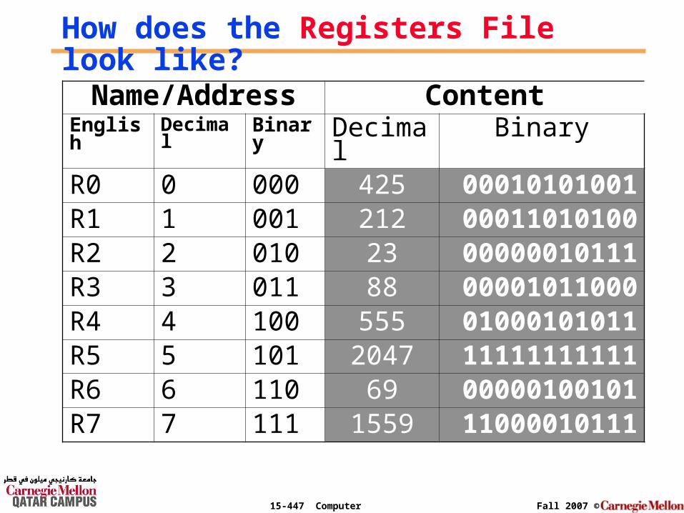
How does the Registers File look like?
Name/Address ContentEnglish Decimal Binary Decimal BinaryR0 0 000 425 00010101001R1 1 001 212 00011010100R2 2 010 23 00000010111R3 3 011 88 00001011000R4 4 100 555 01000101011R5 5 101 2047 11111111111R6 6 110 69 00000100101R7 7 111 1559 11000010111
Page 38
15-447 Computer Architecture Fall 2007 ©
Register Address Vs Register Content
As shown in the register file:
# registers = 8 (R0 to R7)=> registers require 3-bits to address
if the register size = 11-bits=> largest content in registers is 2047
Page 39
15-447 Computer Architecture Fall 2007 ©
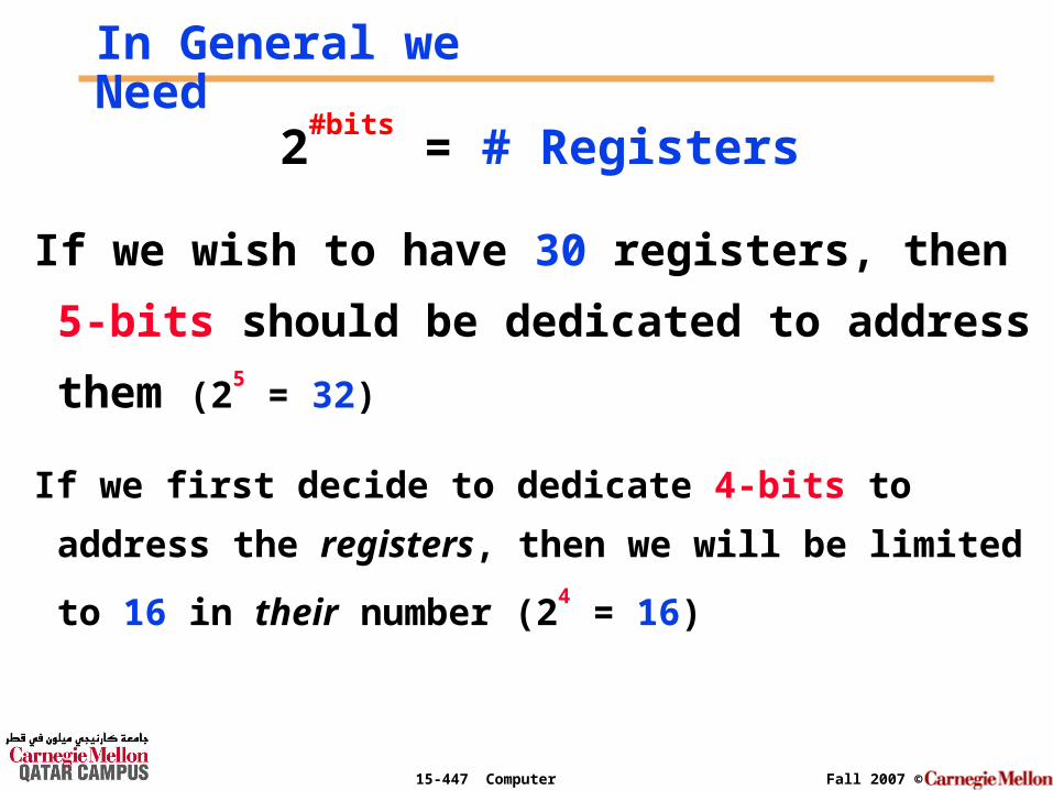
In General we Need
2#bits
= # Registers
If we wish to have 30 registers, then 5-bits
should be dedicated to address them (25 = 32)
If we first decide to dedicate 4-bits to address the
registers, then we will be limited to 16 in their number (24
= 16)
Page 40
15-447 Computer Architecture Fall 2007 ©
Instruction Design
Data processin
g
Data storage
Data movement
Program flow control
Sub 000
Load 010
Read 100
GoTo 110
Add 001
Store 011
Write
101
BranchIf
111
I want this operation to make the additionof two registers & place the result in a third one
Example: Add R1, R2, R3 ; R1 = R2 + R3
Page 41
15-447 Computer Architecture Fall 2007 ©
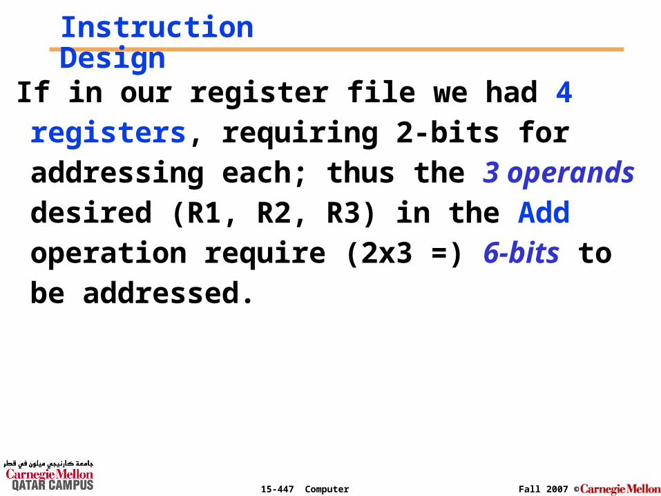
Instruction Design
If in our register file we had 4 registers, requiring 2-bits for addressing each; thus the 3 operands desired (R1, R2, R3) in the Add operation require (2x3 =) 6-bits to be addressed.
Page 42
15-447 Computer Architecture Fall 2007 ©
Instruction Design: Add R0, R4, R11Add R1, R2, R3
001 01 10 11
OpCode Destination
Register
Source
Register
Source
Register
3-bits 2-bits 2-bits 2-bits
9-bits Instruction
Page 43
15-447 Computer Architecture Fall 2007 ©
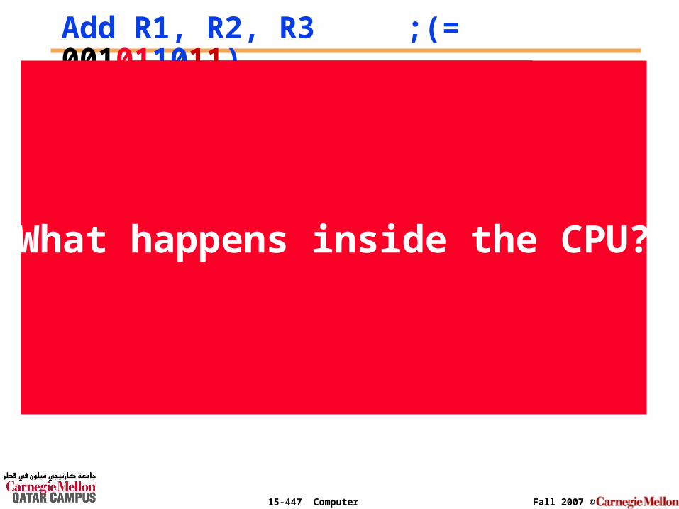
Add R1, R2, R3 ;(= 001011011)
Register File
FunctionalUnits
I.R.
P.C.
001011011
01
23
4
5
67
2
2001011011 001011011
... 3
CPU Memory
What happens inside the CPU?
Page 44
15-447 Computer Architecture Fall 2007 ©
I.R.
P.C.3
001011011
Add R1, R2, R3 ;(= 001011011)
+
010101010
001010101
... R1
R2
R3
010101010 001010101
011111111 NextInstruction
4
CPU
Page 45
15-447 Computer Architecture Fall 2007 ©
Hypothetical Machine
Consider the following hypothetical machine:
# registers = 16 {R0 to R15} require 4-bits to address them (24 = 16)
# memory locations = 256 {M0 to M255} require 8-bits to address them (28 = 256)
Page 46
15-447 Computer Architecture Fall 2007 ©
Hypothetical Machine (cont’d)
# instructions = 32 {Inst0 to Inst31} require 5-bits to be controlled (25 = 32)
where Inst15 = Add (instruction # 15)
& Inst9 = Load (instruction # 9)
Page 47
15-447 Computer Architecture Fall 2007 ©
Example 1: Add R0, R4, R11
Add R0, R4, R11 ; R0 = R4 + R11
01111 0000 0100 1011
And to make it simpler to read and use we will use the Hex notation
F 0 4 B
And the output of the assembler would simply be the following machine code: F04B
Page 48
15-447 Computer Architecture Fall 2007 ©
The instruction
In fact, each piece of an instruction can be considered as an individual number, & placing these numbers side by side forms the instruction.
OpCode Destination Register 1
Source Register 1
Source Register 2
5 bits 4 bits 4 bits 4 bits
17-bit Instruction
Page 49
15-447 Computer Architecture Fall 2007 ©
Example 2: Load R13, 127
Load R13, 127 ; R13 = (127)
01001 1101 0111 1111
And in the Hex notation
9 D 7 F
And the output of the assembler would simply be
the following machine code: 9D7F
Page 50
15-447 Computer Architecture Fall 2007 ©
The instruction
In fact, the instruction format
Example: OpCode, Operand, Operand, Operand
is fixed only for a specific operation
OpCode Register Memory Address
5 bits 4 bits 8 bits
17-bit Instruction
Page 51
15-447 Computer Architecture Fall 2007 ©
Note
° When the OpCode consist of a memory R/W, the
operand, Source Register 1 & 2 are combined to
form the address field of the instruction.
° When the OpCode consist of an immediate
instruction, the operand, Source Register 1 & 2
are combined to form the constant whenever that
is required.
Page 52
15-447 Computer Architecture Fall 2007 ©
The Instruction
°OpCode: basic operation of the instruction
°Destination Register: register where the result of the operations will be loaded
°Source Register 1 & 2: registers where the data will be operated on
Page 53
15-447 Computer Architecture Fall 2007 ©
Instruction size = data word size
As you can see from counting the number of bits, this hypothetical machine instruction takes exactly 17-bits which should be the same size as a data word.
Page 54
15-447 Computer Architecture Fall 2007 ©
Design by Starting with the Instruction SizeWe would like to design a machine with:
• Instruction size = 8 bits
• Instruction number = 8
1. No Operation2. Add3. Sub4. Branch5. Load6. Store7. Increment8. Decrement
3-bits of the instruction word will be reserved to control the 8 desired instructions
x x x
Page 55
15-447 Computer Architecture Fall 2007 ©
So we are left with 5-bits for the operands, With which we can address at most:
• 32 (= 25) memory locations
• 32 (= 25) registers
But if we chose to do so, we will be restricted in the number of operands in the instructions to one
Design by Starting with the Instruction Size
Page 56
15-447 Computer Architecture Fall 2007 ©
On the other hand if we wish to have instructions with 2 explicit operands; that is still possible with the 5-bits left.
Design by Starting with the Instruction Size
x x x
How ? ! ?
Page 57
15-447 Computer Architecture Fall 2007 ©
How ? ! ?
Using bits 3 with 4 and bits 5 with 6 to address 4 registers.
x x x 3 4 5 6 7
Bits Registers addressed # of Registers
3 with 4R1, R2, R3, R4 45 with 6
Page 58
15-447 Computer Architecture Fall 2007 ©
Results°8 Instructions
°2 operands addressing 4 registers with 2-bits each
°1 operand of 5-bits addressing 32 memory locations
Note: # operands increases # registers decreases
Page 59
15-447 Computer Architecture Fall 2007 ©
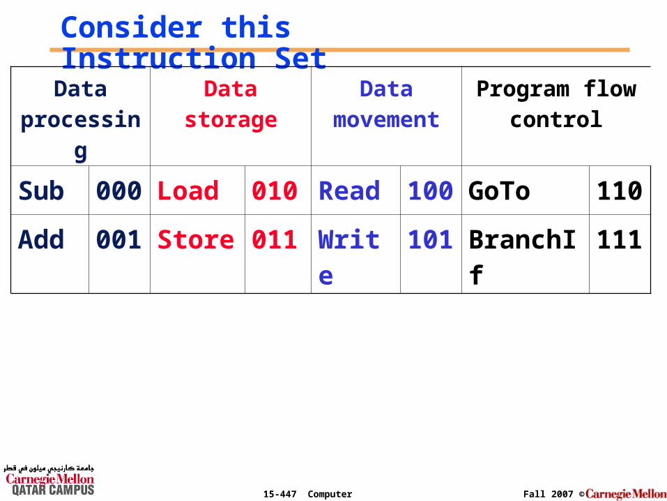
Consider this Instruction Set
Data processin
g
Data storage
Data movement
Program flow control
Sub 000
Load 010
Read 100
GoTo 110
Add 001
Store 011
Write
101
BranchIf
111
Page 60
15-447 Computer Architecture Fall 2007 ©
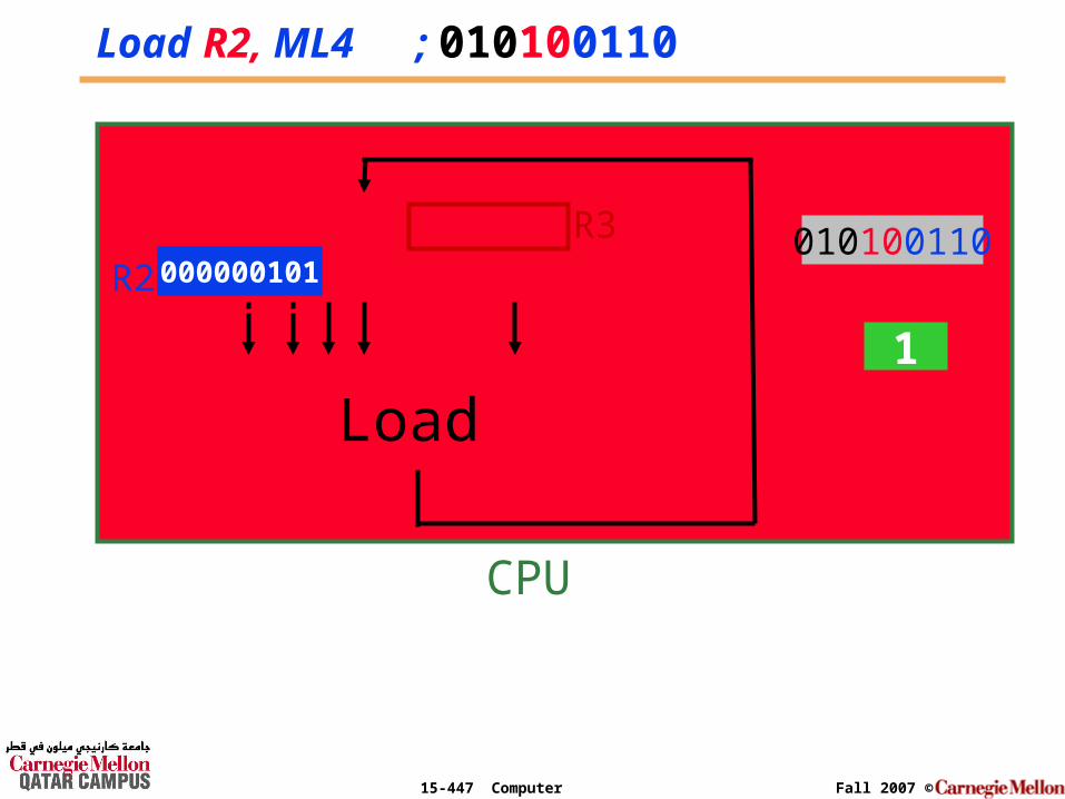
Execution of a simple programThe following program was loaded in memory starting from memory location 0.
0000 Load R2, ML4 ; R2 = (ML4) = 5 = 1012
0001 Read R3, Input14 ; R3 = input device 14 = 7
0010 Sub R1, R3, R2 ; R1 = R3 – R2 = 7 – 5 = 2
0011 Store R1, ML5 ; store (R1) = 2 in ML5
Page 61
15-447 Computer Architecture Fall 2007 ©
The Program in MemoryLoad R2, ML4
010 10 0100Read R3, Input14
100 11 0100Sub R1, R3, R2
000 01 11 10Store R1, ML5
011 01 0101
0 0000 0101001101 0001 1001101002 0010 0000111103 0011 011010111
4 0100 000000101
… … Don’t care14 1011 Input Port15 1111 Output PortAddress Content
Page 62
15-447 Computer Architecture Fall 2007 ©
I.R.
P.C.
010100110
Load R2, ML4 ; 010100110
Load
... R1
R2
R3000000101
0
CPU
1
Page 63
15-447 Computer Architecture Fall 2007 ©
ReadR3, Input14 ; 100110100
Read
... R1
R2
R3
000000101
CPU
12
010100110100110100000000111
Page 64
15-447 Computer Architecture Fall 2007 ©
Sub R1, R3, R2 ; 000011110
Sub
... R1
R2
R3
000000101
CPU
23
100110101
000000111000000101
000000010 000000111 000011110
Page 65
15-447 Computer Architecture Fall 2007 ©
Store R1, ML5 ; 011010111
Don’t Care
... R1
R2
R3
000000101
CPU
34
011010111Next
Instruction000000010 000000111
Store
Page 66
15-447 Computer Architecture Fall 2007 ©
BeforeProgram
Execution
In the Memory
0 0000 0101001101 0001 1001101002 0010 0000111103 0011 0110101114 0100 0000001015 0101 Don’t care… … Don’t care14 1011 Input Port15 1111 Output PortAddress Content
000000010
AfterProgram
Execution