15-447 Computer Architecture Fall 2007 ©
October 22nd, 2007
Majd F. Sakr
[email protected]
www.qatar.cmu.edu/~msakr/15447-f07/
CS-447– Computer Architecture
M,W 10-11:20am
Lecture 14Pipelining (2)
15-447 Computer Architecture Fall 2007 ©
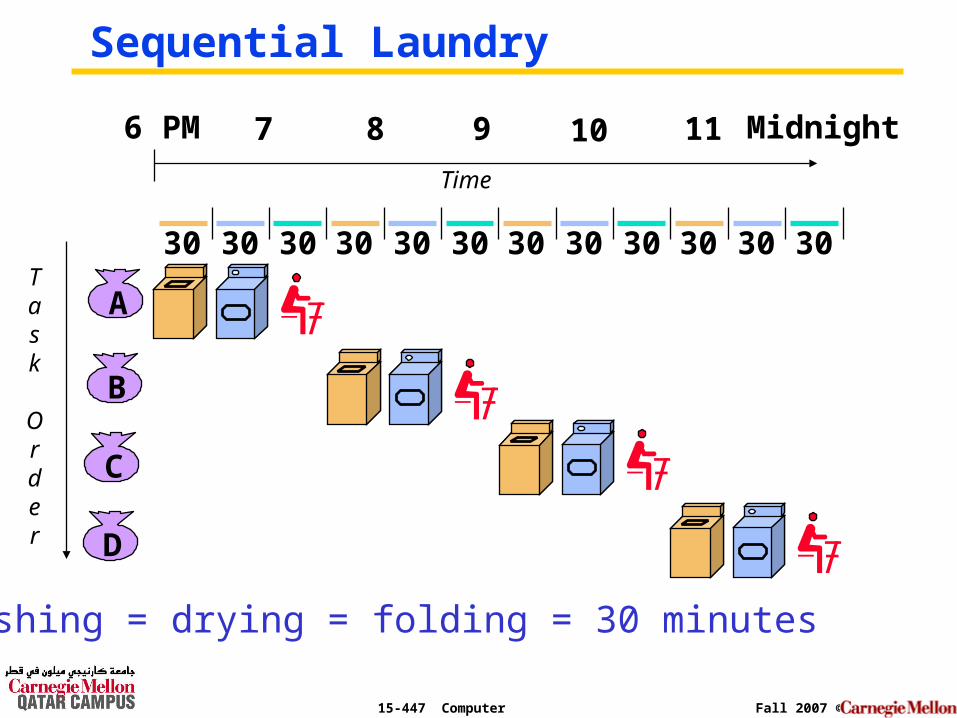
Sequential Laundry
A
B
C
D
6 PM 7 8 9 10 11 Midnight
Task
Order
Time
30 30 30 30 30 30 30 30 30 30 30 30
washing = drying = folding = 30 minutes
15-447 Computer Architecture Fall 2007 ©
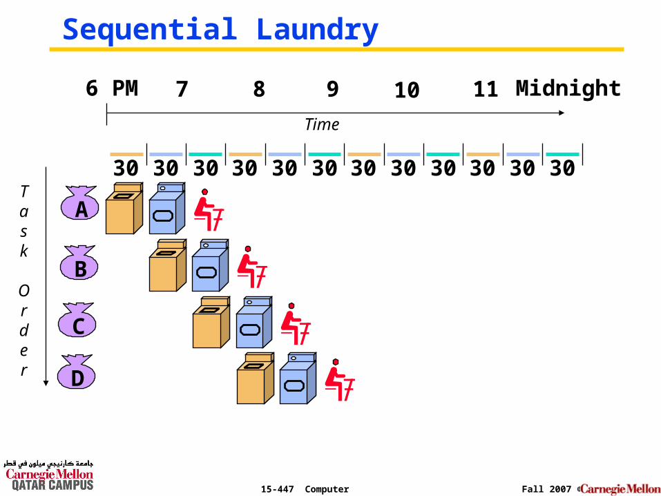
Sequential Laundry
A
B
C
D
6 PM 7 8 9 10 11 Midnight
Task
Order
Time
30 30 30 30 30 30 30 30 30 30 30 30
15-447 Computer Architecture Fall 2007 ©
30 30
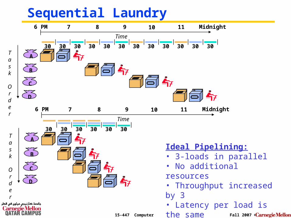
Sequential Laundry
A
B
C
D
6 PM 7 8 9 10 11 Midnight
Task
Order
Time
30 30 30 30
A
B
C
D
6 PM 7 8 9 10 11 Midnight
Task
Order
Time
30 30 30 30 30 30 30 30 30 30 30 30
Ideal Pipelining:• 3-loads in parallel• No additional resources• Throughput increased by 3• Latency per load is the same
15-447 Computer Architecture Fall 2007 ©
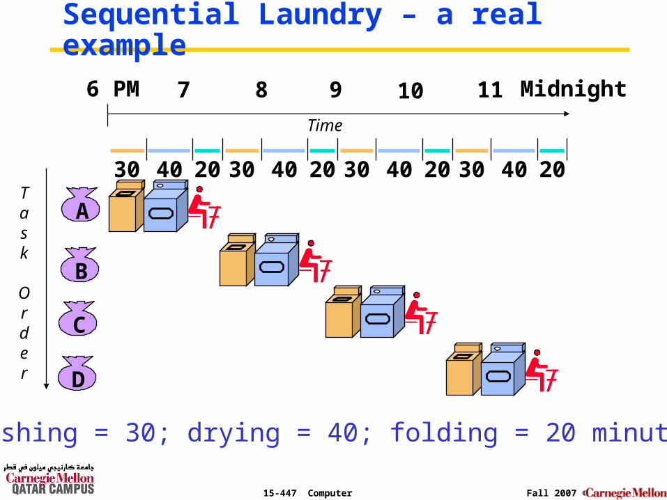
Sequential Laundry – a real example
A
B
C
D
30 40 2030 40 2030 40 2030 40 20
6 PM 7 8 9 10 11 Midnight
Task
Order
Time
washing = 30; drying = 40; folding = 20 minutes
15-447 Computer Architecture Fall 2007 ©
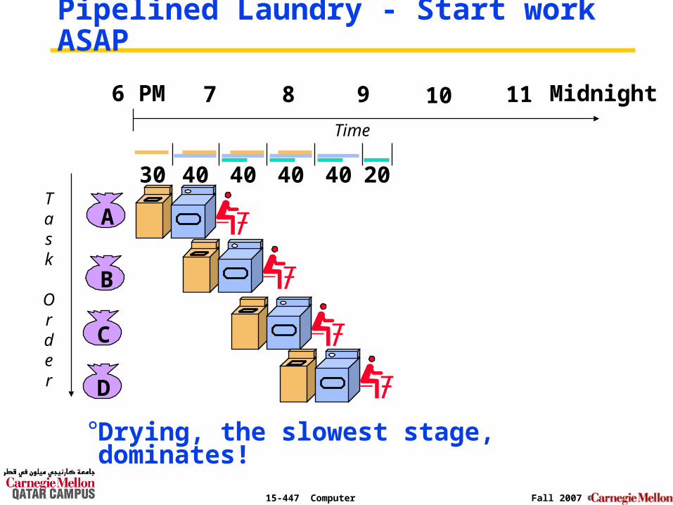
Pipelined Laundry - Start work ASAP
°Drying, the slowest stage, dominates!
A
B
C
D
6 PM 7 8 9 10 11 Midnight
Task
Order
Time
30 40 40 40 40 20
15-447 Computer Architecture Fall 2007 ©
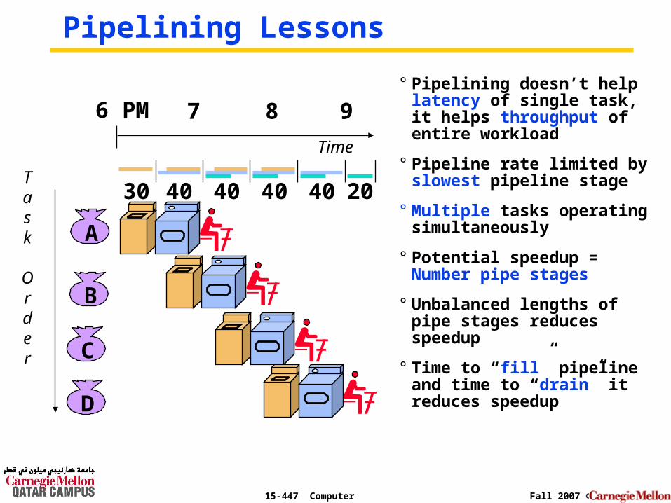
Pipelining Lessons
° Pipelining doesn’t help latency of single task, it helps throughput of entire workload
° Pipeline rate limited by slowest pipeline stage
° Multiple tasks operating simultaneously
° Potential speedup = Number pipe stages
° Unbalanced lengths of pipe stages reduces speedup
° Time to “fill” pipeline and time to “drain” it reduces speedup
A
B
C
D
6 PM 7 8 9
Task
Order
Time
30 40 40 40 40 20
15-447 Computer Architecture Fall 2007 ©
Pipelining
° Doesn’t improve latency!
° Execute billions of instructions, so throughput is what matters!
15-447 Computer Architecture Fall 2007 ©
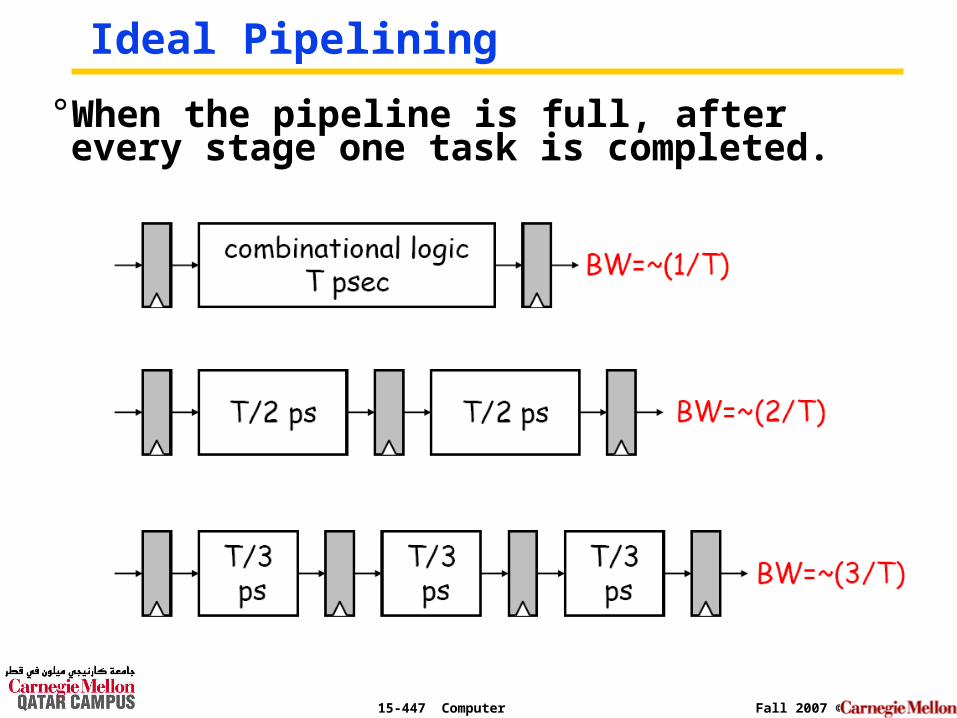
Ideal Pipelining
° When the pipeline is full, after every stage one task is completed.
15-447 Computer Architecture Fall 2007 ©
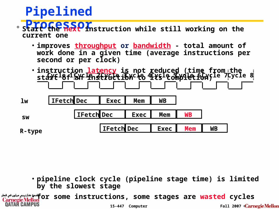
Pipelined Processor° Start the next instruction while still working on the current one
• improves throughput or bandwidth - total amount of work done in a given time (average instructions per second or per clock)
• instruction latency is not reduced (time from the start of an instruction to its completion)
• pipeline clock cycle (pipeline stage time) is limited by the slowest stage
• for some instructions, some stages are wasted cycles
Cycle 1 Cycle 2 Cycle 3 Cycle 4 Cycle 5
IFetch Dec Exec Mem WBlw
Cycle 7Cycle 6 Cycle 8
sw IFetch Dec Exec Mem WB
R-type IFetch Dec Exec Mem WB
15-447 Computer Architecture Fall 2007 ©
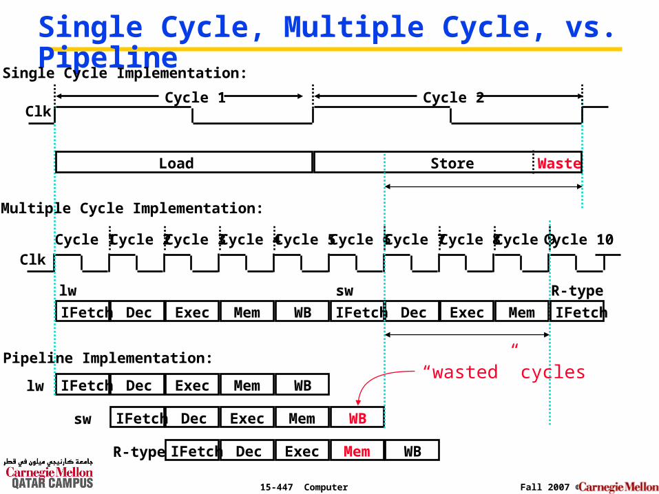
Single Cycle, Multiple Cycle, vs. Pipeline
ClkCycle 1
Multiple Cycle Implementation:
IFetch Dec Exec Mem WB
Cycle 2 Cycle 3 Cycle 4 Cycle 5 Cycle 6 Cycle 7 Cycle 8 Cycle 9Cycle 10
lw IFetch Dec Exec Mem WB
IFetch Dec Exec Mem
lw sw
Pipeline Implementation:
IFetch Dec Exec Mem WBsw
Clk
Single Cycle Implementation:
Load Store Waste
IFetch
R-type
IFetch Dec Exec Mem WBR-type
Cycle 1 Cycle 2
“wasted” cycles
15-447 Computer Architecture Fall 2007 ©
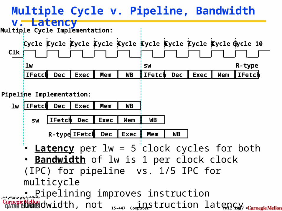
Multiple Cycle v. Pipeline, Bandwidth v. Latency
ClkCycle 1
Multiple Cycle Implementation:
IFetch Dec Exec Mem WB
Cycle 2 Cycle 3 Cycle 4 Cycle 5 Cycle 6 Cycle 7 Cycle 8 Cycle 9Cycle 10
lw IFetch Dec Exec Mem WB
IFetch Dec Exec Mem
lw sw
Pipeline Implementation:
IFetch Dec Exec Mem WBsw
IFetch
R-type
IFetch Dec Exec Mem WBR-type
• Latency per lw = 5 clock cycles for both• Bandwidth of lw is 1 per clock clock (IPC) for pipeline
vs. 1/5 IPC for multicycle• Pipelining improves instruction bandwidth, not instruction latency
15-447 Computer Architecture Fall 2007 ©
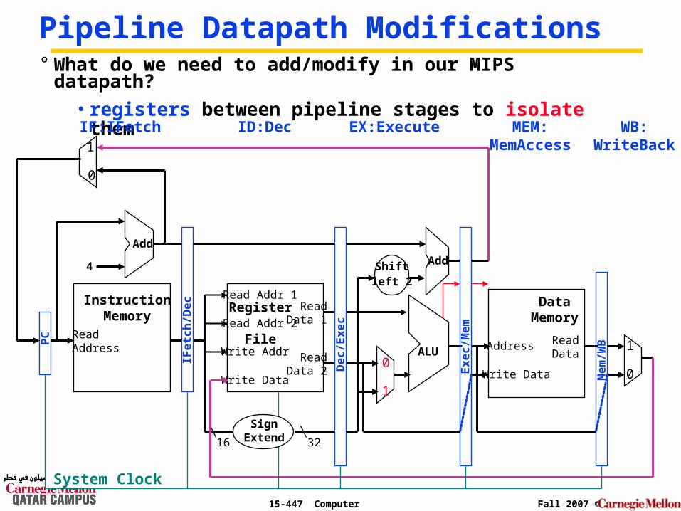
Pipeline Datapath Modifications
ReadAddress
InstructionMemory
Add
PC
4
0
1
Write Data
Read Addr 1
Read Addr 2
Write Addr
Register
File
Read Data 1
Read Data 2
16 32
ALU
1
0
Shiftleft 2
Add
DataMemory
Address
Write Data
ReadData
1
0
° What do we need to add/modify in our MIPS datapath?
• registers between pipeline stages to isolate them
IFe
tch
/De
c
De
c/E
xe
c
Ex
ec
/Me
m
Me
m/W
B
IF:IFetch ID:Dec EX:Execute MEM:MemAccess
WB:WriteBack
System Clock
SignExtend
15-447 Computer Architecture Fall 2007 ©
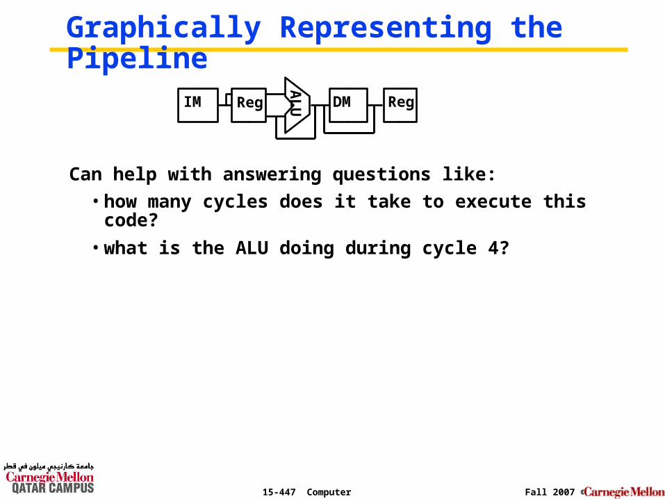
Graphically Representing the Pipeline
Can help with answering questions like:
• how many cycles does it take to execute this code?
• what is the ALU doing during cycle 4?
AL
UIM Reg DM Reg
15-447 Computer Architecture Fall 2007 ©
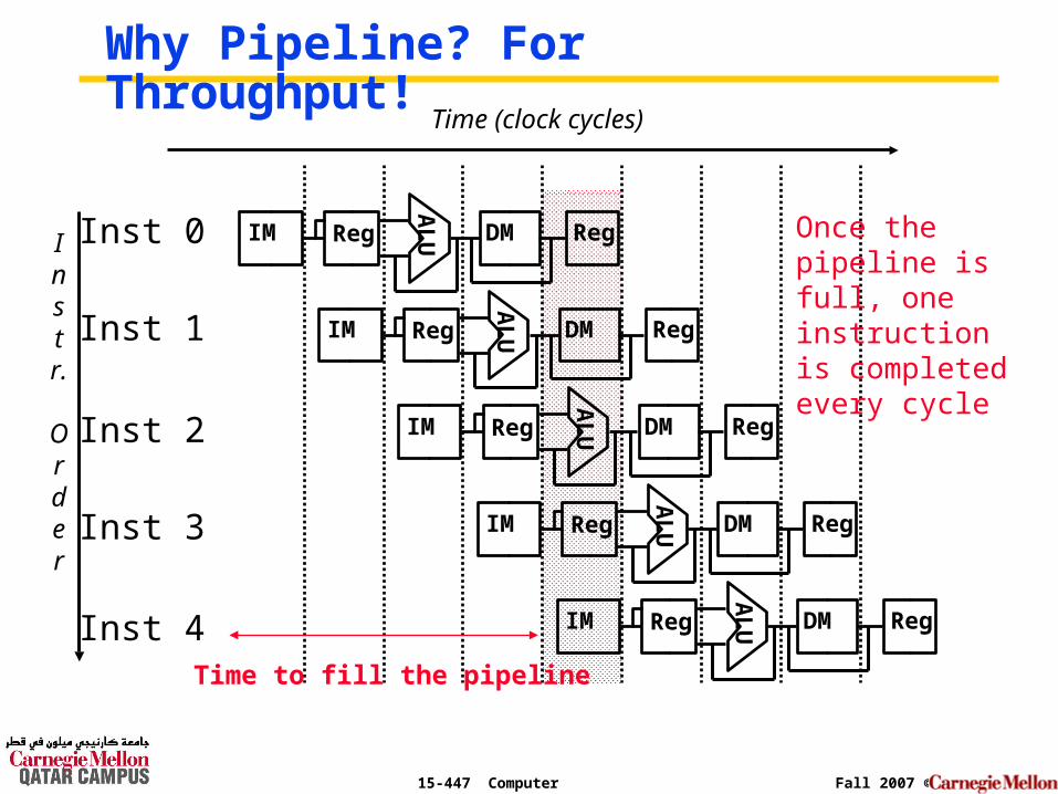
Why Pipeline? For Throughput!
Instr.
Order
Time (clock cycles)
Inst 0
Inst 1
Inst 2
Inst 4
Inst 3
AL
UIM Reg DM Reg
AL
UIM Reg DM Reg
AL
UIM Reg DM RegA
LUIM Reg DM Reg
AL
UIM Reg DM Reg
Once the pipeline is full, one instruction is completed every cycle
Time to fill the pipeline
15-447 Computer Architecture Fall 2007 ©
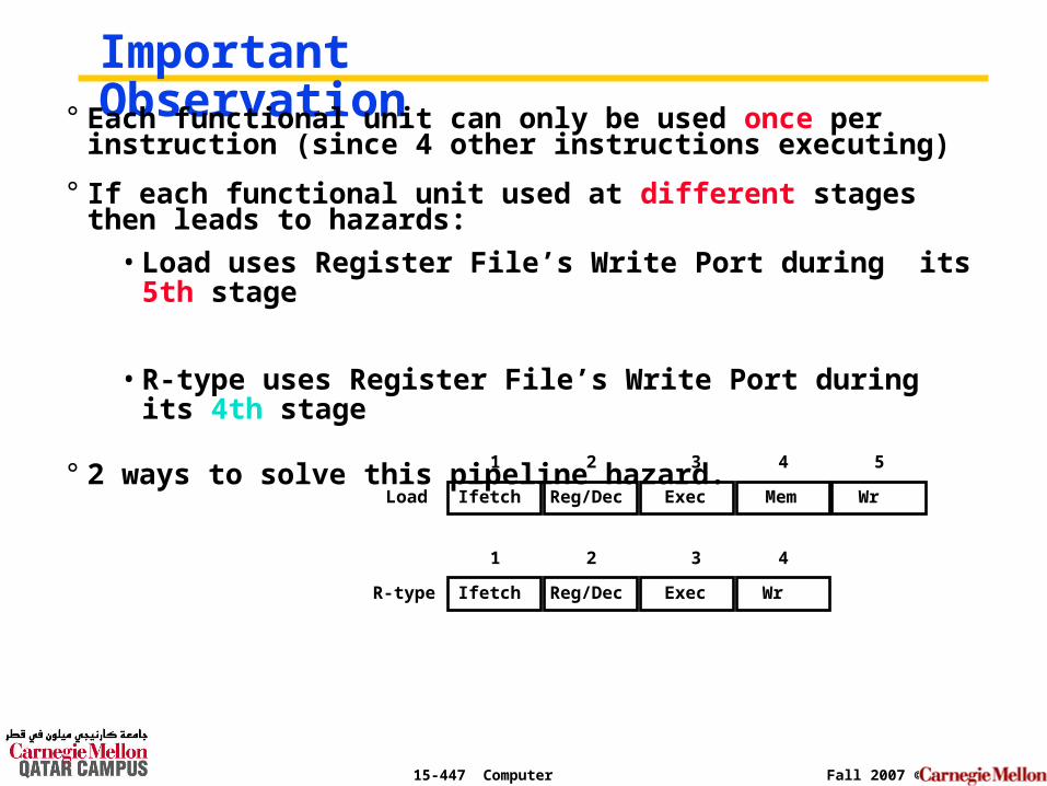
Important Observation° Each functional unit can only be used once per instruction
(since 4 other instructions executing)
° If each functional unit used at different stages then leads to hazards:
• Load uses Register File’s Write Port during its 5th stage
• R-type uses Register File’s Write Port during its 4th stage
° 2 ways to solve this pipeline hazard.
Ifetch Reg/Dec Exec Mem WrLoad
1 2 3 4 5
Ifetch Reg/Dec Exec WrR-type
1 2 3 4
15-447 Computer Architecture Fall 2007 ©
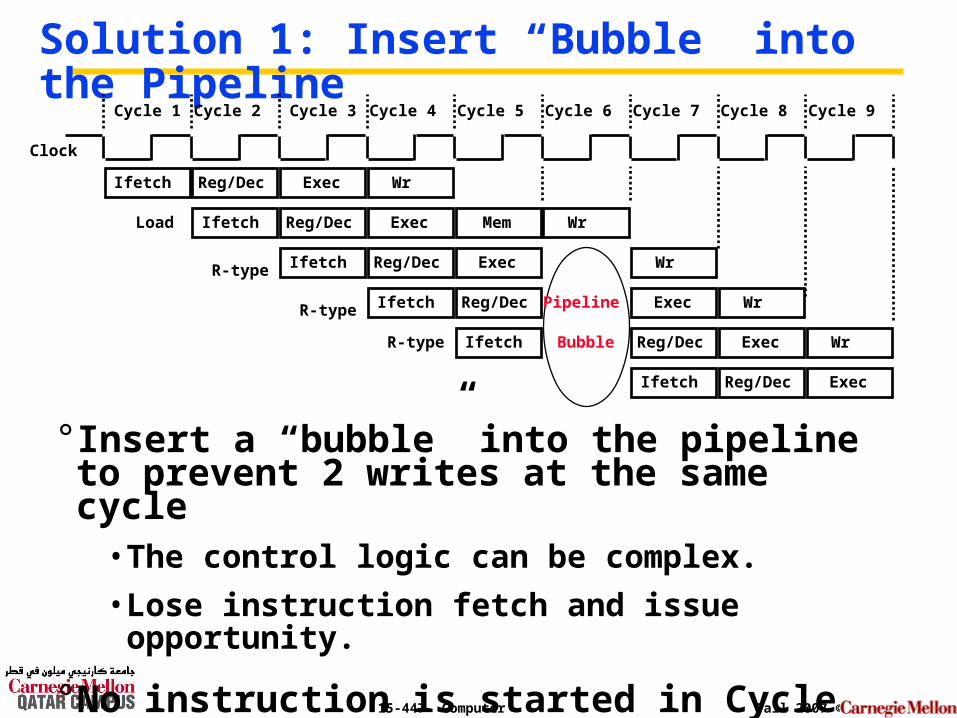
Solution 1: Insert “Bubble” into the Pipeline
° Insert a “bubble” into the pipeline to prevent 2 writes at the same cycle
• The control logic can be complex.
• Lose instruction fetch and issue opportunity.
° No instruction is started in Cycle 6!
Clock
Cycle 1 Cycle 2 Cycle 3 Cycle 4 Cycle 5 Cycle 6 Cycle 7 Cycle 8 Cycle 9
Ifetch Reg/Dec Exec WrR-type
Ifetch Reg/Dec Exec
Ifetch Reg/Dec Exec Mem WrLoad
Ifetch Reg/Dec Exec WrR-type
Ifetch Reg/Dec Exec WrR-type Pipeline
Bubble
Ifetch Reg/Dec Exec Wr
15-447 Computer Architecture Fall 2007 ©
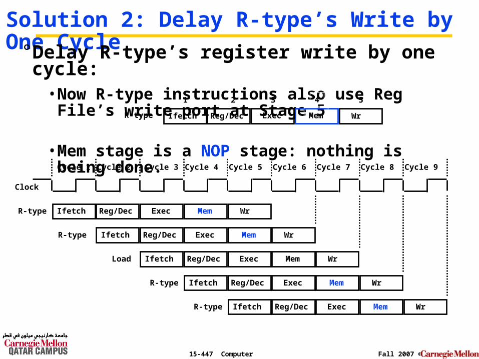
Solution 2: Delay R-type’s Write by One Cycle° Delay R-type’s register write by one cycle:
• Now R-type instructions also use Reg File’s write port at Stage 5
• Mem stage is a NOP stage: nothing is being done.
Clock
Cycle 1 Cycle 2 Cycle 3 Cycle 4 Cycle 5 Cycle 6 Cycle 7 Cycle 8 Cycle 9
Ifetch Reg/Dec Mem WrR-type
Ifetch Reg/Dec Mem WrR-type
Ifetch Reg/Dec Exec Mem WrLoad
Ifetch Reg/Dec Mem WrR-type
Ifetch Reg/Dec Mem WrR-type
Ifetch Reg/Dec Exec WrR-type Mem
Exec
Exec
Exec
Exec
1 2 3 4 5
15-447 Computer Architecture Fall 2007 ©
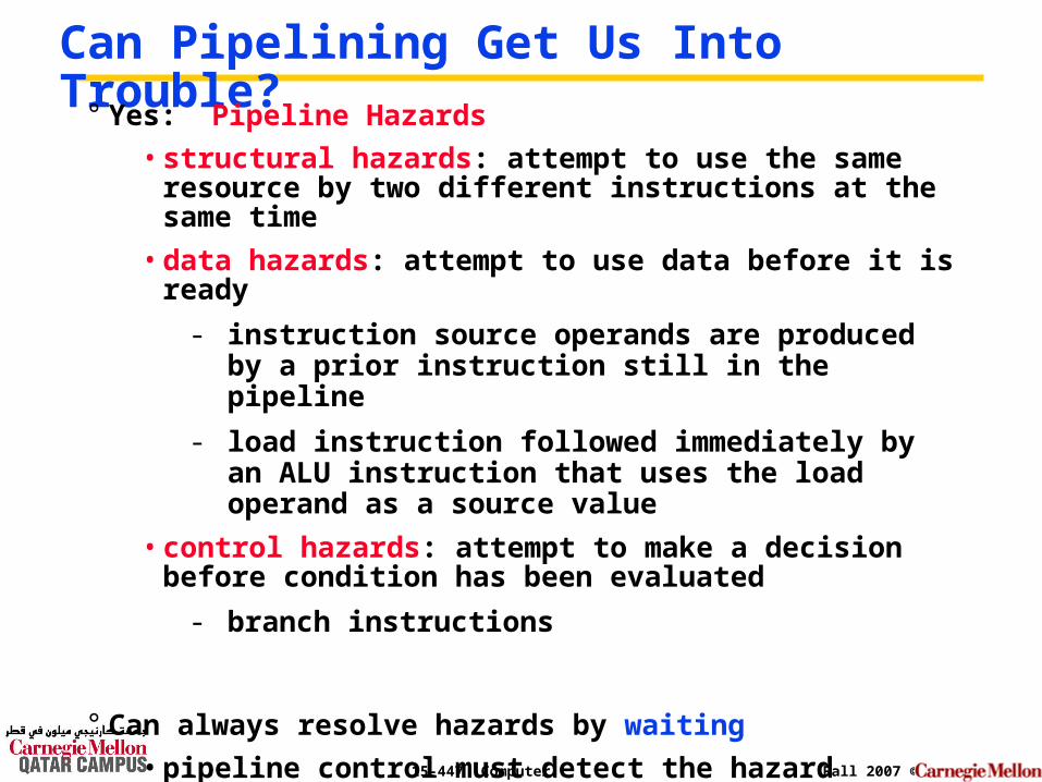
Can Pipelining Get Us Into Trouble?
° Yes: Pipeline Hazards
• structural hazards: attempt to use the same resource by two different instructions at the same time
• data hazards: attempt to use data before it is ready
- instruction source operands are produced by a prior instruction still in the pipeline
- load instruction followed immediately by an ALU instruction that uses the load operand as a source value
• control hazards: attempt to make a decision before condition has been evaluated
- branch instructions
° Can always resolve hazards by waiting
• pipeline control must detect the hazard
• take action (or delay action) to resolve hazards
15-447 Computer Architecture Fall 2007 ©
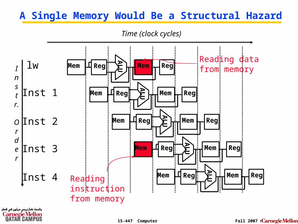
Structural Hazard°Attempt to use same hardware for two different things at the same time.
°Solution 1: Wait• Must detect hazard
• Must have mechanism to stall
°Solution 2: Throw more hardware at the problem
15-447 Computer Architecture Fall 2007 ©
Instr.
Order
Time (clock cycles)
lw
Inst 1
Inst 2
Inst 4
Inst 3
AL
UMem Reg Mem Reg
AL
UMem Reg Mem Reg
AL
UMem Reg Mem RegA
LUMem Reg Mem Reg
AL
UMem Reg Mem Reg
A Single Memory Would Be a Structural Hazard
Reading data from memory
Reading instruction from memory
15-447 Computer Architecture Fall 2007 ©
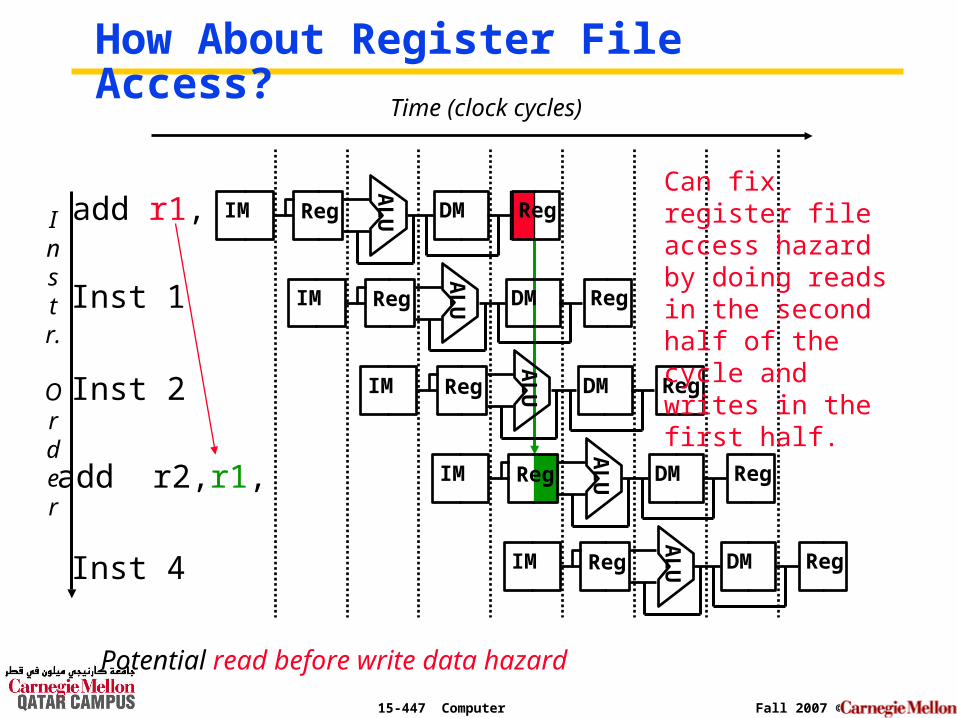
How About Register File Access?
Instr.
Order
Time (clock cycles)
Inst 1
Inst 2
Inst 4A
LUIM Reg DM Reg
AL
UIM Reg DM Reg
AL
UIM Reg DM RegA
LUIM Reg DM Reg
AL
UIM Reg DM Reg
Can fix register file access hazard by doing reads in the second half of the cycle and writes in the first half.
add r1,
add r2,r1,
Potential read before write data hazard
15-447 Computer Architecture Fall 2007 ©
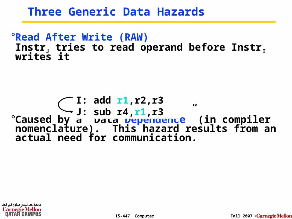
°Read After Write (RAW) InstrJ tries to read operand before InstrI writes it
°Caused by a “Data Dependence” (in compiler nomenclature). This hazard results from an actual need for communication.
Three Generic Data Hazards
I: add r1,r2,r3J: sub r4,r1,r3
15-447 Computer Architecture Fall 2007 ©
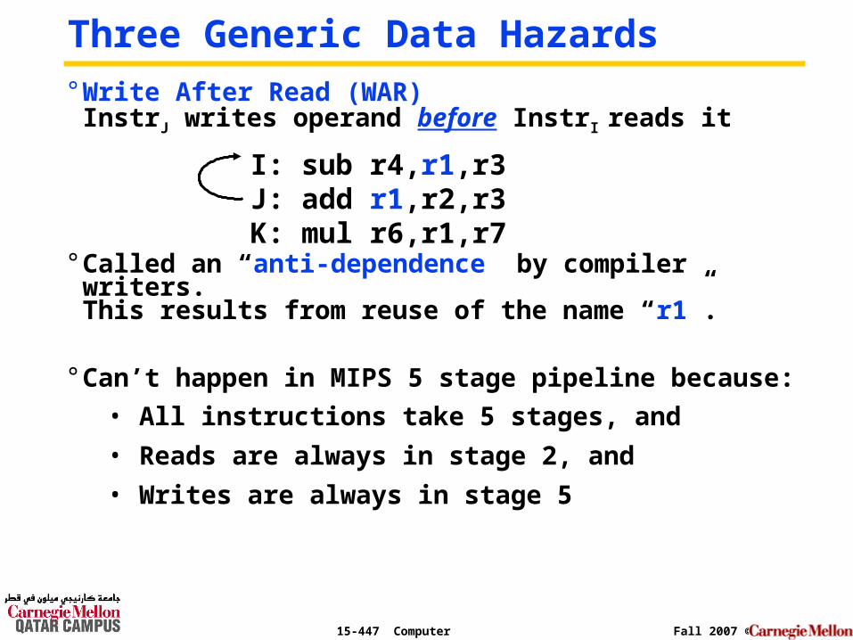
° Write After Read (WAR) InstrJ writes operand before InstrI reads it
° Called an “anti-dependence” by compiler writers.This results from reuse of the name “r1”.
° Can’t happen in MIPS 5 stage pipeline because:
• All instructions take 5 stages, and
• Reads are always in stage 2, and
• Writes are always in stage 5
I: sub r4,r1,r3 J: add r1,r2,r3K: mul r6,r1,r7
Three Generic Data Hazards
15-447 Computer Architecture Fall 2007 ©
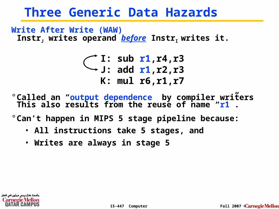
Three Generic Data HazardsWrite After Write (WAW)
InstrJ writes operand before InstrI writes it.
° Called an “output dependence” by compiler writersThis also results from the reuse of name “r1”.
° Can’t happen in MIPS 5 stage pipeline because:
• All instructions take 5 stages, and
• Writes are always in stage 5
I: sub r1,r4,r3 J: add r1,r2,r3K: mul r6,r1,r7
15-447 Computer Architecture Fall 2007 ©
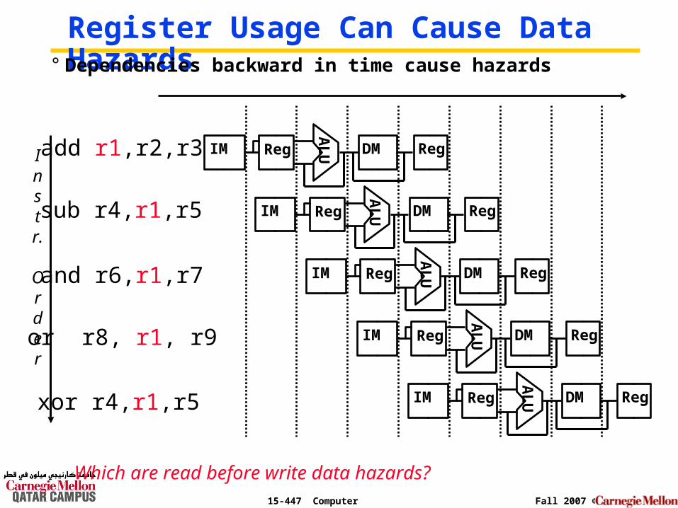
Register Usage Can Cause Data Hazards
Instr.
Order
add r1,r2,r3
sub r4,r1,r5
and r6,r1,r7
xor r4,r1,r5
or r8, r1, r9A
LUIM Reg DM Reg
AL
UIM Reg DM Reg
AL
UIM Reg DM Reg
AL
UIM Reg DM Reg
AL
UIM Reg DM Reg
° Dependencies backward in time cause hazards
Which are read before write data hazards?
15-447 Computer Architecture Fall 2007 ©
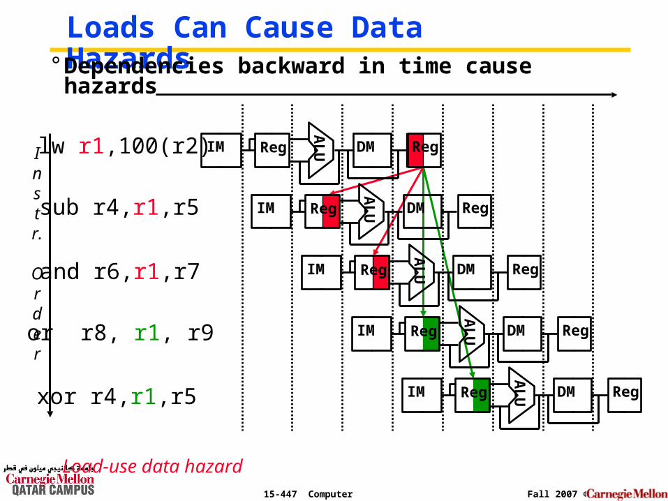
Loads Can Cause Data Hazards
Instr.
Order
lw r1,100(r2)
sub r4,r1,r5
and r6,r1,r7
xor r4,r1,r5
or r8, r1, r9A
LUIM Reg DM Reg
AL
UIM Reg DM Reg
AL
UIM Reg DM Reg
AL
UIM Reg DM Reg
AL
UIM Reg DM Reg
° Dependencies backward in time cause hazards
Load-use data hazard
15-447 Computer Architecture Fall 2007 ©
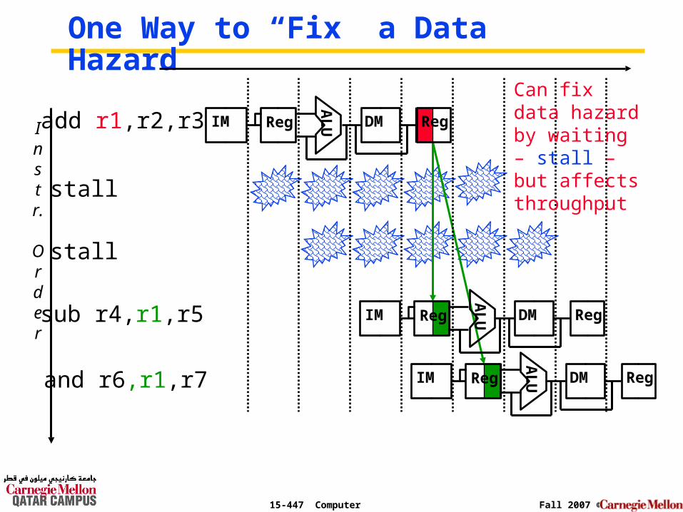
stall
stall
One Way to “Fix” a Data Hazard
Instr.
Order
add r1,r2,r3
AL
UIM Reg DM Reg
sub r4,r1,r5
and r6,r1,r7
AL
UIM Reg DM Reg
AL
UIM Reg DM Reg
Can fix data hazard by waiting – stall – but affects throughput
15-447 Computer Architecture Fall 2007 ©
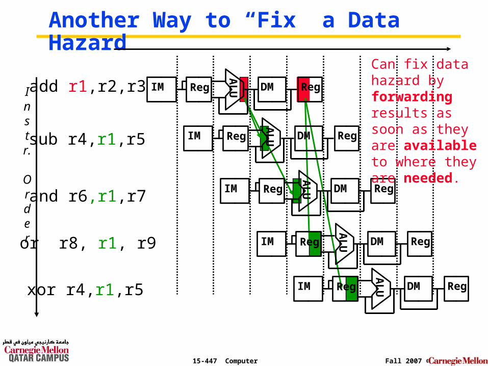
Another Way to “Fix” a Data Hazard
Instr.
Order
add r1,r2,r3
AL
UIM Reg DM Reg
sub r4,r1,r5
and r6,r1,r7A
LUIM Reg DM Reg
AL
UIM Reg DM Reg
Can fix data hazard by forwarding results as soon as they are available to where they are needed.
xor r4,r1,r5
or r8, r1, r9
AL
UIM Reg DM Reg
AL
UIM Reg DM Reg
15-447 Computer Architecture Fall 2007 ©
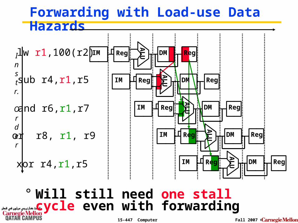
Forwarding with Load-use Data Hazards
Instr.
Order
lw r1,100(r2)
sub r4,r1,r5
and r6,r1,r7
xor r4,r1,r5
or r8, r1, r9
AL
UIM Reg DM Reg
AL
UIM Reg DM Reg
AL
UIM Reg DM Reg
AL
UIM Reg DM Reg
AL
UIM Reg DM Reg
° Will still need one stall cycle even with forwarding
15-447 Computer Architecture Fall 2007 ©
Control Hazards°Caused by delay between the fetching of instructions and decisions about changes in control flow
• Branches
• Jumps
15-447 Computer Architecture Fall 2007 ©
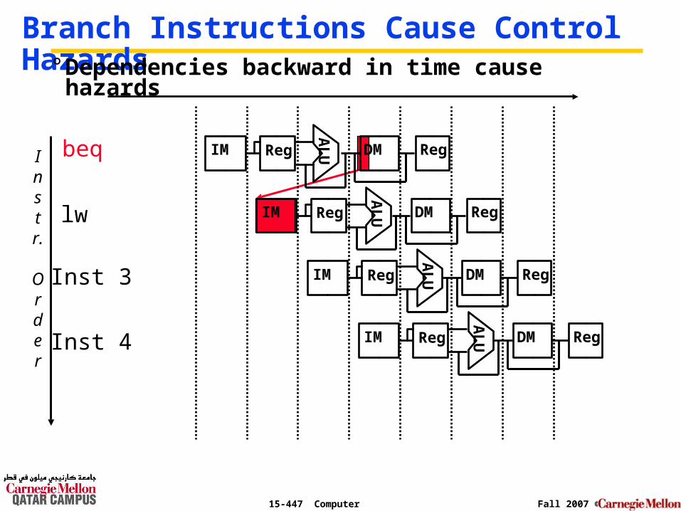
Branch Instructions Cause Control Hazards
Instr.
Order
lw
Inst 4
Inst 3
beq
AL
UIM Reg DM Reg
AL
UIM Reg DM Reg
AL
UIM Reg DM Reg
AL
UIM Reg DM Reg
° Dependencies backward in time cause hazards
15-447 Computer Architecture Fall 2007 ©
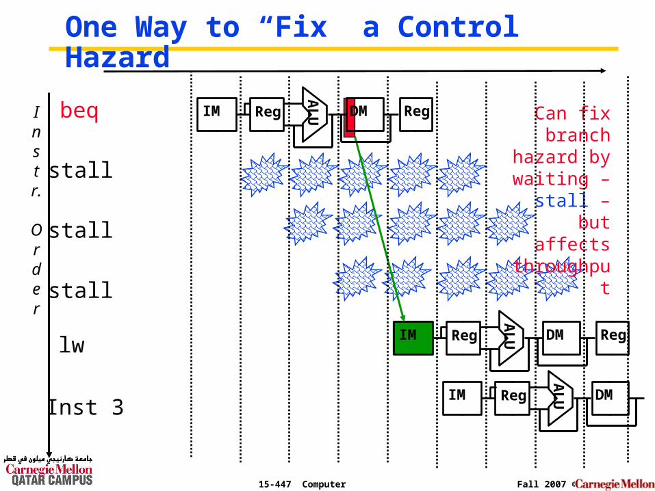
stall
stall
stall
One Way to “Fix” a Control Hazard
Instr.
Order
beq
AL
UIM Reg DM Reg
lw
AL
UIM Reg DM Reg
AL
U
Inst 3IM Reg DM
Can fix branch
hazard by waiting –
stall – but affects
throughput
15-447 Computer Architecture Fall 2007 ©
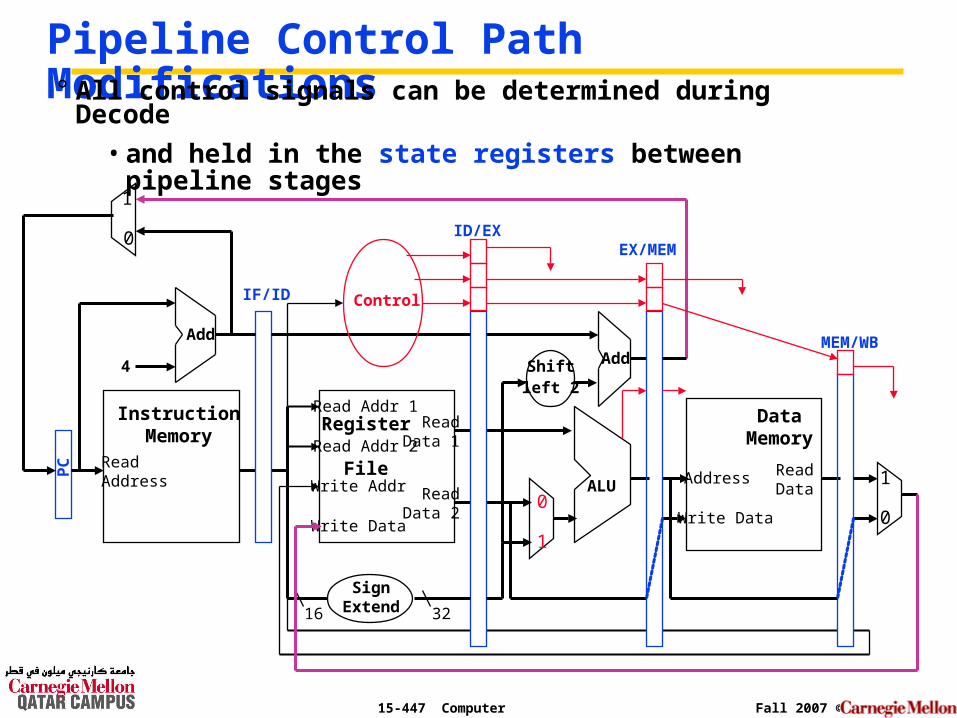
Pipeline Control Path Modifications° All control signals can be determined during Decode
• and held in the state registers between pipeline stages
ReadAddress
InstructionMemory
Add
PC
4
0
1
Write Data
Read Addr 1
Read Addr 2
Write Addr
Register
File
Read Data 1
Read Data 2
16 32
ALU
1
0
Shiftleft 2
Add
DataMemory
Address
Write Data
ReadData
1
0
IF/ID
SignExtend
ID/EXEX/MEM
MEM/WB
Control
15-447 Computer Architecture Fall 2007 ©
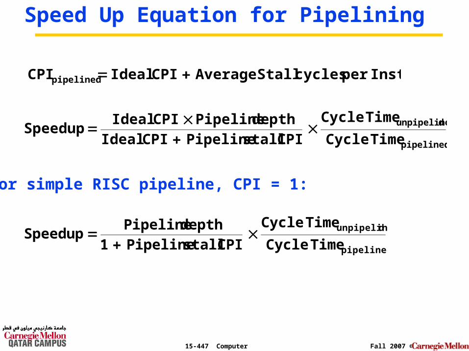
Speed Up Equation for Pipelining
pipelined
dunpipeline
TimeCycle
TimeCycle
CPI stall Pipeline CPI Idealdepth Pipeline CPI Ideal
Speedup
pipelined
dunpipeline
TimeCycle
TimeCycle
CPI stall Pipeline 1depth Pipeline
Speedup
Instper cycles Stall Average CPI Ideal CPIpipelined
For simple RISC pipeline, CPI = 1:
15-447 Computer Architecture Fall 2007 ©
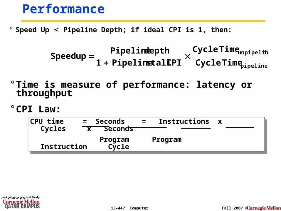
Performance
° Speed Up Pipeline Depth; if ideal CPI is 1, then:
pipelined
dunpipeline
TimeCycle
TimeCycle
CPI stall Pipeline 1depth Pipeline
Speedup
CPU time = Seconds = Instructions x Cycles x Seconds
Program Program Instruction Cycle
CPU time = Seconds = Instructions x Cycles x Seconds
Program Program Instruction Cycle
° Time is measure of performance: latency or throughput
° CPI Law:
15-447 Computer Architecture Fall 2007 ©
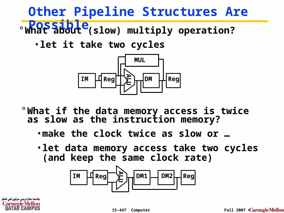
Other Pipeline Structures Are Possible° What about (slow) multiply operation?
• let it take two cycles
AL
UIM Reg DM Reg
MUL
AL
UIM Reg DM1 RegDM2
° What if the data memory access is twice as slow as the instruction memory?
• make the clock twice as slow or …
• let data memory access take two cycles (and keep the same clock rate)
15-447 Computer Architecture Fall 2007 ©
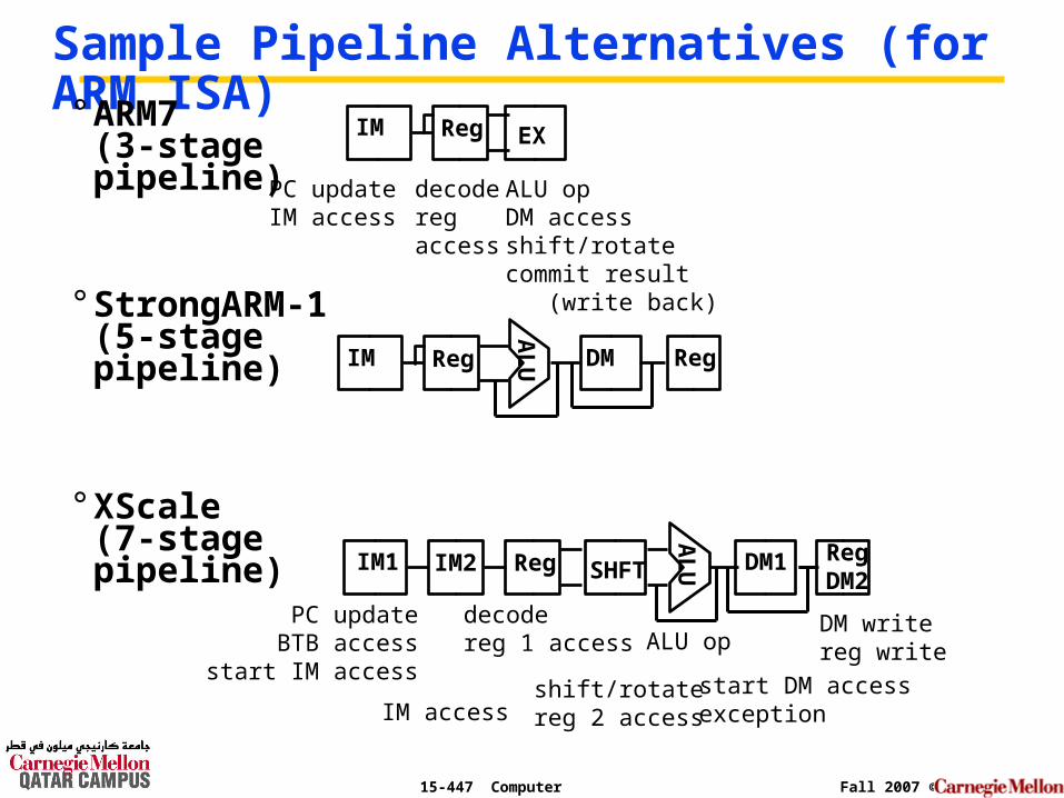
Sample Pipeline Alternatives (for ARM ISA)° ARM7
(3-stage pipeline)
° StrongARM-1(5-stage pipeline)
° XScale(7-stage pipeline)
AL
UIM1 IM2 DM1 RegDM2
IM Reg EX
PC updateIM access
decoderegaccess
ALU opDM accessshift/rotatecommit result (write back)
AL
UIM Reg DM Reg
Reg SHFT
PC updateBTB access
start IM access
IM access
decodereg 1 access
shift/rotatereg 2 access
ALU op
start DM accessexception
DM writereg write
15-447 Computer Architecture Fall 2007 ©
Summary
° All modern day processors use pipelining
° Pipelining doesn’t help latency of single task, it helps throughput of entire workload
• Multiple tasks operating simultaneously using different resources
° Potential speedup = Number of pipe stages
° Pipeline rate limited by slowest pipeline stage
• Unbalanced lengths of pipe stages reduces speedup
• Time to “fill” pipeline and time to “drain” it reduces speedup
° Must detect and resolve hazards
• Stalling negatively affects throughput