16
REDUCING TOTAL COST OF OWNERSHIP WITH RF ROUTER TCO COMPARISON OF CRAN AND RF ROUTER Dali Wireless | Whitepaper | February 2015 DALI WIRELESS © FEBRUARY 2015 | Whitepaper

REDUCING TOTAL COST OF OWNERSHIP WITH RF ROUTER TCO COMPARISON OF C-‐RAN AND RF ROUTER
Dali Wireless | Whitepaper | February 2015
DALI WIRELESS © FEBRUARY 2015 | Whitepaper

2

3
Executive Summary
A comparison of total cost of ownership (TCO) for a C-RAN and a RF Router solution has been
calculated on the basis of an existing typical airport campus, applying identical business
requirements for both solutions.
• Compared to a C-RAN solution under same conditions, the RF Router solution offers
typically 30...40% better TCO performance over a 3-year period. Up to 60% better
TCO can be achieved for multi-operator use cases.
• Evaluating just initial CAPEX provides an incomplete picture – it’s an OPEX game
• Hidden costs of operational complexity are a major contributor to TCO
• C-RAN is currently mentioned only in 4G context. Nothing prevents from deploying
this architecture also in 3G or 2G, but no known commercial products are available to
date.
• C-RAN requires all base stations to be collocated in a single location due to mechanical
coupling of baseband units. A RF Router based solution can be distributed over a wide
area with up to 40 km distance between base station locations.
In addition to the cost benefit, scalability and elasticity of the RF Router solution unlocks new
business opportunities for operators by enabling a virtualized radio access network (v-RAN).
4
The Traffic Tsunami -‐ Getting Ready for 1000x Traffic
Mobile data traffic volumes have been growing steadily over the last years, almost doubling
from one year to the next. A main driver for the increase in data traffic are mobile streaming
services, mainly video but also the upload of user generated content
Analysts have predicted a „traffic tsunami“ – a 1000x increase in traffic volumes—within the
next decade. Looking at the current annual growth rates, it seems this estimation may not be
too far off.
Former „hot spots“ in the network have
enlarged and have become „hot zones“ which
carry significant volumes of traffic per day.
Many of these hot zones are located within
buildings and larger building complexes and
some 80..85% of total network traffic volume
now originates from indoor environments. The
traditional outdoor, high-mobility users in the
macro-cell network have become the minority
and the trend continues.
Hot zones and dense mobile network call for a
different approach than the traditional point-relief offered by a single micro- , metro-, pico- or
small cell positioned at an specific identified network hotspot.
As network traffic patterns become less predictable, areas of heavy traffic demand pop up
randomly at different locations as users move through the network. This traffic characteristic
calls for a flexible and adaptive distribution of network capacity, where and when needed by
the users. Operators need not just a single point-relief cure, but a scalable high-density RAN
solution to effectively cope with the looming threat of the „traffic tsunami“.
Figure 1: Analysts predict a “traffic tsunami” – a 1000x increase in data volumes within the next decade

5
Avoiding the Capacity Crunch
In the early days of mobile networks, network coverage was an operator’s key asset and the
basis for the value proposition. Meanwhile, networks in most countries have developed to a
degree that ubiquituous signal coverage can be taken for granted in the populated areas.
The key criterion now is which data rates and
network capacity can be be provided to the users
at any time. This directly translates to user
experience.
Capacity demand is growing exponen-tially, while
capacity supply is limited with the technology
deployed, the radio resources available to the
operator and the amount of spectrum allocated. If
it has not occurred yet, the „capacity crunch“ as
the limiting factor for the operator’s ability to
provide sufficient capacity where and when
needed is approaching rapidly.
Operators need to find ways of avoiding the
capacity crunch by employing means and techniques utilizing the available radio and spectrum
resources in the most efficient way.
Ways to Increase Radio Capacity
The laws of physics set a hard limit for how much information capacity can be provided within
a certain spectrum bandwidth (Shannon’s theorem). Within this limit there are several ways to
increase radio capacity:
• New technology with more efficient modulation and coding schemes: This has
been applied several times during the last 20 years, moving from 10 kbps speeds in
GSM to 100’s kbps in EDGE and early 3G. Advanced 3G technologies („3.5G“, HSPA)
have brought speeds to the order of 10 Mbps, now approaching 50 Mbps with
4G/LTE. This trend will certainly continue over the next few years with 5G, 6G and
further, but traffic demand rises much faster than new technologies can be
developed and deployed. Processor power - governed by Moore's law but also
battery capacity are the limiting factors besides the proximity of the Shannon limit.
• More spectrum: Increasing the amount of available basic resources is a simple
Figure 2: “Capacity Crunch”: The gap between traffic demand and supply is widening as data traffic continues to grow exponentially

6
method to increase capacity. However, this is just „more-of-the-same“, providing no
technical advance. This method can be applied as long as sufficient spectrum
resources can be made available. Spectrum is definitively a finite and scarce
resource. Clearing of new frequency bands for mobile communication is a process of
several years and traffic demand grows much faster than new spectrum can be made
available and be allocated.
• Additional cells: Reducing the
coverage areas of cells and re-
using the radio resources as often
as possible is an efficient way of
increasing capacity. However,
there are limits: As cell sizes
become smaller, interfering signals
from neighbouring cells become
stronger. From a certain point
onwards, capacity losses due to
interference are higher than the
potential capacity gain by reducing
cell size and the overall network
capacity decreases.
• Increase efficiency, reduce waste: Another efficient method to increase capacity is
to overcome the typical limiting factors of interference and static capacity allocation
by avoiding interference through selective simulcasting and following the network
traffic demand patterns by a dynamic allocation of RF resources exactly where and
when needed thus increasing the yield of the resources used.
This is the method applied by the Dali RF Router system. For more details, please see
Dali white paper „Introducing the RF Router System“ on
www.daliwireless.com/whitepapers
Designing for Capacity
In network hot-spots or in known temporary hot-zones such as a sports stadium the traditional
approach is to allocate as many radio resources as possible to cater for the short duration of a
large traffic peak. This approach works fine for temporary and isolated traffic peaks and is not
suitable as a permanent solution for multiple areas or zones in a network.
A different method is to design the network for total expected capacity including fluctuations
over time in a particular target area. This area can be one or multiple buildings, a complex of
Figure 3: capacity degradation due to interference when a certain density of nodes is surpassed

7
buildings or an entire campus. Ideally, the traffic is absorbed as close as possible to the source.
This avoids traffic spill-over into adjacent areas and systematic over-provisioning of network
capacity.
New rules apply for 3G/ 4G data traffic: The traditional „more-is-better“ approach known from
1st and 2nd generation networks is no longer helpful. Interference from neighbouring cells
becomes the limiting factor in dense radio networks. Therefore, on a system level, many low-
power antenna points will provide a better throughput than few high-power transmitters with
same aggregated transmit power.
New patterns also emerge for user behaviour. Users have become more „nomadic“, consuming
large amounts of traffic while being
stationary, then moving on to another
location where again they settle down to
consume another large amount of traffic.
The large majority of total traffic volume in
networks today –well over 80%-- originates
and terminates inside buildings. Recently,
there is a shift towards more mobile usage as
powerful smart devices allow for
consumption of content on the go, e.g. in
public transport facilities.
The nomadic mobility pattern with high traffic
rates and the shift towards indoor usage emphasizes the need for a capacity-driven network
design, anticipating this user behaviour with a flexible and elastic capacity provisioning instead
of the traditional static allocation of capacity to antenna points.
Traditional macrocell approaches are not an appropriate solution to provide reliable Indoor
capacity.
Efficiency Gains by Resource Pooling
Resource pooling provides significant efficiency gains by enabling better utilization of
resources that can be shared between multiple entities.
The concept of Centralized-RAN („C-RAN“) proposes to share the baseband signal processing
resources between several cells. A pool of shared signal processing elements feed the cell’s RF
modules. While the task of signal processing is shared, the relation of cell's coverage area and
RF receiver/amplifier is still restricted to 1:1 .
The novel method of RF Routing goes one step further by dissolving this strict 1:1 relation
Figure 4: Heavy users with typical monthly data consumption of 2.. 5 GB dominate the usage

8
between radio cell and antenna location, making the cell capacity routable wherever and
whenever needed. In combination with the C-RAN functionality this enables a true virtualized
RAN (v-RAN).
Measuring the Capacity Efficiency
The notion of „capacity“ by itself is abstract. Capacity describes the capability of providing a
useful service, regardless of whether this is being used or not. E.g. a large elevator in a building
may have a nominal capacity of 35 persons, it becomes meaningful only when the capacity is
being utilized.
Similarly, data rates (in Mbit per second) is also often misleadingly called „capacity“. Data
speed integrated over time equals transported capacity.
In this paper, the term „capacity“ is understood as the utilized portion of the nominal capacity
and is stated in Mega- or Gigabytes measured over a certain time unit, e.g. one hour.
Economies of Scale Capacity comes cheaper in large quantities. In a simple model, the supported maximum data
rate of a base station’s radio cell using a
certain technology can be translated to a
typical capacity (=data volume) that can be
handled by this cell in a certain time period.
Plotting the capacity of a base station against
relative CAPEX cost it appears –not
surprisingly—that the cost function is flatter
with larger configurations than with smaller.
While small cells or base stations in small configurations (pico-cell) may provide same user
data rates as large cells, the limited processing power
will cause the total processed capacity (=data volume)
within a given time period to be lower as compared to a
full-sized base station. Putting the handled capacity of
a pico-cell into relation with its CAPEX one will find
that pico-cells, despite of their low initial cost, have a
low capacity/ price performance.

9
Efficiency Metric: „MegaByte per Dollar TCO“
For a mobile operator in a competitive business environment, keeping the production cost low
is equally important as increasing the top line revenues. The production cost of the service is
driven to a very large extent –typically 70% to 75%-- by the cost of the radio network.
Therefore evaluating only the initial CAPEX of the network is not sufficient. Rather, the total
cost of ownership (TCO) of the network needs to be evaluated, including the initial purchasing
and one-time cost of deployment as well as
all ongoing operational costs for
maintenance, servicing, repairs,
modernization and configuration changes,
i.e. the network growth path.
The overall metric for capacity efficiency is
„how much bang for the buck?“ or – in more
business-like terms-- „How many Megabytes
do I get per Dollar TCO spent?“
The graphic shows the TCO evaluated over a
3-years period for various 2G, 3G and 4G
base station capacity configurations. It shows that LTE configurations provide the best
capacity efficiency, followed by a cluster of 3G or HSPA configurations, while GSM/EDGE
configuration have a rather low performance.
Figure 6: TCO evaluated over a 3-‐years period for various 2G, 3G and 4G base station capacity configurations
10
Case Study: Mid-‐Sized Airport Campus
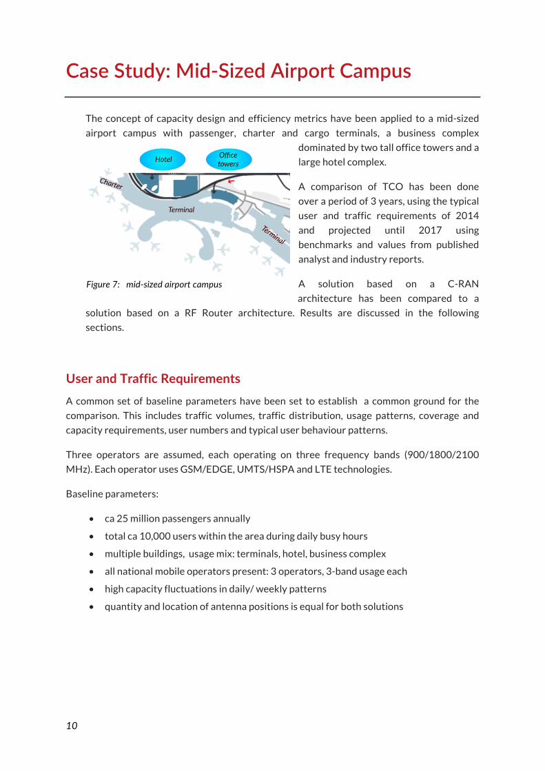
The concept of capacity design and efficiency metrics have been applied to a mid-sized
airport campus with passenger, charter and cargo terminals, a business complex
dominated by two tall office towers and a
large hotel complex.
A comparison of TCO has been done
over a period of 3 years, using the typical
user and traffic requirements of 2014
and projected until 2017 using
benchmarks and values from published
analyst and industry reports.
A solution based on a C-RAN
architecture has been compared to a
solution based on a RF Router architecture. Results are discussed in the following
sections.
User and Traffic Requirements A common set of baseline parameters have been set to establish a common ground for the
comparison. This includes traffic volumes, traffic distribution, usage patterns, coverage and
capacity requirements, user numbers and typical user behaviour patterns.
Three operators are assumed, each operating on three frequency bands (900/1800/2100
MHz). Each operator uses GSM/EDGE, UMTS/HSPA and LTE technologies.
Baseline parameters:
• ca 25 million passengers annually
• total ca 10,000 users within the area during daily busy hours
• multiple buildings, usage mix: terminals, hotel, business complex
• all national mobile operators present: 3 operators, 3-band usage each
• high capacity fluctuations in daily/ weekly patterns
• quantity and location of antenna positions is equal for both solutions
Figure 7: mid-‐sized airport campus

11
Solution Option : C-‐RAN
In current discussions and business literature, C-RAN is always mentioned in context with
4G/LTE technology. To date, there is no commercial product known implementing a C-RAN
solution. For the commercial modelling we have assumed that a eNodeB implementing C-RAN
capabilities would be 15% cheaper than a standard eNodeB, reflecting the efficiency gains
claimed by the C-RAN concept.
Furthermore, we see no obstacle in applying the C-RAN concept also to 3G or even to 2G,
although the savings benefit would be less than with 4G. There is no commercial product
available providing C-RAN for 3G, however, we have assumed that the same level of benefits
would apply for a 2G/ 3G- C-RAN configuration and have also applied a 15% discount on the
cost of C-RAN equiment compared to standard 2G-/ 3G equipment.
The architecture of the „any-G“ C-RAN solution has been modelled as shown below:
Figure 8: assumed C-‐RAN architecture for modelling

12
Solution Option : RF Router
The RF Router platform is technology-, band- and vendor-agnostic, accepting signals from any
technology (2G, 3G, 4G, incl. MIMO) for routing to the antenna locations. The RF Router
platfom can process either a digital baseband signal e.g. in CPRI-format or similar, directly
from the base station or an RF signal from the base station’s antenna connector. The latter
option is technically less efficient, but generally applicable and available without any further
interfacing components required.
For simplicity, we have modelled the RF Router platform with RF feeds, similar to an interface
with a traditional DAS systems, but with a finer granularity of capacity, providing routeability
of the individual signal feeds.
A typical architecture of the RF Router platform is shown below. For the modelling we have
assumed standard base stations („classical“) interfacing with th RF Router system:
Figure 9: RF Router architecture with different interfacing options

13
Results
Cost-‐vs-‐Capacity function
The applied calculation method considers an Operator’s total cost of ownership (TCO),
including initial deployment costs, ongoing operational costs including site rental,
backhaul, power consumption, air conditioning, vendor’s hardware/ software fees,
maintenance, spares and repairs. Over an assumed 3-years period of usage the
cumulated OPEX clearly exceeds the initial CAPEX and for a usage period of typically 5
years even more so.
In a traffic-growth scenario, incremental costs for system expansion become relevant.
Here, the results of the sensitivity analysis show that for a C-RAN architecture costs go
almost linear with the expanding
capacity. This is because the radios do
not scale well with growth and costs
for additional RF modules outweigh the
cost benefits achieved by baseband
pooling. Similarly, adding another RF
frequency band may require a full
retrofit or replacement of the RF
modules deployed in the network.
Adding another operator to the C-RAN
system – if at all feasible – will require
adding of another full set of base
stations and RF modules, since there is
no known C-RAN product on the
market that natively supports multi-
operator environments.
In contrast, the RF Router solution shows only a sub-linear increase of costs with
increasing capacity, due to the economies of scale achievable with the capacity routing
mechanisms.
When inserting additional frequency bands or additional operators to the scenario, the
cost function shows a step increase, but to a far less degree of significance. This is due to
the fact, that the radio distribution network, which represents the majority of the
network costs, is unaffected by any changes performed on the base station system
beyond the RF router function. The RF Router redistributes the available capacity blocks
differently among the connected radio units.
Figure 10: Cost-‐vs-‐Capacity function for C-‐RAN and RF Router solutions

14
TCO Performance
An evaluation of TCO (total cost of ownership) over an assumed usage period of 3 years
shows that the RF Router solution performs 35...60% better in TCO than C-RAN,
depending on the usage scenario.
In the base case with a single operator, the C-RAN solution is even slightly cheaper in
CAPEX, however, the OPEX over the
usage period turn the case in favour
of the RF Router. The higher OPEX is
caused by higher system complexity
and more active components
required to achieve the same
coverage and capacity performance.
A sensitivity analysis on the cost
components show that the typical
range is 30...40% improvement in
TCO performance for an RF Router
solution.
In the case of a multi-operator
environment, the advantage in the cost structure of the RF router becomes strikingly
evident. For the multi-operator C-RAN solution – if technically feasible at all—the lack of
scalability and elasticity of the solution drives OPEX high, resulting in a approx. 60%
TCO advantage for the RF Router.
A C-RAN solution is more expensive in TCO, because...
• less granularity in capacity allocation
• more active equipment needed (= CAPEX, OPEX)
• does not scale well with additional bands or traffic growth
• no economies of scale in multi-operator environments
• RF modules are not scalable or shareable
Figure 11: Comparison of TCO (3 yrs) for C-‐RAN and RF Router solution in single-‐ operator and multi-‐operator scenario

15
Conclusions
A comparison of an existing RF Router solution with the conceptual solution of C-RAN is not
straight-forward. The C-RAN concept is mentioned in the context of LTE networks only. To
date there is no known commercial product on the market implementing a C-RAN solution.
Furthermore, it is unclear whether C-RAN for 3G or 2G will come to the market at all.
The RF Router solution as an intelligent distribution system is completely agnostic to
technology (2G, 3G, 4G or beyond), independent of any base station vendor or type and allows
to implement multi-operator use cases, even with base stations of different vendors used by
the participating operators. All this is not easily imaginable with a C-RAN system.
Both, the C-RAN and RF Router solution are geared towards larger installations requiring high
capacity. While the C-RAN concept provides a degree of efficiency by pooling the baseband
processing resources, the RF Router solution goes one large step further by also in essence
pooling the RF modules and making the individual capacity blocks routable wherever and
whenever needed.
The RF Routing capability is the break-through step, enabling a full virtualized radio access
network (v-RAN). This opens up a new dimension of flexibility for operators to offer elastic
telecom services to enterprises and corporate customers, similar to cloud-based services in
the IT domain.
Summary
• Compared to a C-RAN solution under same operational conditions, the RF Router solution
offers typically 30...40% better TCO performance over a 3-year period. Up to 60% better
TCO can be achieved for multi-operator use cases.
• Evaluating just initial CAPEX results in an incomplete picture – it’s an OPEX game
• Hidden cost of operational complexity is a major contributor to TCO
• C-RAN is currently mentioned always in the 4G context. C-RAN architecture can also be
applied to 3G or 2G, but no commercial products are known to date.
• C-RAN requires all base stations to be collocated due to mechanical coupling of baseband
units. RF Router can be distributed over wide area with up to 40 km distance between base
station locations.
In addition to the cost benefit, scalability and elasticity of the RF Router solution unlocks new
business opportunities for operators by enabling a virtualized radio access network (v-RAN).

16
About Dali Wireless
Dali Wireless is a global provider of the award-winning all-digital RF ROUTER® platform,
purpose-built to address today’s exponential growth in mobile data traffic. With its innovative
end-to-end digital RF signal processing and software configurability, wireless coverage and
capacity can be dynamically allocated to where and when needed.
Dali RF ROUTER® delivers the high capacity of a macro-cell, the flexible coverage of DAS and
the small footprint of a pico-cell without the traditional interference challenges. Dali supports
global frequency bands and is technology- and vendor-agnostic, making it a future-proof
platform that is suitable for many situations that require dynamic capacity allocation,
intelligent coverage or RAN virtualization.
www.daliwireless.com


